EP1237276A2 - Television tuner - Google Patents
Television tuner Download PDFInfo
- Publication number
- EP1237276A2 EP1237276A2 EP02250242A EP02250242A EP1237276A2 EP 1237276 A2 EP1237276 A2 EP 1237276A2 EP 02250242 A EP02250242 A EP 02250242A EP 02250242 A EP02250242 A EP 02250242A EP 1237276 A2 EP1237276 A2 EP 1237276A2
- Authority
- EP
- European Patent Office
- Prior art keywords
- pass
- inductance element
- frequency band
- low
- frequency
- Prior art date
- Legal status (The legal status is an assumption and is not a legal conclusion. Google has not performed a legal analysis and makes no representation as to the accuracy of the status listed.)
- Withdrawn
Links
Images
Classifications
-
- H—ELECTRICITY
- H03—ELECTRONIC CIRCUITRY
- H03J—TUNING RESONANT CIRCUITS; SELECTING RESONANT CIRCUITS
- H03J5/00—Discontinuous tuning; Selecting predetermined frequencies; Selecting frequency bands with or without continuous tuning in one or more of the bands, e.g. push-button tuning, turret tuner
- H03J5/24—Discontinuous tuning; Selecting predetermined frequencies; Selecting frequency bands with or without continuous tuning in one or more of the bands, e.g. push-button tuning, turret tuner with a number of separate pretuned tuning circuits or separate tuning elements selectively brought into circuit, e.g. for waveband selection or for television channel selection
- H03J5/242—Discontinuous tuning; Selecting predetermined frequencies; Selecting frequency bands with or without continuous tuning in one or more of the bands, e.g. push-button tuning, turret tuner with a number of separate pretuned tuning circuits or separate tuning elements selectively brought into circuit, e.g. for waveband selection or for television channel selection used exclusively for band selection
- H03J5/244—Discontinuous tuning; Selecting predetermined frequencies; Selecting frequency bands with or without continuous tuning in one or more of the bands, e.g. push-button tuning, turret tuner with a number of separate pretuned tuning circuits or separate tuning elements selectively brought into circuit, e.g. for waveband selection or for television channel selection used exclusively for band selection using electronic means
-
- H—ELECTRICITY
- H04—ELECTRIC COMMUNICATION TECHNIQUE
- H04N—PICTORIAL COMMUNICATION, e.g. TELEVISION
- H04N21/00—Selective content distribution, e.g. interactive television or video on demand [VOD]
- H04N21/40—Client devices specifically adapted for the reception of or interaction with content, e.g. set-top-box [STB]; Operations thereof
- H04N21/41—Structure of client; Structure of client peripherals
- H04N21/426—Internal components of the client ; Characteristics thereof
- H04N21/42607—Internal components of the client ; Characteristics thereof for processing the incoming bitstream
- H04N21/4263—Internal components of the client ; Characteristics thereof for processing the incoming bitstream involving specific tuning arrangements, e.g. two tuners
-
- H—ELECTRICITY
- H04—ELECTRIC COMMUNICATION TECHNIQUE
- H04N—PICTORIAL COMMUNICATION, e.g. TELEVISION
- H04N5/00—Details of television systems
- H04N5/44—Receiver circuitry for the reception of television signals according to analogue transmission standards
- H04N5/50—Tuning indicators; Automatic tuning control
Definitions
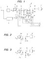
- the present invention relates to a television tuner that receives a television signal from the VHF band to the UHF band.
- An input tuned circuit 34 of the first tuner 32 is provided with a band switching type tuned circuit and switched so as tune to a television signal in a low-pass frequency band from over 40 MHz to 130 or 150 MHz (for example, 140 MHz) or a television signal in a high-pass frequency band from 130 MHz or 150 MHz to 410 MHz or 440 MHz.
- the television signal selected by this input tuned circuit 34 is input to an input terminal G1 of an amplifying element 35a (field-effect transistor) of a high - frequency amplifier 35.
- An input tuned circuit 4 of the first tuner 2 has a band switching type tuned circuit and is switched so as tune to a television signal in a low-pass frequency band from over 40 MHz to 130 or 150 MHz (for example, 140 MHz) or a television signal in a high-pass frequency band from 130 MHz or 150 MHz to 410 MHz or 440 MHz.
- the television signal selected by this input tuned circuit 4 is input to an input terminal G1 of an amplifying element 5a (field-effect transistor) of a high-frequency amplifier 5.
- a first high-pass tuning inductance element 8a at the primary side of the double-tuned circuit 8 is connected to the output terminal D of the amplifying element 5a via a first coupling capacitive element 9.
- a first inductance element is connected to an output terminal of an amplifying element and a second inductance element is connected to the ground.
- a high-pass tuning inductance element of which one end is connected to the output terminal of the amplifying element via a first coupling capacitive element and a low-pass tuning inductance element connected in series to the high-pass tuning inductance element are provided in a double-tuned circuit via the first coupling capacitive element.
- the connection point between the first inductance element and the second inductance element and the connection point between the high-pass tuning inductance element and the low-pass tuning inductance element are connected using a second coupling capacitive element.
- the resonant frequencies of the series circuit having the first inductance element and the second coupling capacitive element and the parallel circuit having the first coupling capacitive element are set within a bandwidth in a high-pass frequency band, a trap circuit that attenuates the high-pass frequency band is constructed.
- the selectivity when a television signal in a low-pass frequency band, in the vicinity of the upper limit in particular, is improved and jamming ca be made unlikely to be caused.
Landscapes
- Input Circuits Of Receivers And Coupling Of Receivers And Audio Equipment (AREA)
- Amplifiers (AREA)
Abstract
Description
Claims (5)
- A television tuner, comprising:wherein an output capacity component of an amplifying element that constructs the high-frequency amplifier and an inductance element that constructs a parallel-resonant circuit are provided between the high-frequency amplifier and the double-tuned circuit, wherein an inductance value of the inductance element is switched being linked with band switching of the double-tuned circuit, and wherein the parallel-resonant circuit is made to resonate in the vicinity of a minimum frequency in the high-pass frequency band or in the vicinity of a minimum frequency in the low-pass frequency band.a high-frequency amplifier that amplifies a television signal in all bandwidths of the VHF band and a television signal in a bandwidth at a low-pass side of the UHF band and a band switching type double-tuned circuit that is provided in a next stage of the high-frequency amplifier and of which a tuning frequency is switched to a high-pass frequency band or a low-pass frequency band,
- The television tuner according to claim 1, wherein the inductance element comprises first and second inductance elements mutually connected in series, wherein a first switching diode that turns on when the double-tuned circuit is switched to the high-pass frequency band and turns off when it is switched to the low-pass frequency band is provided, and wherein the first switching diode is provided between a connection point between the first inductance element and the second inductance element, and the ground.
- The television tuner according to claim 2, further comprising a high-pass tuning inductance element that connects the first inductance element to an output terminal of the amplifying element and connects the second inductance element to the ground, then of which one end is connected to the output terminal of the amplifying element via a first coupling capacitive element in the double-tuned circuit, a low-pass tuning inductance element connected in series to the high-pass tuning inductance element, and a second switching diode which is connected between a connection point between the high-pass tuning inductance element and the low-pass tuning inductance element, and the ground and which turns on when the double-tuned circuit is switched to the high-pass frequency band and turns off when it is switched to the low-pass frequency band, wherein the connection point between the first inductance element and the second inductance element and the connection point between the high-pass tuning inductance element and the low-pass tuning inductance element are connected using a second coupling capacitive element, and wherein a resonant frequency of a series circuit consisting of the first inductance element and the second coupling capacitive element is made higher than maximum frequency in the low-pass frequency band.
- The television tuner according to claim 3, wherein a resonant frequency of a parallel circuit consisting of the series circuit and the first coupling capacitive element is set within a bandwidth of the high-pass frequency band.
- The television tuner according to any one of claims 1 to 4, wherein a frequency on which the low-pass frequency band and the high-pass frequency band are split is set to 130 MHz to 150 MHz and a maximum frequency of the high-pass frequency band is set to 410 MHz to 440 MHz.
Applications Claiming Priority (2)
| Application Number | Priority Date | Filing Date | Title |
|---|---|---|---|
| JP2001035444 | 2001-02-13 | ||
| JP2001035444A JP2002246932A (en) | 2001-02-13 | 2001-02-13 | Television tuner |
Publications (2)
| Publication Number | Publication Date |
|---|---|
| EP1237276A2 true EP1237276A2 (en) | 2002-09-04 |
| EP1237276A3 EP1237276A3 (en) | 2004-06-09 |
Family
ID=18898881
Family Applications (1)
| Application Number | Title | Priority Date | Filing Date |
|---|---|---|---|
| EP02250242A Withdrawn EP1237276A3 (en) | 2001-02-13 | 2002-01-15 | Television tuner |
Country Status (2)
| Country | Link |
|---|---|
| EP (1) | EP1237276A3 (en) |
| JP (1) | JP2002246932A (en) |
Families Citing this family (1)
| Publication number | Priority date | Publication date | Assignee | Title |
|---|---|---|---|---|
| JP2007043539A (en) * | 2005-08-04 | 2007-02-15 | Alps Electric Co Ltd | Television tuner |
Family Cites Families (2)
| Publication number | Priority date | Publication date | Assignee | Title |
|---|---|---|---|---|
| US4153887A (en) * | 1977-12-05 | 1979-05-08 | The Magnavox Company | Electrically tunable bandpass filter |
| JP3643259B2 (en) * | 1999-05-21 | 2005-04-27 | アルプス電気株式会社 | High frequency tuning amplifier for buffer |
-
2001
- 2001-02-13 JP JP2001035444A patent/JP2002246932A/en not_active Withdrawn
-
2002
- 2002-01-15 EP EP02250242A patent/EP1237276A3/en not_active Withdrawn
Also Published As
| Publication number | Publication date |
|---|---|
| EP1237276A3 (en) | 2004-06-09 |
| JP2002246932A (en) | 2002-08-30 |
Similar Documents
| Publication | Publication Date | Title |
|---|---|---|
| US7609134B2 (en) | Variable tuning circuit using variable capacitance diode and television tuner | |
| KR100407492B1 (en) | Television tuner | |
| JP3222074B2 (en) | Antenna tuning circuit | |
| US6665022B1 (en) | Input circuit of TV tuner | |
| EP1237276A2 (en) | Television tuner | |
| US6864924B2 (en) | Television tuner input circuit having satisfactory selection properties at high band reception | |
| JP3053150B2 (en) | TV tuner input tuning circuit | |
| US6734761B2 (en) | Radio-frequency input stage | |
| US20090201429A1 (en) | Television tuner | |
| US6307600B1 (en) | Tuning with diode detector | |
| JP3097064U (en) | Input tuning circuit | |
| KR100362451B1 (en) | Double tuning circuit of tuner | |
| EP1104103B1 (en) | Switchable band filter | |
| JP3810281B2 (en) | Television tuner | |
| JP3103017U (en) | Television tuner | |
| JPH11220362A (en) | Television tuner | |
| JP3857565B2 (en) | Television tuner | |
| JP3050884B2 (en) | Electronic tuner input circuit | |
| JP3108419U (en) | Double-tuned circuit | |
| JP4014772B2 (en) | Tuner double-tuned circuit | |
| JP4043222B2 (en) | Television tuner | |
| JPH05235703A (en) | Inter-stage tuning circuit for tuner | |
| JP3101831U (en) | Interstage coupling circuit | |
| JPH11275478A (en) | Television tuner | |
| JP2003124786A (en) | Television tuner |
Legal Events
| Date | Code | Title | Description |
|---|---|---|---|
| PUAI | Public reference made under article 153(3) epc to a published international application that has entered the european phase |
Free format text: ORIGINAL CODE: 0009012 |
|
| AK | Designated contracting states |
Kind code of ref document: A2 Designated state(s): AT BE CH CY DE DK ES FI FR GB GR IE IT LI LU MC NL PT SE TR |
|
| AX | Request for extension of the european patent |
Free format text: AL;LT;LV;MK;RO;SI |
|
| PUAL | Search report despatched |
Free format text: ORIGINAL CODE: 0009013 |
|
| AK | Designated contracting states |
Kind code of ref document: A3 Designated state(s): AT BE CH CY DE DK ES FI FR GB GR IE IT LI LU MC NL PT SE TR |
|
| AX | Request for extension of the european patent |
Extension state: AL LT LV MK RO SI |
|
| 17P | Request for examination filed |
Effective date: 20040624 |
|
| AKX | Designation fees paid |
Designated state(s): DE FR GB |
|
| GRAP | Despatch of communication of intention to grant a patent |
Free format text: ORIGINAL CODE: EPIDOSNIGR1 |
|
| STAA | Information on the status of an ep patent application or granted ep patent |
Free format text: STATUS: THE APPLICATION IS DEEMED TO BE WITHDRAWN |
|
| 18D | Application deemed to be withdrawn |
Effective date: 20070801 |