EP1237255B1 - Motor casing - Google Patents
Motor casing Download PDFInfo
- Publication number
- EP1237255B1 EP1237255B1 EP02251060A EP02251060A EP1237255B1 EP 1237255 B1 EP1237255 B1 EP 1237255B1 EP 02251060 A EP02251060 A EP 02251060A EP 02251060 A EP02251060 A EP 02251060A EP 1237255 B1 EP1237255 B1 EP 1237255B1
- Authority
- EP
- European Patent Office
- Prior art keywords
- housing
- finger
- end cap
- ridge
- fingers
- Prior art date
- Legal status (The legal status is an assumption and is not a legal conclusion. Google has not performed a legal analysis and makes no representation as to the accuracy of the status listed.)
- Expired - Lifetime
Links
- 238000000034 method Methods 0.000 claims description 12
- 239000011347 resin Substances 0.000 claims description 3
- 229920005989 resin Polymers 0.000 claims description 3
- 238000010008 shearing Methods 0.000 claims description 3
- 239000002184 metal Substances 0.000 description 8
- 238000002788 crimping Methods 0.000 description 7
- 229910000976 Electrical steel Inorganic materials 0.000 description 1
- 229910001209 Low-carbon steel Inorganic materials 0.000 description 1
- 238000005452 bending Methods 0.000 description 1
- 230000009286 beneficial effect Effects 0.000 description 1
- 230000006835 compression Effects 0.000 description 1
- 238000007906 compression Methods 0.000 description 1
- 230000004907 flux Effects 0.000 description 1
- 238000004519 manufacturing process Methods 0.000 description 1
- 239000000463 material Substances 0.000 description 1
- 238000003825 pressing Methods 0.000 description 1
- 238000000926 separation method Methods 0.000 description 1
Images

Classifications
-
- H—ELECTRICITY
- H02—GENERATION; CONVERSION OR DISTRIBUTION OF ELECTRIC POWER
- H02K—DYNAMO-ELECTRIC MACHINES
- H02K5/00—Casings; Enclosures; Supports
- H02K5/04—Casings or enclosures characterised by the shape, form or construction thereof
- H02K5/15—Mounting arrangements for bearing-shields or end plates
Definitions
- This invention relates to miniature electric motors and in particular, to the housing for a miniature motor.
- Miniature motors vary in size and with small miniature motors, the material of the rear housing part is relatively thin, allowing an end cap or bearing plate to be secured to the rear housing by crimping the rear housing. This crimping process may involve bending over an axially extending finger cut from the edge of the rear housing or simply deforming discrete parts of the edge of the rear housing.
- the metal also exhibits resilience so that when the cut finger crimping method is used with a thick wall housing, say in the order of 2 mm, the finger springs back slightly. While the end cap is still captured by the finger, it is not held firmly against the metal housing resulting in play or movement between the metal housing and the end cap.
- connection is not affected by spring back of the metal fingers, the degree of tightness of the connection will depend on the relative dimensions of the end cap and housing crimping portions. For this reason, such connections are used mostly with metal end plates. If the end plate thickness is too small or the fingers are too narrow then there will be a gap between the end plate and the finger giving a loose connection between the end plate and the housing. If the end plate is too thick or high and/or the fingers are too broad, then the crimping will not be successful, excess force may be applied damaging the motor or the fingers may be deformed leading to possible damage or mounting and handling problems, as well as possible clamping relaxation problems.
- the present invention provides a miniature electric motor comprising a tubular housing; and at least one end cap, said end cap having a boss portion fitted inside the housing, a flange which abuts an axial end of the housing, and an engagement portion; said housing having at least one finger which extends in a plane perpendicular to the axis of the housing and which is radially deformed into contact with the engagement portion of the end cap to capture the end cap to the housing; characterised in that the engagement portion is a recess and includes an axially projecting ridge at a radially outer edge of the recess, in that the finger extends beyond the ridge and into the recess and in that an axially inner edge of the finger bears axially onto the ridge to nip the end cap to the housing.
- the present invention provides a method of connecting an end cap to a tubular housing of a miniature electric motor, the method comprising the steps of providing an end cap with a flange, a boss portion and at least one engagement portion, providing a tubular housing with at least one finger which extends in a plane perpendicular to the axis of the housing, inserting the boss portion of the end cap into the housing such that the flange abuts an axial end of the housing, characterised by the engagement portion being a recess having an axially projecting ridge at a radially outer edge of the recess in the end cap and by deforming the finger radially so that the finger extends beyond the ridge and into the recess and so that an axially inner edge of the finger axially engages the ridge to prevent axial movement of the end cap with respect to the housing.
- the method also includes providing two pairs of said fingers and radially deforming each pair of fingers into a respective engagement portion of the end cap, each finger having an axially inner edge which extends at an incline to a plane perpendicular to an axis of the housing, the axially inner edge being brought into contact with an axially inner surface of the recess by radially deforming and continuing to radially deform the finger causing the inner edge of the finger to exert an axial force on the surface of the end cap to clamp the end cap to the housing.
- the housing 10 is a tubular body of electrical steel which may be rolled or deep drawn.
- the housing has a substantially circular cross-section with two flat sides 12. At each end of each flat side, a T-shaped hole 14 is formed producing a pair of circumferentially extending fingers 16.
- the fingers 16 have a tapered axially inner edge 18. These fingers 16 are used to secure an end cap 20 to the housing.
- the housing 10 supports permanent magnets 22 forming the stator field for a motor.
- the end cap 20 has a flange 26 which sits on the end of the housing as well as a boss portion 28 which fits inside the housing 10 and extends axially beyond the T-shaped holes 14.
- Two recesses 30 in the flange 26 and boss 28 are aligned with the pairs of fingers 16 and the fingers 16 are radially deformed into the recesses to secure the end cap to the housing.
- Each recess 30 has a circumferentially extending axially projecting outer lip or ridge 32 which is engaged by the fingers 16. Indeed, the fingers 16 may deform or partly destroy the ridge 32 when they are pressed into the recess 30. As the fingers engage the ridge, the tapered edge 18 of the fingers 16 apply an axial force pressing the end cap into tight contact with the housing. The more the fingers 16 are pressed radially, the greater the axial force applied to the end cap 20. Thus, even if there is slight springback of the fingers 16 in the radial direction, the axial clamping force will remain resulting in no loosening of the end cap.
- the use of the ridge 32 allows for slight variation in axial alignment between the fingers 16 and the recesses 30 due to manufacturing tolerances, etc. without affecting the holding force.
- the ridge 32 can be readily sheared radially by the fingers 16 while providing a strong axial abutment, the area behind the ridge providing a debris collection zone whereby the sheared portion of the ridge does not interfere with the radial deformation of the fingers.
- end caps can be made from metal, either cast or stamped and such end caps can be formed with ridges in the engagement regions which are equivalent to recesses in the moulded end caps. While it is acknowledged that resin can be sheared more easily than metal, particularly mild steel, the ridge can nevertheless be deformed to accommodate the locking fingers and can achieve a good clamping pressure or resiliency.
- the ridge can be used with straight sided fingers to give satisfactory results by shearing or deforming the ridge.
- a chamfer on the ridge goes some way to increase the clamping force for a straight edged finger but is also beneficial for tapered fingers.
- the present invention provides a very effective yet simple method of securely clamping an end cap to a housing of an electric motor even when the housing has a relatively thick wall making axial crimping impractical.
- the fingers are shown formed in pairs, they could be formed individually. Also while two pairs of fingers are shown for holding one end cap, arrangements can be envisaged where there is only one finger or one pair of fingers is required to secure the end cap. Alternatively, three, four or more fingers or pairs of fingers could be used.
Landscapes
- Engineering & Computer Science (AREA)
- Power Engineering (AREA)
- Motor Or Generator Frames (AREA)
Description
- This invention relates to miniature electric motors and in particular, to the housing for a miniature motor.
- Miniature motors vary in size and with small miniature motors, the material of the rear housing part is relatively thin, allowing an end cap or bearing plate to be secured to the rear housing by crimping the rear housing. This crimping process may involve bending over an axially extending finger cut from the edge of the rear housing or simply deforming discrete parts of the edge of the rear housing.
- As the size and power of the motor increases, it is also desirable to increase the thickness of the rear housing as it forms the magnetic flux return path for the stator.
- However, as the thickness of the rear housing increases so does the power required to crimp the end plates to the metal housing. The metal also exhibits resilience so that when the cut finger crimping method is used with a thick wall housing, say in the order of 2 mm, the finger springs back slightly. While the end cap is still captured by the finger, it is not held firmly against the metal housing resulting in play or movement between the metal housing and the end cap.
- It is also known, e.g. from US 3732616, to cut holes in the housing so as to form pairs of opposing circumferentially extending fingers. Sometimes the fingers may be joined together. The end plate is crimped to the housing by radially deforming the fingers over a crimping surface of the end cap thereby preventing axial separation of the end cap and the housing.
- However, while the connection is not affected by spring back of the metal fingers, the degree of tightness of the connection will depend on the relative dimensions of the end cap and housing crimping portions. For this reason, such connections are used mostly with metal end plates. If the end plate thickness is too small or the fingers are too narrow then there will be a gap between the end plate and the finger giving a loose connection between the end plate and the housing. If the end plate is too thick or high and/or the fingers are too broad, then the crimping will not be successful, excess force may be applied damaging the motor or the fingers may be deformed leading to possible damage or mounting and handling problems, as well as possible clamping relaxation problems.
- Thus there is a need for a method of connecting an end cap to a motor housing which will securely fix the end cap to the housing in a simple yet quick and effective manner.
- This need is fulfilled by a motor according to claim 1.
- Accordingly, in one aspect thereof, the present invention provides a miniature electric motor comprising a tubular housing; and at least one end cap, said end cap having a boss portion fitted inside the housing, a flange which abuts an axial end of the housing, and an engagement portion; said housing having at least one finger which extends in a plane perpendicular to the axis of the housing and which is radially deformed into contact with the engagement portion of the end cap to capture the end cap to the housing; characterised in that the engagement portion is a recess and includes an axially projecting ridge at a radially outer edge of the recess, in that the finger extends beyond the ridge and into the recess and in that an axially inner edge of the finger bears axially onto the ridge to nip the end cap to the housing.
- According to a second aspect thereof, the present invention provides a method of connecting an end cap to a tubular housing of a miniature electric motor, the method comprising the steps of providing an end cap with a flange, a boss portion and at least one engagement portion, providing a tubular housing with at least one finger which extends in a plane perpendicular to the axis of the housing, inserting the boss portion of the end cap into the housing such that the flange abuts an axial end of the housing, characterised by the engagement portion being a recess having an axially projecting ridge at a radially outer edge of the recess in the end cap and by deforming the finger radially so that the finger extends beyond the ridge and into the recess and so that an axially inner edge of the finger axially engages the ridge to prevent axial movement of the end cap with respect to the housing.
- Preferably, the method also includes providing two pairs of said fingers and radially deforming each pair of fingers into a respective engagement portion of the end cap, each finger having an axially inner edge which extends at an incline to a plane perpendicular to an axis of the housing, the axially inner edge being brought into contact with an axially inner surface of the recess by radially deforming and continuing to radially deform the finger causing the inner edge of the finger to exert an axial force on the surface of the end cap to clamp the end cap to the housing.
- One preferred embodiment of the invention will now be described, by way of example only, in which:
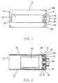
- Figure 1 illustrates a tubular housing for a miniature electric motor with an end cap fitted to one end in accordance with an embodiment of the present invention;
- Figure 2 is a cross-sectional view of the housing and end cap of Figure 1;
- Figure 3 is an end view of the housing and end cap of Figure 1; and
- Figure 4 is a cross-sectional view of the end cap of Figure 1.
-
- The
housing 10 is a tubular body of electrical steel which may be rolled or deep drawn. The housing has a substantially circular cross-section with twoflat sides 12. At each end of each flat side, a T-shaped hole 14 is formed producing a pair of circumferentially extendingfingers 16. Thefingers 16 have a tapered axiallyinner edge 18. Thesefingers 16 are used to secure anend cap 20 to the housing. As shown in Figure 2, thehousing 10 supportspermanent magnets 22 forming the stator field for a motor. - While only one end cap is shown in the drawings, the housing illustrated would have an end cap at each end, one supporting a bearing 24 (as shown in Fig. 2) and the other supporting a bearing and brush gear including motor terminals (not shown).
- The
end cap 20 has aflange 26 which sits on the end of the housing as well as aboss portion 28 which fits inside thehousing 10 and extends axially beyond the T-shaped holes 14. Tworecesses 30 in theflange 26 andboss 28 are aligned with the pairs offingers 16 and thefingers 16 are radially deformed into the recesses to secure the end cap to the housing. - Each
recess 30 has a circumferentially extending axially projecting outer lip orridge 32 which is engaged by thefingers 16. Indeed, thefingers 16 may deform or partly destroy theridge 32 when they are pressed into therecess 30. As the fingers engage the ridge, thetapered edge 18 of thefingers 16 apply an axial force pressing the end cap into tight contact with the housing. The more thefingers 16 are pressed radially, the greater the axial force applied to theend cap 20. Thus, even if there is slight springback of thefingers 16 in the radial direction, the axial clamping force will remain resulting in no loosening of the end cap. - The use of the
ridge 32 allows for slight variation in axial alignment between thefingers 16 and therecesses 30 due to manufacturing tolerances, etc. without affecting the holding force. Theridge 32 can be readily sheared radially by thefingers 16 while providing a strong axial abutment, the area behind the ridge providing a debris collection zone whereby the sheared portion of the ridge does not interfere with the radial deformation of the fingers. - The embodiment shown uses a resin moulded end cap which is preferred by some applications and the ridge in the recess for the locking fingers is easy to mould. However, end caps can be made from metal, either cast or stamped and such end caps can be formed with ridges in the engagement regions which are equivalent to recesses in the moulded end caps. While it is acknowledged that resin can be sheared more easily than metal, particularly mild steel, the ridge can nevertheless be deformed to accommodate the locking fingers and can achieve a good clamping pressure or resiliency.
- While the tapered locking fingers are preferred, to give increased compression or clamping force on the end cap, the ridge can be used with straight sided fingers to give satisfactory results by shearing or deforming the ridge. A chamfer on the ridge goes some way to increase the clamping force for a straight edged finger but is also beneficial for tapered fingers.
- As such, the present invention provides a very effective yet simple method of securely clamping an end cap to a housing of an electric motor even when the housing has a relatively thick wall making axial crimping impractical.
- While only one embodiment has been described, variations will be apparent to those skilled in the art and it is intended to cover all variations which fall within the scope of the invention as defined by the appended claims. In particular, although the fingers are shown formed in pairs, they could be formed individually. Also while two pairs of fingers are shown for holding one end cap, arrangements can be envisaged where there is only one finger or one pair of fingers is required to secure the end cap. Alternatively, three, four or more fingers or pairs of fingers could be used.
Claims (13)
- A miniature electric motor comprisingcharacterised in that the engagement portion is a recess (30) and includes an axially projecting ridge (32) at a radially outer edge of the recess (30), in that the finger (16) extends beyond the ridge (32) and into the recess (30) and in that an axially inner edge (18) of the finger (16) bears axially onto the ridge (32) to nip the end cap (20) to the housing (10).a tubular housing (10); andat least one end cap (20), said end cap (20) having a boss portion (28) fitted inside the housing (10), a flange (26) which abuts an axial end of the housing (10), and an engagement portion;said housing (10) having at least one finger (16) which extends in a plane perpendicular to the axis of the housing (10) and which is radially deformed into contact with the engagement portion of the end cap (20) to capture the end cap (20) to the housing (10);
- A motor according to claim 1, wherein the ridge (30) is substantially circumferentially extending along the engagement portion.
- A motor according to claim 1 or 2, wherein the engagement portion has a substantially planar portion lying in a radial plane of the motor from which the ridge (30) projects axially away from the housing (10).
- A motor according to claim 1, 2 or 3, wherein the end cap (20) is a moulded resin body.
- A motor according to any one of the preceding claims wherein the ridge (32) has an outer chamfer for guiding the finger (16).
- A motor according to any one of the preceding claims wherein the engagement between the ridge (32) and the finger (16) involves at least part shearing of the ridge (32) to accept the finger (16).
- A motor according to any one of the preceding claims, wherein the inner edge (18) of each finger (16) is tapered with respect to a radial plane of the motor.
- A motor according to any one of the preceding claims, wherein the housing (10) has an even number of fingers (16) formed as opposing pairs by T-shaped holes (14) in an end portion of the housing (10).
- A motor according to claim 8, wherein the end cap (20) has a number of engagement portions corresponding in number to the pairs of fingers (16) and the or each engagement portion accommodates one pair of fingers (16).
- A method of connecting an end cap (20) to a tubular housing (10) of a miniature electric motor, the method comprising the steps ofcharacterised by the engagement portion being a recess having an axially projecting ridge (32) at a radially outer edge of the recess (30) in the end cap (20) and by deforming the finger (16) radially so that the finger (16) extends beyond the ridge (32) and into the recess (30) and so that an axially inner edge (18) of the finger (16) axially engages the ridge (32) to prevent axial movement of the end cap (20) with respect to the housing (10).providing an end cap (20) with a flange (26), a boss portion (28) and at least one engagement portion,providing a tubular housing (10) with at least one finger (16) which extends in a plane perpendicular to the axis of the housing (10),inserting the boss portion (28) of the end cap (20) into the housing (10) such that the flange (26) abuts an axial end of the housing (10),
- A method according to claim 10, wherein the step of deforming the finger (16) includes shearing a part of the ridge (32) thereby firmly holding the end cap (20) to the housing (10).
- A method according to claim 10 or 11, including the step of providing a tapered surface (18) to the axially inner edge of the finger (16) thus causing a greater axial holding force the more the finger (16) is deformed radially.
- A method according to claim 10 or 11, including the steps ofproviding two pairs of said fingers (16) and radially deforming each pair of fingers into a respective engagement portion of the end cap (20), each finger (16) having an axially inner edge (18) which extends at an incline to a plane perpendicular to an axis of the housing (10), the axially inner edge (18) being brought into contact with the ridge (32) by radially deforming and continuing to radially deform the finger causing the inner edge of the finger to exert an axial force on the ridge (32) to clamp the end cap (20) to the housing (10).
Applications Claiming Priority (2)
| Application Number | Priority Date | Filing Date | Title |
|---|---|---|---|
| GB0104212 | 2001-02-21 | ||
| GBGB0104212.6A GB0104212D0 (en) | 2001-02-21 | 2001-02-21 | Motor casing |
Publications (2)
| Publication Number | Publication Date |
|---|---|
| EP1237255A1 EP1237255A1 (en) | 2002-09-04 |
| EP1237255B1 true EP1237255B1 (en) | 2004-01-21 |
Family
ID=9909165
Family Applications (1)
| Application Number | Title | Priority Date | Filing Date |
|---|---|---|---|
| EP02251060A Expired - Lifetime EP1237255B1 (en) | 2001-02-21 | 2002-02-15 | Motor casing |
Country Status (6)
| Country | Link |
|---|---|
| US (1) | US6700254B2 (en) |
| EP (1) | EP1237255B1 (en) |
| CN (1) | CN1248389C (en) |
| DE (1) | DE60200172T2 (en) |
| ES (1) | ES2214463T3 (en) |
| GB (1) | GB0104212D0 (en) |
Families Citing this family (20)
| Publication number | Priority date | Publication date | Assignee | Title |
|---|---|---|---|---|
| KR100461739B1 (en) * | 2002-10-14 | 2004-12-16 | 주식회사 에스 피 지 | Structure for housing geared motor |
| DE502005003461D1 (en) * | 2005-05-11 | 2008-05-08 | Vdo Automotive Ag | Electric machine with support of the rotor on one end face of the stator |
| DE102006026593B4 (en) | 2006-05-31 | 2010-04-08 | Getrag Getriebe-Und Zahnradfabrik Hermann Hagenmeyer Gmbh & Cie Kg | Electric synchronous machine |
| CN100529349C (en) * | 2007-09-19 | 2009-08-19 | 无锡开普动力有限公司 | Wind-cooling generating set end shield assembly with exhausting passage |
| JP2009240068A (en) * | 2008-03-27 | 2009-10-15 | Mabuchi Motor Co Ltd | Motor with case lid fixing structure |
| DE102009010085B3 (en) | 2009-02-24 | 2010-07-01 | Saia-Burgess Dresden Gmbh | A linear actuator |
| CN101877509A (en) * | 2009-04-29 | 2010-11-03 | 鸿富锦精密工业(深圳)有限公司 | Voice coil motor anti-electromagnetic interference shell structure |
| JP2013138545A (en) * | 2011-12-28 | 2013-07-11 | Nisca Corp | Motor |
| CN103670894A (en) * | 2012-09-20 | 2014-03-26 | 江苏恒威机械制造有限公司 | End cover enhanced connection structure of hydraulic motor |
| CN202978514U (en) * | 2012-11-29 | 2013-06-05 | 中山大洋电机制造有限公司 | An assembly structure of motor end cover and casing |
| JP2015136285A (en) * | 2013-12-17 | 2015-07-27 | パナソニックIpマネジメント株式会社 | AC commutator motor, electric blower, and electric device including electric blower |
| CN104295372B (en) * | 2014-10-15 | 2016-10-05 | 福建永强力加动力设备有限公司 | Decorative panel after generating set |
| CN204858809U (en) * | 2015-08-15 | 2015-12-09 | 中山大洋电机股份有限公司 | A DC brushless motor |
| WO2016155271A1 (en) | 2015-03-31 | 2016-10-06 | 中山大洋电机股份有限公司 | Direct-current brushless motor |
| EP3125408A1 (en) * | 2015-07-30 | 2017-02-01 | Siemens Aktiengesellschaft | Rotary machine having a connection device at housing sections, and their use for these |
| EP3453101B1 (en) * | 2016-05-04 | 2021-01-13 | Brose Fahrzeugteile SE & Co. Kommanditgesellschaft, Würzburg | Method for producing a pole housing |
| US11088587B2 (en) * | 2016-10-26 | 2021-08-10 | Nidec Sankyo Corporation | Motor |
| EP3322075B1 (en) * | 2016-11-11 | 2021-08-11 | Agie Charmilles SA | Linear shaft motor |
| CN111600455A (en) * | 2019-02-21 | 2020-08-28 | 三赢科技(深圳)有限公司 | Voice coil motor and camera module and electronic device using same |
| TWI883361B (en) * | 2022-12-15 | 2025-05-11 | 恆達智能科技股份有限公司 | Composite-type motor casing structure and manufacturing method thereof |
Family Cites Families (12)
| Publication number | Priority date | Publication date | Assignee | Title |
|---|---|---|---|---|
| US2701318A (en) * | 1952-11-22 | 1955-02-01 | Gen Electric | Dynamoelectric machine casing |
| US3732616A (en) * | 1968-06-26 | 1973-05-15 | Universal Electric Co | Method of making end frame structures for electric motors |
| US3567973A (en) | 1968-06-26 | 1971-03-02 | Universal Electric Co | Electric motors |
| BE758737A (en) | 1969-11-11 | 1971-04-16 | Gutris Giorgio | METHOD FOR ASSEMBLING ELECTRIC MOTORS, AND MOTORS MOUNTED ACCORDING TO THIS METHOD |
| US3600615A (en) * | 1970-01-19 | 1971-08-17 | Tarou Morita | Miniature motor |
| DE3302532A1 (en) | 1983-01-26 | 1984-07-26 | SWF-Spezialfabrik für Autozubehör Gustav Rau GmbH, 7120 Bietigheim-Bissingen | HOUSING, ESPECIALLY FOR AN ELECTRIC MOTOR, AND METHOD FOR THE PRODUCTION THEREOF |
| US4644204A (en) * | 1985-12-06 | 1987-02-17 | Fasco Industries, Inc. | Motor housing and end shield mount |
| DE3729574A1 (en) * | 1987-09-04 | 1989-03-16 | Licentia Gmbh | LOW POWER ELECTRIC MOTOR |
| JPH0615501Y2 (en) * | 1988-07-15 | 1994-04-20 | アスモ株式会社 | Small motor |
| DE4138705C2 (en) | 1991-11-26 | 1994-12-15 | Licentia Gmbh | Housing, in particular for small electrical machines |
| FR2723491B1 (en) * | 1994-08-04 | 1996-10-18 | Valeo Systemes Dessuyage | ROTATING MACHINE WITH EXTERNAL BEARINGS |
| FR2726700B1 (en) * | 1994-11-07 | 1997-01-10 | Valeo Systemes Dessuyage | ELECTRIC MOTOR WITH MANIFOLD IN WHICH THE COALS ARE SAID RELIABLY RELATIVE TO THE POLES OF THE STATOR |
-
2001
- 2001-02-21 GB GBGB0104212.6A patent/GB0104212D0/en not_active Ceased
-
2002
- 2002-02-15 ES ES02251060T patent/ES2214463T3/en not_active Expired - Lifetime
- 2002-02-15 EP EP02251060A patent/EP1237255B1/en not_active Expired - Lifetime
- 2002-02-15 DE DE2002600172 patent/DE60200172T2/en not_active Expired - Lifetime
- 2002-02-20 US US10/077,974 patent/US6700254B2/en not_active Expired - Lifetime
- 2002-02-21 CN CN02108490.4A patent/CN1248389C/en not_active Expired - Lifetime
Also Published As
| Publication number | Publication date |
|---|---|
| CN1373545A (en) | 2002-10-09 |
| US20020113506A1 (en) | 2002-08-22 |
| DE60200172D1 (en) | 2004-02-26 |
| EP1237255A1 (en) | 2002-09-04 |
| DE60200172T2 (en) | 2004-11-18 |
| US6700254B2 (en) | 2004-03-02 |
| ES2214463T3 (en) | 2004-09-16 |
| CN1248389C (en) | 2006-03-29 |
| GB0104212D0 (en) | 2001-04-11 |
Similar Documents
| Publication | Publication Date | Title |
|---|---|---|
| EP1237255B1 (en) | Motor casing | |
| CN106961171B (en) | Rotor, motor, method for manufacturing rotor, and method for manufacturing motor | |
| JP4730415B2 (en) | L-type coaxial connector | |
| US8342894B2 (en) | Terminal fitting | |
| EP0917247B1 (en) | Coaxial cable connector assembly | |
| US7576461B2 (en) | Electric motor | |
| JP2001251795A (en) | Permanent magnet rotor | |
| CN109980370B (en) | Connector | |
| JPH05284677A (en) | Stator core of electric rotating machine | |
| JP3094138B2 (en) | Barrel terminal and wire connection device | |
| JPH05219668A (en) | Permanent magnet type rotor | |
| JP3478022B2 (en) | Male terminal fitting | |
| JPH08273729A (en) | Contact and manufacturing method thereof | |
| JPH0946946A (en) | Magnet rotator | |
| JP4319801B2 (en) | Fixing method of screw device to metal plate | |
| JP2003051351A (en) | Male contact and method of manufacturing the same | |
| JP2002064958A (en) | Commutator, method for manufacturing commutator, and fuel pump | |
| JP3710667B2 (en) | Magnet cover fixing structure of rotating electric machine | |
| JPH11234940A (en) | Stator for electric motor | |
| JPH06105505A (en) | Magnet rotor manufacturing method | |
| JPH10302857A (en) | Electrical connector | |
| JP3531660B2 (en) | Caulking structure of laminated core | |
| JPH0224109B2 (en) | ||
| JP3452595B2 (en) | Magnet rotor | |
| JP3390568B2 (en) | Brush device for small motor |
Legal Events
| Date | Code | Title | Description |
|---|---|---|---|
| PUAI | Public reference made under article 153(3) epc to a published international application that has entered the european phase |
Free format text: ORIGINAL CODE: 0009012 |
|
| AK | Designated contracting states |
Kind code of ref document: A1 Designated state(s): AT BE CH CY DE DK ES FI FR GB GR IE IT LI LU MC NL PT SE TR |
|
| AX | Request for extension of the european patent |
Free format text: AL;LT;LV;MK;RO;SI |
|
| 17P | Request for examination filed |
Effective date: 20030124 |
|
| AKX | Designation fees paid |
Designated state(s): DE ES FR GB IT |
|
| 17Q | First examination report despatched |
Effective date: 20030423 |
|
| GRAP | Despatch of communication of intention to grant a patent |
Free format text: ORIGINAL CODE: EPIDOSNIGR1 |
|
| GRAS | Grant fee paid |
Free format text: ORIGINAL CODE: EPIDOSNIGR3 |
|
| GRAA | (expected) grant |
Free format text: ORIGINAL CODE: 0009210 |
|
| AK | Designated contracting states |
Kind code of ref document: B1 Designated state(s): DE ES FR GB IT |
|
| REG | Reference to a national code |
Ref country code: GB Ref legal event code: FG4D |
|
| REG | Reference to a national code |
Ref country code: IE Ref legal event code: FG4D |
|
| REF | Corresponds to: |
Ref document number: 60200172 Country of ref document: DE Date of ref document: 20040226 Kind code of ref document: P |
|
| ET | Fr: translation filed | ||
| REG | Reference to a national code |
Ref country code: ES Ref legal event code: FG2A Ref document number: 2214463 Country of ref document: ES Kind code of ref document: T3 |
|
| REG | Reference to a national code |
Ref country code: IE Ref legal event code: MM4A |
|
| PLBE | No opposition filed within time limit |
Free format text: ORIGINAL CODE: 0009261 |
|
| STAA | Information on the status of an ep patent application or granted ep patent |
Free format text: STATUS: NO OPPOSITION FILED WITHIN TIME LIMIT |
|
| 26N | No opposition filed |
Effective date: 20041022 |
|
| PGFP | Annual fee paid to national office [announced via postgrant information from national office to epo] |
Ref country code: ES Payment date: 20090317 Year of fee payment: 8 |
|
| PGFP | Annual fee paid to national office [announced via postgrant information from national office to epo] |
Ref country code: GB Payment date: 20090211 Year of fee payment: 8 |
|
| PGFP | Annual fee paid to national office [announced via postgrant information from national office to epo] |
Ref country code: IT Payment date: 20090212 Year of fee payment: 8 |
|
| PGFP | Annual fee paid to national office [announced via postgrant information from national office to epo] |
Ref country code: FR Payment date: 20090213 Year of fee payment: 8 |
|
| GBPC | Gb: european patent ceased through non-payment of renewal fee |
Effective date: 20100215 |
|
| REG | Reference to a national code |
Ref country code: FR Ref legal event code: ST Effective date: 20101029 |
|
| PG25 | Lapsed in a contracting state [announced via postgrant information from national office to epo] |
Ref country code: FR Free format text: LAPSE BECAUSE OF NON-PAYMENT OF DUE FEES Effective date: 20100301 |
|
| REG | Reference to a national code |
Ref country code: ES Ref legal event code: FD2A Effective date: 20110310 |
|
| PG25 | Lapsed in a contracting state [announced via postgrant information from national office to epo] |
Ref country code: GB Free format text: LAPSE BECAUSE OF NON-PAYMENT OF DUE FEES Effective date: 20100215 Ref country code: IT Free format text: LAPSE BECAUSE OF NON-PAYMENT OF DUE FEES Effective date: 20100215 |
|
| PG25 | Lapsed in a contracting state [announced via postgrant information from national office to epo] |
Ref country code: ES Free format text: LAPSE BECAUSE OF NON-PAYMENT OF DUE FEES Effective date: 20110309 |
|
| PG25 | Lapsed in a contracting state [announced via postgrant information from national office to epo] |
Ref country code: ES Free format text: LAPSE BECAUSE OF NON-PAYMENT OF DUE FEES Effective date: 20100216 |
|
| REG | Reference to a national code |
Ref country code: DE Ref legal event code: R081 Ref document number: 60200172 Country of ref document: DE Owner name: JOHNSON ELECTRIC INTERNATIONAL AG, CH Free format text: FORMER OWNER: JOHNSON ELECTRIC S.A., LA CHAUX-DE-FONDS, NEUENBURG, CH |
|
| PGFP | Annual fee paid to national office [announced via postgrant information from national office to epo] |
Ref country code: DE Payment date: 20210209 Year of fee payment: 20 |
|
| REG | Reference to a national code |
Ref country code: DE Ref legal event code: R071 Ref document number: 60200172 Country of ref document: DE |