EP1237235B1 - A planar carbon segment commutator - Google Patents
A planar carbon segment commutator Download PDFInfo
- Publication number
- EP1237235B1 EP1237235B1 EP02251329A EP02251329A EP1237235B1 EP 1237235 B1 EP1237235 B1 EP 1237235B1 EP 02251329 A EP02251329 A EP 02251329A EP 02251329 A EP02251329 A EP 02251329A EP 1237235 B1 EP1237235 B1 EP 1237235B1
- Authority
- EP
- European Patent Office
- Prior art keywords
- commutator
- base
- housing
- terminal
- recesses
- Prior art date
- Legal status (The legal status is an assumption and is not a legal conclusion. Google has not performed a legal analysis and makes no representation as to the accuracy of the status listed.)
- Expired - Lifetime
Links
- OKTJSMMVPCPJKN-UHFFFAOYSA-N Carbon Chemical compound [C] OKTJSMMVPCPJKN-UHFFFAOYSA-N 0.000 title claims abstract description 11
- 229910052799 carbon Inorganic materials 0.000 title claims abstract description 10
- 238000004804 winding Methods 0.000 claims abstract description 31
- 238000009413 insulation Methods 0.000 claims abstract description 13
- 238000005520 cutting process Methods 0.000 claims abstract description 10
- 239000011810 insulating material Substances 0.000 claims abstract description 3
- 239000000463 material Substances 0.000 claims description 11
- 238000004873 anchoring Methods 0.000 claims description 7
- 238000006073 displacement reaction Methods 0.000 claims description 2
- 238000000034 method Methods 0.000 description 8
- 230000000694 effects Effects 0.000 description 4
- 238000007731 hot pressing Methods 0.000 description 4
- 239000011230 binding agent Substances 0.000 description 3
- 239000007770 graphite material Substances 0.000 description 3
- 239000002184 metal Substances 0.000 description 3
- 229910052751 metal Inorganic materials 0.000 description 3
- 230000004907 flux Effects 0.000 description 2
- 239000000203 mixture Substances 0.000 description 2
- 238000000465 moulding Methods 0.000 description 2
- 230000003647 oxidation Effects 0.000 description 2
- 238000007254 oxidation reaction Methods 0.000 description 2
- KXGFMDJXCMQABM-UHFFFAOYSA-N 2-methoxy-6-methylphenol Chemical compound [CH]OC1=CC=CC([CH])=C1O KXGFMDJXCMQABM-UHFFFAOYSA-N 0.000 description 1
- RYGMFSIKBFXOCR-UHFFFAOYSA-N Copper Chemical compound [Cu] RYGMFSIKBFXOCR-UHFFFAOYSA-N 0.000 description 1
- 230000001133 acceleration Effects 0.000 description 1
- 238000013459 approach Methods 0.000 description 1
- 238000006243 chemical reaction Methods 0.000 description 1
- 239000011248 coating agent Substances 0.000 description 1
- 238000000576 coating method Methods 0.000 description 1
- 230000006835 compression Effects 0.000 description 1
- 238000007906 compression Methods 0.000 description 1
- 230000003628 erosive effect Effects 0.000 description 1
- 238000007716 flux method Methods 0.000 description 1
- 229910002804 graphite Inorganic materials 0.000 description 1
- 239000010439 graphite Substances 0.000 description 1
- WABPQHHGFIMREM-UHFFFAOYSA-N lead(0) Chemical compound [Pb] WABPQHHGFIMREM-UHFFFAOYSA-N 0.000 description 1
- 238000004519 manufacturing process Methods 0.000 description 1
- 238000012986 modification Methods 0.000 description 1
- 230000004048 modification Effects 0.000 description 1
- 239000005011 phenolic resin Substances 0.000 description 1
- 229920001568 phenolic resin Polymers 0.000 description 1
- 238000005245 sintering Methods 0.000 description 1
- 229910000679 solder Inorganic materials 0.000 description 1
- 229920001187 thermosetting polymer Polymers 0.000 description 1
Images

Classifications
-
- H—ELECTRICITY
- H01—ELECTRIC ELEMENTS
- H01R—ELECTRICALLY-CONDUCTIVE CONNECTIONS; STRUCTURAL ASSOCIATIONS OF A PLURALITY OF MUTUALLY-INSULATED ELECTRICAL CONNECTING ELEMENTS; COUPLING DEVICES; CURRENT COLLECTORS
- H01R39/00—Rotary current collectors, distributors or interrupters
- H01R39/02—Details for dynamo electric machines
- H01R39/04—Commutators
- H01R39/045—Commutators the commutators being made of carbon
-
- H—ELECTRICITY
- H01—ELECTRIC ELEMENTS
- H01R—ELECTRICALLY-CONDUCTIVE CONNECTIONS; STRUCTURAL ASSOCIATIONS OF A PLURALITY OF MUTUALLY-INSULATED ELECTRICAL CONNECTING ELEMENTS; COUPLING DEVICES; CURRENT COLLECTORS
- H01R39/00—Rotary current collectors, distributors or interrupters
- H01R39/02—Details for dynamo electric machines
- H01R39/04—Commutators
- H01R39/06—Commutators other than with external cylindrical contact surface, e.g. flat commutators
-
- H—ELECTRICITY
- H01—ELECTRIC ELEMENTS
- H01R—ELECTRICALLY-CONDUCTIVE CONNECTIONS; STRUCTURAL ASSOCIATIONS OF A PLURALITY OF MUTUALLY-INSULATED ELECTRICAL CONNECTING ELEMENTS; COUPLING DEVICES; CURRENT COLLECTORS
- H01R39/00—Rotary current collectors, distributors or interrupters
- H01R39/02—Details for dynamo electric machines
- H01R39/32—Connections of conductor to commutator segment
-
- H—ELECTRICITY
- H01—ELECTRIC ELEMENTS
- H01R—ELECTRICALLY-CONDUCTIVE CONNECTIONS; STRUCTURAL ASSOCIATIONS OF A PLURALITY OF MUTUALLY-INSULATED ELECTRICAL CONNECTING ELEMENTS; COUPLING DEVICES; CURRENT COLLECTORS
- H01R4/00—Electrically-conductive connections between two or more conductive members in direct contact, i.e. touching one another; Means for effecting or maintaining such contact; Electrically-conductive connections having two or more spaced connecting locations for conductors and using contact members penetrating insulation
- H01R4/24—Connections using contact members penetrating or cutting insulation or cable strands
- H01R4/2416—Connections using contact members penetrating or cutting insulation or cable strands the contact members having insulation-cutting edges, e.g. of tuning fork type
- H01R4/242—Connections using contact members penetrating or cutting insulation or cable strands the contact members having insulation-cutting edges, e.g. of tuning fork type the contact members being plates having a single slot
- H01R4/2437—Curved plates
-
- H—ELECTRICITY
- H01—ELECTRIC ELEMENTS
- H01R—ELECTRICALLY-CONDUCTIVE CONNECTIONS; STRUCTURAL ASSOCIATIONS OF A PLURALITY OF MUTUALLY-INSULATED ELECTRICAL CONNECTING ELEMENTS; COUPLING DEVICES; CURRENT COLLECTORS
- H01R43/00—Apparatus or processes specially adapted for manufacturing, assembling, maintaining, or repairing of line connectors or current collectors or for joining electric conductors
- H01R43/06—Manufacture of commutators
Definitions
- This invention relates to a planar carbon segment commutator for use with brushes which bear axially against planar contact surfaces of the commutator, instead of bearing radially as in the case of a cylindrical commutator.
- Heat causes embrittlement of the copper wire which is used for most armature windings and encourages rapid oxidation.
- the use of heat also demands a strong structure to support the commutator in order to minimise plastic distortion. This requirement usually demands the use of high temperature compression grade moulding material.
- a further common problem is caused by the accidental stripping of insulation during winding of the armature which is often automated. As the wire passes over the metal of the commutator damage can be caused to the wire insulation and such damage will often be manifest as a short circuited winding. Additionally, there is always a danger of slack in the winding wire causing fretting under the acceleration due to centrifugal and inertial forces.
- a planar carbon segment commutator comprising a commutator base of insulating material, the base having a rotational axis, front and rear surfaces, extending, at least in part, transversely to the rotational axis, and a plurality of first apertures extending through the base, a plurality of commutator terminals each of which comprises a terminal portion and a contact portion, the contact portion of each terminal extending through a respective first aperture in the base and being bent to lie against or in close proximity to the front surface of the base and the terminal portion of each terminal having two cutting edges for cutting insulation on a connector portion of a winding and a slot which in use straddles and grips said connector portion, and a plurality of carbon segments formed on the front surface of the base and over the contact portions, respectively, of the terminals.
- the commutator includes a housing having a plurality of housing recesses for receiving respective terminal portions.
- each housing recess has associated therewith means for positioning connector portions of the winding relative to each recess, the base, the terminals and the housing being such that with a single translational movement of the base relative to the housing, the terminal portions enter the housing recesses, the cutting edges strip insulation from connector portions of the winding and the slots establish and maintain electrical contact with connector portions of the winding by insulation displacement.
- the base has a cylindrical skirt extending rearwardly of its rear surface for receiving the housing.
- the front surface of the base has a plurality of recesses and each contact portion overlies a respective recess and has at least one aperture through which material forming a respective commutator segment extends into the recess to assist in anchoring the segment to the terminal.
- the base has a plurality of second apertures communicating with the recesses and through which material forming the commutator segments extends to assist in anchoring the segments to the base.
- the base has a plurality of third apertures through which material forming the commutator segments extends to assist in anchoring the commutator segments to the base.
- the commutator shown in the drawings is intended for use with small electric motors, particularly permanent magnet dc motors.
- the commutator base 10 shown therein is of moulded material and comprises a circular front wall 11 and a cylindrical skirt 12 extending rearwardly from the front wall 11.
- the base 10 also has a central boss 13 by which the base 10 can be fitted to an armature shaft (not shown).
- a plurality of circumferentially spaced axially extending ribs 14 are provided on the inner surface of the skirt 12, for a purpose that will be explained later.
- the front wall 11 has a central aperture 45 aligned with the boss 13, eight, equi-angularly spaced, elongate radially extending recesses 15 and an elongate, slit-like, aperture 16 radially aligned with each recess 15.
- Each recess 15 communicates at its radially inner end with an aperture 17.
- Each recess 15 is also associated with two apertures 18, one on either side of a respective recess 15 and adjacent its radially outer end.
- the front wall 11 also has an outer ring of angularly spaced apart slots 19.
- the commutator terminal 20 shown in Figures 7 and 8 comprises a terminal portion 21 and a contact portion 22.
- the contact portion 22 is in the form of a finger having three apertures 23, 24 and 25 therein.
- the terminal portion 21 is rectangular (as shown in developed view) with its minor axis coincident with the longitudinal axis of the contact portion 22.
- the terminal portion 21 has a central cut out portion 26 which is symmetrical with respect to both the major and minor axes of the terminal portion 21.
- the cut out portion 26 reduces from its largest width at the centre of the terminal portion 21 to two slots 27.
- Two cutters 28 project a short distance into each slot 27. These cutters 28 form sharp edges for cutting insulation on a connector portion of an armature winding.
- the terminal portion 21 also has two barbs 29 for a purpose which will become apparent later.
- the fingers 22 are pressed through respective apertures 16 in the base 10 and the fingers 22 are then bent over respective recesses 15 to extend radially inwards.
- Carbon commutator segments 30 are then formed on the front wall 11 of the commutator base 10 over the fingers 22. This may be achieved by hot pressing a disc of green graphite material onto the front wall 11 and then cutting the disc into eight individual segments 30.
- Green graphite material is a graphite mixture prior to sintering or heat treating during which the binder material is set. During the hot pressing, the binder is softened (possibly liquified) and this allows the mixture to flow under pressure through the apertures 23, 24 and 25 in the fingers 22 and into the recesses 15, into the slots 19 and through the apertures 17 and 18, as best shown in Figures 5 and 6, to anchor the disc to the base 10.
- the binder being of thermoset material such as phenolic resin, once melted and cooled becomes heat resistant, creating a stable contact surface for the commutator.
- an overmoulding process can be used. In this latter process, the components, namely the commutator base 10 and the terminals 20 are placed into a mould and graphite material is injected into the mould after the latter has been closed. The hot pressing or moulding process creates a good electrical connection with the fingers 22.
- a housing 35 for the terminal portions 21 of the terminals 20 This housing 35 is of crown-like shape and has a central boss 36 for receiving the armature shaft and eight radially outwardly extending housing portions 37 equally spaced around the circumference of the boss 36. Each of the housing portions 37 defines a housing recess 38 and is used to effect connection between a respective portion of the armature winding and one of the terminal portions 21 of the terminals 20. Each housing portion 37 has side walls 39, an end wall 40, and a cover 41. The side walls 39 are parallel to the longitudinal axis of the boss 36.
- a stump 42 projects centrally from the internal surface of the end wall 40 and extends within the housing portion 37 for approximately half the length of the side walls 39.
- the stump 42 extends parallel with the longitudinal axis of the boss 36 and is only connected to the housing 35 by the end wall 40.
- Each side wall 39 has a slot 43 which extends parallel to the longitudinal axis of the boss 36, from the commutator end of the housing 35 for a length which terminates at the level of the free end of the stump 42.
- a portion of an armature winding can be passed through the slots 43 so that the winding portion rests on the end of the stump.
- the housing 35 is placed on the armature shaft.
- the lead wire of the armature winding is inserted into one of the housing portions 37 by laying the end of the wire in the slots 43 provided in the side walls 39.
- the wire is drawn back into the housing portion 37 until it rests against the stump 42. From this start, the first armature coil is wound. At the end of the first coil winding, the armature is indexed and the wire is laid in the same manner in the next housing portion 37 without breaking the continuity of the wire.
- the housing 35 now has a winding portion comprising insulated wire laying in each of the housing portions 37.
- Each of the winding portions is under tension and is pulled tight against the respective stump 42.
- the commutator base 10, together with the terminals 20 and commutator segments 30, is then slid along the armature shaft so that the terminal portions 21 of the terminals enter respective housing portions 37 and the housing portions lie between the ribs 14.
- the slots 27 move over the wire.
- the cutters 28 severe the insulation on the wire which is deformed as the slots move over the wire. Intimate metal to metal contact is thereby provided between the wire and the terminal portions 20.
- the barbs 29 grip the cover 41 of the housing 35 and therefore retain the terminal portions 21 within the housing 35.
Landscapes
- Motor Or Generator Current Collectors (AREA)
- Insulation, Fastening Of Motor, Generator Windings (AREA)
- Inert Electrodes (AREA)
- Carbon And Carbon Compounds (AREA)
- Manufacture Of Switches (AREA)
- Rotary Switch, Piano Key Switch, And Lever Switch (AREA)
- Switch Cases, Indication, And Locking (AREA)
- Dc Machiner (AREA)
Abstract
Description
- This invention relates to a planar carbon segment commutator for use with brushes which bear axially against planar contact surfaces of the commutator, instead of bearing radially as in the case of a cylindrical commutator.
- It is known, for example from
EP 0583892 , to provide a planar commutator in which a plurality of commutator terminals are mounted on a commutator base and overmoulded with carbon segments. However, the terminals of these known planar commutators each have tangs to which the armature winding of an electric motor has to be connected. - A number of known methods for effecting such connections are in popular use. Where the winding is formed of low temperature wire, it is usual to employ a soft solder and flux method. Alternatively a cold crimp onto wire that has been stripped of insulation is used in order effect a connection. When dealing with high temperature wires it is necessary to apply heat, and also possibly to apply flux so as to remove the coating of insulation from the ends of the wire.
- However, there are a number of inherent problems and undesirable side effects associated with all of the foregoing methods.
- Heat causes embrittlement of the copper wire which is used for most armature windings and encourages rapid oxidation. The use of heat also demands a strong structure to support the commutator in order to minimise plastic distortion. This requirement usually demands the use of high temperature compression grade moulding material. A further common problem is caused by the accidental stripping of insulation during winding of the armature which is often automated. As the wire passes over the metal of the commutator damage can be caused to the wire insulation and such damage will often be manifest as a short circuited winding. Additionally, there is always a danger of slack in the winding wire causing fretting under the acceleration due to centrifugal and inertial forces.
- According to the present invention there is provided a planar carbon segment commutator comprising a commutator base of insulating material, the base having a rotational axis, front and rear surfaces, extending, at least in part, transversely to the rotational axis, and a plurality of first apertures extending through the base, a plurality of commutator terminals each of which comprises a terminal portion and a contact portion, the contact portion of each terminal extending through a respective first aperture in the base and being bent to lie against or in close proximity to the front surface of the base and the terminal portion of each terminal having two cutting edges for cutting insulation on a connector portion of a winding and a slot which in use straddles and grips said connector portion, and a plurality of carbon segments formed on the front surface of the base and over the contact portions, respectively, of the terminals.
- Preferably, the commutator includes a housing having a plurality of housing recesses for receiving respective terminal portions.
- Preferably, each housing recess has associated therewith means for positioning connector portions of the winding relative to each recess, the base, the terminals and the housing being such that with a single translational movement of the base relative to the housing, the terminal portions enter the housing recesses, the cutting edges strip insulation from connector portions of the winding and the slots establish and maintain electrical contact with connector portions of the winding by insulation displacement.
- Preferably, the base has a cylindrical skirt extending rearwardly of its rear surface for receiving the housing.
- Preferably, the front surface of the base has a plurality of recesses and each contact portion overlies a respective recess and has at least one aperture through which material forming a respective commutator segment extends into the recess to assist in anchoring the segment to the terminal.
- Preferably, the base has a plurality of second apertures communicating with the recesses and through which material forming the commutator segments extends to assist in anchoring the segments to the base.
- Preferably, the base has a plurality of third apertures through which material forming the commutator segments extends to assist in anchoring the commutator segments to the base.
- The invention will now be more particularly described, by way of example, with reference to the accompanying drawings, in which:-
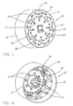
- Figure 1 is a perspective view from the front and side of a commutator base of one embodiment of a planar commutator according to a first aspect of the invention;
- Figure 2 is a perspective view from the rear and one side of the commutator base shown in Figure 1;
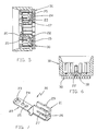
- Figure 3 is a plan view of the assembled commutator;
- Figure 4 is an underneath plan view of the assembled commutator;
- Figure 5 is a section taken along the line A - A of Figure 3;
- Figure 6 is a section taken along the line B - B of Figure 4;
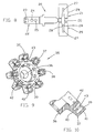
- Figure 7 is a perspective view of a commutator terminal on an enlarged scale;
- Figure 8 is a developed view of the terminal shown in Figure 7;
- Figure 9 is a perspective view of a housing for the terminals; and
- Figure 10 is a fragmentary sectional view of part of the housing of Figure 9.
- The commutator shown in the drawings is intended for use with small electric motors, particularly permanent magnet dc motors.
- Referring firstly to Figures 1 and 2, the
commutator base 10 shown therein is of moulded material and comprises acircular front wall 11 and acylindrical skirt 12 extending rearwardly from thefront wall 11. Thebase 10 also has acentral boss 13 by which thebase 10 can be fitted to an armature shaft (not shown). - A plurality of circumferentially spaced axially extending
ribs 14 are provided on the inner surface of theskirt 12, for a purpose that will be explained later. - The
front wall 11 has acentral aperture 45 aligned with theboss 13, eight, equi-angularly spaced, elongate radially extendingrecesses 15 and an elongate, slit-like,aperture 16 radially aligned with eachrecess 15. - Each
recess 15 communicates at its radially inner end with anaperture 17. - Each
recess 15 is also associated with twoapertures 18, one on either side of arespective recess 15 and adjacent its radially outer end. - The
front wall 11 also has an outer ring of angularly spaced apartslots 19. - The
commutator terminal 20 shown in Figures 7 and 8 comprises aterminal portion 21 and acontact portion 22. Thecontact portion 22 is in the form of a finger having threeapertures terminal portion 21 is rectangular (as shown in developed view) with its minor axis coincident with the longitudinal axis of thecontact portion 22. Theterminal portion 21 has a central cut outportion 26 which is symmetrical with respect to both the major and minor axes of theterminal portion 21. The cut outportion 26 reduces from its largest width at the centre of theterminal portion 21 to twoslots 27. Twocutters 28 project a short distance into eachslot 27. Thesecutters 28 form sharp edges for cutting insulation on a connector portion of an armature winding. Theterminal portion 21 also has twobarbs 29 for a purpose which will become apparent later. - To assemble the
terminals 20 to thebase 10, thefingers 22 are pressed throughrespective apertures 16 in thebase 10 and thefingers 22 are then bent overrespective recesses 15 to extend radially inwards. -
Carbon commutator segments 30 are then formed on thefront wall 11 of thecommutator base 10 over thefingers 22. This may be achieved by hot pressing a disc of green graphite material onto thefront wall 11 and then cutting the disc into eightindividual segments 30. Green graphite material is a graphite mixture prior to sintering or heat treating during which the binder material is set. During the hot pressing, the binder is softened (possibly liquified) and this allows the mixture to flow under pressure through theapertures fingers 22 and into therecesses 15, into theslots 19 and through theapertures base 10. The binder, being of thermoset material such as phenolic resin, once melted and cooled becomes heat resistant, creating a stable contact surface for the commutator. As an alternative to the hot pressing process an overmoulding process can be used. In this latter process, the components, namely thecommutator base 10 and theterminals 20 are placed into a mould and graphite material is injected into the mould after the latter has been closed. The hot pressing or moulding process creates a good electrical connection with thefingers 22. - Referring now to Figures 9 and 10, there is shown therein a
housing 35 for theterminal portions 21 of theterminals 20. Thishousing 35 is of crown-like shape and has acentral boss 36 for receiving the armature shaft and eight radially outwardly extendinghousing portions 37 equally spaced around the circumference of theboss 36. Each of thehousing portions 37 defines ahousing recess 38 and is used to effect connection between a respective portion of the armature winding and one of theterminal portions 21 of theterminals 20. Eachhousing portion 37 hasside walls 39, anend wall 40, and acover 41. Theside walls 39 are parallel to the longitudinal axis of theboss 36. - A
stump 42 projects centrally from the internal surface of theend wall 40 and extends within thehousing portion 37 for approximately half the length of theside walls 39. Thestump 42 extends parallel with the longitudinal axis of theboss 36 and is only connected to thehousing 35 by theend wall 40. Eachside wall 39 has aslot 43 which extends parallel to the longitudinal axis of theboss 36, from the commutator end of thehousing 35 for a length which terminates at the level of the free end of thestump 42. A portion of an armature winding can be passed through theslots 43 so that the winding portion rests on the end of the stump. - During assembly of the armature of an electric motor, the
housing 35 is placed on the armature shaft. The lead wire of the armature winding is inserted into one of thehousing portions 37 by laying the end of the wire in theslots 43 provided in theside walls 39. The wire is drawn back into thehousing portion 37 until it rests against thestump 42. From this start, the first armature coil is wound. At the end of the first coil winding, the armature is indexed and the wire is laid in the same manner in thenext housing portion 37 without breaking the continuity of the wire. This process is repeated until all coils have been wound and the tail end of the winding is then laid in theslots 43 of thefirst housing portion 37 and pushed back until it is adjacent to the lead end which was placed against thestump 42 at the beginning of the winding operation. The wire is then cut and the armature removed from the winding machine. - The
housing 35 now has a winding portion comprising insulated wire laying in each of thehousing portions 37. Each of the winding portions is under tension and is pulled tight against therespective stump 42. Thecommutator base 10, together with theterminals 20 andcommutator segments 30, is then slid along the armature shaft so that theterminal portions 21 of the terminals enterrespective housing portions 37 and the housing portions lie between theribs 14. As eachterminal portion 21 approaches a winding portion held in ahousing portion 37, theslots 27 move over the wire. Thecutters 28 severe the insulation on the wire which is deformed as the slots move over the wire. Intimate metal to metal contact is thereby provided between the wire and theterminal portions 20. Thebarbs 29 grip thecover 41 of thehousing 35 and therefore retain theterminal portions 21 within thehousing 35. - This manner of manufacture of a commutator lends itself to an automated process. No application of heat is required and the associated risk of distorting the
housing 35 is therefore avoided. No embrittlement of the winding wire is caused and problems associated with oxidation are also avoided. The use of flux is negated and there is no chemical reaction or consequent erosion resulting from the connection. The armature winding can be a single continuous winding and the danger of introducing slack by breaking the winding to effect a connection to each coil can be avoided. - The above embodiment is given by way of example only and various modifications will be apparent to persons skilled in the art without departing from the scope of the invention as defined in the appended claims.
Claims (14)
- A planar carbon segment commutator comprising:a commutator base (10) of insulating material, the base (10) having a rotational axis and front (11) and rear surfaces extending, at least in part, transversely to the rotational axis;a plurality of commutator terminals (20) each of which comprises a terminal portion (21) and a contact portion (22); anda plurality of carbon segments (30) formed on the front surface (11) of the base (10) and over the contact portions (22), respectively, of the terminals,characterised in that the contact portion (22) of each terminal (20) extends through a respective first aperture (16) in the base (10) and is bent to lie against or in close proximity to the front surface (11) of the base, and the terminal portion (21) of each terminal (20) has a cutting edge (28) for cutting insulation on a connector portion of a winding and a slot (27) which, in use, straddles and grips said connector portion.
- A commutator as claimed in claim 1, further characterised by a housing (35) having a plurality of housing recesses (38) for receiving the terminal portions (21), respectively, of the terminals (20).
- A commutator as claimed in claim 2, wherein each housing recess (38) has associated therewith means (42, 43) for positioning a respective connector portion of the winding relative to each recess (38), the base (10), the terminals (20) and the housing (35) being such that with a single translational movement of the base (10) relative to the housing (35), the terminal portions (21) enter the housing recesses (38), the cutting edges (28) strip insulation from connector portions of the winding and the slots (27) establish and maintain electrical contact with connector portions of the winding by insulation displacement.
- A commutator as claimed in claim 2 or claim 3, characterised in that the base (10) has a cylindrical skirt (12) extending rearwardly of its rear surface for receiving the housing (35).
- A commutator as claimed in any one of the preceding claims, wherein the front surface (11) of the base (10) has therein a plurality of recesses (15) and each contact portion (22) overlies a respective recess (15) and has at least one aperture (23) through which material forming a respective commutator segment (30) extends into the recess (15) to assist in anchoring the segment (30) to the terminal (20).
- A commutator as claimed in claim 5, wherein the base (10) has a plurality of second apertures (17) communicating with respective recesses (15) and through which material forming the commutator segments (30) extends to assist in anchoring the segments (30) to the base (10).
- A commutator as claimed in claim 5 or claim 6, wherein the recesses (15) are elongate and extend radially of the base (10).
- A commutator as claimed in any one of claims 5 to 7, wherein the first apertures (16) are radially aligned with and outwardly disposed of the recesses (15), respectively.
- A commutator as claimed in any one of claims 5 to 8, wherein the base (10) has a plurality of third apertures (18) spaced from the recesses (15) and through which material forming commutator segments (30) extends to assist in anchoring the commutator segments (30) to the base (10).
- A commutator as claimed in claim 9, wherein there are two third apertures (18) associated with each one of the recesses (15), one on either side of a respective recess.
- A commutator as claimed in any one of claims 1 to 4, wherein the base (10) has a plurality of third apertures (18) and through which material forming commutator segments (30) extends to assist in anchoring the commutator segments (30) to the base (10).
- A commutator as claimed in any one of the preceding claims, wherein the base (10) has a central boss (13) with a central aperture for receiving an armature shaft.
- A commutator as claimed in claim 2, wherein the base (10) has a central boss (13) for receiving an armature shaft.
- A commutator as claimed in claim 13, wherein the housing (35) also has a central boss (36) coaxial with the central boss (13) of the base (10) for receiving the armature shaft.
Applications Claiming Priority (2)
| Application Number | Priority Date | Filing Date | Title |
|---|---|---|---|
| GBGB0104915.4A GB0104915D0 (en) | 2001-02-28 | 2001-02-28 | A planar carbon segment comutator |
| GB0104915 | 2001-02-28 |
Publications (3)
| Publication Number | Publication Date |
|---|---|
| EP1237235A2 EP1237235A2 (en) | 2002-09-04 |
| EP1237235A3 EP1237235A3 (en) | 2003-04-09 |
| EP1237235B1 true EP1237235B1 (en) | 2007-10-31 |
Family
ID=9909672
Family Applications (1)
| Application Number | Title | Priority Date | Filing Date |
|---|---|---|---|
| EP02251329A Expired - Lifetime EP1237235B1 (en) | 2001-02-28 | 2002-02-26 | A planar carbon segment commutator |
Country Status (12)
| Country | Link |
|---|---|
| US (1) | US6667565B2 (en) |
| EP (1) | EP1237235B1 (en) |
| JP (1) | JP4056261B2 (en) |
| CN (1) | CN1263204C (en) |
| AT (1) | ATE377276T1 (en) |
| BR (1) | BR0200523A (en) |
| CZ (1) | CZ2002725A3 (en) |
| DE (1) | DE60223187T2 (en) |
| ES (1) | ES2294080T3 (en) |
| GB (1) | GB0104915D0 (en) |
| MX (1) | MXPA02002083A (en) |
| PL (1) | PL352542A1 (en) |
Families Citing this family (10)
| Publication number | Priority date | Publication date | Assignee | Title |
|---|---|---|---|---|
| GB0211441D0 (en) * | 2002-05-18 | 2002-06-26 | Johnson Electric Sa | Improvements in or relating to commutators |
| US6891456B2 (en) * | 2002-06-10 | 2005-05-10 | Delphi Technologies, Inc. | Multi-pole electromagnetic motor apparatus and method of assembling |
| GB0319978D0 (en) | 2003-08-27 | 2003-10-01 | Johnson Electric Sa | A carbon segment commutator |
| DE102004052026B4 (en) | 2003-11-07 | 2015-08-27 | Totankako Co., Ltd. | collector |
| DE102005028791A1 (en) * | 2005-06-16 | 2006-12-28 | Kautt & Bux Gmbh | Plan commutator and method for producing a flat commutator |
| DE102006046669A1 (en) * | 2006-09-29 | 2008-04-03 | Robert Bosch Gmbh | Commutator has contact segments, dissociated from each other, forming commutator surface, where each of segments is soldered with mounting section of metallic segment support part, and segment is provided with hub body |
| JP5515426B2 (en) * | 2009-05-28 | 2014-06-11 | 日本電産株式会社 | motor |
| CN101924315B (en) * | 2009-06-16 | 2014-09-03 | 德昌电机(深圳)有限公司 | Commutator and manufacturing method thereof |
| DE102009057063A1 (en) * | 2009-12-04 | 2011-06-09 | Kolektor Group D.O.O. | Method for producing a flat commutator and flat commutator |
| FR3018012B1 (en) * | 2014-02-25 | 2017-10-13 | Valeo Equip Electr Moteur | DEVICE FOR CONNECTING A ROTATING ELECTRIC MACHINE AND USE OF SUCH A CONNECTION DEVICE IN AN ELECTRICAL POWER SUPPLY COMPRESSOR |
Family Cites Families (9)
| Publication number | Priority date | Publication date | Assignee | Title |
|---|---|---|---|---|
| GB2128818B (en) | 1982-10-11 | 1986-02-12 | Johnson Electric Ind Mfg | An armature |
| GB2199195A (en) | 1986-12-11 | 1988-06-29 | Johnson Electric Ind Mfg | A disc-type armature having insulating cutting correctors |
| DE4028420A1 (en) | 1990-09-07 | 1992-03-12 | Kautt & Bux Kg | PLANKOMMUTATOR AND METHOD FOR THE PRODUCTION THEREOF |
| GB9118086D0 (en) * | 1991-08-22 | 1991-10-09 | Johnson Electric Sa | A cylindrical carbon segment commutator |
| GB9208980D0 (en) | 1992-04-25 | 1992-06-10 | Johnson Electric Sa | An assembled commutator |
| US5679996A (en) | 1992-04-25 | 1997-10-21 | Johnson Electric S.A. | Assembled commutator |
| GB9217259D0 (en) * | 1992-08-14 | 1992-09-30 | Johnson Electric Sa | A planar carbon segment commutor |
| GB2286487A (en) | 1994-02-12 | 1995-08-16 | Johnson Electric Sa | Planar moulded carbon segment commutator |
| JP3741834B2 (en) | 1997-07-31 | 2006-02-01 | 株式会社富士カーボン製造所 | Flat carbon commutator and method for manufacturing the same |
-
2001
- 2001-02-28 GB GBGB0104915.4A patent/GB0104915D0/en not_active Ceased
-
2002
- 2002-02-26 ES ES02251329T patent/ES2294080T3/en not_active Expired - Lifetime
- 2002-02-26 AT AT02251329T patent/ATE377276T1/en not_active IP Right Cessation
- 2002-02-26 DE DE60223187T patent/DE60223187T2/en not_active Expired - Lifetime
- 2002-02-26 EP EP02251329A patent/EP1237235B1/en not_active Expired - Lifetime
- 2002-02-27 MX MXPA02002083A patent/MXPA02002083A/en active IP Right Grant
- 2002-02-27 CZ CZ2002725A patent/CZ2002725A3/en unknown
- 2002-02-27 US US10/083,389 patent/US6667565B2/en not_active Expired - Fee Related
- 2002-02-27 BR BR0200523-9A patent/BR0200523A/en not_active IP Right Cessation
- 2002-02-28 PL PL02352542A patent/PL352542A1/en unknown
- 2002-02-28 CN CN02105645.5A patent/CN1263204C/en not_active Expired - Fee Related
- 2002-02-28 JP JP2002053536A patent/JP4056261B2/en not_active Expired - Fee Related
Also Published As
| Publication number | Publication date |
|---|---|
| US6667565B2 (en) | 2003-12-23 |
| GB0104915D0 (en) | 2001-04-18 |
| CN1263204C (en) | 2006-07-05 |
| DE60223187T2 (en) | 2008-08-14 |
| BR0200523A (en) | 2002-10-01 |
| MXPA02002083A (en) | 2002-09-30 |
| JP2002315265A (en) | 2002-10-25 |
| ATE377276T1 (en) | 2007-11-15 |
| CZ2002725A3 (en) | 2003-03-12 |
| ES2294080T3 (en) | 2008-04-01 |
| EP1237235A2 (en) | 2002-09-04 |
| US20020117930A1 (en) | 2002-08-29 |
| EP1237235A3 (en) | 2003-04-09 |
| PL352542A1 (en) | 2002-09-09 |
| CN1373537A (en) | 2002-10-09 |
| JP4056261B2 (en) | 2008-03-05 |
| DE60223187D1 (en) | 2007-12-13 |
Similar Documents
| Publication | Publication Date | Title |
|---|---|---|
| US4656380A (en) | Commutator with winding connection segments having cutting edges | |
| EP1237235B1 (en) | A planar carbon segment commutator | |
| US7485998B2 (en) | Commutator | |
| US4930210A (en) | Method for assembling an electric motor armature | |
| EP0571072B1 (en) | An assembled commutator | |
| US5679996A (en) | Assembled commutator | |
| CN112217307A (en) | Stator of electric motor and method of manufacturing the same | |
| EP0271175B1 (en) | A commutator | |
| US4983871A (en) | Commutator with base alignment interlock | |
| GB2223888A (en) | Assembled commutator for electric motor | |
| US7057325B2 (en) | Carbon segment commutator | |
| EP0282671A1 (en) | A method of connecting an armature winding to a commutator segment | |
| EP0349142A1 (en) | An armature | |
| GB2202384A (en) | Connecting armature winding to commutator segments of an electric motor | |
| GB2204453A (en) | Connections between armature windings and commutator segments for an electric motor | |
| GB2203596A (en) | Winding connections retention in an armature for an electric motor |
Legal Events
| Date | Code | Title | Description |
|---|---|---|---|
| PUAI | Public reference made under article 153(3) epc to a published international application that has entered the european phase |
Free format text: ORIGINAL CODE: 0009012 |
|
| AK | Designated contracting states |
Kind code of ref document: A2 Designated state(s): AT BE CH CY DE DK ES FI FR GB GR IE IT LI LU MC NL PT SE TR |
|
| AX | Request for extension of the european patent |
Free format text: AL;LT;LV;MK;RO;SI |
|
| PUAL | Search report despatched |
Free format text: ORIGINAL CODE: 0009013 |
|
| AK | Designated contracting states |
Kind code of ref document: A3 Designated state(s): AT BE CH CY DE DK ES FI FR GB GR IE IT LI LU MC NL PT SE TR |
|
| AX | Request for extension of the european patent |
Extension state: AL LT LV MK RO SI |
|
| 17P | Request for examination filed |
Effective date: 20030922 |
|
| AKX | Designation fees paid |
Designated state(s): AT BE CH CY DE DK ES FI FR GB GR IE IT LI LU MC NL PT SE TR |
|
| GRAP | Despatch of communication of intention to grant a patent |
Free format text: ORIGINAL CODE: EPIDOSNIGR1 |
|
| RTI1 | Title (correction) |
Free format text: A PLANAR CARBON SEGMENT COMMUTATOR |
|
| GRAS | Grant fee paid |
Free format text: ORIGINAL CODE: EPIDOSNIGR3 |
|
| GRAA | (expected) grant |
Free format text: ORIGINAL CODE: 0009210 |
|
| AK | Designated contracting states |
Kind code of ref document: B1 Designated state(s): AT BE CH CY DE DK ES FI FR GB GR IE IT LI LU MC NL PT SE TR |
|
| REG | Reference to a national code |
Ref country code: GB Ref legal event code: FG4D |
|
| REG | Reference to a national code |
Ref country code: IE Ref legal event code: FG4D |
|
| REG | Reference to a national code |
Ref country code: CH Ref legal event code: EP |
|
| REF | Corresponds to: |
Ref document number: 60223187 Country of ref document: DE Date of ref document: 20071213 Kind code of ref document: P |
|
| NLV1 | Nl: lapsed or annulled due to failure to fulfill the requirements of art. 29p and 29m of the patents act | ||
| REG | Reference to a national code |
Ref country code: ES Ref legal event code: FG2A Ref document number: 2294080 Country of ref document: ES Kind code of ref document: T3 |
|
| PG25 | Lapsed in a contracting state [announced via postgrant information from national office to epo] |
Ref country code: NL Free format text: LAPSE BECAUSE OF FAILURE TO SUBMIT A TRANSLATION OF THE DESCRIPTION OR TO PAY THE FEE WITHIN THE PRESCRIBED TIME-LIMIT Effective date: 20071031 Ref country code: CH Free format text: LAPSE BECAUSE OF FAILURE TO SUBMIT A TRANSLATION OF THE DESCRIPTION OR TO PAY THE FEE WITHIN THE PRESCRIBED TIME-LIMIT Effective date: 20071031 Ref country code: SE Free format text: LAPSE BECAUSE OF FAILURE TO SUBMIT A TRANSLATION OF THE DESCRIPTION OR TO PAY THE FEE WITHIN THE PRESCRIBED TIME-LIMIT Effective date: 20080131 Ref country code: LI Free format text: LAPSE BECAUSE OF FAILURE TO SUBMIT A TRANSLATION OF THE DESCRIPTION OR TO PAY THE FEE WITHIN THE PRESCRIBED TIME-LIMIT Effective date: 20071031 |
|
| REG | Reference to a national code |
Ref country code: CH Ref legal event code: PL |
|
| PG25 | Lapsed in a contracting state [announced via postgrant information from national office to epo] |
Ref country code: PT Free format text: LAPSE BECAUSE OF FAILURE TO SUBMIT A TRANSLATION OF THE DESCRIPTION OR TO PAY THE FEE WITHIN THE PRESCRIBED TIME-LIMIT Effective date: 20080331 |
|
| PG25 | Lapsed in a contracting state [announced via postgrant information from national office to epo] |
Ref country code: AT Free format text: LAPSE BECAUSE OF FAILURE TO SUBMIT A TRANSLATION OF THE DESCRIPTION OR TO PAY THE FEE WITHIN THE PRESCRIBED TIME-LIMIT Effective date: 20071031 |
|
| ET | Fr: translation filed | ||
| PG25 | Lapsed in a contracting state [announced via postgrant information from national office to epo] |
Ref country code: DK Free format text: LAPSE BECAUSE OF FAILURE TO SUBMIT A TRANSLATION OF THE DESCRIPTION OR TO PAY THE FEE WITHIN THE PRESCRIBED TIME-LIMIT Effective date: 20071031 |
|
| PGFP | Annual fee paid to national office [announced via postgrant information from national office to epo] |
Ref country code: ES Payment date: 20080415 Year of fee payment: 7 |
|
| PG25 | Lapsed in a contracting state [announced via postgrant information from national office to epo] |
Ref country code: BE Free format text: LAPSE BECAUSE OF FAILURE TO SUBMIT A TRANSLATION OF THE DESCRIPTION OR TO PAY THE FEE WITHIN THE PRESCRIBED TIME-LIMIT Effective date: 20071031 |
|
| PLBE | No opposition filed within time limit |
Free format text: ORIGINAL CODE: 0009261 |
|
| STAA | Information on the status of an ep patent application or granted ep patent |
Free format text: STATUS: NO OPPOSITION FILED WITHIN TIME LIMIT |
|
| PGFP | Annual fee paid to national office [announced via postgrant information from national office to epo] |
Ref country code: IT Payment date: 20080430 Year of fee payment: 7 |
|
| 26N | No opposition filed |
Effective date: 20080801 |
|
| PG25 | Lapsed in a contracting state [announced via postgrant information from national office to epo] |
Ref country code: MC Free format text: LAPSE BECAUSE OF NON-PAYMENT OF DUE FEES Effective date: 20080228 |
|
| PGFP | Annual fee paid to national office [announced via postgrant information from national office to epo] |
Ref country code: FR Payment date: 20080414 Year of fee payment: 7 |
|
| PGFP | Annual fee paid to national office [announced via postgrant information from national office to epo] |
Ref country code: GB Payment date: 20080409 Year of fee payment: 7 |
|
| PG25 | Lapsed in a contracting state [announced via postgrant information from national office to epo] |
Ref country code: IE Free format text: LAPSE BECAUSE OF NON-PAYMENT OF DUE FEES Effective date: 20080226 Ref country code: GR Free format text: LAPSE BECAUSE OF FAILURE TO SUBMIT A TRANSLATION OF THE DESCRIPTION OR TO PAY THE FEE WITHIN THE PRESCRIBED TIME-LIMIT Effective date: 20080201 |
|
| PG25 | Lapsed in a contracting state [announced via postgrant information from national office to epo] |
Ref country code: FI Free format text: LAPSE BECAUSE OF FAILURE TO SUBMIT A TRANSLATION OF THE DESCRIPTION OR TO PAY THE FEE WITHIN THE PRESCRIBED TIME-LIMIT Effective date: 20071031 |
|
| PG25 | Lapsed in a contracting state [announced via postgrant information from national office to epo] |
Ref country code: CY Free format text: LAPSE BECAUSE OF FAILURE TO SUBMIT A TRANSLATION OF THE DESCRIPTION OR TO PAY THE FEE WITHIN THE PRESCRIBED TIME-LIMIT Effective date: 20071031 |
|
| GBPC | Gb: european patent ceased through non-payment of renewal fee |
Effective date: 20090226 |
|
| REG | Reference to a national code |
Ref country code: FR Ref legal event code: ST Effective date: 20091030 |
|
| REG | Reference to a national code |
Ref country code: ES Ref legal event code: FD2A Effective date: 20090227 |
|
| PG25 | Lapsed in a contracting state [announced via postgrant information from national office to epo] |
Ref country code: GB Free format text: LAPSE BECAUSE OF NON-PAYMENT OF DUE FEES Effective date: 20090226 Ref country code: FR Free format text: LAPSE BECAUSE OF NON-PAYMENT OF DUE FEES Effective date: 20090302 |
|
| PG25 | Lapsed in a contracting state [announced via postgrant information from national office to epo] |
Ref country code: LU Free format text: LAPSE BECAUSE OF NON-PAYMENT OF DUE FEES Effective date: 20080226 Ref country code: ES Free format text: LAPSE BECAUSE OF NON-PAYMENT OF DUE FEES Effective date: 20090227 |
|
| PG25 | Lapsed in a contracting state [announced via postgrant information from national office to epo] |
Ref country code: TR Free format text: LAPSE BECAUSE OF FAILURE TO SUBMIT A TRANSLATION OF THE DESCRIPTION OR TO PAY THE FEE WITHIN THE PRESCRIBED TIME-LIMIT Effective date: 20071031 |
|
| PG25 | Lapsed in a contracting state [announced via postgrant information from national office to epo] |
Ref country code: IT Free format text: LAPSE BECAUSE OF NON-PAYMENT OF DUE FEES Effective date: 20090226 |
|
| PGFP | Annual fee paid to national office [announced via postgrant information from national office to epo] |
Ref country code: DE Payment date: 20140417 Year of fee payment: 13 |
|
| REG | Reference to a national code |
Ref country code: DE Ref legal event code: R119 Ref document number: 60223187 Country of ref document: DE |
|
| PG25 | Lapsed in a contracting state [announced via postgrant information from national office to epo] |
Ref country code: DE Free format text: LAPSE BECAUSE OF NON-PAYMENT OF DUE FEES Effective date: 20150901 |