EP1237226A1 - Improvements in or relating to electrical connectors - Google Patents
Improvements in or relating to electrical connectors Download PDFInfo
- Publication number
- EP1237226A1 EP1237226A1 EP01301442A EP01301442A EP1237226A1 EP 1237226 A1 EP1237226 A1 EP 1237226A1 EP 01301442 A EP01301442 A EP 01301442A EP 01301442 A EP01301442 A EP 01301442A EP 1237226 A1 EP1237226 A1 EP 1237226A1
- Authority
- EP
- European Patent Office
- Prior art keywords
- pin
- contact
- spring finger
- wall
- hollow
- Prior art date
- Legal status (The legal status is an assumption and is not a legal conclusion. Google has not performed a legal analysis and makes no representation as to the accuracy of the status listed.)
- Granted
Links
- 239000004020 conductor Substances 0.000 claims abstract description 20
- 239000012212 insulator Substances 0.000 claims description 10
- 238000003780 insertion Methods 0.000 claims description 5
- 230000037431 insertion Effects 0.000 claims description 5
- 239000002184 metal Substances 0.000 claims description 4
- 229910052751 metal Inorganic materials 0.000 claims description 4
- 238000010348 incorporation Methods 0.000 claims 1
- RYGMFSIKBFXOCR-UHFFFAOYSA-N Copper Chemical compound [Cu] RYGMFSIKBFXOCR-UHFFFAOYSA-N 0.000 description 2
- PXHVJJICTQNCMI-UHFFFAOYSA-N Nickel Chemical compound [Ni] PXHVJJICTQNCMI-UHFFFAOYSA-N 0.000 description 2
- 230000000717 retained effect Effects 0.000 description 2
- 229910001369 Brass Inorganic materials 0.000 description 1
- 229910000906 Bronze Inorganic materials 0.000 description 1
- OAICVXFJPJFONN-UHFFFAOYSA-N Phosphorus Chemical compound [P] OAICVXFJPJFONN-UHFFFAOYSA-N 0.000 description 1
- 101700004678 SLIT3 Proteins 0.000 description 1
- 102100027339 Slit homolog 3 protein Human genes 0.000 description 1
- 230000005540 biological transmission Effects 0.000 description 1
- 239000010951 brass Substances 0.000 description 1
- 239000010974 bronze Substances 0.000 description 1
- KUNSUQLRTQLHQQ-UHFFFAOYSA-N copper tin Chemical compound [Cu].[Sn] KUNSUQLRTQLHQQ-UHFFFAOYSA-N 0.000 description 1
- 238000006073 displacement reaction Methods 0.000 description 1
- 239000012777 electrically insulating material Substances 0.000 description 1
- 239000000463 material Substances 0.000 description 1
- 238000012986 modification Methods 0.000 description 1
- 230000004048 modification Effects 0.000 description 1
- 229910052759 nickel Inorganic materials 0.000 description 1
- 238000005096 rolling process Methods 0.000 description 1
- 125000006850 spacer group Chemical group 0.000 description 1
- 230000007704 transition Effects 0.000 description 1
Images

Classifications
-
- H—ELECTRICITY
- H01—ELECTRIC ELEMENTS
- H01R—ELECTRICALLY-CONDUCTIVE CONNECTIONS; STRUCTURAL ASSOCIATIONS OF A PLURALITY OF MUTUALLY-INSULATED ELECTRICAL CONNECTING ELEMENTS; COUPLING DEVICES; CURRENT COLLECTORS
- H01R9/00—Structural associations of a plurality of mutually-insulated electrical connecting elements, e.g. terminal strips or terminal blocks; Terminals or binding posts mounted upon a base or in a case; Bases therefor
- H01R9/03—Connectors arranged to contact a plurality of the conductors of a multiconductor cable, e.g. tapping connections
- H01R9/05—Connectors arranged to contact a plurality of the conductors of a multiconductor cable, e.g. tapping connections for coaxial cables
-
- H—ELECTRICITY
- H01—ELECTRIC ELEMENTS
- H01R—ELECTRICALLY-CONDUCTIVE CONNECTIONS; STRUCTURAL ASSOCIATIONS OF A PLURALITY OF MUTUALLY-INSULATED ELECTRICAL CONNECTING ELEMENTS; COUPLING DEVICES; CURRENT COLLECTORS
- H01R4/00—Electrically-conductive connections between two or more conductive members in direct contact, i.e. touching one another; Means for effecting or maintaining such contact; Electrically-conductive connections having two or more spaced connecting locations for conductors and using contact members penetrating insulation
- H01R4/28—Clamped connections, spring connections
- H01R4/48—Clamped connections, spring connections utilising a spring, clip, or other resilient member
- H01R4/4809—Clamped connections, spring connections utilising a spring, clip, or other resilient member using a leaf spring to bias the conductor toward the busbar
- H01R4/4846—Busbar details
- H01R4/4848—Busbar integrally formed with the spring
-
- H—ELECTRICITY
- H01—ELECTRIC ELEMENTS
- H01R—ELECTRICALLY-CONDUCTIVE CONNECTIONS; STRUCTURAL ASSOCIATIONS OF A PLURALITY OF MUTUALLY-INSULATED ELECTRICAL CONNECTING ELEMENTS; COUPLING DEVICES; CURRENT COLLECTORS
- H01R4/00—Electrically-conductive connections between two or more conductive members in direct contact, i.e. touching one another; Means for effecting or maintaining such contact; Electrically-conductive connections having two or more spaced connecting locations for conductors and using contact members penetrating insulation
- H01R4/28—Clamped connections, spring connections
- H01R4/48—Clamped connections, spring connections utilising a spring, clip, or other resilient member
- H01R4/4809—Clamped connections, spring connections utilising a spring, clip, or other resilient member using a leaf spring to bias the conductor toward the busbar
- H01R4/48185—Clamped connections, spring connections utilising a spring, clip, or other resilient member using a leaf spring to bias the conductor toward the busbar adapted for axial insertion of a wire end
- H01R4/4819—Clamped connections, spring connections utilising a spring, clip, or other resilient member using a leaf spring to bias the conductor toward the busbar adapted for axial insertion of a wire end the spring shape allowing insertion of the conductor end when the spring is unbiased
- H01R4/4821—Single-blade spring
-
- H—ELECTRICITY
- H01—ELECTRIC ELEMENTS
- H01R—ELECTRICALLY-CONDUCTIVE CONNECTIONS; STRUCTURAL ASSOCIATIONS OF A PLURALITY OF MUTUALLY-INSULATED ELECTRICAL CONNECTING ELEMENTS; COUPLING DEVICES; CURRENT COLLECTORS
- H01R4/00—Electrically-conductive connections between two or more conductive members in direct contact, i.e. touching one another; Means for effecting or maintaining such contact; Electrically-conductive connections having two or more spaced connecting locations for conductors and using contact members penetrating insulation
- H01R4/28—Clamped connections, spring connections
- H01R4/48—Clamped connections, spring connections utilising a spring, clip, or other resilient member
- H01R4/4809—Clamped connections, spring connections utilising a spring, clip, or other resilient member using a leaf spring to bias the conductor toward the busbar
- H01R4/484—Spring housing details
Definitions
- This invention concerns improvements in electrical connectors, and relates more especially, but not exclusively, to co-axial connectors of the kind utilised for connecting the cables of television antennas to associated equipment.
- Hitherto known co-axial connectors of this kind generally comprise an outer cylindrical sleeve within which is supported a hollow centre pin via an insulating spacer.
- the outer cylindrical sleeve is secured within, or is integral with, a male threaded housing member that engages with a female threaded housing cap having a central aperture through which the co-axial cable can pass.
- a collapsible contact element that is placed around the braided conductor of the co-axial cable in order to provide an electrical connection between the latter and the outer cylindrical sleeve.
- the electrically insulated centre core of the cable is stripped to expose the centre conductor of the co-axial cable, which is normally a single strand of copper wire, and the latter is inserted within the hollow centre pin of the electrical connector.
- an object of the invention to provide an electrical connector that can be connected to an electrical cable in a simple manner whilst ensuring a reliable electrical contact between a wire conductor of the cable and a hollow pin contact of the connector.
- a pin contact of an electrical cable connector is formed as a hollow generally cylindrical metal sleeve arranged to receive therein a wire conductor of an electrical cable, characterised in that a longitudinally extending portion of the wall of the hollow pin is partially severed therefrom and angled inwardly in order to define an inwardly extending spring finger arranged to make pressure contact with a wire conductor inserted within the hollow pin.
- a free edge of an aperture defined in the wall of said pin contact by the severance of said spring finger is angled outwardly to retain the pin contact within an annular insulator by snap engagement therein.
- a generally cylindrical contact pin is formed by rolling from sheet metal to the shape illustrated and is composed of suitable electrical contact material such as nickel plated brass or phosphor bronze.
- the dimensions of the pin correspond to those of a standard co-axial television cable connector and, typically, the pin would be of approximately 17.5mm in length and 2.4mm in external diameter.
- the cylindrical wall 1 of the contact is tapered inwardly at one end 2, in a conventional manner, and has a longitudinal slit 3 formed by the abutting edges of the rolled sheet from which the contact is formed.
- An opposite end of the contact has a trumpet shaped mouth 4 to facilitate insertion an electrical conductor and to retain the pin within an outer insulator as described below.
- an internally angled spring finger 5 is formed by severing a portion of the cylindrical wall 1 of the contact pin and folding this inwardly to the shape illustrated.
- the internally directed spring finger 5 has a shoulder portion 6 forming a transition between the cylindrical wall 1 of the contact pin and a flattened portion 7 that is angled inwardly relatively to the axis of the contact pin, for example at an angle of approximately 155°.
- a flattened end portion 7A of the spring finger 5 is angled away from the longitudinal axis of the contact, at an angle of, for example, 25°, to form an elbow in the contact finger 5 as shown in Fig. 1.
- the residual aperture left in the wall of the cylindrical contact terminates at a free edge in an outwardly angled lip 8, as can be seen from Figs. 1 and 3.
- a complete electrical connector incorporating the contact of Figs. 1 and 3 comprises a generally cylindrical metal sleeve 9 secured within a male screw threaded housing member 10 and having a portion 9A of wider diameter and a narrow portion 9B.
- An annular member 11 of electrically insulating material is located within the sleeve 9 and has a wider portion 11A fitting within the wider portion 9A of the conductor sleeve 9, and a narrow portion 11B fitting within the narrow portion 9B of the sleeve 9.
- the insulator 11 is located axially by means of a shoulder of the sleeve 9 between the wider and narrower portions 9A and 9B.
- the contact pin 1 is a push fit within a central aperture of the annular insulator 11, the lip 8 of the contact 1 serving as an abutment to snap engage with one end of the insulator 11 and the widened trumpet mouth 4 abutting against the other end. The contact pin 1 is thus retained therein against relative displacement, in use.
- the internal wall of the insulator 11 overlies the aperture in the wall of the contact pin 1, and thus presents the end 7A of the spring finger 5 from being displaced outwardly through the aperture in the wall 1 of the contact.
- the portion 7 of the spring finger 5 is firstly engaged by the wire conductor and displaced outwardly until the free end 7A contacts the internal surface of the insulator 11. Thereafter, upon further insertion of the conductor wire, the two angled portions 7,7A of the finger 5 are flexed relatively to one another in order to ensure firm contact between the spring finger 5 and the conductor wire.
- the cable After insertion of a central conductor of a coaxial cable into the contact pin, the cable is retained in place in conventional manner by securing a female threaded cap 12 on to the male threaded housing member 10, a collapsible contact member 13 providing an electrical connection between the outer conductor of the co-axial cable and the cylindrical sleeve 9 in a conventional manner that is well known to those skilled in the art.
Landscapes
- Coupling Device And Connection With Printed Circuit (AREA)
- Organic Insulating Materials (AREA)
Abstract
Description
- This invention concerns improvements in electrical connectors, and relates more especially, but not exclusively, to co-axial connectors of the kind utilised for connecting the cables of television antennas to associated equipment.
- Hitherto known co-axial connectors of this kind generally comprise an outer cylindrical sleeve within which is supported a hollow centre pin via an insulating spacer. The outer cylindrical sleeve is secured within, or is integral with, a male threaded housing member that engages with a female threaded housing cap having a central aperture through which the co-axial cable can pass. Between the threaded portions of the housing is arranged a collapsible contact element that is placed around the braided conductor of the co-axial cable in order to provide an electrical connection between the latter and the outer cylindrical sleeve. The electrically insulated centre core of the cable is stripped to expose the centre conductor of the co-axial cable, which is normally a single strand of copper wire, and the latter is inserted within the hollow centre pin of the electrical connector.
- Various means have hitherto been proposed for establishing electrical connect between the hollow centre pin and the wire conductor inserted therein, including the use of clamping screws or a soldered connection. These are, however, labour intensive, and in many cases an operative will simply leave the single strand of copper wire loosely inserted within the centre pin, an electrical contact being promoted by slightly kinking the wire conductor. Whilst the latter form of connection may well serve sufficiently to enable conduction of an analogue television signal from an antenna, an improved electrical connection is required where the transmission of digital television signals is concerned. Since the same antenna may be used for the receipt of both analogue and digital television signals, reception problems may thus occur with digital signals when a co-axial connector is assembled to the antenna cable in the conventional manner.
- Accordingly it is an object of the invention to provide an electrical connector that can be connected to an electrical cable in a simple manner whilst ensuring a reliable electrical contact between a wire conductor of the cable and a hollow pin contact of the connector.
- In accordance with the invention a pin contact of an electrical cable connector is formed as a hollow generally cylindrical metal sleeve arranged to receive therein a wire conductor of an electrical cable, characterised in that a longitudinally extending portion of the wall of the hollow pin is partially severed therefrom and angled inwardly in order to define an inwardly extending spring finger arranged to make pressure contact with a wire conductor inserted within the hollow pin.
- Advantageously, a free edge of an aperture defined in the wall of said pin contact by the severance of said spring finger is angled outwardly to retain the pin contact within an annular insulator by snap engagement therein.
- The invention is illustrated by way of example in the accompanying drawings, in which,
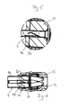
- Figure 1 is a longitudinal sectional view of one embodiment of pin contact in accordance with the invention, taken on the line A-A of Fig. 2,
- Figure 2 is a plan view of the pin contact shown in Fig. 1,
- Figure 3 is a perspective view of the pin contact of Figs. 1 and 2,
- Figure 4 is an axial cross section of an assembled co-axial connector incorporating the contact pin of Figs. 1 to 3, and
- Figure 5 is an enlarged fragmentary view showing a portion of the connector shown in Fig. 4.
-
- Referring to Figs. 1 to 3 of the drawings, a generally cylindrical contact pin is formed by rolling from sheet metal to the shape illustrated and is composed of suitable electrical contact material such as nickel plated brass or phosphor bronze.
- The dimensions of the pin correspond to those of a standard co-axial television cable connector and, typically, the pin would be of approximately 17.5mm in length and 2.4mm in external diameter. The
cylindrical wall 1 of the contact is tapered inwardly at oneend 2, in a conventional manner, and has alongitudinal slit 3 formed by the abutting edges of the rolled sheet from which the contact is formed. An opposite end of the contact has a trumpet shapedmouth 4 to facilitate insertion an electrical conductor and to retain the pin within an outer insulator as described below. - As can be seen from Figs. 1 and 3, an internally
angled spring finger 5 is formed by severing a portion of thecylindrical wall 1 of the contact pin and folding this inwardly to the shape illustrated. Thus, the internally directedspring finger 5 has a shoulder portion 6 forming a transition between thecylindrical wall 1 of the contact pin and a flattened portion 7 that is angled inwardly relatively to the axis of the contact pin, for example at an angle of approximately 155°. A flattened end portion 7A of thespring finger 5 is angled away from the longitudinal axis of the contact, at an angle of, for example, 25°, to form an elbow in thecontact finger 5 as shown in Fig. 1. The residual aperture left in the wall of the cylindrical contact terminates at a free edge in an outwardlyangled lip 8, as can be seen from Figs. 1 and 3. - Referring to Figs. 4 and 5, a complete electrical connector incorporating the contact of Figs. 1 and 3 comprises a generally
cylindrical metal sleeve 9 secured within a male screw threadedhousing member 10 and having aportion 9A of wider diameter and anarrow portion 9B. - An
annular member 11 of electrically insulating material is located within thesleeve 9 and has awider portion 11A fitting within thewider portion 9A of theconductor sleeve 9, and anarrow portion 11B fitting within thenarrow portion 9B of thesleeve 9. Theinsulator 11 is located axially by means of a shoulder of thesleeve 9 between the wider andnarrower portions - As illustrated more clearly in Fig. 5, the
contact pin 1 is a push fit within a central aperture of theannular insulator 11, thelip 8 of thecontact 1 serving as an abutment to snap engage with one end of theinsulator 11 and the widenedtrumpet mouth 4 abutting against the other end. Thecontact pin 1 is thus retained therein against relative displacement, in use. - As can also be seen from Fig. 5, the internal wall of the
insulator 11 overlies the aperture in the wall of thecontact pin 1, and thus presents the end 7A of thespring finger 5 from being displaced outwardly through the aperture in thewall 1 of the contact. Thus, upon insertion of a central wire conductor into the contact pin, the portion 7 of thespring finger 5 is firstly engaged by the wire conductor and displaced outwardly until the free end 7A contacts the internal surface of theinsulator 11. Thereafter, upon further insertion of the conductor wire, the two angled portions 7,7A of thefinger 5 are flexed relatively to one another in order to ensure firm contact between thespring finger 5 and the conductor wire. - After insertion of a central conductor of a coaxial cable into the contact pin, the cable is retained in place in conventional manner by securing a female threaded
cap 12 on to the male threadedhousing member 10, acollapsible contact member 13 providing an electrical connection between the outer conductor of the co-axial cable and thecylindrical sleeve 9 in a conventional manner that is well known to those skilled in the art. - Although the above described arrangement comprises one exemplary embodiment of the invention, it will be appreciated that various modifications and alternations may be made thereto without departing from the scope of the invention as defined in the appended Claims.
Claims (4)
- A pin contact for incorporation in an electrical cable connector, comprising a hollow generally cylindrical metal sleeve arranged to receive therein a wire conductor of an electrical cable, characterised in that a longitudincally extending portion of the wall (1) of the hollow pin is partially severed therefrom and angled inwardly (7) in order to define an inwardly extending spring finger (5) arranged to make pressure contact with a wire conductor inserted within the hollow pin.
- A pin contact according to Claim 1 wherein a free edge of an aperture defined in the wall (1) of said pin contact by the severance of said spring finger (5) is angled outwardly (8) to retain the pin contact within an annular insulator by snap engagement therein.
- A pin contact according to Claim 1 or 2, wherein the portion of said pin wall (1) defining said aperture is held within an annular insulator surrounding said pin contact, and said spring finger (5) has an end portion (7A) that is angled to define an elbow, the arrangement being such that upon insertion of a wire conductor within the hollow pin, said elbow portion is held in engagement therein by contact of said end portion (7A) against the internal wall of said annular insulator (11).
- A contact pin according to any one of Claims 1 to 3, wherein said pin contact is incorporated within a co-axial cable connector to form the centre pin thereof.
Priority Applications (3)
| Application Number | Priority Date | Filing Date | Title |
|---|---|---|---|
| EP01301442A EP1237226B1 (en) | 2001-02-19 | 2001-02-19 | Improvements in or relating to electrical connectors |
| AT01301442T ATE278254T1 (en) | 2001-02-19 | 2001-02-19 | IMPROVEMENTS IN OR RELATING TO ELECTRICAL CONNECTORS |
| DE60105965T DE60105965T2 (en) | 2001-02-19 | 2001-02-19 | Improvements in or regarding electrical connectors |
Applications Claiming Priority (1)
| Application Number | Priority Date | Filing Date | Title |
|---|---|---|---|
| EP01301442A EP1237226B1 (en) | 2001-02-19 | 2001-02-19 | Improvements in or relating to electrical connectors |
Publications (2)
| Publication Number | Publication Date |
|---|---|
| EP1237226A1 true EP1237226A1 (en) | 2002-09-04 |
| EP1237226B1 EP1237226B1 (en) | 2004-09-29 |
Family
ID=8181723
Family Applications (1)
| Application Number | Title | Priority Date | Filing Date |
|---|---|---|---|
| EP01301442A Expired - Lifetime EP1237226B1 (en) | 2001-02-19 | 2001-02-19 | Improvements in or relating to electrical connectors |
Country Status (3)
| Country | Link |
|---|---|
| EP (1) | EP1237226B1 (en) |
| AT (1) | ATE278254T1 (en) |
| DE (1) | DE60105965T2 (en) |
Cited By (3)
| Publication number | Priority date | Publication date | Assignee | Title |
|---|---|---|---|---|
| DE10317867B3 (en) * | 2003-04-17 | 2004-10-07 | Amphenol-Tuchel Electronics Gmbh | Contact arrangement for contacting electrical conductor has one-piece contact element with contact part for contacting matching counter contact and connector part for holding end of conductor |
| GB2423422A (en) * | 2004-02-21 | 2006-08-23 | Hitesh Dhanji Patel | Electrical connector preventing withdrawal of conductor |
| CN105870649A (en) * | 2016-05-25 | 2016-08-17 | 国网河南省电力公司济源供电公司 | Safe needle-like rapid connector |
Citations (3)
| Publication number | Priority date | Publication date | Assignee | Title |
|---|---|---|---|---|
| US5061207A (en) * | 1990-09-27 | 1991-10-29 | Gte Products Corporation | Connector for a shielded coaxial cable |
| US5474470A (en) * | 1994-03-30 | 1995-12-12 | Itt Corporation | Compensated interface coaxial connector apparatus |
| US5865654A (en) * | 1997-01-23 | 1999-02-02 | Raychem Corporation | Coaxial cable connector |
-
2001
- 2001-02-19 EP EP01301442A patent/EP1237226B1/en not_active Expired - Lifetime
- 2001-02-19 DE DE60105965T patent/DE60105965T2/en not_active Expired - Fee Related
- 2001-02-19 AT AT01301442T patent/ATE278254T1/en not_active IP Right Cessation
Patent Citations (3)
| Publication number | Priority date | Publication date | Assignee | Title |
|---|---|---|---|---|
| US5061207A (en) * | 1990-09-27 | 1991-10-29 | Gte Products Corporation | Connector for a shielded coaxial cable |
| US5474470A (en) * | 1994-03-30 | 1995-12-12 | Itt Corporation | Compensated interface coaxial connector apparatus |
| US5865654A (en) * | 1997-01-23 | 1999-02-02 | Raychem Corporation | Coaxial cable connector |
Cited By (4)
| Publication number | Priority date | Publication date | Assignee | Title |
|---|---|---|---|---|
| DE10317867B3 (en) * | 2003-04-17 | 2004-10-07 | Amphenol-Tuchel Electronics Gmbh | Contact arrangement for contacting electrical conductor has one-piece contact element with contact part for contacting matching counter contact and connector part for holding end of conductor |
| GB2423422A (en) * | 2004-02-21 | 2006-08-23 | Hitesh Dhanji Patel | Electrical connector preventing withdrawal of conductor |
| GB2423422B (en) * | 2004-02-21 | 2007-01-03 | Hitesh Dhanji Patel | Electrical connections and connectors |
| CN105870649A (en) * | 2016-05-25 | 2016-08-17 | 国网河南省电力公司济源供电公司 | Safe needle-like rapid connector |
Also Published As
| Publication number | Publication date |
|---|---|
| DE60105965D1 (en) | 2004-11-04 |
| DE60105965T2 (en) | 2005-10-13 |
| EP1237226B1 (en) | 2004-09-29 |
| ATE278254T1 (en) | 2004-10-15 |
Similar Documents
| Publication | Publication Date | Title |
|---|---|---|
| US4339166A (en) | Connector | |
| US7104826B2 (en) | Miniature BNC connector | |
| US4688876A (en) | Connector for coaxial cable | |
| US4619496A (en) | Coaxial plug and jack connectors | |
| US7070463B2 (en) | Waterproof relay connector | |
| US7455550B1 (en) | Snap-on coaxial plug | |
| EP0099633A1 (en) | Coaxial connector plug | |
| US5496968A (en) | Shielded cable connecting terminal | |
| US3047828A (en) | Connector | |
| EP0122700A2 (en) | Coaxial electrical connector for multiple outer conductor coaxial cable | |
| US4690481A (en) | Coaxial coupling | |
| EP1115177A3 (en) | Electrical plug connectors | |
| GB2079549A (en) | Coaxial cable connector | |
| EP0294419A1 (en) | Low profile press fit connector. | |
| US5536184A (en) | Connector assembly | |
| US5860833A (en) | Electrical connector having a probe positionable between a pair of spaced positions | |
| GB2139018A (en) | Coaxial plug and jack connectors | |
| US7001220B2 (en) | Coaxial plug-and-socket connection | |
| US4138188A (en) | Coaxial cable plug with center conductor as center contact | |
| US20030224658A1 (en) | Electrical connector | |
| US6955561B2 (en) | Inline connector | |
| EP1237226B1 (en) | Improvements in or relating to electrical connectors | |
| JP2019087517A (en) | Electrical connector | |
| US20020039853A1 (en) | Connector | |
| JP2006024499A (en) | Connector for coaxial cable |
Legal Events
| Date | Code | Title | Description |
|---|---|---|---|
| PUAI | Public reference made under article 153(3) epc to a published international application that has entered the european phase |
Free format text: ORIGINAL CODE: 0009012 |
|
| AK | Designated contracting states |
Kind code of ref document: A1 Designated state(s): AT BE CH CY DE DK ES FI FR GB GR IE IT LI LU MC NL PT SE TR |
|
| AX | Request for extension of the european patent |
Free format text: AL;LT;LV;MK;RO;SI |
|
| 17P | Request for examination filed |
Effective date: 20030304 |
|
| AKX | Designation fees paid |
Designated state(s): AT BE CH CY DE DK ES FI FR GB GR IE IT LI LU MC NL PT SE TR |
|
| 17Q | First examination report despatched |
Effective date: 20030724 |
|
| GRAP | Despatch of communication of intention to grant a patent |
Free format text: ORIGINAL CODE: EPIDOSNIGR1 |
|
| GRAS | Grant fee paid |
Free format text: ORIGINAL CODE: EPIDOSNIGR3 |
|
| GRAA | (expected) grant |
Free format text: ORIGINAL CODE: 0009210 |
|
| AK | Designated contracting states |
Kind code of ref document: B1 Designated state(s): AT BE CH CY DE DK ES FI FR GB GR IE IT LI LU MC NL PT SE TR |
|
| PG25 | Lapsed in a contracting state [announced via postgrant information from national office to epo] |
Ref country code: IT Free format text: LAPSE BECAUSE OF FAILURE TO SUBMIT A TRANSLATION OF THE DESCRIPTION OR TO PAY THE FEE WITHIN THE PRESCRIBED TIME-LIMIT;WARNING: LAPSES OF ITALIAN PATENTS WITH EFFECTIVE DATE BEFORE 2007 MAY HAVE OCCURRED AT ANY TIME BEFORE 2007. THE CORRECT EFFECTIVE DATE MAY BE DIFFERENT FROM THE ONE RECORDED. Effective date: 20040929 Ref country code: TR Free format text: LAPSE BECAUSE OF FAILURE TO SUBMIT A TRANSLATION OF THE DESCRIPTION OR TO PAY THE FEE WITHIN THE PRESCRIBED TIME-LIMIT Effective date: 20040929 Ref country code: AT Free format text: LAPSE BECAUSE OF FAILURE TO SUBMIT A TRANSLATION OF THE DESCRIPTION OR TO PAY THE FEE WITHIN THE PRESCRIBED TIME-LIMIT Effective date: 20040929 Ref country code: FI Free format text: LAPSE BECAUSE OF FAILURE TO SUBMIT A TRANSLATION OF THE DESCRIPTION OR TO PAY THE FEE WITHIN THE PRESCRIBED TIME-LIMIT Effective date: 20040929 Ref country code: LI Free format text: LAPSE BECAUSE OF FAILURE TO SUBMIT A TRANSLATION OF THE DESCRIPTION OR TO PAY THE FEE WITHIN THE PRESCRIBED TIME-LIMIT Effective date: 20040929 Ref country code: BE Free format text: LAPSE BECAUSE OF FAILURE TO SUBMIT A TRANSLATION OF THE DESCRIPTION OR TO PAY THE FEE WITHIN THE PRESCRIBED TIME-LIMIT Effective date: 20040929 Ref country code: CH Free format text: LAPSE BECAUSE OF FAILURE TO SUBMIT A TRANSLATION OF THE DESCRIPTION OR TO PAY THE FEE WITHIN THE PRESCRIBED TIME-LIMIT Effective date: 20040929 |
|
| REG | Reference to a national code |
Ref country code: GB Ref legal event code: FG4D |
|
| REG | Reference to a national code |
Ref country code: CH Ref legal event code: EP |
|
| REG | Reference to a national code |
Ref country code: IE Ref legal event code: FG4D |
|
| REF | Corresponds to: |
Ref document number: 60105965 Country of ref document: DE Date of ref document: 20041104 Kind code of ref document: P |
|
| PG25 | Lapsed in a contracting state [announced via postgrant information from national office to epo] |
Ref country code: SE Free format text: LAPSE BECAUSE OF FAILURE TO SUBMIT A TRANSLATION OF THE DESCRIPTION OR TO PAY THE FEE WITHIN THE PRESCRIBED TIME-LIMIT Effective date: 20041229 Ref country code: DK Free format text: LAPSE BECAUSE OF FAILURE TO SUBMIT A TRANSLATION OF THE DESCRIPTION OR TO PAY THE FEE WITHIN THE PRESCRIBED TIME-LIMIT Effective date: 20041229 Ref country code: GR Free format text: LAPSE BECAUSE OF FAILURE TO SUBMIT A TRANSLATION OF THE DESCRIPTION OR TO PAY THE FEE WITHIN THE PRESCRIBED TIME-LIMIT Effective date: 20041229 |
|
| PG25 | Lapsed in a contracting state [announced via postgrant information from national office to epo] |
Ref country code: ES Free format text: LAPSE BECAUSE OF FAILURE TO SUBMIT A TRANSLATION OF THE DESCRIPTION OR TO PAY THE FEE WITHIN THE PRESCRIBED TIME-LIMIT Effective date: 20050109 |
|
| PG25 | Lapsed in a contracting state [announced via postgrant information from national office to epo] |
Ref country code: CY Free format text: LAPSE BECAUSE OF FAILURE TO SUBMIT A TRANSLATION OF THE DESCRIPTION OR TO PAY THE FEE WITHIN THE PRESCRIBED TIME-LIMIT Effective date: 20050219 Ref country code: LU Free format text: LAPSE BECAUSE OF NON-PAYMENT OF DUE FEES Effective date: 20050219 |
|
| PG25 | Lapsed in a contracting state [announced via postgrant information from national office to epo] |
Ref country code: IE Free format text: LAPSE BECAUSE OF NON-PAYMENT OF DUE FEES Effective date: 20050221 |
|
| PG25 | Lapsed in a contracting state [announced via postgrant information from national office to epo] |
Ref country code: MC Free format text: LAPSE BECAUSE OF NON-PAYMENT OF DUE FEES Effective date: 20050228 |
|
| REG | Reference to a national code |
Ref country code: CH Ref legal event code: PL |
|
| PLBE | No opposition filed within time limit |
Free format text: ORIGINAL CODE: 0009261 |
|
| STAA | Information on the status of an ep patent application or granted ep patent |
Free format text: STATUS: NO OPPOSITION FILED WITHIN TIME LIMIT |
|
| PG25 | Lapsed in a contracting state [announced via postgrant information from national office to epo] |
Ref country code: DE Free format text: LAPSE BECAUSE OF NON-PAYMENT OF DUE FEES Effective date: 20050901 Ref country code: NL Free format text: LAPSE BECAUSE OF NON-PAYMENT OF DUE FEES Effective date: 20050901 |
|
| ET | Fr: translation filed | ||
| 26N | No opposition filed |
Effective date: 20050630 |
|
| NLV4 | Nl: lapsed or anulled due to non-payment of the annual fee |
Effective date: 20050901 |
|
| REG | Reference to a national code |
Ref country code: IE Ref legal event code: MM4A |
|
| PGFP | Annual fee paid to national office [announced via postgrant information from national office to epo] |
Ref country code: GB Payment date: 20060316 Year of fee payment: 6 |
|
| GBPC | Gb: european patent ceased through non-payment of renewal fee |
Effective date: 20070219 |
|
| PG25 | Lapsed in a contracting state [announced via postgrant information from national office to epo] |
Ref country code: PT Free format text: LAPSE BECAUSE OF NON-PAYMENT OF DUE FEES Effective date: 20050228 |
|
| PG25 | Lapsed in a contracting state [announced via postgrant information from national office to epo] |
Ref country code: GB Free format text: LAPSE BECAUSE OF NON-PAYMENT OF DUE FEES Effective date: 20070219 |
|
| PG25 | Lapsed in a contracting state [announced via postgrant information from national office to epo] |
Ref country code: FR Free format text: LAPSE BECAUSE OF NON-PAYMENT OF DUE FEES Effective date: 20050228 |
|
| REG | Reference to a national code |
Ref country code: FR Ref legal event code: ST Effective date: 20111021 |