EP1237159B1 - Open and close mechanism for recording medium insertion path - Google Patents
Open and close mechanism for recording medium insertion path Download PDFInfo
- Publication number
- EP1237159B1 EP1237159B1 EP02001277A EP02001277A EP1237159B1 EP 1237159 B1 EP1237159 B1 EP 1237159B1 EP 02001277 A EP02001277 A EP 02001277A EP 02001277 A EP02001277 A EP 02001277A EP 1237159 B1 EP1237159 B1 EP 1237159B1
- Authority
- EP
- European Patent Office
- Prior art keywords
- open
- recording medium
- insertion path
- door
- close
- Prior art date
- Legal status (The legal status is an assumption and is not a legal conclusion. Google has not performed a legal analysis and makes no representation as to the accuracy of the status listed.)
- Expired - Lifetime
Links
- 230000037431 insertion Effects 0.000 title claims description 110
- 238000003780 insertion Methods 0.000 title claims description 110
- 239000000428 dust Substances 0.000 description 1
- 239000002184 metal Substances 0.000 description 1
Images


Classifications
-
- G—PHYSICS
- G11—INFORMATION STORAGE
- G11B—INFORMATION STORAGE BASED ON RELATIVE MOVEMENT BETWEEN RECORD CARRIER AND TRANSDUCER
- G11B17/00—Guiding record carriers not specifically of filamentary or web form, or of supports therefor
- G11B17/02—Details
- G11B17/04—Feeding or guiding single record carrier to or from transducer unit
- G11B17/0401—Details
- G11B17/0405—Closing mechanism, e.g. door
Definitions
- the present invention relates to an open and close mechanism for a recording medium insertion path according to the independent claim 1 for inserting a recording medium into a mechanical body of an electric apparatus such as a record playback device.
- record playback devices such as a Compact Disk (CD is a short form used after this) player or a CD changer.
- CD Compact Disk
- the CD changer mentioned above, stores a plurality of CDs as recording medium and plays back recorded information on a selected CD by a car driver's request. And the playback information on the CD is outputted as a sound with a speaker of the car audio device.
- the CD player or the CD changer is provided with a recording medium insertion path, capable to put a plurality of CDs in and out.
- the recording medium path has a door capable to open and close for preventing dust coming into the CD changer inside.
- CD players or the CD changers have an open and close mechanism which inserts the CD into a mechanical body while the open and close door is opened by a car driver pushing with the CD.
- Fig. 10 - 13 conventional embodiments of CD players or CD changers are shown having an open and close mechanism 101 to open the recording medium insertion path for allowing inserting the CD only when a car driver operates a switch.
- the open and close mechanism 101 of the CD players or the CD changers which opens the recording medium insertion path 119 (shown in Fig. 12 and 13) only when the switch is operated, is provided with a door 113 capable to open and close the recording medium insertion path 119, a gear 115 and a driving member 107 mounted in the mechanical body, as shown in Fig. 10-13.
- the door 113 is formed into band shape and is bore capably to rotate about a center of an end portion 113a of a direction of width. The door rotates about the center of the end portion 113a so as to open and close the recording medium insertion path 119.
- the door 113 is integrally formed with a gear 121 on the end portion 113a, as shown in Fig. 10 and 11.
- the gear 115 is provided capably to rotate.
- the gear 115 meshes with the gear 121.
- the door 113 and the gear 115 are energized to a direction of closing the recording medium insertion path 119.
- the door 113 and the gear 115 close the recording medium insertion path 119 when a driving member 107 does not abut on the door, as shown in Fig. 10 and 12.
- the driving member 107 is provided in the mechanical body capably to slide for projecting from the mechanical body and receiving into the mechanical body inside.
- the driving member 107 abuts on the gear 115 when projecting from the mechanical body and rotates the gear 115 to a direction for opening the door 113 of the recording medium insertion path 119, as shown in Fig. 11 and 13.
- the driving member 107 moves to project from the mechanical body by operating the switch and rotates the gear 115 so that the door 113 opens the recording medium insertion path 119. After that, a car driver can put out the CD 103 received in the mechanical body or put the CD 103 into the mechanical body.
- the door 113 is energized only to a direction for closing the recording medium insertion path 119. Therefore, a richly experienced car driver in a CD changer to insert a CD 103 by pushing and opening the door 113 may insert the CD 103 into the mechanical body by forcing the door 113 open with the CD 103. Inserting a CD 103 into the mechanical body by forcing the door 113 open, the CD 103 may be inserted into the mechanical body in a disabled condition to receive a CD 103.
- the recording medium insertion path 119 is forced open by a car driver and a recording medium such as a CD 103 may be inserted by mistake, except in conditions of receiving and ejecting a CD 103.
- EP 0 307 917 A1 discloses a front door mechanism for signal recording-reproducing apparatus having a mechanical body, a recording medium insertion path, an open and close door being provided rotatably about a center of a pivot shaft for opening and closing the recording medium insertion path,
- an open and close mechanism for a recording medium insertion path for inserting a recording medium into a mechanical body of an electric apparatus such as a record playback device and ejecting the same therefrom, comprising a recording medium insertion path allowable to pass the recording medium therethrough; an open and close door being provided rotatably about a center of a pivot shaft extending along a direction of width of the recording medium insertion path and rotating about the center of said pivot shaft for opening and closing the recording medium insertion path; a shaft gear being disposed coaxially with the pivot shaft and rotating together with action of the open and close door; and a door gear being engaged with the shaft gear for rotating the open and close door, comprising an energizing device for energizing the door gear for causing the open and close door to close the recording medium insertion path; a driving device being installed in the mechanical body for operating said open and close door to open the recording medium insertion path by rotating the door gear; and a locking device for locking open and close operation
- the locking device locks an action for the open and close device opening the recording medium insertion path when the open and close device closes the recording medium insertion path. Then, inserting a recording medium into the mechanical body can be prevented when the open and close device closes the recording medium insertion path.
- lock by the locking device is released when the driving device works the open and close device to open the recording medium insertion path. Then, the recording medium insertion path can be opened securely when the driving device works the open and close device to open the recording medium insertion path.
- the locking device locks an action of the open and close device opening the recording medium insertion path. Therefore, inserting a recording medium into the mechanical body can be prevented when the open and close device closes the recording medium insertion path.
- the locking device allows the open and close door rotating when the driving device rotates the door gear. Therefore, the recording medium insertion path can be opened securely when the driving device works the open and close device to open the recording medium insertion path.
- the locking device locks the open and close door rotating on the center of the pivot shaft when the recording medium insertion path is closed. Therefore, except in a condition of the driving device working the open and close device to open the recording medium insertion path, the locking device locks an action of the open and close device path the recording medium insertion path. Then, inserting a recording medium into the mechanical body can be prevented when the open and close device closes the recording medium insertion path.
- the convex portion projecting from the cam member goes into the concave portion of the pivot shaft when the open and close door closes the recording medium insertion path.
- the pivot shaft rotating action is locked and the open and close door opening the recording medium insertion path is locked. Therefore, except in a condition of the driving device working the open and close device to open the recording medium insertion path, the locking device locks securely an action of the open and close device opening the recording medium insertion opening. Then, inserting a recording medium into the mechanical body can be prevented when the open and close device closes the recording medium insertion path.
- the cam member rotates together with the door gear when the door gear is rotated by mean of the driving device. And the convex portion goes through an inside of the concave portion to a direction for going out the concave portion. Therefore, the open and close door can rotate when the driving device rotates the door gear. Then, the recording medium insertion path can be opened securely when the driving device works the open and close device to open the recording medium insertion path.
- An open and close mechanism for a recording medium insertion path is installed in a CD changer 2 as a record playback device shown in Fig. 1.
- the CD changer 2 may be mounted on a car as a vehicle.
- the CD changer 2 receives a plurality of Compact Disks 3 (call CD after this) as recording medium and plays back the data recorded on the requested CD 3 according to order of a car driver in the car.
- the playback data are outputted as sounds with a speaker.
- the car driver can hear the recorded data on a requested CD 3 of a plurality of CDs 3 stored in the CD changer 2, by sounds.
- the CD changer 2 as shown in Fig. 1 and 2, includes a mechanical body 4, a front panel 5 mounted on the mechanical body 4 and the open and close mechanism 1 for a recording medium insertion path (call simply "open and close mechanism") according to an embodiment of this invention.
- the mechanical body 4 is provided with a casing 6, various functional parts mounted in the casing 6 and a recording medium containing portion 8 provided in the casing 6.
- the casing 6 is formed into box shape.
- the recording medium containing portion 8 contains a plurality of CDs 3, received in the casing 6 i.e. the mechanical body 4 through a later-described recording medium insertion path 19.
- the casing 6 is provided inside with a driving member 7 as a driving device for constituting the open and close mechanism 1.
- the driving member 7 is formed into band shape.
- the driving member 7, as shown in Fig. 2, is received in the casing 6 so as to make the length thereof along a direction for moving to or from the front panel 5.
- the driving member 7 is mounted in the casing 6 capably to move close to or away from the front panel 5.
- the driving member 7 slides by driving force such as a not-shown motor mounted in the casing 6 to move close to or away from the front panel 5.
- driving force such as a not-shown motor mounted in the casing 6 to move close to or away from the front panel 5.
- the driving member 7 abuts both an operating portion 22 of a later-described door gear 15 and an operating portion 29 of a locking cam 16 in the open and close mechanism 1.
- the driving member 7 moves both operating portions 22, 29 to a direction for pushing out from the equipment body 6 inside.
- the driving member 7 moves away from the both operating portions 22, 29 not to abut the both operating portions 22, 29.
- a direction for moving the driving member 7 away from the front panel 5 is defined as an inward direction toward the mechanical body 4 inside.
- a direction for the driving member 7 closing to the front panel 5 is defined as an outward direction toward the mechanical body 4 outside.
- the front panel 5 is mounted on a front side which is near side of the casing 6 i.e. the mechanical body 4 in Fig. 1.
- the front panel 5 is formed into a rectangular shape when viewed from top.
- the front panel 5 is provided with exposed switches 9, 10 for receiving a CD 3 into the mechanical body 4 and containing a CD 3 in the recording medium containing portion 8 or for ejecting a CD 3, contained in the recording medium containing portion 8, to out of the mechanical body 4.
- the front panel 5 is provided with a recording medium passing opening 11 communicating with a later-described recording medium insertion path 19 of the open and close mechanism 1.
- the recording medium passing opening 11 is formed going through the front panel 5 into a rectangular shape when viewed from top.
- the length of the recording medium passing opening 11 is along a direction of width of the CD changer 2.
- the recording medium passing opening 11 is formed with a height H1 along a direction of height of the CD changer 2 larger than a thickness of the CD 3 and with a width H2 along a direction of width of the CD changer 2 larger than a diameter of the CD 3.
- the recording medium passing opening 11 is almost same size or slightly larger size than the later-described recording medium insertion path 19 of the open and close mechanism 1.
- the front panel 5 forms an outer wall of the CD changer 2 i.e. a record playback device.
- the open and close mechanism 1 is mounted on the front panel 5.
- the open and close mechanism 1 is attached on an inner surface of the front panel 5 close to the casing 6.
- the open and close mechanism 1, as shown in Fig. 3-6, is provided with the above-mentioned driving member 7, a frame 12, an open and close door 13, a door gear 15, a first torsion spring 14 as an energizing device, a locking cam 16 as a cam member and a second torsion spring 36.
- the frame 12 is formed with a frame-shape frame body 17 and a second frame 18, as shown in Fig. 3 and 4.
- the frame body 17 is formed into frame-shape with beams 25, 26, 27 and 28.
- the beams 25, 26, 27 and 28 form marginal walls constituting the recording medium insertion path 19.
- An inner space enclosed with four beams 25, 26, 27 and 28 of the frame body 17 makes the recording medium insertion path 19.
- the recording medium insertion path 19 is formed into a rectangular shape when viewed from top.
- the length of the recording medium insertion path 19 is along a direction of width of the CD changer 2.
- the recording medium insertion path 19 is formed with a height H3 along a direction of height of the CD changer 2 larger than a thickness of the CD 3 and with a width H4 along a direction of width of the CD changer 2 larger than a diameter of the CD 3.
- the recording medium insertion path 19 is contiguous to the recording medium passing opening 11 when the open and close mechanism 1 is mounted on the front panel 5. Thus, the recording medium insertion path 19 is opened in the front panel 5.
- the recording medium insertion path 19 allows to insert a CD 3 into the mechanical body 4 inside.
- the recording medium passing opening 11 and the recording medium insertion path 19 constitutes a transporting path of a recording medium, described herein.
- the second frame 18 is mounted on the frame body 17.
- the second frame 18 may be made of sheet metal and is mounted on an end portion 17a of the frame body 17 along a direction of height of the CD changer 2. Both the door gear 15 and the locking cam 16 are placed between the second frame 18 and the frame body 17.
- the second frame 18 is provided with a hole 24 and a stopper piece 32.
- the stopper piece 32 is provided at rear walls side of the door gear 15 and the locking cam 16 when viewed from the front panel 5.
- An open and close door 13 is formed into band shape with almost same size or slightly smaller size than the recording medium insertion path 19.
- the open and close door 13 is held in the recording medium insertion path 19 so as to make the length thereof along a width direction of the CD changer 2 i.e. the recording medium insertion path 19.
- the open and close door 13 is provided with a couple of pivot shafts 20 projecting from both end portions of the length, as shown in Fig. 4-6.
- the respective pivot shaft 20 extends along a direction of width of the recording medium insertion path 19.
- the pivot shafts 20 are provided on the both end portions 13a in a direction of width of the open and close door 13 placed on one end portion in a direction of height of the recording medium insertion path 19.
- the end portions 13a are located at a top end of the open and close door 13 in a drawing of the embodiment.
- the end portions 13a form the end portion in a direction of height of the recording medium insertion path 19.
- the open and close door 13 is bore by the frame body 17, capably to rotate about a center of an pivot shafts 20. Therefore, the open and close door 13, rotated about the center of the end portion 13a in direction of width, located upper slide in drawings, opens or closes the recording medium insertion path 19.
- the pivot shaft 20, near the end portion 17a, is formed integrally with a gear 21 and a concave portion 31 (shown in Fig. 7).
- the gear 21 is disposed coaxially with the pivot shaft 20.
- the gear 21 is disposed coaxially with a rotation center of the pivot 20 i.e. a rotation center of the open and close door 13.
- the concave portion 31 is formed to be dent on the outer surface of the pivot shaft 20, as shown in Fig. 7.
- a open end 31c of the concave portion 31 corresponds to the locking cam 16 when the open and close door 13 closes the recording medium insertion path 19.
- the door gear 15 is formed into fan shape.
- the door gear 15 is bore by the second frame 18, capably to rotate about a center of a top portion 15a thereof (shown in Fig. 4).
- the door gear 15 meshes with the gear 21.
- the rotating door gear 15 rotates the open and close door 13 about the center of the pivot shafts 20 to make the open and close door 13 open or close the recording medium insertion path.
- the door gear 15 rotates interlocking with open and close action for the recording medium insertion path 19 by the open and close door 13.
- the door gear 15 is provided with the operating portion 22 moving away from the rotation center and projecting outwardly from an outer edge portion, and a stopper projection 23 located near the rotation center and projecting outwardly along a width direction of the CD changer 2.
- the operating portion 22 abuts on the driving member 7 moving toward the front panel 5 from the equipment body 6 inside of the mechanical body 4.
- the stopper projection 23 projects outwardly from the second frame 18 along a width direction of the CD changer 2 through the hole 24 when the door gear 15 is bore by the second frame 18 capably to rotate.
- the stopper projection 23, inserted through the hole 24, can control a rotation limit of the door gear 15 to be located between positions of the open and close door 13 opening and closing the recording medium insertion path 19.
- the door gear 15 abuts on the stopper piece 32 by energizing force of the first torsion spring 14 when the open and close door 13 close the recording medium insertion path 19.
- the open and close door 13, the door gear 15 and the first torsion spring 14 constitute the open and close device described above.
- the locking cam 16 is formed into fan shape.
- the locking cam 16 is bore by the second frame 18 capably to rotate about a center of the top portion 16a (shown in Fig. 4).
- the rotation center of the locking cam 16 is disposed coaxially with the rotation center of the door gear 15.
- the locking cam 16 is provided with the operating portion 29 moving away from the rotation center and projecting outwardly from an outer edge portion.
- the operating portion 29 abuts on the driving member 7 moving toward the front panel 5 from the equipment body 6 inside of the mechanical body 4.
- the locking cam 16 is energized by the second torsion spring 36 to position the operating portion 29 and the operating portion 22 of the door gear 15 in the same angle position and toward a direction for abutting on the stopper piece 32.
- the locking cam 16 is energized by energizing force of the second torsion spring 36 to position the operating portion 29 and the operating portion 22 of the door gear 15 in the same angle position and to abut on the stopper piece 32 when the open and close door 13 closes the recording medium insertion path 19. Therefore, the operating portion 29 of the locking cam 16 and the operating portion 22 of the door gear 15 abut almost simultaneously on the driving member 7 moving close to the front panel 5.
- the locking cam 16 is provided with a convex portion 30, as shown in Fig. 7.
- the convex portion 30 projects outwardly from an outer edge portion moving away from the rotation center of the locking cam 16.
- the convex portion 30, as shown in Fig. 7, goes into the concave portion 31 inside when the open and close door 13 closes the recording medium insertion path 19 and the locking cam 16 abuts on the stopper piece 32.
- a top end surface 30a of the convex portion 30 is positioned to be opposite to an edge portion 31a of the concave portion 31.
- the top end surface 30a of the convex portion 30 abuts on the edge portion 31a, at a near side of the mechanical body 4, of the concave portion 31. Then, the convex portion 30 and the concave portion 31 prevent the open and close door 13 rotating to a direction for opening the recording medium insertion path 19. Therefore, the convex portion 30, the concave portion 31 and the locking cam 16 prevent the open and close door 13 rotating about the center of the pivot shaft 20 by the convex portion 30 going into the concave portion 31 when the open and close door 13 closes the recording medium insertion path 19.
- the convex portion 30 is allowed to go out through the concave portion 31 inside from the edge portion 31b, at outer side of the mechanical body 4, of the concave portion 31. Therefore, the locking cam 16 rotates to a direction for getting the convex portion 30 out through the concave portion 31 from the edge portion 31b, when the locking cam 16 is pushed to a direction for moving the operating portion 29 close to the front panel 5.
- the convex portion 30 of the locking cam 16 allows the pivot shaft 20 rotating when the locking cam 16 rotates to a direction for moving the operating portion 29 close to the front panel 5. Therefore, the locking cam 16 is allowed to rotate to a direction for making the open and close door 13 open the recording medium insertion path 19 when the locking cam 16 rotates to a direction for moving the operating portion 29 close to the front panel 5.
- the convex portion 30 moves, interlocking with rotation of the door gear 15, in the concave portion 31 inside in a direction for going out from the concave portion 36 when the locking cam 16 rotating together with the door gear 15. Then, the convex portion 30, the concave portion 31 and the locking cam 16 allow the open and close door 13 rotating around the pivot shaft 20 when the locking cam 16 is rotated together with the door gear 15 by the driving member 7.
- the convex portion 30, the concave portion 31 and the locking cam 16 lock open and close action of the open and close door 13 when the open and close door 13 closes the recording medium insertion path 19.
- the convex portion 30 , the concave portion 31 and the locking cam 16 unlock the open and close door 13 when the driving member 7 makes the open and close door 13 open the recording medium insertion path 19.
- the convex portion 30, the concave portion 31 and the locking cam 16 allow the open and close door 13 rotating around the pivot shaft 20 when the driving member 7 rotates the door gear 15.
- the convex portion 30, the concave portion 31 and the locking cam 16 constitute the locking device described above.
- the driving member 7 is received in a rear room of the casing 6 of the mechanical body 4, moved away from the front panel 5, except in conditions of inserting a CD 3 into the mechanical body 4 or ejecting a CD 3 from the mechanical body 4.
- the driving member 7, as shown in Fig. 8, is away both from the operating portion 22 of the door gear 15 and the operating portion 29 of the locking cam 16.
- the open and close door 13 closes the recording medium insertion path 19 and the door gear 15 abuts on the stopper piece 32 by means of energizing force of the first torsion spring 14.
- the operating portion 29 of the locking cam 16 is positioned in the same angle position of the operating portion 22 of the door gear 15 and the locking cam 16 abuts on the stopper piece 32 by energizing force.
- the convex portion 30 is in the concave portion 31 inside.
- the driving member 7 moves slowly toward an outside of the mechanical body 4 when pushing the switch 9.
- the driving member 7 abuts both on the operating portions 22, 29.
- the driving member 7 pushes the operating portion 22 toward an outside of the mechanical body 4 in opposition to the energizing force by the first torsion spring 14.
- the driving member 7 pushes the operating portion 29 toward an outside of the front panel 5 i.e. the mechanical body 4 in opposition to the energizing force by the second torsion spring 36.
- the locking cam 16 rotates along an arrow K1 in Fig. 8 about the center of the top portion 16a and the convex portion 30 passes through the concave portion 31 inside toward the edge portion 31b close to the front panel 5.
- the door gear 15 rotates along an arrow K1 in Fig. 8 about the center of the top portion 15a and the open and close door 13 rotates along an arrow K2 in Fig. 8 about the center of the pivot shaft 20.
- the convex portion 30 is going out from the concave portion 31 and the open and close door 13 opens gradually the recording medium insertion path 19.
- a CD 3 is inserted through the recording medium insertion path 19 into the mechanical body 4 to be contained in the recording medium containing portion 8 and ejected through the recording medium insertion path 19 from the recording medium containing portion 8.
- the driving member 7 moves gradually toward the inside of the mechanical body 4 and the open and close door 13 closes the recording medium insertion path 19 by means of the energizing force of the torsion springs 14, 36 and the convex portion 30 goes into the concave portion 31 from the edge portion 31b.
- Fig. 8 and 9 the open and close door 13, the concave portion 31, the locking cam 16, the convex portion 30 and the driving member 7 are shown with solid line, and the gear 21 and the door gear 15 are shown with two-dot chain line, and the stopper piece 32 of the second frame 18 is shown with dotted line, and the beam 25 is shown with long dashed short dashed line.
- a CD 3 is shown with long dashed short dashed line.
- the convex portion 30 of the locking cam 16 is in the concave portion 31 formed on an outer surface of the pivot shaft 20 when the open and close door 13 closes the recording medium insertion path 19. Therefore, when trying to open the open and close door 13 along the arrow K2 in Fig. 7, the top end surface 30a of the convex portion 30 and an edge portion 31a abut on each other. Then, a force for opening is transmitted through the top end surface 30a to the edge portion 31a and received. Thus, rotating the pivot shaft 20 for opening the open and close door 13 is not allowed.
- the convex portion 30 and the concave portion 31 prevent to open the open and close door 13. Therefore, the recording medium insertion path 19 is kept closed except in a condition of the driving member 7 opening the open and close door 13.
- the open and close door 13 can not be opened, except in conditions of receiving a CD 3 into the CD changer 2 or ejecting a CD 3 from the CD changer 2. Therefore, in a disabled condition of the CD changer 2 receiving a CD 3, inserting a CD 3 into the mechanical body 4 is prevented. In short, miss-inserting a CD 3 can be prevented.
- the convex portion 30 is going out through the concave portion 31 inside.
- the locking cam 16 rotates about the center of the top portion 16a.
- the open and close door 13 opens the recording medium insertion path 19 securely. Also, when the CD changer 2 is in enabled conditions of inserting a CD 3 into the CD changer 2 and ejecting a CD 3 from the CD changer 2, inserting and ejecting a CD 3 can be done securely.
- the CD changer 2 is shown as a record playback device.
- the invention can be not only applied on the CD changer, but also other various record playback devices such as a CD player, a CD-ROM drive device for a navigation device.
Landscapes
- Feeding And Guiding Record Carriers (AREA)
- Casings For Electric Apparatus (AREA)
Description
- The present invention relates to an open and close mechanism for a recording medium insertion path according to the independent claim 1 for inserting a recording medium into a mechanical body of an electric apparatus such as a record playback device.
- In a car, there are installed various kind of car audio devices, record playback devices, such as a Compact Disk (CD is a short form used after this) player or a CD changer. The CD changer, mentioned above, stores a plurality of CDs as recording medium and plays back recorded information on a selected CD by a car driver's request. And the playback information on the CD is outputted as a sound with a speaker of the car audio device.
- The CD player or the CD changer is provided with a recording medium insertion path, capable to put a plurality of CDs in and out. The recording medium path has a door capable to open and close for preventing dust coming into the CD changer inside.
- Some of the CD players or the CD changers have an open and close mechanism which inserts the CD into a mechanical body while the open and close door is opened by a car driver pushing with the CD. In Fig. 10 - 13 conventional embodiments of CD players or CD changers are shown having an open and
close mechanism 101 to open the recording medium insertion path for allowing inserting the CD only when a car driver operates a switch. - The open and
close mechanism 101 of the CD players or the CD changers, which opens the recording medium insertion path 119 (shown in Fig. 12 and 13) only when the switch is operated, is provided with adoor 113 capable to open and close the recordingmedium insertion path 119, agear 115 and adriving member 107 mounted in the mechanical body, as shown in Fig. 10-13. - The
door 113 is formed into band shape and is bore capably to rotate about a center of anend portion 113a of a direction of width. The door rotates about the center of theend portion 113a so as to open and close the recordingmedium insertion path 119. Thedoor 113 is integrally formed with agear 121 on theend portion 113a, as shown in Fig. 10 and 11. - The
gear 115 is provided capably to rotate. Thegear 115 meshes with thegear 121. Thedoor 113 and thegear 115 are energized to a direction of closing the recordingmedium insertion path 119. Thedoor 113 and thegear 115 close the recordingmedium insertion path 119 when adriving member 107 does not abut on the door, as shown in Fig. 10 and 12. - The
driving member 107 is provided in the mechanical body capably to slide for projecting from the mechanical body and receiving into the mechanical body inside. Thedriving member 107 abuts on thegear 115 when projecting from the mechanical body and rotates thegear 115 to a direction for opening thedoor 113 of the recordingmedium insertion path 119, as shown in Fig. 11 and 13. - In the conventional open and
close mechanism 101, according to above-mentioned structure, thedriving member 107 moves to project from the mechanical body by operating the switch and rotates thegear 115 so that thedoor 113 opens the recordingmedium insertion path 119. After that, a car driver can put out theCD 103 received in the mechanical body or put theCD 103 into the mechanical body. - In the above-mentioned open and
close mechanism 101, thedoor 113 is energized only to a direction for closing the recordingmedium insertion path 119. Therefore, a richly experienced car driver in a CD changer to insert aCD 103 by pushing and opening thedoor 113 may insert theCD 103 into the mechanical body by forcing thedoor 113 open with theCD 103. Inserting aCD 103 into the mechanical body by forcing thedoor 113 open, theCD 103 may be inserted into the mechanical body in a disabled condition to receive aCD 103. - Thus, in the conventional open and
close mechanism 101, it is feared that the recordingmedium insertion path 119 is forced open by a car driver and a recording medium such as aCD 103 may be inserted by mistake, except in conditions of receiving and ejecting aCD 103. - Furthermore, EP 0 307 917 A1 discloses a front door mechanism for signal recording-reproducing apparatus having a mechanical body, a recording medium insertion path, an open and close door being provided rotatably about a center of a pivot shaft for opening and closing the recording medium insertion path,
- a gear,
- a door gear being engaged with said gear for rotating the open and close door,
- an energizing device for causing the open and close door to close the recording medium insertion path;
- a driving device being installed in the mechanical body for operating said gear, said door gear and thus said open and close door; and
- a locking device for locking the open and close door when the open and close door closes the recording medium insertion path,
- It is an objective of the present invention to provide an improved open and close mechanism for a recording medium insertion path which prevent the insertion of a recording medium into a mechanical body by mistake, except under circumstances where a recording playback device receives or ejects a recording medium.
- According to the present invention, the objective is solved by an open and close mechanism for a recording medium insertion path, for inserting a recording medium into a mechanical body of an electric apparatus such as a record playback device and ejecting the same therefrom, comprising a recording medium insertion path allowable to pass the recording medium therethrough; an open and close door being provided rotatably about a center of a pivot shaft extending along a direction of width of the recording medium insertion path and rotating about the center of said pivot shaft for opening and closing the recording medium insertion path; a shaft gear being disposed coaxially with the pivot shaft and rotating together with action of the open and close door; and a door gear being engaged with the shaft gear for rotating the open and close door, comprising an energizing device for energizing the door gear for causing the open and close door to close the recording medium insertion path; a driving device being installed in the mechanical body for operating said open and close door to open the recording medium insertion path by rotating the door gear; and a locking device for locking open and close operation of the open and close door when the open and close door closes the recording medium insertion path, wherein said locking device comprises a cam member rotatable about an axis coaxial with that of the door gear, and unlocks the open and close operation by rotating the cam member to allow the open and close door rotating about the center of the pivot shaft when the driving device rotates the door gear.
- Preferred embodiments of the present invention are laid down in the subclaims.
- Accordingly, the locking device locks an action for the open and close device opening the recording medium insertion path when the open and close device closes the recording medium insertion path. Then, inserting a recording medium into the mechanical body can be prevented when the open and close device closes the recording medium insertion path.
- Accordingly, lock by the locking device is released when the driving device works the open and close device to open the recording medium insertion path. Then, the recording medium insertion path can be opened securely when the driving device works the open and close device to open the recording medium insertion path.
- Except in a condition of the driving device working the open and close device to open the recording medium insertion path, the locking device locks an action of the open and close device opening the recording medium insertion path. Therefore, inserting a recording medium into the mechanical body can be prevented when the open and close device closes the recording medium insertion path.
- Accordingly, the locking device allows the open and close door rotating when the driving device rotates the door gear. Therefore, the recording medium insertion path can be opened securely when the driving device works the open and close device to open the recording medium insertion path.
- The locking device locks the open and close door rotating on the center of the pivot shaft when the recording medium insertion path is closed. Therefore, except in a condition of the driving device working the open and close device to open the recording medium insertion path, the locking device locks an action of the open and close device path the recording medium insertion path. Then, inserting a recording medium into the mechanical body can be prevented when the open and close device closes the recording medium insertion path.
- Accordingly, the convex portion projecting from the cam member goes into the concave portion of the pivot shaft when the open and close door closes the recording medium insertion path. Thereby, the pivot shaft rotating action is locked and the open and close door opening the recording medium insertion path is locked. Therefore, except in a condition of the driving device working the open and close device to open the recording medium insertion path, the locking device locks securely an action of the open and close device opening the recording medium insertion opening. Then, inserting a recording medium into the mechanical body can be prevented when the open and close device closes the recording medium insertion path.
- The cam member rotates together with the door gear when the door gear is rotated by mean of the driving device. And the convex portion goes through an inside of the concave portion to a direction for going out the concave portion. Therefore, the open and close door can rotate when the driving device rotates the door gear. Then, the recording medium insertion path can be opened securely when the driving device works the open and close device to open the recording medium insertion path.
- In the following, the present invention is explained in greater detail by means of several embodiments thereof in conjunction with the accompanying drawings, wherein:
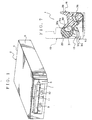
- Fig. 1 is a perspective view of a CD changer having an open and close mechanism for a recording medium insertion path of an embodiment according to the invention;
- Fig. 2 is a plan view, showing a layout of a driving member of a CD changer shown in Fig. 1;
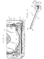
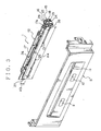
- Fig. 3 is a perspective view, showing a front panel and recording medium insertion path of a CD changer shown in Fig. 1;
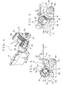
- Fig. 4 is an exploded perspective view of the open and close mechanism shown in Fig. 3;
- Fig. 5 is a perspective view, showing an open and close door and a door gear and locking cam assembled in the open and close mechanism shown in Fig. 3;
- Fig. 6 is a perspective view, showing an expanded VI area shown in Fig. 5;
- Fig. 7 is a sectional view taking along the line VII-VII line in Fig. 6;
- Fig. 8 is an explanatory drawing, showing a condition of a recording medium insertion path closed by an open and close door of an open and close mechanism according to an embodiment of the invention;
- Fig. 9 is an explanatory drawing, showing a condition of a recording medium insertion path opened by an open and close door of an open and close mechanism according to an embodiment of the invention;
- Fig. 10 is an explanatory drawing, showing a condition of closing an open and close door of a conventional open and close mechanism;
- Fig. 11 is an explanatory drawing, showing a condition of path an open and close door of an open and close mechanism shown in Fig. 10;
- Fig. 12 is a sectional view, showing a condition of closing an open and close door of an open and close mechanism shown in Fig. 10; and
- Fig. 13 is a sectional view, showing a condition of path an open and close door of an open and close mechanism shown in Fig. 10.
- An open and close mechanism for a recording medium insertion path according to an embodiment of this invention will now be described with reference to Fig. 1 - 9. An open and close mechanism 1 for a recording medium insertion path is installed in a
CD changer 2 as a record playback device shown in Fig. 1. TheCD changer 2 may be mounted on a car as a vehicle. - The
CD changer 2 receives a plurality of Compact Disks 3 (call CD after this) as recording medium and plays back the data recorded on the requestedCD 3 according to order of a car driver in the car. The playback data are outputted as sounds with a speaker. The car driver can hear the recorded data on a requestedCD 3 of a plurality ofCDs 3 stored in theCD changer 2, by sounds. - The
CD changer 2, as shown in Fig. 1 and 2, includes a mechanical body 4, afront panel 5 mounted on the mechanical body 4 and the open and close mechanism 1 for a recording medium insertion path (call simply "open and close mechanism") according to an embodiment of this invention. The mechanical body 4 is provided with acasing 6, various functional parts mounted in thecasing 6 and a recordingmedium containing portion 8 provided in thecasing 6. Thecasing 6 is formed into box shape. - Said functional parts are used for playing back data recorded on the
CD 3. The recordingmedium containing portion 8 contains a plurality ofCDs 3, received in thecasing 6 i.e. the mechanical body 4 through a later-described recordingmedium insertion path 19. - The
casing 6 is provided inside with a driving member 7 as a driving device for constituting the open and close mechanism 1. The driving member 7 is formed into band shape. The driving member 7, as shown in Fig. 2, is received in thecasing 6 so as to make the length thereof along a direction for moving to or from thefront panel 5. The driving member 7 is mounted in thecasing 6 capably to move close to or away from thefront panel 5. - The driving member 7 slides by driving force such as a not-shown motor mounted in the
casing 6 to move close to or away from thefront panel 5. When moving close to thefront panel 5, the driving member 7 abuts both an operatingportion 22 of a later-describeddoor gear 15 and an operatingportion 29 of a lockingcam 16 in the open and close mechanism 1. The driving member 7 moves both operatingportions equipment body 6 inside. When moving away from thefront panel 5, the driving member 7 moves away from the both operatingportions portions - Herein, a direction for moving the driving member 7 away from the
front panel 5 is defined as an inward direction toward the mechanical body 4 inside. A direction for the driving member 7 closing to thefront panel 5 is defined as an outward direction toward the mechanical body 4 outside. - The
front panel 5 is mounted on a front side which is near side of thecasing 6 i.e. the mechanical body 4 in Fig. 1. Thefront panel 5 is formed into a rectangular shape when viewed from top. Thefront panel 5 is provided with exposedswitches CD 3 into the mechanical body 4 and containing aCD 3 in the recordingmedium containing portion 8 or for ejecting aCD 3, contained in the recordingmedium containing portion 8, to out of the mechanical body 4. - The
front panel 5 is provided with a recordingmedium passing opening 11 communicating with a later-described recordingmedium insertion path 19 of the open and close mechanism 1. The recordingmedium passing opening 11 is formed going through thefront panel 5 into a rectangular shape when viewed from top. The length of the recordingmedium passing opening 11 is along a direction of width of theCD changer 2. - The recording
medium passing opening 11 is formed with a height H1 along a direction of height of theCD changer 2 larger than a thickness of theCD 3 and with a width H2 along a direction of width of theCD changer 2 larger than a diameter of theCD 3. The recordingmedium passing opening 11 is almost same size or slightly larger size than the later-described recordingmedium insertion path 19 of the open and close mechanism 1. - The
front panel 5, attached on theequipment body 6 of the mechanical body 4, constitutes an outer shell of theCD changer 2. Thefront panel 5 forms an outer wall of theCD changer 2 i.e. a record playback device. - The open and close mechanism 1 is mounted on the
front panel 5. The open and close mechanism 1 is attached on an inner surface of thefront panel 5 close to thecasing 6. The open and close mechanism 1, as shown in Fig. 3-6, is provided with the above-mentioned driving member 7, aframe 12, an open andclose door 13, adoor gear 15, afirst torsion spring 14 as an energizing device, a lockingcam 16 as a cam member and asecond torsion spring 36. - The
frame 12 is formed with a frame-shape frame body 17 and asecond frame 18, as shown in Fig. 3 and 4. Theframe body 17 is formed into frame-shape withbeams beams medium insertion path 19. An inner space enclosed with fourbeams frame body 17 makes the recordingmedium insertion path 19. - The recording
medium insertion path 19 is formed into a rectangular shape when viewed from top. The length of the recordingmedium insertion path 19 is along a direction of width of theCD changer 2. The recordingmedium insertion path 19 is formed with a height H3 along a direction of height of theCD changer 2 larger than a thickness of theCD 3 and with a width H4 along a direction of width of theCD changer 2 larger than a diameter of theCD 3. - The recording
medium insertion path 19 is contiguous to the recordingmedium passing opening 11 when the open and close mechanism 1 is mounted on thefront panel 5. Thus, the recordingmedium insertion path 19 is opened in thefront panel 5. The recordingmedium insertion path 19 allows to insert aCD 3 into the mechanical body 4 inside. The recordingmedium passing opening 11 and the recordingmedium insertion path 19 constitutes a transporting path of a recording medium, described herein. - The
second frame 18 is mounted on theframe body 17. Thesecond frame 18 may be made of sheet metal and is mounted on anend portion 17a of theframe body 17 along a direction of height of theCD changer 2. Both thedoor gear 15 and the lockingcam 16 are placed between thesecond frame 18 and theframe body 17. Thesecond frame 18 is provided with ahole 24 and astopper piece 32. Thestopper piece 32 is provided at rear walls side of thedoor gear 15 and the lockingcam 16 when viewed from thefront panel 5. - An open and
close door 13 is formed into band shape with almost same size or slightly smaller size than the recordingmedium insertion path 19. The open andclose door 13 is held in the recordingmedium insertion path 19 so as to make the length thereof along a width direction of theCD changer 2 i.e. the recordingmedium insertion path 19. The open andclose door 13 is provided with a couple ofpivot shafts 20 projecting from both end portions of the length, as shown in Fig. 4-6. - The
respective pivot shaft 20 extends along a direction of width of the recordingmedium insertion path 19. Thepivot shafts 20 are provided on the both end portions 13a in a direction of width of the open andclose door 13 placed on one end portion in a direction of height of the recordingmedium insertion path 19. The end portions 13a are located at a top end of the open andclose door 13 in a drawing of the embodiment. The end portions 13a form the end portion in a direction of height of the recordingmedium insertion path 19. - The open and
close door 13 is bore by theframe body 17, capably to rotate about a center of anpivot shafts 20. Therefore, the open andclose door 13, rotated about the center of the end portion 13a in direction of width, located upper slide in drawings, opens or closes the recordingmedium insertion path 19. - The
pivot shaft 20, near theend portion 17a, is formed integrally with agear 21 and a concave portion 31 (shown in Fig. 7). Thegear 21 is disposed coaxially with thepivot shaft 20. In other words, thegear 21 is disposed coaxially with a rotation center of thepivot 20 i.e. a rotation center of the open andclose door 13. - The
concave portion 31 is formed to be dent on the outer surface of thepivot shaft 20, as shown in Fig. 7. Aopen end 31c of theconcave portion 31 corresponds to the lockingcam 16 when the open andclose door 13 closes the recordingmedium insertion path 19. - The
door gear 15 is formed into fan shape. Thedoor gear 15 is bore by thesecond frame 18, capably to rotate about a center of atop portion 15a thereof (shown in Fig. 4). Thedoor gear 15 meshes with thegear 21. Therotating door gear 15 rotates the open andclose door 13 about the center of thepivot shafts 20 to make the open andclose door 13 open or close the recording medium insertion path. Thus, thedoor gear 15 rotates interlocking with open and close action for the recordingmedium insertion path 19 by the open andclose door 13. - The
door gear 15 is provided with the operatingportion 22 moving away from the rotation center and projecting outwardly from an outer edge portion, and astopper projection 23 located near the rotation center and projecting outwardly along a width direction of theCD changer 2. The operatingportion 22 abuts on the driving member 7 moving toward thefront panel 5 from theequipment body 6 inside of the mechanical body 4. - The
stopper projection 23 projects outwardly from thesecond frame 18 along a width direction of theCD changer 2 through thehole 24 when thedoor gear 15 is bore by thesecond frame 18 capably to rotate. Thestopper projection 23, inserted through thehole 24, can control a rotation limit of thedoor gear 15 to be located between positions of the open andclose door 13 opening and closing the recordingmedium insertion path 19. - The
first torsion spring 14, placed between thedoor gear 15 and thesecond frame 18, energizes thedoor gear 15 toward a direction for the open andclose door 13 closing the recordingmedium insertion path 19. Thedoor gear 15 abuts on thestopper piece 32 by energizing force of thefirst torsion spring 14 when the open andclose door 13 close the recordingmedium insertion path 19. Thedoor gear 15, rotated by the driving member 7 to a direction for the operatingportion 22 moving toward thefront panel 5, makes the open andclose door 13 open the recordingmedium insertion path 19. - The open and
close door 13, thedoor gear 15 and thefirst torsion spring 14 constitute the open and close device described above. - The locking
cam 16 is formed into fan shape. The lockingcam 16 is bore by thesecond frame 18 capably to rotate about a center of thetop portion 16a (shown in Fig. 4). The rotation center of the lockingcam 16 is disposed coaxially with the rotation center of thedoor gear 15. - The locking
cam 16 is provided with the operatingportion 29 moving away from the rotation center and projecting outwardly from an outer edge portion. The operatingportion 29 abuts on the driving member 7 moving toward thefront panel 5 from theequipment body 6 inside of the mechanical body 4. - The locking
cam 16 is energized by thesecond torsion spring 36 to position the operatingportion 29 and the operatingportion 22 of thedoor gear 15 in the same angle position and toward a direction for abutting on thestopper piece 32. The lockingcam 16 is energized by energizing force of thesecond torsion spring 36 to position the operatingportion 29 and the operatingportion 22 of thedoor gear 15 in the same angle position and to abut on thestopper piece 32 when the open andclose door 13 closes the recordingmedium insertion path 19. Therefore, the operatingportion 29 of the lockingcam 16 and the operatingportion 22 of thedoor gear 15 abut almost simultaneously on the driving member 7 moving close to thefront panel 5. - The locking
cam 16 is provided with aconvex portion 30, as shown in Fig. 7. Theconvex portion 30 projects outwardly from an outer edge portion moving away from the rotation center of the lockingcam 16. Theconvex portion 30, as shown in Fig. 7, goes into theconcave portion 31 inside when the open andclose door 13 closes the recordingmedium insertion path 19 and the lockingcam 16 abuts on thestopper piece 32. Simultaneously, atop end surface 30a of theconvex portion 30 is positioned to be opposite to anedge portion 31a of theconcave portion 31. - If the open and
close door 13 is tried to rotate about the center of thepivot shaft 20 toward a direction for opening the recordingmedium insertion path 19 in above condition, thetop end surface 30a of theconvex portion 30 abuts on theedge portion 31a, at a near side of the mechanical body 4, of theconcave portion 31. Then, theconvex portion 30 and theconcave portion 31 prevent the open andclose door 13 rotating to a direction for opening the recordingmedium insertion path 19. Therefore, theconvex portion 30, theconcave portion 31 and the lockingcam 16 prevent the open andclose door 13 rotating about the center of thepivot shaft 20 by theconvex portion 30 going into theconcave portion 31 when the open andclose door 13 closes the recordingmedium insertion path 19. - In Fig. 7, the open and
close door 13, theconcave portion 31, the lockingcam 16, theconvex portion 30 and thesecond torsion spring 36 are shown with a solid line and thesecond frame 18 is shown with a dotted line. - If the open and
close door 13 is tried to rotate to a direction for moving the operatingportion 29 close to the front panel, theconvex portion 30 is allowed to go out through theconcave portion 31 inside from theedge portion 31b, at outer side of the mechanical body 4, of theconcave portion 31. Therefore, the lockingcam 16 rotates to a direction for getting theconvex portion 30 out through theconcave portion 31 from theedge portion 31b, when the lockingcam 16 is pushed to a direction for moving the operatingportion 29 close to thefront panel 5. - The
convex portion 30 of the lockingcam 16 allows thepivot shaft 20 rotating when the lockingcam 16 rotates to a direction for moving the operatingportion 29 close to thefront panel 5. Therefore, the lockingcam 16 is allowed to rotate to a direction for making the open andclose door 13 open the recordingmedium insertion path 19 when the lockingcam 16 rotates to a direction for moving the operatingportion 29 close to thefront panel 5. - In other words, the
convex portion 30 moves, interlocking with rotation of thedoor gear 15, in theconcave portion 31 inside in a direction for going out from theconcave portion 36 when the lockingcam 16 rotating together with thedoor gear 15. Then, theconvex portion 30, theconcave portion 31 and the lockingcam 16 allow the open andclose door 13 rotating around thepivot shaft 20 when the lockingcam 16 is rotated together with thedoor gear 15 by the driving member 7. - Thus, the
convex portion 30, theconcave portion 31 and the lockingcam 16 lock open and close action of the open andclose door 13 when the open andclose door 13 closes the recordingmedium insertion path 19. And theconvex portion 30 , theconcave portion 31 and the lockingcam 16 unlock the open andclose door 13 when the driving member 7 makes the open andclose door 13 open the recordingmedium insertion path 19. Theconvex portion 30, theconcave portion 31 and the lockingcam 16 allow the open andclose door 13 rotating around thepivot shaft 20 when the driving member 7 rotates thedoor gear 15. - The
convex portion 30, theconcave portion 31 and the lockingcam 16 constitute the locking device described above. - The open and close mechanism 1, with above-mentioned structure, which is mounted on the
front panel 5 assembled in thecasing 6 of the mechanical body 4, constitutes a part of theCD changer 2. In theCD changer 2, the driving member 7 is received in a rear room of thecasing 6 of the mechanical body 4, moved away from thefront panel 5, except in conditions of inserting aCD 3 into the mechanical body 4 or ejecting aCD 3 from the mechanical body 4. - The driving member 7, as shown in Fig. 8, is away both from the operating
portion 22 of thedoor gear 15 and the operatingportion 29 of the lockingcam 16. The open andclose door 13 closes the recordingmedium insertion path 19 and thedoor gear 15 abuts on thestopper piece 32 by means of energizing force of thefirst torsion spring 14. - The operating
portion 29 of the lockingcam 16 is positioned in the same angle position of the operatingportion 22 of thedoor gear 15 and the lockingcam 16 abuts on thestopper piece 32 by energizing force. Theconvex portion 30 is in theconcave portion 31 inside. - Thereafter, the driving member 7 moves slowly toward an outside of the mechanical body 4 when pushing the
switch 9. The driving member 7 abuts both on the operatingportions portion 22 toward an outside of the mechanical body 4 in opposition to the energizing force by thefirst torsion spring 14. The driving member 7 pushes the operatingportion 29 toward an outside of thefront panel 5 i.e. the mechanical body 4 in opposition to the energizing force by thesecond torsion spring 36. - Then, the locking
cam 16 rotates along an arrow K1 in Fig. 8 about the center of thetop portion 16a and theconvex portion 30 passes through theconcave portion 31 inside toward theedge portion 31b close to thefront panel 5. And thedoor gear 15 rotates along an arrow K1 in Fig. 8 about the center of thetop portion 15a and the open andclose door 13 rotates along an arrow K2 in Fig. 8 about the center of thepivot shaft 20. Theconvex portion 30 is going out from theconcave portion 31 and the open andclose door 13 opens gradually the recordingmedium insertion path 19. - When the driving member 7, as shown in Fig. 9, moves more toward the outside of the mechanical body 4, the
convex portion 30 passes near theedge portion 31b and goes out from theconcave portion 31. Then, the open andclose door 13 opens the recordingmedium insertion path 19. Thus, the open andclose door 13 opens the recordingmedium insertion path 19. - A
CD 3 is inserted through the recordingmedium insertion path 19 into the mechanical body 4 to be contained in the recordingmedium containing portion 8 and ejected through the recordingmedium insertion path 19 from the recordingmedium containing portion 8. When pushing theswitch 10, the driving member 7 moves gradually toward the inside of the mechanical body 4 and the open andclose door 13 closes the recordingmedium insertion path 19 by means of the energizing force of the torsion springs 14, 36 and theconvex portion 30 goes into theconcave portion 31 from theedge portion 31b. - In Fig. 8 and 9, the open and
close door 13, theconcave portion 31, the lockingcam 16, theconvex portion 30 and the driving member 7 are shown with solid line, and thegear 21 and thedoor gear 15 are shown with two-dot chain line, and thestopper piece 32 of thesecond frame 18 is shown with dotted line, and thebeam 25 is shown with long dashed short dashed line. In Fig. 9, aCD 3 is shown with long dashed short dashed line. - According to this embodiment of the invention, the
convex portion 30 of the lockingcam 16 is in theconcave portion 31 formed on an outer surface of thepivot shaft 20 when the open andclose door 13 closes the recordingmedium insertion path 19. Therefore, when trying to open the open andclose door 13 along the arrow K2 in Fig. 7, thetop end surface 30a of theconvex portion 30 and anedge portion 31a abut on each other. Then, a force for opening is transmitted through thetop end surface 30a to theedge portion 31a and received. Thus, rotating thepivot shaft 20 for opening the open andclose door 13 is not allowed. - Thus, when the open and
close door 13 closes the recordingmedium insertion path 19, theconvex portion 30 and theconcave portion 31 prevent to open the open andclose door 13. Therefore, the recordingmedium insertion path 19 is kept closed except in a condition of the driving member 7 opening the open andclose door 13. - Then, the open and
close door 13 can not be opened, except in conditions of receiving aCD 3 into theCD changer 2 or ejecting aCD 3 from theCD changer 2. Therefore, in a disabled condition of theCD changer 2 receiving aCD 3, inserting aCD 3 into the mechanical body 4 is prevented. In short, miss-inserting aCD 3 can be prevented. - Furthermore, when the driving member 7 moves toward an outside of the mechanical body 4 and pushes the operating
portions convex portion 30 is going out through theconcave portion 31 inside. The lockingcam 16 rotates about the center of thetop portion 16a. Thus, when the driving member 7 moves toward an outside of the mechanical body 4 and pushes the operatingportions close door 13 rotates about the center of thepivot i shaft 20 and opens the recordingmedium insertion path 19. - Thus, when the
CD changer 2 is in enabled conditions of inserting aCD 3 into theCD changer 2 and ejecting aCD 3 from theCD changer 2 by the driving member 7 moving toward an outside of the mechanical body 4, the open andclose door 13 opens the recordingmedium insertion path 19 securely. Also, when theCD changer 2 is in enabled conditions of inserting aCD 3 into theCD changer 2 and ejecting aCD 3 from theCD changer 2, inserting and ejecting aCD 3 can be done securely. - In the embodiment of the invention mentioned above, the
CD changer 2 is shown as a record playback device. The invention can be not only applied on the CD changer, but also other various record playback devices such as a CD player, a CD-ROM drive device for a navigation device.
Claims (2)
- An opening and closing mechanism for permitting the insertion of a recording medium into a mechanical body (4) of an electric apparatus such as a record playback device (2) and permitting the ejection of the same therefrom, comprising:a recording medium insertion path (19) arranged to pass the recording medium therethrough;an open and close door (13) being provided rotatably about a center of a pivot shaft (20) extending along a direction of width of the recording medium insertion path (19) and rotating about the center of said pivot shaft (20) for opening and closing the recording medium insertion path (19);a shaft gear (21) being disposed coaxially with the pivot shaft (20) and rotating together with the open and close door (13); anda door gear (15) being engaged with the shaft gear (21) for rotating the open and close door (13),an energizing device (14) for energizing the door gear (15) for causing the open and close door (13) to close the recording medium insertion path (19);a driving device (7) being installed in the mechanical body (4) for operating said open and close door (13) to open the recording medium insertion path (19) by rotating the door gear (15); anda locking device for locking the open and close door (13) when the open and close door (13) closes the recording medium insertion path (19), wherein said locking device comprises a cam member (16) rotatable about an axis coaxial with that of the door gear (15), and said locking device unlocks the open and close door (6) by rotating the cam member (16) to allow the open and close door (13) rotating about the center of the pivot shaft (20) when the driving device (7) rotates the door gear (15).
- An open and close mechanism for a recording medium insertion path according to claim 1, wherein said locking device comprises:a convex portion (30) projecting toward the pivot shaft (20) from the cam member (16); anda concave portion (31) formed concavely on an outer surface of the pivot shaft (20), wherein the convex portion (30) goes into the concave portion (31) to lock the open and close door (13) rotating about the center of the pivot shaft (20) when the open and close door (13) closing the recording medium insertion path (19), wherein the cam member (16) rotates to move the convex portion (30) in and out of the concave portion (31) to allow the open and close door (13) rotating about the center of the pivot shaft (20) when the cam member (16) is rotated together with the door gear (15) by the driving device (7).
Applications Claiming Priority (2)
| Application Number | Priority Date | Filing Date | Title |
|---|---|---|---|
| JP2001055160 | 2001-02-28 | ||
| JP2001055160A JP2002260319A (en) | 2001-02-28 | 2001-02-28 | Opening/closing device of recording medium loading slot |
Publications (3)
| Publication Number | Publication Date |
|---|---|
| EP1237159A2 EP1237159A2 (en) | 2002-09-04 |
| EP1237159A3 EP1237159A3 (en) | 2003-11-26 |
| EP1237159B1 true EP1237159B1 (en) | 2007-04-04 |
Family
ID=18915382
Family Applications (1)
| Application Number | Title | Priority Date | Filing Date |
|---|---|---|---|
| EP02001277A Expired - Lifetime EP1237159B1 (en) | 2001-02-28 | 2002-01-17 | Open and close mechanism for recording medium insertion path |
Country Status (4)
| Country | Link |
|---|---|
| US (1) | US6931649B2 (en) |
| EP (1) | EP1237159B1 (en) |
| JP (1) | JP2002260319A (en) |
| DE (1) | DE60219230T2 (en) |
Families Citing this family (5)
| Publication number | Priority date | Publication date | Assignee | Title |
|---|---|---|---|---|
| US6969964B2 (en) * | 2004-01-26 | 2005-11-29 | Hewlett-Packard Development Company, L.P. | Control device and method of use |
| TWM255988U (en) * | 2004-02-27 | 2005-01-21 | Lite On It Corp | A broken-disc ejected protector used in a slot-in optical recording and/or reproducing apparatus |
| US7827568B1 (en) * | 2004-03-10 | 2010-11-02 | Apple Inc. | Integration of structural and cosmetic bezel having a disk guide for a slot loading optical drive |
| US20060291154A1 (en) * | 2005-06-23 | 2006-12-28 | Apple Computer, Inc. | Guard system for portable computer disk drive slot |
| US8615929B2 (en) * | 2010-07-20 | 2013-12-31 | Scd | Door opening/closing device for ice dispenser in refrigerator |
Family Cites Families (20)
| Publication number | Priority date | Publication date | Assignee | Title |
|---|---|---|---|---|
| US1288665A (en) * | 1918-03-28 | 1918-12-24 | Herbert Page | Sliding door or flap for bookcases, cabinets, and like furniture. |
| US3794401A (en) * | 1971-10-20 | 1974-02-26 | Wright Barry Corp | Door guide |
| JPS6064441U (en) * | 1983-10-05 | 1985-05-07 | 日本ビクター株式会社 | Tape storage case insertion lid lock mechanism |
| JPS61236089A (en) * | 1985-04-10 | 1986-10-21 | Mitsubishi Electric Corp | Door opening/closing mechanism |
| JPH0834056B2 (en) * | 1987-02-13 | 1996-03-29 | アルプス電気株式会社 | Door device |
| EP0307917B1 (en) * | 1987-09-17 | 1992-02-19 | Sanyo Electric Co., Ltd. | Front door mechanism for signal recording-reproducing apparatus for use with cassette |
| US5301178A (en) * | 1990-02-22 | 1994-04-05 | Olypus Optical Co., Ltd. | Drive unit for optical memory device with portion of drive means mounted outside a sealing means |
| JPH03286457A (en) * | 1990-03-31 | 1991-12-17 | Toshiba Corp | Cassette loading device |
| JP3276986B2 (en) * | 1992-06-29 | 2002-04-22 | 日本電産コパル株式会社 | Open / close door mechanism |
| US5537378A (en) * | 1993-08-25 | 1996-07-16 | Clarion Co., Ltd. | Data processing device with controlled insertion of recording media |
| US5383072A (en) * | 1993-08-25 | 1995-01-17 | Samsung Electronics Co., Ltd. | Door lock apparatus for use in a tape recorder |
| US5481520A (en) * | 1994-01-06 | 1996-01-02 | Shinano Kenshi Kabushiki Kaisha | Disk player door assembly |
| KR0170305B1 (en) * | 1995-11-08 | 1999-04-15 | 김광호 | Front Door Lock on Tape Recorder |
| US5689490A (en) * | 1996-02-06 | 1997-11-18 | Sony Corporation | MO cartridge jukebox doors which open in a plane parallel to the front panel of the jukebox |
| JPH09297983A (en) * | 1996-05-02 | 1997-11-18 | Alps Electric Co Ltd | Door opening and closing mechanism for recording and reproducing device |
| JPH11126401A (en) * | 1997-10-20 | 1999-05-11 | Sony Corp | Recording and playback device |
| JP4055288B2 (en) * | 1999-03-19 | 2008-03-05 | ソニー株式会社 | Disk unit |
| JP3701500B2 (en) * | 1999-04-08 | 2005-09-28 | パイオニア株式会社 | Door opener |
| JP2001101736A (en) * | 1999-09-30 | 2001-04-13 | Sony Corp | Recording and playback device |
| US6618339B2 (en) * | 2001-02-28 | 2003-09-09 | Pioneer Corporation | Closure assembly for record medium entry passage |
-
2001
- 2001-02-28 JP JP2001055160A patent/JP2002260319A/en active Pending
-
2002
- 2002-01-17 EP EP02001277A patent/EP1237159B1/en not_active Expired - Lifetime
- 2002-01-17 DE DE60219230T patent/DE60219230T2/en not_active Expired - Fee Related
- 2002-02-12 US US10/072,915 patent/US6931649B2/en not_active Expired - Fee Related
Also Published As
| Publication number | Publication date |
|---|---|
| DE60219230T2 (en) | 2007-07-19 |
| EP1237159A3 (en) | 2003-11-26 |
| DE60219230D1 (en) | 2007-05-16 |
| JP2002260319A (en) | 2002-09-13 |
| EP1237159A2 (en) | 2002-09-04 |
| US6931649B2 (en) | 2005-08-16 |
| US20020118626A1 (en) | 2002-08-29 |
Similar Documents
| Publication | Publication Date | Title |
|---|---|---|
| JP3276986B2 (en) | Open / close door mechanism | |
| EP0174651B1 (en) | Disc cartridge | |
| EP1237159B1 (en) | Open and close mechanism for recording medium insertion path | |
| US5481520A (en) | Disk player door assembly | |
| EP0936613B1 (en) | Cartridge for accommodating a disc | |
| JP2000030399A (en) | Disk cartridge | |
| US6618339B2 (en) | Closure assembly for record medium entry passage | |
| JP2003016768A (en) | Structure for preventing erroneous insertion of information recording medium | |
| JP2000156061A (en) | Disk cartridge | |
| JP2000030397A (en) | Disk cartridge | |
| JP3424637B2 (en) | Disc player for both mini and compact discs | |
| JP2643750B2 (en) | Optical disk cartridge | |
| JP4348694B2 (en) | Electronic device with open / close lid | |
| JP3395947B2 (en) | Disc player for both mini and compact discs | |
| JP2003100067A (en) | Disk shutter device | |
| JP3473618B2 (en) | Disc player for both mini and compact discs | |
| JP3473617B2 (en) | Disc player for both mini and compact discs | |
| JP2002260318A (en) | Opening/closing device of recording medium transporting route | |
| JPH11250642A (en) | Disc loading opening structure of disc reproducing device | |
| JP2765503B2 (en) | Disk unit | |
| JP3420822B2 (en) | Disk unit | |
| JP2001184768A (en) | Disk exchanger | |
| JPH0419625Y2 (en) | ||
| JP3807378B2 (en) | Mini-disc and compact disc player | |
| JP2002260317A (en) | Opening/closing device of recording medium transporting route |
Legal Events
| Date | Code | Title | Description |
|---|---|---|---|
| PUAI | Public reference made under article 153(3) epc to a published international application that has entered the european phase |
Free format text: ORIGINAL CODE: 0009012 |
|
| AK | Designated contracting states |
Kind code of ref document: A2 Designated state(s): AT BE CH CY DE DK ES FI FR GB GR IE IT LI LU MC NL PT SE TR |
|
| AX | Request for extension of the european patent |
Free format text: AL;LT;LV;MK;RO;SI |
|
| PUAL | Search report despatched |
Free format text: ORIGINAL CODE: 0009013 |
|
| AK | Designated contracting states |
Kind code of ref document: A3 Designated state(s): AT BE CH CY DE DK ES FI FR GB GR IE IT LI LU MC NL PT SE TR |
|
| AX | Request for extension of the european patent |
Extension state: AL LT LV MK RO SI |
|
| 17P | Request for examination filed |
Effective date: 20040116 |
|
| AKX | Designation fees paid |
Designated state(s): DE FR GB |
|
| 17Q | First examination report despatched |
Effective date: 20040805 |
|
| GRAP | Despatch of communication of intention to grant a patent |
Free format text: ORIGINAL CODE: EPIDOSNIGR1 |
|
| GRAS | Grant fee paid |
Free format text: ORIGINAL CODE: EPIDOSNIGR3 |
|
| GRAA | (expected) grant |
Free format text: ORIGINAL CODE: 0009210 |
|
| AK | Designated contracting states |
Kind code of ref document: B1 Designated state(s): DE FR GB |
|
| REG | Reference to a national code |
Ref country code: GB Ref legal event code: FG4D |
|
| REF | Corresponds to: |
Ref document number: 60219230 Country of ref document: DE Date of ref document: 20070516 Kind code of ref document: P |
|
| ET | Fr: translation filed | ||
| PLBE | No opposition filed within time limit |
Free format text: ORIGINAL CODE: 0009261 |
|
| STAA | Information on the status of an ep patent application or granted ep patent |
Free format text: STATUS: NO OPPOSITION FILED WITHIN TIME LIMIT |
|
| 26N | No opposition filed |
Effective date: 20080107 |
|
| GBPC | Gb: european patent ceased through non-payment of renewal fee |
Effective date: 20080117 |
|
| PG25 | Lapsed in a contracting state [announced via postgrant information from national office to epo] |
Ref country code: DE Free format text: LAPSE BECAUSE OF NON-PAYMENT OF DUE FEES Effective date: 20080801 |
|
| REG | Reference to a national code |
Ref country code: FR Ref legal event code: ST Effective date: 20081029 |
|
| PG25 | Lapsed in a contracting state [announced via postgrant information from national office to epo] |
Ref country code: GB Free format text: LAPSE BECAUSE OF NON-PAYMENT OF DUE FEES Effective date: 20080117 |
|
| PG25 | Lapsed in a contracting state [announced via postgrant information from national office to epo] |
Ref country code: FR Free format text: LAPSE BECAUSE OF NON-PAYMENT OF DUE FEES Effective date: 20080131 |