EP1237115A2 - Automatic table location in documents - Google Patents
Automatic table location in documents Download PDFInfo
- Publication number
- EP1237115A2 EP1237115A2 EP02075780A EP02075780A EP1237115A2 EP 1237115 A2 EP1237115 A2 EP 1237115A2 EP 02075780 A EP02075780 A EP 02075780A EP 02075780 A EP02075780 A EP 02075780A EP 1237115 A2 EP1237115 A2 EP 1237115A2
- Authority
- EP
- European Patent Office
- Prior art keywords
- lines
- document
- crop
- location
- crops
- Prior art date
- Legal status (The legal status is an assumption and is not a legal conclusion. Google has not performed a legal analysis and makes no representation as to the accuracy of the status listed.)
- Granted
Links
Images


Classifications
-
- G—PHYSICS
- G06—COMPUTING OR CALCULATING; COUNTING
- G06V—IMAGE OR VIDEO RECOGNITION OR UNDERSTANDING
- G06V30/00—Character recognition; Recognising digital ink; Document-oriented image-based pattern recognition
- G06V30/40—Document-oriented image-based pattern recognition
- G06V30/41—Analysis of document content
- G06V30/412—Layout analysis of documents structured with printed lines or input boxes, e.g. business forms or tables
Definitions
- the present invention relates to the automatic locating of table-like structures present in documents.
- table-like structures may be, for example, the whole or parts of tables present on forms (a "table", here, being a two-dimensional assembly of cells).
- a "table" here, being a two-dimensional assembly of cells.
- the present invention is of particular interest with regard to the automatic locating of title blocks (or “legends") in technical drawings.
- the term "table” is used to designate all of the aforementioned examples, and table-like structures in general.
- the techniques of the present invention will usually, but not exclusively, be applied to representations of documents, such as scanned images of documents, vector representations of the images present on documents, etc.
- the legend is a table-like form, composed of various rectangular cells, or "fields", located within the page.
- the cells contain information and three fields are compulsory:
- the identification portion of the title block "shall be at the right-hand bottom corner of the title block when seen in its normal direction of viewing, and have a maximum length of 170 mm".
- the dimensions of the title block shall not exceed 190 mm in width and 277 mm in height.
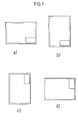
- ISO 5457 also specifies that "the position of the title block should be within the drawing space such that the portion of the title block containing the identification of the drawing (registration number, title, origin, etc.) is situated in the bottom right-hand corner of the drawing space, both for sheets positioned horizontally, type X (see Fig.1a)), or vertically, type Y (see Fig.1b)).
- the direction of viewing of the title block should correspond in general to that of the drawing. Nevertheless, in order to economise on preprinted drawing sheets, it is permitted to use sheets type X in the vertical position (see Fig.1c)) and sheets type Y in the horizontal position (see Fig.1d)). In these cases, the identification portion of the title block should be in the right-hand top corner of the drawing space, and orientated such that the title block may be read when viewed from the right.”
- title block location generally is performed based on scanned images of technical drawings and the above-mentioned features may be absent from the scanned image due to bad positioning of the drawing during scanning. Thus, title block location should be based upon other factors.
- the present invention seeks to overcome the problems and disadvantages inherent in the prior art methods of table location. More particularly, preferred embodiments of the present invention provide robust table-location methods and apparatus in which specific tables present on a document can be located reliably and quickly.
- the techniques of the present invention involve the analysis of sub-regions of the document, these sub-regions being termed "crops" of the document.
- the present invention provides a method automatically locating tables in documents, the method comprising the steps of:
- the detected image lines correspond to the lines making up the image and not pixels of the background colour of the medium on which the image is presented.
- the length of the detected lines may be determined in any convenient way. For example, in the case where the processed document is scanned and it is the scanned image that is analysed, it can be convenient to count the numbers of image pixels present on the different scan lines. As another example, in the case where an image of the document is analysed under an HPGL (Hewlett-Packard Graphics Language) representation, the data is in vector format and the vector information includes data on the length of the lines making up the image.
- the length of a detected line may be represented in any convenient way, for example, in terms of the numbers of image pixels making up the line, in terms of conventional units of measurement (centimetres, millimetres), etc.
- the evaluated parameter indicative of density of detected lines may be the number of detected lines within groups defined for each crop, lines being assigned to a common group if the separation between adjacent pairs of these lines is less than a reference value.
- the decision process may also include consideration of the thickness of the detected lines in the different crops.
- the method according to the present invention is based on signal measurements from the whole document. Moreover, it involves evaluation of a relatively small number of parameters, each of which has a physical meaning. Accordingly it is robust and reliable. Furthermore, it is fast enough to be integrated into automatic document-processing devices.
- Preferred embodiments of the method according to the present invention applied to automatic title block location in technical drawings in A4 format have given a recognition rate of 98%, with no incorrect indications of legend location, and a recognition rate of 82% for drawings in A0 to A3 formats, with only 2% of incorrect indications of legend location.
- the present invention further provides an apparatus automatically locating tables in documents by application of the above-mentioned method.
- each such sub-region can be termed a "crop" of the image of the drawing.
- crops for analysis corresponding to the corners of the drawing, may be identified as illustrated in Fig.3.
- the technical drawing shown in Fig.2 is an A0 document and the crop width for each crop illustrated in Fig.3 is 18 cm, the crop height being 13 cm.
- crops corresponding to the corners of a drawing are analysed by evaluating the numbers of black pixels present on each horizontal line.
- This analysis is generally performed by a personal computer based upon a scanned image of the drawing in, for example, TIFF (Tagged Image File Format). It is convenient if the evaluated number of black pixels is represented by the length of a line that would be formed by placing this number of black pixels side-by-side.
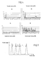
- a plot of the evaluated line length with respect to the vertical position of the corresponding horizontal line is termed a "projection profile”.
- Fig.4 shows projection profiles calculated for the four crops identified in Fig.3 based on the drawing shown in Fig.2.
- the corner that contains the title block is the bottom right-hand corner of the Fig.2 picture. It will be seen that the projection profile of this corner, shown in Fig.4d), contains a large number of peaks that are spaced apart in a substantially regular fashion. This corresponds to a large number of relatively long lines that are spaced apart in a regular fashion.
- a selection is made of which crop of the drawing corresponds to or contains the title block of the drawing based upon the peaks in the projection profiles determined for the different crops. This amounts to a detection of long lines in the image of each crop.
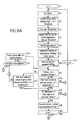
- the steps of the selection process according to this embodiment are summarised in the flow diagrams of Figs.8a) and 8b), in which Fig.8a) shows the steps involved in identifying long lines and evaluating parameters indicative of the density of long lines in each crop and Fig.8b) illustrates a preferred algorithm for selecting which crop contains the title-block, based upon the evaluated parameters.
- the decision algorithm can be speeded up by eliminating the other corners from consideration. This can be done, for example, by setting the value of a parameter N, representing the total number of crops to analyse, to less than the total number of crops, and assigning values of the index n of crops to analyse only to those crops that are likely candidates (i.e. top-left and bottom-right), or simply by not defining crops for the unlikely corners in the first place.
- N representing the total number of crops to analyse
- the projection profile is examined and peaks are identified with respect to a predetermined threshold value (here designated "Threshold”) - see steps S1-S3 of Fig.8a).
- a predetermined threshold value here designated "Threshold”
- a suitable Threshold value is 10 cm. The thus-identified peaks correspond to "long" lines present in the image.
- HiRegThick is also evaluated (step S4 of Fig.8a)) and represents the global thickness of the long lines present in this crop of the drawing.
- representation of the projection profile in terms of the list of beginning and end points of above-threshold areas can mask certain cases where there is a brief dip in the projection profile; such a case is illustrated by the circled region in Fig.6. It is not appropriate to consider the circled pair of peaks as discrete high regions, they are, in fact, portions of a common region. In other words, the pair of high regions really corresponds to a single thick line, rather than two neighbouring thin lines. Thus, in preferred embodiments of the invention, such peaks are merged into a single high region (step S5 of Fig.8a)).
- a reference value termed "MergeThreshold”
- the above-described analysis of projection profiles according to the first preferred embodiment of the invention constitutes a process for detecting relatively long image lines within the various crops of the drawing. Once the long lines have been detected, it has been found to be advantageous, according to the present invention, to define groups of lines (step S6 of Fig.8a)), and to determine which crop comprises the table to be located, by reference to one or more parameters of these groups.
- the separation, T, between adjacent peaks is considered once again. This time, two adjacent peaks are considered to belong to the same group if the separation between them is less than a reference value termed "PeakGroup". For a given set of peaks, adjacent peaks are considered pair-wise and, provided that the separation between each pair of adjacent peaks is less than PeakGroup, then the whole set of peaks belongs to the same group. For example, all of the peaks illustrated in Fig.7 would belong to a single group if T1, T2 and T3 were each less than PeakGroup.
- T1 and T2 ⁇ PeakGroup, but T3>PeakGroup, such that only the three left-hand peaks of Fig.7 belong to a common group.
- PeakGroup it is preferable to set PeakGroup to 3 cm. The result of this grouping process is a list of groups of high regions present in each crop.
- each high region corresponds to a relatively long line.
- Each group thus corresponds to a set of long lines that are pair-wise within a separation of 3 cm from each other. If the crop corresponds to the title-block of the technical drawing then there should only be one identified group of long lines. However, multiple groups of long lines can be identified for crops that contain certain types of images.
- the representative group will be the one that contains the greatest number of high regions (long lines); the number of lines per group being here designated NbReg and evaluated in step S7 of Fig.8a).
- NbReg the number of lines per group
- the first choice group and second choice group, if necessary) is validated with reference to the distance between that group and the image border. If the selected group is the closest group to the image border, then the distance is compared with a reference value termed DistBorder1 (steps S9-S10 of Fig.8a)).
- DistBorder2 the distance between this group and that closest to the border is compared with a reference value DistBorder2 (step S11 of Fig.8a)). If the compared distance is greater than the respective reference value then the selected group cannot correspond to the title block of the drawing. Based upon the inventors' findings, it is preferable to set DistBorder1 to 3 cm and DistBorder2 to 2.5 cm.
- a further test is performed to validate the group selected to represent each crop. More especially, the average distance between high regions in the representative group should be within a predetermined range of values (checked in step S14 of Fig.8a)). This average distance can be compared to the average height of a cell in the title block. Accordingly, based upon the inventors' findings in this respect, this average distance should be in the range if 0.5-3 cm (inclusive) if the representative group corresponds to the title block of the technical drawing.
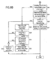
- Fig.8b shows a flow diagram representing a preferred algorithm for making the decision.
- step S18 it is determined in steps S18 to S20 whether there is a single crop having NbReg greater than that of all the other crops. If "yes”, then this single crop is selected as the table location, in step S21, and the decision process ends. However, if NbReg is zero for all crops (determined in step S18) then the decision on table location is based on the parameter HiRegThick. The crop having the greatest value of HiRegThick is determined in step S22. This crop will be selected as the table location (in step S25) and the decision process will end, provided that this value of HiRegThick has passed two tests. The first test (step S23) verifies that HiRegThick is greater than a reference value termed "MinDetect".
- MinDetect represents a measure of the minimum thickness that is likely to be exhibited by the aggregate of the long lines delimiting the cells in a title block. Based upon the inventors' findings, it is preferable to set MinDetect to 0.3 cm.
- the second test (step S24) verifies that the difference between the value of HiRegThick for the selected crop and the next highest value of HiRegThick exceeds a value termed "Tolerance". Based upon the inventors' findings, it is preferable to set Tolerance at 50% of the HiRegThick value being tested.
- the method returns an indication that no finding could be made with regard to the location of the title block (step S26). It is up to the user to determine the title block location "manually”. This is termed a "rejection".
- step S20 it is determined that the highest value of NbReg is shared by two or more crops, it is preferred to signal, once again, that no finding can be made regarding the location of the title block (step S26).
- the above description outlines the major steps of the analysis performed in the preferred embodiments of the invention.
- the above-described method for locating title blocks in technical drawings has been applied successfully, even in the case of old drawings and drawings in which the title block is partially erased. Tests measuring the reliability of the method are described in greater detail below. However, before presenting the test results it is appropriate to consider certain pre-processing stages that can be associated to the above-described method steps so as further to improve the reliability and/or speed of the title-block location process.
- the pre-processing preferably includes the following stages:
- misalignment errors can arise during the scanning process. This reduces the performance of the described method. It is therefore advantageous to detect skew and correct for it before applying the analysis steps of the present invention.
- Various algorithms for detecting and correcting skew are available on the market (see, for example, techniques mentioned in "Skew reconstruction based on maximization of variance of transition-counts" by Y. K. Chen and J. F. Wang, in Pattern Recognition 33 (2000), pp.195-208).
- the frame that generally is drawn around the principal drawing.
- information regarding the positioning of the frame is preferably used to validate the choice of representative groups for the crops (by way of the values DistBorder1 and DistBorder2).
- the preferred method for detecting the frame consists in generating horizontal and vertical projection profiles for the edges of the document and analysing these projection profiles so as to find the longest lines in the neighbourhood of the four document edges. If these lines intersect, then they are considered to represent the picture frame.
- Another method for finding the picture frame consists in detecting the largest box present on the document.
- the corner crops used to define the various crops had crop width 18 cm and crop height 13 cm. It has been found advantageous to use corner crops having these dimensions when locating title blocks in documents of A0 to A3 format. However, when locating title blocks in A4 documents, it is preferred to use end crops corresponding to the top and bottom ends of the document, giving a crop width of 21 cm (equal to the width of the sheet) and a crop height still of 13 cm.
- Fig.9 illustrates the preferred crop dimensions with respect to all of the main paper formats.
- lines are detected in the various crops of the document by evaluating the numbers of image pixels present on lines of a scanned image of the document (generating a projection profile).
- the document to be analysed is represented by data in a vector format (such as HPGL)
- the corresponding projection profile is generated directly from the vector data, which indicates the lengths and positions of lines in the image, and the thickness of the respective lines.
- lines on the document to be analysed are found by the "FAST" method of Chhabra, Misra and Arias, mentioned above.
- the line data is processed to determine the location of lines having a length above the above-mentioned Threshold value, and to assign the various lines to one or more groups with reference to the PeakGroup reference value.
- the value of the parameter HiRegThick is determined by summing the thicknesses of the lines in a given crop. The rest of the processing is substantially the same as for the first preferred embodiment of the invention except that the above-mentioned pre-processing stages are not required.
- Tests were performed on a database of scanned images of 788 technical drawings, to evaluate the effectiveness of the methods according to the present invention.
- the scanned drawings were in TIFF format and corresponded to 500 TIFF pictures for the A0 to A3 formats and 288 TIFF pictures for the A4 format.
- the resolution varied (from 200 to 400 dpi) and there were differences in scan quality.
- Some drawings had the legend partly erased, some had incomplete main frames due to scan problems and some had black borders. Legend types varied also.
- test results show that the method according to the present invention provides reliable indications of the location of title blocks in technical drawings. In particular, there is a very low confusion rate, with an incorrect legend location being indicated in 1 or fewer cases in 50. Moreover, the tests show that improvements in recognition rates can be obtained by applying deskewing and resolution-reduction to the scanned images that are analysed. It was also found in the tests that reducing resolution to 50dpi reduced the processing time for an A0 document from around 5 seconds to less than 1 second.
- crops corresponding to the corners or ends of a scanned document are analysed.
- the decision to analyse only the corners or ends of the document is advantageous in the case of title block location in technical drawings on the grounds that it speeds up the process, since the title blocks are generally located in one corner.
- crops corresponding to other portions of the document even to the extent that the set of crops covers the whole of the document.
Landscapes
- Engineering & Computer Science (AREA)
- Computer Vision & Pattern Recognition (AREA)
- Artificial Intelligence (AREA)
- Physics & Mathematics (AREA)
- General Physics & Mathematics (AREA)
- Multimedia (AREA)
- Theoretical Computer Science (AREA)
- Image Analysis (AREA)
Abstract
Description
- automatic folding of the drawing such that the title block remains visible,
- positioning of the drawing in the correct orientation (since the title block generally is located in a specified corner with respect to the image, for example, bottom right),
- in the processing of scanned images of drawings, for example using a personal computer, the title block can be displayed at an enlarged scale, to assist in manual indexing, and
- a first step is taken in the automatic indexing of drawings: once the title block has been located it is then simply a question of extracting the information contained therein.
- an identification zone giving an identification number or code to the drawing,
- a title zone, and
- a zone containing the name of the drawing's owner.
- it is a kind of table (assembly of cells), the overall assembly having a width greater than 10 cm and a height comprised between 4 cm and 28 cm;
- the height of the component cells is usually comprised between about 0.5 cm and 3 cm; and
- it is located in one of the corners of the drawing, generally the bottom right-hand corner when seen in the normal direction for reading the contents of the title block.
- verification of format (in terms of paper size) and resolution (in terms of dots per inch),
- reduction in resolution of the image to be analysed,
- deskewing of the image to be analysed, and
- detection of a frame or border surrounding the image (such a border or frame is generally present in technical drawings).
- the percentage of title blocks correctly located (termed "recognition rate"),
- the percentage of drawings for which the method did not return a finding for the legend location (termed "rejection rate"), and
- the percentage of drawings for which the method gave an incorrect location for the title block (termed "confusion rate").
| Recognition rate | Confusion rate | Rejection rate | |
| Without deskewing or reduction | 65% | 1% | 34% |
| With deskewing, without reduction (A4) | 98% | 0% | 2% |
| With deskewing, without reduction (A0-A3) | 80% | 2% | 18% |
| With deskewing and reduction to 50dpi (A0-A3) | 82% | 2% | 16% |
Claims (13)
- A method of automatically locating a table in a document, the method comprising the steps of:defining a plurality of crops of the document,for each crop of the document, determining the location of lines whose length is greater than or equal to a predetermined threshold value,evaluating at least one parameter indicative of the density of said lines, anddeciding, based on said at least one evaluated parameter, which one of said plurality of crops comprises the location of said table.
- The automatic table-locating method of claim 1, applied to title block location in technical drawings.
- The title-block locating method of claim 2, wherein said plurality of crops correspond to respective corners of the document.
- The automatic table-locating method of claim 1, 2 or 3, wherein:the evaluating step comprises defining groups of said lines, two or more adjacent lines being allocated to a common group if the separation between adjacent ones of said two or more lines is less than a reference value; andwherein the deciding step includes the step of evaluating at least one parameter of the groups of lines defined for the different crops.
- The automatic table-locating method of claim 4, wherein the decision process includes the steps of:for each crop, evaluating the number of said lines in each group, and designating as representative of the crop the group having the greatest number of lines and passing a validation test, andselecting as the crop comprising the location of the table that crop whose representative group has the greatest number of lines.
- The automatic table-locating method of claim 5, wherein the validation step comprises the step of evaluating the distance of the group from a border on the document.
- The automatic table-locating method of claim 5 or 6, wherein the validation step comprises the step of evaluating the separation between adjacent lines within the group.
- The automatic table-locating method of claim 5, 6 or 7, and comprising the step of evaluating the sum of the thicknesses of said lines for each crop and wherein, in the event that there is no crop having a representative group with the greatest number of lines, the decision process includes the step of determining whether there is a crop having an evaluated thickness sum that is significantly greater than the corresponding evaluated thickness sum for the other crops and, if so, designating that crop as the location of the table and, if not, generating a signal indicative of failure to select a location of the table.
- The automatic table-locating method of any previous claim, and comprising a preliminary step of verifying the format of the document to be analysed.
- The automatic table-locating method of any previous claim and comprising the step of determining the location of a frame present on the document and defining a border.
- The automatic table-locating method of any previous claim applied to an image of the document at a reduced resolution.
- The automatic table-locating method of any previous claim applied to a scanned image of the document, and comprising the step of deskewing the scanned image before applying the method.
- Apparatus for automatically locating a table in a document by application of the method according to any one of claims 1 to 12.
Priority Applications (1)
| Application Number | Priority Date | Filing Date | Title |
|---|---|---|---|
| EP02075780A EP1237115B1 (en) | 2001-02-22 | 2002-02-21 | Automatic table location in documents |
Applications Claiming Priority (3)
| Application Number | Priority Date | Filing Date | Title |
|---|---|---|---|
| EP01400470 | 2001-02-22 | ||
| EP01400470 | 2001-02-22 | ||
| EP02075780A EP1237115B1 (en) | 2001-02-22 | 2002-02-21 | Automatic table location in documents |
Publications (3)
| Publication Number | Publication Date |
|---|---|
| EP1237115A2 true EP1237115A2 (en) | 2002-09-04 |
| EP1237115A3 EP1237115A3 (en) | 2002-10-16 |
| EP1237115B1 EP1237115B1 (en) | 2005-05-11 |
Family
ID=26077223
Family Applications (1)
| Application Number | Title | Priority Date | Filing Date |
|---|---|---|---|
| EP02075780A Expired - Lifetime EP1237115B1 (en) | 2001-02-22 | 2002-02-21 | Automatic table location in documents |
Country Status (1)
| Country | Link |
|---|---|
| EP (1) | EP1237115B1 (en) |
Cited By (1)
| Publication number | Priority date | Publication date | Assignee | Title |
|---|---|---|---|---|
| WO2011012455A1 (en) | 2009-07-30 | 2011-02-03 | Oce-Technologies B.V. | Automatic table location in documents |
Family Cites Families (3)
| Publication number | Priority date | Publication date | Assignee | Title |
|---|---|---|---|---|
| US5680479A (en) * | 1992-04-24 | 1997-10-21 | Canon Kabushiki Kaisha | Method and apparatus for character recognition |
| JPH06203165A (en) * | 1993-01-07 | 1994-07-22 | Canon Inc | Image information processing method and apparatus |
| US6137905A (en) * | 1995-08-31 | 2000-10-24 | Canon Kabushiki Kaisha | System for discriminating document orientation |
-
2002
- 2002-02-21 EP EP02075780A patent/EP1237115B1/en not_active Expired - Lifetime
Cited By (1)
| Publication number | Priority date | Publication date | Assignee | Title |
|---|---|---|---|---|
| WO2011012455A1 (en) | 2009-07-30 | 2011-02-03 | Oce-Technologies B.V. | Automatic table location in documents |
Also Published As
| Publication number | Publication date |
|---|---|
| EP1237115B1 (en) | 2005-05-11 |
| EP1237115A3 (en) | 2002-10-16 |
Similar Documents
| Publication | Publication Date | Title |
|---|---|---|
| US6778703B1 (en) | Form recognition using reference areas | |
| CN110766014B (en) | Bill information positioning method, system and computer readable storage medium | |
| CN110147774B (en) | Table format picture layout analysis method and computer storage medium | |
| US8023741B2 (en) | Methods and systems for detecting numerals in a digital image | |
| JP3278471B2 (en) | Area division method | |
| JP3842006B2 (en) | Form classification device, form classification method, and computer-readable recording medium storing a program for causing a computer to execute these methods | |
| EP0543593B1 (en) | Method for determining boundaries of words in text | |
| US5640466A (en) | Method of deriving wordshapes for subsequent comparison | |
| US8229248B2 (en) | Methods and systems for identifying the orientation of a digital image | |
| US7251349B2 (en) | Automatic table locating technique for documents | |
| JPH11219407A (en) | Document image recognition device and storage medium for document image recognition program | |
| JP2003109007A (en) | Device, method and program for classifying slip form and image collating device | |
| EP1237115B1 (en) | Automatic table location in documents | |
| CN100486296C (en) | Information extracting method, information extracting device, information extracting program and storage medium | |
| US7227997B2 (en) | Image recognition apparatus, image recognition method, and image recognition program | |
| JPH07230525A (en) | Ruled line recognition method and table processing method | |
| US20050201639A1 (en) | Scannable form, system and method for image alignment and identification | |
| CN115841670A (en) | Operation error question collecting system based on image recognition | |
| JP3090070B2 (en) | Form identification method and device | |
| JPH06203202A (en) | Image processor | |
| US6678427B1 (en) | Document identification registration system | |
| JPH09288714A (en) | Table recognition method and device | |
| JPH0728935A (en) | Document image processor | |
| JP5006250B2 (en) | Image correction apparatus, image correction method, image correction program, and recording medium | |
| JP3381803B2 (en) | Tilt angle detector |
Legal Events
| Date | Code | Title | Description |
|---|---|---|---|
| PUAI | Public reference made under article 153(3) epc to a published international application that has entered the european phase |
Free format text: ORIGINAL CODE: 0009012 |
|
| PUAL | Search report despatched |
Free format text: ORIGINAL CODE: 0009013 |
|
| AK | Designated contracting states |
Kind code of ref document: A2 Designated state(s): AT BE CH CY DE DK ES FI FR GB GR IE IT LI LU MC NL PT SE TR |
|
| AX | Request for extension of the european patent |
Free format text: AL;LT;LV;MK;RO;SI |
|
| AK | Designated contracting states |
Kind code of ref document: A3 Designated state(s): AT BE CH CY DE DK ES FI FR GB GR IE IT LI LU MC NL PT SE TR |
|
| AX | Request for extension of the european patent |
Free format text: AL;LT;LV;MK;RO;SI |
|
| 17P | Request for examination filed |
Effective date: 20030416 |
|
| AKX | Designation fees paid |
Designated state(s): DE FR GB NL |
|
| 17Q | First examination report despatched |
Effective date: 20031210 |
|
| GRAP | Despatch of communication of intention to grant a patent |
Free format text: ORIGINAL CODE: EPIDOSNIGR1 |
|
| GRAS | Grant fee paid |
Free format text: ORIGINAL CODE: EPIDOSNIGR3 |
|
| RAP1 | Party data changed (applicant data changed or rights of an application transferred) |
Owner name: OCE PRINT LOGIC TECHNOLOGIES S.A. |
|
| GRAA | (expected) grant |
Free format text: ORIGINAL CODE: 0009210 |
|
| AK | Designated contracting states |
Kind code of ref document: B1 Designated state(s): DE FR GB NL |
|
| REG | Reference to a national code |
Ref country code: GB Ref legal event code: FG4D |
|
| REG | Reference to a national code |
Ref country code: IE Ref legal event code: FG4D |
|
| REF | Corresponds to: |
Ref document number: 60204066 Country of ref document: DE Date of ref document: 20050616 Kind code of ref document: P |
|
| PLBE | No opposition filed within time limit |
Free format text: ORIGINAL CODE: 0009261 |
|
| STAA | Information on the status of an ep patent application or granted ep patent |
Free format text: STATUS: NO OPPOSITION FILED WITHIN TIME LIMIT |
|
| ET | Fr: translation filed | ||
| 26N | No opposition filed |
Effective date: 20060214 |
|
| REG | Reference to a national code |
Ref country code: FR Ref legal event code: PLFP Year of fee payment: 15 |
|
| REG | Reference to a national code |
Ref country code: FR Ref legal event code: PLFP Year of fee payment: 16 |
|
| REG | Reference to a national code |
Ref country code: FR Ref legal event code: PLFP Year of fee payment: 17 |
|
| PGFP | Annual fee paid to national office [announced via postgrant information from national office to epo] |
Ref country code: NL Payment date: 20180223 Year of fee payment: 17 |
|
| PGFP | Annual fee paid to national office [announced via postgrant information from national office to epo] |
Ref country code: DE Payment date: 20180219 Year of fee payment: 17 Ref country code: GB Payment date: 20180216 Year of fee payment: 17 |
|
| PGFP | Annual fee paid to national office [announced via postgrant information from national office to epo] |
Ref country code: FR Payment date: 20180222 Year of fee payment: 17 |
|
| REG | Reference to a national code |
Ref country code: DE Ref legal event code: R119 Ref document number: 60204066 Country of ref document: DE |
|
| REG | Reference to a national code |
Ref country code: NL Ref legal event code: MM Effective date: 20190301 |
|
| GBPC | Gb: european patent ceased through non-payment of renewal fee |
Effective date: 20190221 |
|
| PG25 | Lapsed in a contracting state [announced via postgrant information from national office to epo] |
Ref country code: NL Free format text: LAPSE BECAUSE OF NON-PAYMENT OF DUE FEES Effective date: 20190301 Ref country code: DE Free format text: LAPSE BECAUSE OF NON-PAYMENT OF DUE FEES Effective date: 20190903 Ref country code: GB Free format text: LAPSE BECAUSE OF NON-PAYMENT OF DUE FEES Effective date: 20190221 |
|
| PG25 | Lapsed in a contracting state [announced via postgrant information from national office to epo] |
Ref country code: FR Free format text: LAPSE BECAUSE OF NON-PAYMENT OF DUE FEES Effective date: 20190228 |