EP1237088A2 - Storage system having trace information fetching structure and method of fetching trace information - Google Patents
Storage system having trace information fetching structure and method of fetching trace information Download PDFInfo
- Publication number
- EP1237088A2 EP1237088A2 EP01117566A EP01117566A EP1237088A2 EP 1237088 A2 EP1237088 A2 EP 1237088A2 EP 01117566 A EP01117566 A EP 01117566A EP 01117566 A EP01117566 A EP 01117566A EP 1237088 A2 EP1237088 A2 EP 1237088A2
- Authority
- EP
- European Patent Office
- Prior art keywords
- trace information
- information
- level devices
- trace
- channel controller
- Prior art date
- Legal status (The legal status is an assumption and is not a legal conclusion. Google has not performed a legal analysis and makes no representation as to the accuracy of the status listed.)
- Withdrawn
Links
Images


Classifications
-
- G—PHYSICS
- G06—COMPUTING OR CALCULATING; COUNTING
- G06F—ELECTRIC DIGITAL DATA PROCESSING
- G06F11/00—Error detection; Error correction; Monitoring
- G06F11/30—Monitoring
- G06F11/34—Recording or statistical evaluation of computer activity, e.g. of down time, of input/output operation ; Recording or statistical evaluation of user activity, e.g. usability assessment
- G06F11/3466—Performance evaluation by tracing or monitoring
- G06F11/348—Circuit details, i.e. tracer hardware
-
- G—PHYSICS
- G06—COMPUTING OR CALCULATING; COUNTING
- G06F—ELECTRIC DIGITAL DATA PROCESSING
- G06F11/00—Error detection; Error correction; Monitoring
- G06F11/22—Detection or location of defective computer hardware by testing during standby operation or during idle time, e.g. start-up testing
- G06F11/2268—Logging of test results
-
- G—PHYSICS
- G06—COMPUTING OR CALCULATING; COUNTING
- G06F—ELECTRIC DIGITAL DATA PROCESSING
- G06F11/00—Error detection; Error correction; Monitoring
- G06F11/30—Monitoring
- G06F11/34—Recording or statistical evaluation of computer activity, e.g. of down time, of input/output operation ; Recording or statistical evaluation of user activity, e.g. usability assessment
- G06F11/3466—Performance evaluation by tracing or monitoring
- G06F11/349—Performance evaluation by tracing or monitoring for interfaces, buses
Definitions
- the present invention relates to a storage, a storage system having a data fetching method, particularly a trace function, to trace a command sequence in an input/output (I/O) interface, and a method of fetching trace information thereof.
- the data is used as follows.
- a command sequence before and after occurrence of a failure is used to detect a process to the failure and direct causes of the failure.
- the data is used in the performance analysis as follows.
- a pattern of the command sequence issuance is determined to detect processing in the storage system which exerts influence on the performance.
- trace information of such a command sequence is in general fetched by, for example, a utility "generalized trace facility (GTF)" of IBM.
- GTF generalized trace facility
- SCSI analyzer can be connected to a storage system to fetch trace information.
- GTF is a function installed only in a main frame system, and an equivalent trace function is not satisfactory supported in an open system at present. Therefore, there possibly occurs a case in which a failure taking place in an open system cannot be easily analyzed.
- SCSI analyzer it is necessary to once stop a path on the host side connected to the pertinent SCSI path. This possibly exerts adverse influence on business of the customer, and hence it is difficult to fetch trace information at an appropriate time.
- JP-A-2000-187621 describes a technique in which information on a bus of the SCSI and information on a processor bus are traced and the trace is stopped at occurrence of an abnormality.
- a trace area reserved is insufficient, new trace information overlaps old trace information or the trace is stopped when the trace area becomes full of information. Consequently, expected information cannot be fetched depending on cases.
- JP-A-11-212821 describes a technique in which the trace information is fetched in a trace buffer with a limited capacity by using a data compression/expansion function of a magnetic tape controller. 'However, also in this technique, since the trace information is fetched in the buffer with a physically limited capacity, even when trace information is fetched for a long period of time for performance analysis, there occurs a case in which information is insufficient. This disadvantageously leads to a problem that the performance analysis cannot be conducted.
- the inventor considers that a fundamental cause of three problems above is that all trace information in the storage system is treated as data dedicated to the storage system. Therefore, the inventor recognizes that a dedicated buffer and a dedicated fetching tool are necessary in the storage system and hence cause various restrictions.
- Trace information is not stored in a memory of the processor which processes data input/output operations between a host and a storage, but is temporarily stored as part of user data in a buffer in the controller or in a cache memory. The data is then sequentially collected onto a control medium of the higher-level device, a personal computer (PC), or the like.
- PC personal computer
- a storage system including a storage control unit connected to higher-level devices and a plurality of storages connected to the storage control unit for storing data from the higher-level devices.
- the storage control unit includes a channel controller for establishing interface for the higher-level devices, the channel controller including trace information representing details of the interface; and storage units for storing the trace information from the channel controller in a format which can be accessed by the higher-level devices.
- Fig. 1 shows a storage system in an embodiment of the present invention in a hardware configuration diagram.
- the storage system includes a controller 20 and a plurality of storages 50 to 53.
- the storage system shown in Fig. 1 further includes a service processor 30 to maintain and to control the controller 20 and the storages 50 to 53.
- a service processor 30 to maintain and to control the controller 20 and the storages 50 to 53.
- the controller 20 includes channel controllers 21, device controllers 22, a cache memory 23, and a common memory 24.
- the channel controller 21 is connected to a host 10 or a personal computer (PC) 40 to receive data input/output (I/O) requests from the host 10, to write data from the host 10 in a cache memory 23, and to transfer data from the cache memory 23 to the host 10.
- the device controller 22 writes data from the cache memory 23 in the respective storages 50, 51, 52, and 53 and transfers data from the respective storages 50 to 53 to the cache memory 23.
- the common memory 24 keeps information (to be referred to as configuration information herebelow) necessary for the controller 20 to control the entire storage system.
- Each of the channel controllers 21 includes a microprocessor (MP) 25 to conduct the control operation above and each of the device controllers 22 includes a microprocessor (MP) 26 to conduct the control operation above.
- MP microprocessor
- Each of the MPs is also connected to the common memory 24 such that the MP conducts I/O control from the host and I/O control with the storages 50 to 53 by referring to the configuration information.
- the service processor 30 is a maintenance terminal including a graphic user interface (GUI).
- the service processor 30 is connected to each of the MPs 25 and 26 and has a function in which then service processor 30 issues a maintenance indication to each MP 25 or 26 in response to a maintenance operation, detects information regarding failures taking place in the storage system, and notifies the failures to a maintenance center.
- the channel controllers 21 and the device controllers 22 access the cache memory 23 and the common memory 24 via control lines indicated by bold lines.
- the service processor 30 sends indications for the definition, modification, and the like of the configuration to the controller 20.
- the PC 40 is connected to the channel controller 21 to collect the traced information.
- the trace processing is executed by the MPs 25 and 26.
- the MP 25 or 26 having received a trace information fetching indication from the service processor 30, the host 10, or the PC 40 reads trace information thereof or the pertinent MP 25 or 26 identifies trace information and transfers the trace information ;;to the specified service processor 30, the host 10, or the PC 40. Furthermore, an indication of the trace processing can be issued from the service processor 30, the host 10, or the PC 40.
- the trace processing indication is received by, for example, the MP 25, the MP 25 once writes, while executing the trace processing, trace information in the cache memory 23 in a data format equal to that of user data.
- the trace information written in the cache memory 23 is stored by the MP 26 of the device controller 22 in the storage 50, 51, 52, or 53.
- a storage destination is written in a particular volume of either one of the storages 50 to 53, it is also possible to specify that the information is only temporarily stored in the cache memory 23. This is used by the PC 40 to collect and to refer to the trace information temporarily stored in the cache memory 23.
- the storage destination specification is defined as a parameter of the trace processing start indication.
- an area is reserved as a trace information dedicated area in the cache memory 23 in the data format equal to that of the user data. This prevents the device controllers 22 to store data in the storages 50, 51, 52, and 53.
- the trace start indication When the trace start indication is issued, it is also possible to indicate a trace termination condition. For example, a fetching time is specified such that after a lapse of the fetching time, the trace processing is terminated. Or, a trace information fetching amount is indicated such that when an amount of fetched trace information exceeds the specified fetching amount, the trace processing is terminated.
- the trace termination condition is checked during the trace information fetching processing, and the trace fetching processing is terminated when the termination is determined according to the condition. Moreover, it is possible to terminate the trace information fetching processing by issuing a trace termination indication.
- Fig. 2 is a flowchart showing processing of the I/O trace information fetching method.
- the service processor 30 indicates the MP 25 to fetch trace information and to store the information in the cache memory 23 or the storage 50, 51, 52, or 53.
- the service processor issues a fetching indication to the MP 25.
- a trace information storage destination namely, the cache memory 23 or the storage 50, 51, 52, or 53 is also indicated together with a parameter, which will be described later.
- the MP 25 creates, in step 202, information in the common memory 24 to notify the reception of the fetching indication to other MPs 25.
- the MP 25 having received the indication in step 203 identifies trace information.
- the MP 25 further determines in step 204, according to the indication of the trace information storage destination, that the trace information is temporarily stored in the cache memory 23 or is stored as data of the specified storage 50, 51, 52, or 53.
- the MP 25 writes the trace information as data of the specified storage in the cache memory 23.
- the trace information is in a format equal to that of the user data.
- the trace information written in the cache memory 23 is written by the device controller 22 in the pertinent storage and the trace information of the cache memory 23 is discarded (step 205), and the processing proceeds to step 209.
- step 209 the MP 25 in the trace information readout operation checks to determine the termination of the trace processing. If the trace processing termination condition is not satisfied, the processing returns to step 203. Thereafter, the trace information is stored in the specified storage until the trace processing termination condition is satisfied.
- step 206 the MP 25 having received the fetching indication saves the trace information in the cache memory 23, specifically, in the trace information dedicated area.
- steps 207 and 208 the PC 40 connected to the channel controller 21 collects the trace information.
- step 207 the MP 25 executes a transfer request, to the PC 40 connected thereto, for the trace information temporarily stored in the cache memory 23.
- the PC 40 executes a read request.
- the MP 25 transfers the pertinent trace information from the cache memory 23 to the PC 40.
- step 208 the processing proceeds to step 209 to determine the termination of the trace. If the trace termination condition is not satisfied, the processing returns to step 203. Thereafter, the trace information is stored in the storage until the trace termination condition is satisfied.
- one of the MPs 25 receives a trace information fetching indication from the service processor 30.
- the MP 26 identifies, like the MP 25, trace information in the MP 26 and temporarily stores the trace information in the cache memory 23 or in one of the storages specified by the device controller 22.
- the trace information is stored in these storages in a data format equal to that of the user data.
- the trace information fetching indication can also be issued by the host 10 and the PC 40.
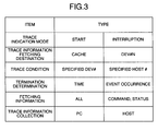
- Fig. 3 is an example of parameters of trace modes for an trace information fetching operation indicated by the service processor 30.
- the parameters specify a trace indication mode, a trace information fetching destination, a trace condition, termination determination, and fetching information.
- Fig. 3 shows two items specifiable by each of the parameters.
- One of the items is "start” or “interruption” for the trace indication mode.
- Start means a trace information fetching start indication.
- "Interruption” means a trace information fetching interruption indication.
- As the trace information fetching destination "cache” or particular "DEV#” is specified.
- “Cache” is specified when it is desired that information is temporarily stored in the cache memory 23.
- DEV# is specified when it is desired that information is stored in a particular device.
- DEV# means a device number of a storage destination device.
- trace condition there exist two types, namely, "specified DEV#” and “specified host #”.
- Specified DEV# means that only history of I/O processing of the specified device is stored as trace information.
- Specified host # means that processing history of only I/O from the specified host is stored as trace information.
- termination determination there exist two types, namely, "time” and “event occurrence”.
- “Time” is a time at which trace information is fetched. This means that the trace information fetching is terminated when the specified time lapses after the trace information fetching is started.
- Event occurrence means that the trace information fetching is terminated (or interrupted) when "interruption” is indicated.
- the MP 25 executes a trace information transfer request to the PC 40 such that trace information is fetched by the PC 40 from the cache memory 23. This is as described using the flowchart of Fig. 2.
- the service processor 30 issues an indication to the MP 26 of the device controller 22, and in response to a transfer request issued by the pertinent MP 26, trace information is read from the associated storage and is transferred to the service processor 30.
- the host 10 issues a trace information fetching indication to the MP 25 of the channel controller 21. That is, in response to the indication from the host 10, processing is executed as follows.
- trace information is read from the cache memory 23 and is transferred to the host 10.
- the indication from the host 10 is issued using, for example, a mode select command of the SCSI command.
- This command has a field of "vendor unique page", and the vendor can freely define the field for use.
- the host 10 specifies in this page parameters shown in Fig. 3 and then issues the mode select command.
- the MP 25 of the channel controller 21 of the controller 20 refers to "command mode select" and the vendor unique page to start the trace processing.
- the MP 25 having received the command issues a transfer request. Therefore, trace information is transferred to the host 10.
- the host 10 conducts a trace information reading operation for the storage as the trace information storage destination. That is, in response to a transfer request issued by the MP 26, trace information is transferred to the host 10. Therefore, the trace information stored in the storage has a data format equal to that of the user data.
- the host can directly fetch the trace information from the cache memory 23 or the storages 50 to 53, it is possible that the host 10 edits the trace information and issues again an I/O request according to the trace information to conduct a reproduction test for the failure analysis. Analysis of an I/O issuance pattern of the storage as a trace target can also be easily conducted by the host 10, and hence the trace information can be efficiently utilized.
- the trace information identified by the MP 25 or 26 is stored in the cache memory 23, it is also possible to convert the format of information into the data format of the ordinary I/O data.
- the data format need only match the data format used to store I/O data received from the higher-level device in the storages 50 to 53 or the data format used to store data in the cache memory 23. Resultantly, the trace information stored in the cache memory 23 and the storages 50 to 53 can be treated as user data, and hence it is not required for the cache memory 23, the storages 50 to 53, and the MPs 25 and 26 which control these storing components to conduct particular recognition for the trace information.
- trace information is stored as user data, it is practical if there exists a method to assign an identifier thereto to acquire the information. To implement the method, it is not changed that when the trace information is stored, the trace information is stored in the data format of user data. However, it is only necessary to write, as header information, an identifier indicating that the data is trace information, day and time when the data is fetched, an identifier to discriminate the trace information, and the like.
- the identifier for the discrimination may be, for example, a sequential number which is incrementally increased each time trace information is fetched or an item obtained by combining the sequential number with the day and time when the information is fetched.
- the side to obtain the trace information can determine whether or not the obtained data includes header information of the trace information.
- the side to obtain the information must make a search through the written trace information, and it is to be noted that a position at which the information is written must be beforehand memorized.
- a table to store fetching positions is reserved in the common memory 24 on the side of the controller 20.
- the trace fetching method description has been mainly given of a case in which the method is applied to one of the processors 25 and 26. It is also necessary that the trace information fetching operation is conducted for a plurality of processors at the same time. If processing timing between the MPs can be comprehensively analyzed, the trace information is more useful for the detection of causes at occurrence of a failure and for performance analysis. In this case, it is only necessary for the service processor 30, the host 10, and the PC 40 to respectively issue the trace information fetching indications to the MPs. The respective MPs can independently execute the trace processing. However, for the trace information fetching start indication, an issuing method thereof must be appropriately devised for the following reason.
- the MPs identify trace information, it is possible to directly process an ordinary I/O from the host 10 as in the SCSI analyzer. Therefore, it is not required that the processing on the side of the host 10 is stopped by the trace information fetching operation.
- trace information As above, by treating trace information as part of user data, it is possible to fetch a large amount of trace information. Moreover, since the trace information is temporarily accumulated in a cache memory which can be accessed by a plurality of MPs, it is possible to keep consistency of the fetched trace information. Furthermore, since the MPs identify the trace information, it is possible to remove any direct influence to business of the customer which takes place when the SCSI analyzer is used.
Landscapes
- Engineering & Computer Science (AREA)
- General Engineering & Computer Science (AREA)
- Theoretical Computer Science (AREA)
- Computer Hardware Design (AREA)
- Quality & Reliability (AREA)
- Physics & Mathematics (AREA)
- General Physics & Mathematics (AREA)
- Debugging And Monitoring (AREA)
- Memory System Of A Hierarchy Structure (AREA)
Abstract
Description
Claims (10)
- A storage system having a trace information fetching function including storage control means (20) connected to higher-level devices (10, 30, 40), and a plurality of storages (50-53) connected to said storage control means for storing data from said higher-level devices, wherein said storage control means comprises:a channel controller (21) for establishing interface for said higher-level devices, said channel controller including trace information representing details of the interface; andstorage means (23, 50-53) for storing the trace information from said channel controller in a format to be accessed by said higher-level devices.
- The storage system of claim 1, wherein said storage means (23, 50-53) includes
a cache memory (23) for storing the trace information from said channel controller in a format to be accessed by said higher-level devices, and/or
storages (50-53) for storing the trace information from said channel controller in a format to be accessed by said higher-level devices. - The storage system of claim 1 or 2, wherein said storage control means (20) further comprises
a device controller (22) for controlling storages (50-53) as said storage means for storing the trace information from said channel controller in a format to be accessed by said higher-level devices, and/or
a plurality of channel controllers (21) respectively corresponding to said higher-level devices, and a common memory (24) for storing, when at least one of said channel controllers receives information of a trace information fetching indication from one of said high-level devices, the indication information to notify the indication information to other channel controllers. - The storage system of claim 3, wherein when one of said channel controllers (21) receives a trace information fetching indication from one of said higher-level devices, said channel controller refers to the indication information of the other channel controllers (21) stored in said common memory (24).
- The storage system of claim 1, wherein said higher-level device issues a trace information fetching indication to at least one of a plurality of channel controllers (21), or to at least one of a plurality of device controllers (22).
- The storage system of any preceding claim, wherein said higher-level devices include a personal computer (PC; 40), a service processor (30), and a host computer (10).
- A method of fetching trace information for use with a system comprising a plurality of higher-level devices (40, 30, 10), storage means (50-53), and storage control means (20) disposed between the higher-level devices and the storage means, the storage control means including a channel controller (21) for establishing interface for the higher-level devices and the storage means, the trace information representing details of said interface, comprising the steps of:(a) indicating fetching of trace information from the higher-level devices (40, 30, 10) to the channel controller (21);(b) storing, by the channel controller (21) having received the fetching indication, the indicated information in a common memory (24);(c) identifying, by the channel controller (21), trace information thereof, determining according to the indicated information one of the storage means (23, 50-53) to store trace information, and storing the trace information in the storage means;(d) issuing a request from the channel controller (21) to the higher-level devices (40, 30, 10), the request indicating acquisition of the trace information stored in the storage means (23, 50-53); and(e) transferring the trace information stored in the storage means (23, 50-53) from the channel controller (21) to the higher-level devices (40, 30, 10).
- The method of claim 7, wherein said step (c) includes the steps of:identifying, by the channel controller (21), trace information thereof; anddetermining according to the indicated information that the storage means is the cache memory (23), and storing the trace information in the cache memory (23), ordetermining according to the indicated information that the storage means is the storages (50-53), and storing the trace information in the storages.
- The method of claim 7, wherein said step (d) includes the step of issuing a request from the channel controller (21) to the higher-level devices (40, 30, 10), the request indicating
acquisition of the trace information stored in the cache memory (23), or
acquisition of the trace information stored in the storages (50-53). - The method of claim 7, wherein:said step (c) includes the steps of:identifying, by the channel controller (21), trace information thereof;determining according to the indicated information that the storage means is the cache memory (23) and temporarily storing the trace information in the cache memory (23); andstoring thereafter the trace information stored in the cache memory (23) in the storages (50-53); andsaid step (d) includes the step of issuing a request from the channel controller (21) to the higher-level devices (40, 30, 10), the request indicating acquisition of the trace information stored in the storages (50-53).
Applications Claiming Priority (2)
| Application Number | Priority Date | Filing Date | Title |
|---|---|---|---|
| JP2001057623 | 2001-03-02 | ||
| JP2001057623A JP2002259065A (en) | 2001-03-02 | 2001-03-02 | Storage system with trace information collection mechanism |
Publications (2)
| Publication Number | Publication Date |
|---|---|
| EP1237088A2 true EP1237088A2 (en) | 2002-09-04 |
| EP1237088A3 EP1237088A3 (en) | 2006-05-31 |
Family
ID=18917468
Family Applications (1)
| Application Number | Title | Priority Date | Filing Date |
|---|---|---|---|
| EP01117566A Withdrawn EP1237088A3 (en) | 2001-03-02 | 2001-07-20 | Storage system having trace information fetching structure and method of fetching trace information |
Country Status (3)
| Country | Link |
|---|---|
| US (1) | US6934891B2 (en) |
| EP (1) | EP1237088A3 (en) |
| JP (1) | JP2002259065A (en) |
Cited By (2)
| Publication number | Priority date | Publication date | Assignee | Title |
|---|---|---|---|---|
| CN1313914C (en) * | 2003-11-28 | 2007-05-02 | 株式会社日立制作所 | Storage control apparatus and a control method thereof |
| EP1662392A3 (en) * | 2004-11-08 | 2008-04-30 | Hitachi, Ltd. | Identifying the extent that a fault on a storage device has to a replication process involving said device |
Families Citing this family (13)
| Publication number | Priority date | Publication date | Assignee | Title |
|---|---|---|---|---|
| US6886020B1 (en) * | 2000-08-17 | 2005-04-26 | Emc Corporation | Method and apparatus for storage system metrics management and archive |
| JP2004234558A (en) * | 2003-01-31 | 2004-08-19 | Hitachi Ltd | Storage device control device and program |
| JP2004234555A (en) * | 2003-01-31 | 2004-08-19 | Hitachi Ltd | Storage system control method, storage system, and program |
| JP4342804B2 (en) * | 2003-01-31 | 2009-10-14 | 株式会社日立製作所 | Storage system control method, storage system, and program |
| JP4401788B2 (en) * | 2004-01-06 | 2010-01-20 | 株式会社日立製作所 | Storage controller |
| JP2005196673A (en) | 2004-01-09 | 2005-07-21 | Hitachi Ltd | Storage control system for storing operation information |
| CN100442244C (en) * | 2004-05-12 | 2008-12-10 | Nxp股份有限公司 | Data processing apparatus, system and method with trace co-processor |
| US20080244327A1 (en) * | 2007-03-28 | 2008-10-02 | Seagate Technology Llc | Trace device for monitoring electronic device |
| JP2009064340A (en) * | 2007-09-07 | 2009-03-26 | Murata Mach Ltd | Data transfer system |
| JP5200512B2 (en) * | 2007-11-30 | 2013-06-05 | ダイキン工業株式会社 | History management device |
| US8499200B2 (en) * | 2010-05-24 | 2013-07-30 | Ncr Corporation | Managing code-tracing data |
| US8972791B2 (en) * | 2012-01-31 | 2015-03-03 | Ncr Corporation | Managing code-tracing data |
| JP5962145B2 (en) * | 2012-03-30 | 2016-08-03 | 日本電気株式会社 | Disk array device, disk array controller, log output method and program |
Family Cites Families (13)
| Publication number | Priority date | Publication date | Assignee | Title |
|---|---|---|---|---|
| US3748650A (en) * | 1972-08-21 | 1973-07-24 | Ibm | Input/output hardware trace monitor |
| US4949252A (en) * | 1985-10-17 | 1990-08-14 | Technology 80, Inc. | Computer channel analyzer with monitoring and selective display of predetermining events and related data |
| DE4126465C1 (en) * | 1991-08-09 | 1992-08-20 | Siemens Nixdorf Informationssysteme Ag, 4790 Paderborn, De | |
| US6047353A (en) * | 1997-05-07 | 2000-04-04 | Emc Corporation | Method and apparatus for monitoring of host activities relating to an attached storage device |
| JP3097076B2 (en) | 1998-01-22 | 2000-10-10 | 日本電気株式会社 | Trace data collection method |
| US5968188A (en) * | 1998-03-10 | 1999-10-19 | Grammar Engine | System for providing real-time code coverage |
| US6438715B1 (en) * | 1998-05-04 | 2002-08-20 | Stmicroelectronics N.V. | Trace operations in an integrated circuit for a disk drive |
| JP2000187621A (en) | 1998-12-22 | 2000-07-04 | Nec Ibaraki Ltd | Scsi controller |
| US6587957B1 (en) * | 1999-07-30 | 2003-07-01 | Emc Corporation | Disk drive controller for controlling data flow therethrough by switching to secondary bus to receive clock pulses when a failure on master bus is detected |
| US6530076B1 (en) * | 1999-12-23 | 2003-03-04 | Bull Hn Information Systems Inc. | Data processing system processor dynamic selection of internal signal tracing |
| US6718294B1 (en) * | 2000-05-16 | 2004-04-06 | Mindspeed Technologies, Inc. | System and method for synchronized control of system simulators with multiple processor cores |
| US6813731B2 (en) * | 2001-02-26 | 2004-11-02 | Emc Corporation | Methods and apparatus for accessing trace data |
| US6615371B2 (en) * | 2002-03-11 | 2003-09-02 | American Arium | Trace reporting method and system |
-
2001
- 2001-03-02 JP JP2001057623A patent/JP2002259065A/en active Pending
- 2001-07-19 US US09/907,618 patent/US6934891B2/en not_active Expired - Fee Related
- 2001-07-20 EP EP01117566A patent/EP1237088A3/en not_active Withdrawn
Cited By (4)
| Publication number | Priority date | Publication date | Assignee | Title |
|---|---|---|---|---|
| CN1313914C (en) * | 2003-11-28 | 2007-05-02 | 株式会社日立制作所 | Storage control apparatus and a control method thereof |
| US7219192B2 (en) | 2003-11-28 | 2007-05-15 | Hitachi, Ltd. | Storage system and method for a storage control apparatus using information on management of storage resources |
| EP1662392A3 (en) * | 2004-11-08 | 2008-04-30 | Hitachi, Ltd. | Identifying the extent that a fault on a storage device has to a replication process involving said device |
| US7415629B2 (en) | 2004-11-08 | 2008-08-19 | Hitachi, Ltd. | Method for managing pair states in a storage system |
Also Published As
| Publication number | Publication date |
|---|---|
| EP1237088A3 (en) | 2006-05-31 |
| JP2002259065A (en) | 2002-09-13 |
| US20020124140A1 (en) | 2002-09-05 |
| US6934891B2 (en) | 2005-08-23 |
Similar Documents
| Publication | Publication Date | Title |
|---|---|---|
| EP0560343B1 (en) | Input-output control system and input-output control method in the system | |
| US6934891B2 (en) | Storage system having trace information fetching structure and method of fetching the same | |
| EP0848321B1 (en) | Method of data migration | |
| US6636876B1 (en) | Database copy apparatus, database copy method and recording medium recorded with database copy program | |
| CN109669635B (en) | Command LBA (logical block addressing) coincidence detection method and device for solid-state storage master control chip | |
| US5060142A (en) | System which matches a received sequence of channel commands to sequence defining rules for predictively optimizing peripheral subsystem operations | |
| EP0939371B1 (en) | Memory subsystem and method of reorganising multiplexed data | |
| KR100432849B1 (en) | Magnetic disk, method of accessing magnetic disk device, and recording medium storing disk access control program for magnetic disk device | |
| JPH10105502A (en) | Peripheral equipment controller | |
| JP2004264970A (en) | Program, information processing apparatus, and log data output method in information processing apparatus | |
| US6088818A (en) | Data read apparatus and data read method | |
| US7243113B2 (en) | Information management system, information management method, and storage medium for managing execution records | |
| JPH0981405A (en) | Computer system retry processor | |
| JPH10312329A (en) | Data backup / restore device | |
| JPH0793101A (en) | Data backup device | |
| US6345312B1 (en) | Selectively dummying a data pipe transparent to a writer application | |
| JPH0553881A (en) | Logout method | |
| US20090292866A1 (en) | Disk apparatus and command processing method | |
| JP3394879B2 (en) | Data recording medium conversion processing method and apparatus | |
| KR960003982B1 (en) | Overload adaptive controlling method for electronic switching system | |
| CN118426670A (en) | Data processing method and data processing device | |
| JPH0612359A (en) | Input / output control method and system | |
| JPH0353655B2 (en) | ||
| JPH05216718A (en) | How to debug | |
| JPH1091511A (en) | Backup system |
Legal Events
| Date | Code | Title | Description |
|---|---|---|---|
| PUAI | Public reference made under article 153(3) epc to a published international application that has entered the european phase |
Free format text: ORIGINAL CODE: 0009012 |
|
| AK | Designated contracting states |
Kind code of ref document: A2 Designated state(s): AT BE CH CY DE DK ES FI FR GB GR IE IT LI LU MC NL PT SE TR |
|
| AX | Request for extension of the european patent |
Free format text: AL;LT;LV;MK;RO;SI |
|
| PUAL | Search report despatched |
Free format text: ORIGINAL CODE: 0009013 |
|
| 17P | Request for examination filed |
Effective date: 20060331 |
|
| AK | Designated contracting states |
Kind code of ref document: A3 Designated state(s): AT BE CH CY DE DK ES FI FR GB GR IE IT LI LU MC NL PT SE TR |
|
| AX | Request for extension of the european patent |
Extension state: AL LT LV MK RO SI |
|
| 17Q | First examination report despatched |
Effective date: 20060725 |
|
| AKX | Designation fees paid |
Designated state(s): DE FR GB |
|
| STAA | Information on the status of an ep patent application or granted ep patent |
Free format text: STATUS: THE APPLICATION IS DEEMED TO BE WITHDRAWN |
|
| 18D | Application deemed to be withdrawn |
Effective date: 20140201 |