EP1237033A2 - Hollow light-mixing rod and manufacturing method for the same - Google Patents
Hollow light-mixing rod and manufacturing method for the same Download PDFInfo
- Publication number
- EP1237033A2 EP1237033A2 EP01130317A EP01130317A EP1237033A2 EP 1237033 A2 EP1237033 A2 EP 1237033A2 EP 01130317 A EP01130317 A EP 01130317A EP 01130317 A EP01130317 A EP 01130317A EP 1237033 A2 EP1237033 A2 EP 1237033A2
- Authority
- EP
- European Patent Office
- Prior art keywords
- section
- cross
- face
- side parts
- mixing rod
- Prior art date
- Legal status (The legal status is an assumption and is not a legal conclusion. Google has not performed a legal analysis and makes no representation as to the accuracy of the status listed.)
- Withdrawn
Links
Images


Classifications
-
- G—PHYSICS
- G02—OPTICS
- G02B—OPTICAL ELEMENTS, SYSTEMS OR APPARATUS
- G02B27/00—Optical systems or apparatus not provided for by any of the groups G02B1/00 - G02B26/00, G02B30/00
- G02B27/09—Beam shaping, e.g. changing the cross-sectional area, not otherwise provided for
- G02B27/0938—Using specific optical elements
- G02B27/0994—Fibers, light pipes
-
- G—PHYSICS
- G02—OPTICS
- G02B—OPTICAL ELEMENTS, SYSTEMS OR APPARATUS
- G02B27/00—Optical systems or apparatus not provided for by any of the groups G02B1/00 - G02B26/00, G02B30/00
- G02B27/09—Beam shaping, e.g. changing the cross-sectional area, not otherwise provided for
-
- G—PHYSICS
- G02—OPTICS
- G02B—OPTICAL ELEMENTS, SYSTEMS OR APPARATUS
- G02B6/00—Light guides; Structural details of arrangements comprising light guides and other optical elements, e.g. couplings
- G02B6/24—Coupling light guides
- G02B6/26—Optical coupling means
- G02B6/28—Optical coupling means having data bus means, i.e. plural waveguides interconnected and providing an inherently bidirectional system by mixing and splitting signals
- G02B6/2804—Optical coupling means having data bus means, i.e. plural waveguides interconnected and providing an inherently bidirectional system by mixing and splitting signals forming multipart couplers without wavelength selective elements, e.g. "T" couplers, star couplers
- G02B6/2808—Optical coupling means having data bus means, i.e. plural waveguides interconnected and providing an inherently bidirectional system by mixing and splitting signals forming multipart couplers without wavelength selective elements, e.g. "T" couplers, star couplers using a mixing element which evenly distributes an input signal over a number of outputs
Definitions
- the invention relates to a manufacturing method for a hollow mixing rod and to one Hollow mixing rod with four side parts, each with a reflective inside, one side each a cavity extending from a light entry surface to a light exit surface forms a square cross section.
- a manufacturing method for a hollow mixing rod To provide with the hollow mixing rod can be easily and accurately manufactured, even if two cross-sectional sides of the cavity converge at an angle that is not equal to 90 °. Furthermore, a hollow mixing rod of the type mentioned should be improved so that it is as easy to manufacture as possible.
- this object is achieved by the production method for a hollow mixing rod has a cavity with a square cross section, solved with the following steps: manufacture one first and a second side part, each of a T-shaped cross section with a crossbar and has a central web projecting therefrom, which has a central web facing away from the transverse web, reflective end face and seen in cross section a first and a second from the end face includes the side surface extending to the crosspiece, the end surface at least in the first side part and the first side surface seen in cross section converge at an angle that is not equal 90 °, manufacture a third and fourth side part, each with a reflective, flat Inside, assembling the four side panels so that the end face of the first and second Side part facing each other and that the reflective insides of the third and fourth Side part seen in cross section run parallel to each other and with their edge sections rest on the side surfaces of the crossbars, so that the cavity to form the square Cross-section is limited.
- the ground and optionally polished end surface can still be mirrored. You can do this, for example, by mirroring with a silver layer or by applying a dielectric reflecting layer. ever Depending on the type of mirror layer, a protective layer can optionally be applied to the mirror layer be applied.
- the end surface can also be formed by milling instead of grinding, preferably the End surface is still polished.
- the side parts can be made of glass, metal, metal alloys, ceramic or plastic. If plastic is used, the first and second side part can be made, for example, by Injection molding can be formed with the tapered end surface.
- the end face may be preferred still be reworked if the flatness of the end surface is to be improved. Here too the end face will be mirrored. If metal or a metal alloy is used, the reflective property of the end surface can only be produced by polishing. Even with these Materials can already have the side parts with beveled end surfaces such. B. by casting process be formed. Alternatively, of course, is also grinding or milling to chamfer the End surface possible.
- a heat shrink tube pulled over the four side parts the is then heated. Due to the heating, the hose shrinks or contracts and thereby pushes the four side parts against each other. Because the shrink tube is his retracted shape after cooling, permanent fixation of the Side parts reached.
- the shrink tube can be in the middle area of the hollow mixing rod Seen in the longitudinal direction. Alternatively, two shrink sleeves can be attached the end portions of the hollow mixing rod can be provided seen in the longitudinal direction.
- the Using the shrink tube leads to a very simple and effective way of fixing of the four side parts relative to one another, which can be carried out easily and without problems. In particular pressing the four side parts against one another by means of the shrink tube leads to the fact that no gaps between the mirrored or reflective insides occur, so that the Hollow mixing rod can be manufactured with the required high accuracy in a simple manner can.
- the hollow mixing rod according to the invention with the four side parts, each with a flat, reflective. Inside, one side each from a light entry surface to one This forms the light exit surface extending cavity with a square cross section characterized in that the first and second side part each have a T-shaped cross section with a Crossbar and a projecting central web, the opposite of the crossbar End surface forms the reflective inside of the side part and seen in cross section a first and a second side surface extending from the end surface to the crossbar, the reflective inner sides of the third and fourth side part seen in cross section to each other are arranged in parallel and with their edge sections on the side surfaces of the crossbars rest, at least in the first side part, the end surface and the first side surface in Seen cross section converge at an angle that is not equal to 90 °.
- the hollow mixing rod according to the invention is thus particularly easy to produce, since it forms a Cross-sectional shape of the cavity, with two sides at an angle in a corner converge, which is not equal to 90 °, z. B. only the end face of the first side part obliquely must be ground down. This is easy and simple with the required high accuracy possible.
- the first side part thus preferably has an obliquely ground end surface.
- the end face of the center bar therefore defines the angle at which the two cross-sectional sides converge and which is not 90 °, solid.
- the inside of the third and fourth Side part with its edge sections on the side surfaces of the central webs, so that the Center bars of the first and second side panels also serve to distance the specify and maintain reflective inner surfaces of the third and fourth side part.
- the four Side parts held together by a shrink tube In an advantageous development of the hollow mixing rod according to the invention, the four Side parts held together by a shrink tube.
- the use of a Shrink tube to hold together and fix the four side parts leads to one Simplified manufacture of the hollow mixing rod because the shrink tube only over the four side parts put on and then warmed up.
- the fixation and alignment of the four side parts is then done almost automatically, because the contracting shrink tube attaches to the outer shape who adjusts the four side parts and presses them against each other.
- With the Shrink tubing is also prevented from the hollow mixing rod between the reflective Has insides so that the reflective surfaces lie light-tight against each other.
- the end face and the first side surface seen in cross section also converge at an angle that is not equal to 90 °.
- the third and fourth side parts in each case have an I-shaped cross section, the third and fourth side part with its long sides abuts the crossbars of the first and second side part. This makes it a very compact one Hollow mixing rod realized, which is stable.
- the hollow mixing rod according to the invention can be produced in particular in an optical device and projecting an image.
- the optical device preferably contains one Light source, an imaging element and a projection optics, the hollow mixing rod is interposed between the light source and the imaging element.
- the light from the light source is coupled into the hollow mixing rod via the light entry surface and in the hollow mixing rod up to Led light exit surface. In doing so, the light rays are reflected on the reflective inner sides meet, led through one or more reflections to the light exit surface. This leads to the luminance distribution in the light exit area compared to that in the light entry area is more uniform, so that a field that shines as uniformly as possible in the light exit surface is produced.
- This luminous field is interposed, for example, with an intermediate optic mapped onto the imaging element in order to illuminate it as evenly as possible.
- the imaging element is controlled on the basis of predetermined image data by means of a control unit, to generate the image that is projected onto a projection surface using the projection optics.
- the hollow mixing rod 1 comprises four side parts 2, 3, 4 and 5, which have a cavity 6 Form trapezoidal cross-section, both seen in the longitudinal direction of the hollow mixing rod 1 Ends are open and a trapezoidal light entry surface 7 and a trapezoidal Form light exit surface 8.
- the hollow mixing rod 1 is in one with respect to one Cross-sectional plane lying central axis A formed symmetrically, so that the first and second side part 2, 3 and the third and fourth side part 4, 5 have the same structure. in the the following only describes the structure of the second and third side parts 3, 4 in detail.
- the second side part 3 has a T-shaped cross section with a cross piece 9 and one of them project in the middle of the center bar 10.
- the central web 10 extends perpendicular to the transverse web 9, so that the side surfaces 11, 12 of the central web 10 perpendicular to the base surfaces 13, 14 of the cross web 9 run.
- the flat end face 15 of the central web 10 facing away from the transverse web 9 connects the two side surfaces 11, 12 with each other and runs with the side surface 11 at an angle ⁇ together that is less than 90 °. In the exemplary embodiment shown here, the angle is 83 °.
- the end surface 15, which delimits one side of the cavity 6, is designed to be reflective. With this one Embodiment described, the second side part 3 is made of glass and the end surface 15 is with a mirror layer made of silver, for example, or with a dielectric mirror layer Mistake.
- the third side part 4 has an I-shaped cross section with a reflective inner side 16.
- the third side part 4 is also made of glass and the reflective inside 16 is again mirrored, for example with a silver layer or a dielectric mirror layer.
- the shape of the third side part 4 is chosen so that its long sides 17, 18 perpendicular to the reflective Run inside 16.
- the first and second side parts 2, 3 are arranged at a predetermined distance from one another, with the two end faces 15 facing each other and forming the right and left side parts of the hollow mixing rod 1.
- the upper and lower side part of the hollow mixing rod 1 is by the third and fourth side part 4, 5 realized, the third side part 4 with its two side Edge areas rests on the side surfaces 11 of the central webs 10 and the fourth side part 5 with its two lateral edge areas rests on the side surfaces 12 of the central webs 10, so that the reflective inner sides 16 of the third and fourth side parts 4, 5 seen in cross section run parallel to each other.
- the four side parts 2 to 5 are made by a hollow mixing rod 1 put on shrink tube 19 (which is only shown in Fig. 1) pressed against each other and fixed.
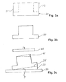
- the T-shaped side part 2, 3 is made from a glass blank 20 with an I-shaped one Cross section (Fig. 3a) made, the length of which corresponds to the length of the hollow mixing rod 1 is selected.
- the side regions 21, 22 are removed from this glass blank 20 (for example by grinding) so that the T-shaped cross section shown in Fig. 3b is formed.
- the angle ⁇ is chosen so that it corresponds to the angle 90 ° - ⁇ .
- the angle ⁇ is thus 7 °.
- the crossbar of the T-shaped glass blank 20 facing away from the end surface of the central web 10 is then by means of a grinding wheel 26 ground until the end face 15 (shown as a broken line in Fig. 3c) with the desired Inclination towards the side surfaces of the central web is formed.
- This end surface 15 is then still polished and mirrored. In this way, any desired angle of inclination can be very easily End surface 15 are formed relative to the side surfaces 11, 12 of the central web 10. That’s it first and second side parts 2, 3 completed.
- the carrier plate 24 and the wedge 23 can also be a Be a tool.
- the third and fourth side part 4, 5 is also formed from an I-shaped blank, the latter being Inside, which, in the assembled state of the hollow mixing rod 1, delimits the cavity 6, is polished and mirrored.
- the four side parts 2 to 5 thus formed are then in accordance with the structure shown in FIGS. 1 and 2 composed.
- the shrink tube 19 is slipped over, the inside cross section is larger than the outer cross section of the hollow mixing rod 1, so that it is easy to slip on.
- the shrink tube 19 is heated so that it contracts and thereby the four Side parts 2 to 5 press against each other and fixed.
- the shrink tube 19 keeps this contracted shape even after cooling, so that the side parts 2 to 5 permanently are pressed against each other and are thus permanently fixed.
- This optical device comprises a light source 27 and the hollow mixing rod 1 connected downstream thereof, in the one facing the light source 27 Light entry surface 7 light from the light source 1 is coupled, which is then in the hollow mixing rod 1 to Light exit surface 8 is directed.
- the optical device further contains one of the light exit surface 8 of the hollow mixing rod 1 downstream intermediate optics 28, with which the from the light exit surface 8th emerging light is directed onto an imaging element 29 so that it is as possible is evenly illuminated.
- An imaging element 29 can be, for example Tilting mirror matrix or an LCD matrix can be used.
- the imaging element 29 is by means of a control unit (not shown) driven on the basis of predetermined image data, so that the desired image can be set, which is then by means of projection optics 30 Optical device is projected on a projection surface 31.
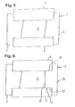
- FIG. 5 A further embodiment of the hollow mixing rod 1 can be seen in FIG. 5.
- This embodiment differs from the embodiment shown in Fig. 2 in that the first side part 2 so Is rotated 180 ° that the cavity 6 has a parallelogram cross section.
- the first and second side parts 2, 3 have the same cross-sectional shape, so that advantageously only one Kind of T-shaped side parts with an inclined end face 15 must be produced.
- the first and second side parts 2, 3, the inclination of the end face 15 is different great to choose. In this case, two different types of side parts have to be produced become.
- FIG. 6 A further embodiment is shown in FIG. 6, in which compared to that in FIGS. 1 and 2 shown embodiment, a T-shaped side part 32 is provided instead of the first side part 2, the end surface 33 of the central web 34 perpendicular to the side surfaces 35, 36 of the central web 34 runs.
Abstract
Bei einem Herstellungsverfahren für einen Hohlmischstab (1), der einen Hohlraum (6) mit viereckigem Querschnitt aufweist, werden folgenden Schritte ausgeführt: Fertigen eines ersten und eines zweiten Seitenteiles (2, 3), das jeweils einen T-förmigen Querschnitt mit einem Quersteg (9) und einem davon vorspringenden Mittelsteg (10) aufweist, der eine dem Quersteg (9) abgewandte, reflektierende Endfläche (15) und im Querschnitt gesehen eine erste und eine zweite von der Endfläche (15) zum Quersteg (9) verlaufende Seitenfläche (11, 12) umfaßt, wobei zumindest beim ersten Seitenteil (2) die Endfläche (15) und die erste Seitenfläche (11) im Querschnitt gesehen unter einem Winkel (α) zusammenlaufen, der ungleich 90° ist, Fertigen eines dritten und vierten Seitenteiles (4, 5) mit jeweils einer reflektierenden, ebenen Innenseite (16), Zusammensetzen der vier Seitenteile (2, 3, 4, 5) derart, daß die Endflächen (15) des ersten und zweiten Seitenteiles (2, 3) einander zugewandt sind und daß die reflektierenden Innenseiten (16) des dritten und vierten Seitenteils (4, 5) im Querschnitt gesehen zueinander parallel verlaufen und mit ihren Randabschnitten auf den Seitenflächen (11, 12) der Mittelstege (10) aufliegen, so daß der Hohlraum (6) mit viereckigem Querschnitt begrenzt wird. <IMAGE>The following steps are carried out in a manufacturing method for a hollow mixing rod (1) which has a cavity (6) with a square cross section: Manufacture of a first and a second side part (2, 3), each of which has a T-shaped cross section with a transverse web ( 9) and a central web (10) projecting therefrom, which has a reflective end surface (15) facing away from the cross web (9) and, viewed in cross section, a first and a second side surface (11) running from the end surface (15) to the cross web (9) , 12), wherein at least in the first side part (2) the end face (15) and the first side face (11) seen in cross section converge at an angle (α) which is not equal to 90 °, producing a third and fourth side part (4th , 5) each with a reflective, flat inside (16), assembling the four side parts (2, 3, 4, 5) such that the end faces (15) of the first and second side parts (2, 3) face each other and nd that the reflecting inner sides (16) of the third and fourth side parts (4, 5), seen in cross section, run parallel to one another and rest with their edge sections on the side surfaces (11, 12) of the central webs (10), so that the cavity (6) is limited with a square cross-section. <IMAGE>
Description
Die Erfindung bezieht sich auf ein Herstellungsverfahren für einen Hohlmischstab und auf einen Hohlmischstab mit vier Seitenteilen mit jeweils einer reflektierenden Innenseite, die jeweils eine Seite eines sich von einer Lichteintrittsfläche bis zu einer Lichtaustrittsfläche erstreckenden Hohlraumes mit viereckigem Querschnitt bildet.The invention relates to a manufacturing method for a hollow mixing rod and to one Hollow mixing rod with four side parts, each with a reflective inside, one side each a cavity extending from a light entry surface to a light exit surface forms a square cross section.
Bei einem solchen Hohlmischstab kommt es für seine Eigenschaften sehr darauf an, daß die reflektierenden Innenseiten der vier Seitenteile so zusammengefügt sind, daß keinerlei Spalt zwischen ihnen gebildet ist, an dem es zu Lichtverlusten kommen würde. Insbesondere wenn die viereckige Querschnittsform des Hohlraumes nicht rechteckig oder quadratisch ist und somit seine Querschnittsseiten an zumindest einer Ecke unter einem Winkel zusammenlaufen, der ungleich 90° ist, ist die Herstellung eines solchen Hohlmischstabes sehr aufwendig.In such a hollow mixing rod, it is very important for its properties that the reflective insides of the four side parts are assembled so that no gap between is formed, which would lead to loss of light. Especially if the square Cross-sectional shape of the cavity is not rectangular or square and thus its Cross-sectional sides converge at at least one corner at an angle that is not equal to 90 °, the production of such a hollow mixing rod is very complex.
Ausgehend hiervon ist es Aufgabe der Erfindung, ein Herstellungsverfahren für einen Hohlmischstab bereitzustellen, mit dem der Hohlmischstab einfach und genau hergestellt werden kann, auch wenn zwei Querschnittsseiten des Hohlraumes unter einem Winkel zusammenlaufen, der ungleich 90° ist. Femer soll noch ein Hohlmischstab der eingangs genannten Art so verbessert werden, daß er möglichst leicht herstellbar ist.Proceeding from this, it is an object of the invention to provide a manufacturing method for a hollow mixing rod To provide with the hollow mixing rod can be easily and accurately manufactured, even if two cross-sectional sides of the cavity converge at an angle that is not equal to 90 °. Furthermore, a hollow mixing rod of the type mentioned should be improved so that it is as easy to manufacture as possible.
Erfindungsgemäß wird diese Aufgabe durch das Herstellungsverfahren für einen Hohlmischstab, der einen Hohlraum mit viereckigen Querschnitt aufweist, mit folgenden Schritten gelöst: Fertigen eines ersten und eines zweiten Seitenteiles, das jeweils einen T-förmigen Querschnitt mit einem Quersteg und einem davon vorspringenden Mittelsteg aufweist, der eine dem Quersteg abgewandte, reflektierende Endfläche und im Querschnitt gesehen eine erste und eine zweite von der Endfläche zum Quersteg verlaufende Seitenfläche umfaßt, wobei zumindest beim ersten Seitenteil die Endfläche und die erste Seitenfläche im Querschnitt gesehen unter einem Winkel zusammenlaufen, der ungleich 90° ist, Fertigen eines dritten und vierten Seitenteiles mit jeweils einer reflektierenden, ebenen Innenseite, Zusammensetzen der vier Seitenteile derart, daß die Endfläche des ersten und zweiten Seitenteiles einander zugewandt sind und daß die reflektierenden Innenseiten des dritten und vierten Seitenteiles im Querschnitt gesehen zueinander parallel verlaufen und mit ihren Randabschnitten auf den Seitenflächen der Querstege aufliegen, so daß der Hohlraum unter Ausbildung des viereckigen Querschnitts begrenzt wird. Durch dieses Verfahren muß lediglich bei einem Seitenteil mit T-förmigen Querschnitt die Endfläche schräg zu den Seitenflächen gebildet werden. Ein solches Abschrägen der Endfläche ist besonders einfach und genau durch Abschleifen eines T-förmigen Rohlings möglich, bei dem die Endfläche senkrecht zu den Seitenflächen verläuft. Ein solches Schleifen der Endfläche kann einerseits mit hoher Genauigkeit und Präzision durchgeführt werden. Andererseits kann man dieses Schleifen auch für eine Mehrzahl von Seitenteilen gleichzeitig durchführen, so daß auch eine Produktion hoher Stückzahlen mit unverändert hoher Genauigkeit durchführbar ist.According to the invention, this object is achieved by the production method for a hollow mixing rod has a cavity with a square cross section, solved with the following steps: manufacture one first and a second side part, each of a T-shaped cross section with a crossbar and has a central web projecting therefrom, which has a central web facing away from the transverse web, reflective end face and seen in cross section a first and a second from the end face includes the side surface extending to the crosspiece, the end surface at least in the first side part and the first side surface seen in cross section converge at an angle that is not equal 90 °, manufacture a third and fourth side part, each with a reflective, flat Inside, assembling the four side panels so that the end face of the first and second Side part facing each other and that the reflective insides of the third and fourth Side part seen in cross section run parallel to each other and with their edge sections rest on the side surfaces of the crossbars, so that the cavity to form the square Cross-section is limited. This procedure only requires a T-shaped side panel Cross section of the end surface are formed obliquely to the side surfaces. Such a beveling of the End surface is particularly simple and accurate by grinding a T-shaped blank, at whose end face is perpendicular to the side faces. Such grinding of the end face can on the one hand with high accuracy and precision. On the other hand, you can do this Carry out grinding for a plurality of side parts simultaneously, so that one Production of large quantities with unchanged high accuracy is feasible.
Um die gewünschte Ebenheit der Endflächen zu erhalten, werden bevorzugt die Endflächen nach dem Schleifen noch poliert.In order to obtain the desired flatness of the end faces, the end faces after the Grinding still polished.
Falls es sich beim dem Material des T-förmigen Rohlings um ein Material handelt, das keine ausreichenden reflektierenden Eigenschaften aufweist, kann die geschliffene und gegebenenfalls polierte Endfläche noch verspiegelt werden. Dies kann man beispielsweise durch Verspiegelung mit einer Silberschicht oder durch Aufbringen einer dielektrischen Verspiegelungsschicht realisieren. Je nach Art der Spiegelschicht kann gegebenenfalls noch eine Schutzschicht auf die Spiegelschicht aufgebracht werden.If the material of the T-shaped blank is a material that is not has sufficient reflective properties, the ground and optionally polished end surface can still be mirrored. You can do this, for example, by mirroring with a silver layer or by applying a dielectric reflecting layer. ever Depending on the type of mirror layer, a protective layer can optionally be applied to the mirror layer be applied.
Die Endfläche kann statt mittels Schleifen auch durch Fräsen gebildet werden, wobei bevorzugt die Endfläche noch poliert wird.The end surface can also be formed by milling instead of grinding, preferably the End surface is still polished.
Die Seitenteile können aus Glas, Metall, Metallegierungen, Keramik oder Kunststoff gefertigt werden. Wenn Kunststoff verwendet wird, können das erste und zweite Seitenteil beispielsweise durch Spritzgießen gleich mit der abgeschrägten Endfläche gebildet werden. Die Endfläche kann bevorzugt noch nachbearbeitet werden, wenn die Ebenheit der Endfläche verbessert werden soll. Auch hier kann die Endfläche verspiegelt werden. Wenn Metall oder eine Metallegierung eingesetzt wird, kann die reflektierende Eigenschaft der Endfläche nur durch Polieren erzeugt werden. Auch bei diesen Materialien können die Seitenteile schon mit abgeschrägten Endflächen z. B. durch Gießverfahren gebildet werden. Alternativ ist natürlich auch ein Abschleifen oder Fräsen zur Abschrägung der Endfläche möglich.The side parts can be made of glass, metal, metal alloys, ceramic or plastic. If plastic is used, the first and second side part can be made, for example, by Injection molding can be formed with the tapered end surface. The end face may be preferred still be reworked if the flatness of the end surface is to be improved. Here too the end face will be mirrored. If metal or a metal alloy is used, the reflective property of the end surface can only be produced by polishing. Even with these Materials can already have the side parts with beveled end surfaces such. B. by casting process be formed. Alternatively, of course, is also grinding or milling to chamfer the End surface possible.
In einer vorteilhaften Weiterbildung des erfindungsgemäßen Herstellungsverfahrens wird nach dem Zusammensetzen der vier Seitenteile ein Schrumpfschlauch über die vier Seitenteile übergezogen, der danach erwärmt wird. Aufgrund der Erwärmung schrumpft der Schlauch bzw. zieht sich zusammen und drückt dadurch die vier Seitenteile gegeneinander. Da der Schrumpfschlauch seine zusammengezogene Form nach dem Abkühlen beibehält, wird eine dauerhafte Fixierung der Seitenteile erreicht. Der Schrumpfschlauch kann im Mittelbereich des Hohlmischstabes in Längsrichtung gesehen angeordnet sein. Alternativ können auch zwei Schrumpfschläuche jeweils an den Endabschnitten des Hohlmischstabes in Längsrichtung gesehen vorgesehen werden. Die Verwendung des Schrumpfschlauches führt zu einer sehr einfachen und effektiven Art der Fixierung der vier Seitenteile relativ zueinander, die leicht und unproblematisch durchführbar ist. Insbesondere das Gegeneinanderdrücken der vier Seitenteile mittels des Schrumpfschlauches führt dazu, daß keinerlei Spalte zwischen den verspiegelten bzw. reflektierenden Innenseiten auftreten, so daß der Hohlmischstab mit der erforderlichen hohen Genauigkeit in einfacher Art und Weise gefertigt werden kann.In an advantageous development of the manufacturing method according to the invention, according to the Assembling the four side parts, a heat shrink tube pulled over the four side parts, the is then heated. Due to the heating, the hose shrinks or contracts and thereby pushes the four side parts against each other. Because the shrink tube is his retracted shape after cooling, permanent fixation of the Side parts reached. The shrink tube can be in the middle area of the hollow mixing rod Seen in the longitudinal direction. Alternatively, two shrink sleeves can be attached the end portions of the hollow mixing rod can be provided seen in the longitudinal direction. The Using the shrink tube leads to a very simple and effective way of fixing of the four side parts relative to one another, which can be carried out easily and without problems. In particular pressing the four side parts against one another by means of the shrink tube leads to the fact that no gaps between the mirrored or reflective insides occur, so that the Hollow mixing rod can be manufactured with the required high accuracy in a simple manner can.
Der erfindungsgemäße Hohlmischstab mit den vier Seitenteilen mit jeweils einer ebenen, reflektierenden. Innenseite, die jeweils eine Seite eines sich von einer Lichteintrittsfläche bis zu einer Lichtaustrittsfläche erstreckenden Hohlraumes mit viereckigem Querschnitt bildet, ist dadurch gekennzeichnet, daß das erste und zweite Seitenteil jeweils einen T-förmigen Querschnitt mit einem Quersteg und einem davon vorspringenden Mittelsteg aufweist, dessen dem Quersteg abgewandte Endfläche die reflektierende Innenseite des Seitenteiles bildet und im Querschnitt gesehen eine erste und eine zweite von der Endfläche zum Quersteg verlaufende Seitenfläche umfaßt, wobei die reflektierenden Innenseiten des dritten und vierten Seitenteiles im Querschnitt gesehen zueinander parallel angeordnet sind und mit ihren Randabschnitten auf den Seitenflächen der Querstege aufliegen, wobei zumindest beim ersten Seitenteil die Endfläche und die erste Seitenfläche im Querschnitt gesehen unter einem Winkel zusammenlaufen, der ungleich 90° ist. Der erfindungsgemäße Hohlmischstab ist somit besonders leicht herstellbar, da zum Bilden einer Querschnittsform des Hohlraums, bei der in einer Ecke zwei Seiten unter einem Winkel zusammenlaufen, der ungleich 90° ist, z. B. lediglich die Endfläche des ersten Seitenteiles schräg abgeschliffen werden muß. Dies ist mit der erforderlichen hohen Genauigkeit leicht und einfach möglich. Das erste Seitenteil umfaßt somit bevorzugt eine schräg geschliffene Endfläche auf. Die Endfläche des Mittelsteges legt also den Winkel, unter dem die zwei Querschnittsseiten zusammenlaufen und der ungleich 90° ist, fest. Ferner liegen die Innenseiten des dritten und vierten Seitenteiles mit ihren Randabschnitten auf den Seitenflächen der Mittelstege auf, so daß die Mittelstege des ersten und zweiten Seitenteiles auch noch dazu dienen, den Abstand der reflektierenden Innenflächen des dritten und vierten Seitenteils vorzugeben und beizubehalten.The hollow mixing rod according to the invention with the four side parts, each with a flat, reflective. Inside, one side each from a light entry surface to one This forms the light exit surface extending cavity with a square cross section characterized in that the first and second side part each have a T-shaped cross section with a Crossbar and a projecting central web, the opposite of the crossbar End surface forms the reflective inside of the side part and seen in cross section a first and a second side surface extending from the end surface to the crossbar, the reflective inner sides of the third and fourth side part seen in cross section to each other are arranged in parallel and with their edge sections on the side surfaces of the crossbars rest, at least in the first side part, the end surface and the first side surface in Seen cross section converge at an angle that is not equal to 90 °. The The hollow mixing rod according to the invention is thus particularly easy to produce, since it forms a Cross-sectional shape of the cavity, with two sides at an angle in a corner converge, which is not equal to 90 °, z. B. only the end face of the first side part obliquely must be ground down. This is easy and simple with the required high accuracy possible. The first side part thus preferably has an obliquely ground end surface. The The end face of the center bar therefore defines the angle at which the two cross-sectional sides converge and which is not 90 °, solid. Furthermore, the inside of the third and fourth Side part with its edge sections on the side surfaces of the central webs, so that the Center bars of the first and second side panels also serve to distance the specify and maintain reflective inner surfaces of the third and fourth side part.
In einer vorteilhaften Weiterbildung des erfindungsgemäßen Hohlmischstabes werden die vier Seitenteile durch einen Schrumpfschlauch zusammengehalten. Die Verwendung eines Schrumpfschlauches zum Zusammenhalten und Fixeren der vier Seitenteile führt zu einer vereinfachten Herstellung des Hohlmischstabes, da der Schrumpfschlauch nur über die vier Seitenteile übergestülpt und danach erwärmt werden muß. Die Fixierung und Ausrichtung der vier Seitenteile erfolgt dann quasi automatisch, da sich der zusammenziehende Schrumpfschlauch an die Außenform der vier Seitenteile anpaßt und diese gegeneinander drückt. Bei diesem gegeneinander Drücken werden das dritte und vierte Seitenteil mit ihren reflektierenden Innenflächen auf den Seitenflächen der Mittelstege geführt und schließlich mit ihren Längsseiten gegen die Querstege gedrückt. Mit dem Schrumpfschlauch wird auch verhindert, daß der Hohlmischstab Spalte zwischen den reflektierenden Innenseiten aufweist, so daß die reflektierenden Flächen lichtdicht aneinanderliegen.In an advantageous development of the hollow mixing rod according to the invention, the four Side parts held together by a shrink tube. The use of a Shrink tube to hold together and fix the four side parts leads to one Simplified manufacture of the hollow mixing rod because the shrink tube only over the four side parts put on and then warmed up. The fixation and alignment of the four side parts is then done almost automatically, because the contracting shrink tube attaches to the outer shape who adjusts the four side parts and presses them against each other. In this press against each other the third and fourth side panels with their reflective inner surfaces on the side surfaces of the Guided middle bars and finally pressed with their long sides against the cross bars. With the Shrink tubing is also prevented from the hollow mixing rod between the reflective Has insides so that the reflective surfaces lie light-tight against each other.
Vorteilhaft kann bei dem erfindungsgemäßen Hohlmischstab beim zweiten Seitenteil die Endfläche und die erste Seitenfläche im Querschnitt gesehen auch unter einem Winkel zusammenlaufen, der ungleich 90° ist. Dadurch wird es möglich, eine symmetrische Querschnittsform des Hohlraums, wie zum Beispiel einen trapezförmigen Querschnitt, zu verwirklichen. Man kann jedoch auch parallelogrammförmige Querschnittformen oder auch Querschnittsformen realisieren, bei denen die Querschnittseiten in den vier Ecken unter jeweils einem anderen Winkel zusammenlaufen.In the case of the hollow mixing rod according to the invention, the end face and the first side surface seen in cross section also converge at an angle that is not equal to 90 °. This makes it possible to have a symmetrical cross-sectional shape of the cavity, such as for example a trapezoidal cross-section. But you can also Realize parallelogram-shaped cross-sectional shapes or cross-sectional shapes in which the Cross-sectional sides converge at a different angle in the four corners.
Insbesondere kann bei dem erfindungsgemäßen Hohlmischstab das dritte und vierte Seitenteil jeweils einen I-förmigen Querschnitt aufweisen, wobei das dritte und vierte Seitenteil mit seinen Längsseiten an den Querstegen des ersten und zweiten Seitenteiles anliegt. Damit wird ein sehr kompakter Hohlmischstab verwirklicht, der stabil aufgebaut ist.In particular, in the case of the hollow mixing rod according to the invention, the third and fourth side parts in each case have an I-shaped cross section, the third and fourth side part with its long sides abuts the crossbars of the first and second side part. This makes it a very compact one Hollow mixing rod realized, which is stable.
Der erfindungsgemäße Hohlmischstab kann insbesondere bei einer Optikvorrichtung zum Erzeugen und Projizieren eines Bildes verwendet werden. Die Optikvorrichtung enthält bevorzugt eine Lichtquelle, ein bilderzeugendes Element und eine Projektionsoptik, wobei der Hohlmischstab zwischen Lichtquelle und bilderzeugendem Element zwischengeschaltet ist. Das Licht der Lichtquelle wird über die Lichteintrittsfläche in den Hohlmischstab eingekoppelt und im Hohlmischstab bis zur Lichtaustrittsfläche geführt. Dabei werden die Lichtstrahlen, die auf die reflektierenden Innenseiten treffen, durch eine oder mehrerer Reflexionen bis zur Lichtaustrittsfläche geführt. Dies führt dazu, daß die Leuchtdichteverteilung in der Lichtaustrittsfläche im Vergleich zu der in der Lichteintrittsfläche gleichmäßiger ist, so daß in der Lichtaustrittsfläche ein möglichst gleichmäßig leuchtendes Feld erzeugt wird. Dieses leuchtende Feld wird zum Beispiel unter Zwischenschaltung einer Zwischenoptik auf das bildgebende Element abgebildet, um dieses möglichst gleichmäßig auszuleuchten. Das bildgebende Element wird aufgrund vorgegebener Bilddaten mittels einer Ansteuereinheit angesteuert, um das Bild zu erzeugen, das mittels der Projektionsoptik auf eine Projektionsfläche projiziert wird.The hollow mixing rod according to the invention can be produced in particular in an optical device and projecting an image. The optical device preferably contains one Light source, an imaging element and a projection optics, the hollow mixing rod is interposed between the light source and the imaging element. The light from the light source is coupled into the hollow mixing rod via the light entry surface and in the hollow mixing rod up to Led light exit surface. In doing so, the light rays are reflected on the reflective inner sides meet, led through one or more reflections to the light exit surface. This leads to the luminance distribution in the light exit area compared to that in the light entry area is more uniform, so that a field that shines as uniformly as possible in the light exit surface is produced. This luminous field is interposed, for example, with an intermediate optic mapped onto the imaging element in order to illuminate it as evenly as possible. The imaging element is controlled on the basis of predetermined image data by means of a control unit, to generate the image that is projected onto a projection surface using the projection optics.
Die Erfindung wird nachfolgend anhand der Zeichnungen im Prinzip beispielshalber noch näher erläutert. Es zeigen:
- Fig. 1
- eine perspektivische Ansicht des erfindungsgemäßen Hohlmischstabes;
- Fig. 2
- eine Vorderansicht des in Fig. 1 gezeigten Hohlmischstabes;
- Fig. 3a - 3c
- Herstellungsschritte zum Fertigen des T-förmigen Seitenteiles;
- Fig. 4
- eine prinzipielle Draufsicht einer Optikvorrichtung mit dem erfindungsgemäßen Lichtmischstab;
- Fig. 5
- eine Vorderansicht eines erfindungsgemäßen Lichtmischstabes gemäß einer weiteren Ausführungsform, und
- Fig. 6
- eine Vorderansicht eines erfindungsgemäßen Lichtmischstabes gemäß einer noch weiteren Ausführungsform.
- Fig. 1
- a perspective view of the hollow mixing rod according to the invention;
- Fig. 2
- a front view of the hollow mixing rod shown in Fig. 1;
- 3a-3c
- Manufacturing steps for manufacturing the T-shaped side part;
- Fig. 4
- a basic plan view of an optical device with the light mixing rod according to the invention;
- Fig. 5
- a front view of a light mixing rod according to the invention according to a further embodiment, and
- Fig. 6
- a front view of a light mixing rod according to the invention according to yet another embodiment.
Wie aus Fig. 1 und 2 (in Fig. 2 ist der in Fig. 1 gezeigte Schrumpfschlauch 19 nicht eingezeichnet)
ersichtlich ist, umfaßt der Hohlmischstab 1 vier Seitenteile 2, 3, 4 und 5, die einen Hohlraum 6 mit
trapezförmigen Querschnitt bilden, wobei die in Längsrichtung des Hohlmischstabes 1 gesehen beide
Enden offen sind und eine trapezförmige Lichteintrittsfläche 7 und eine trapezförmige
Lichtaustrittsfläche 8 bilden.As in FIGS. 1 and 2 (the
Wie insbesondere aus Fig. 2 ersichtlich ist, ist der Hohlmischstab 1 bezüglich einer in einer
Querschnittsebene liegenden Mittelachse A symmetrisch ausgebildet, so daß jeweils das erste und
zweite Seitenteil 2, 3 und das dritte und vierte Seitenteil 4, 5 den gleichen Aufbau aufweisen. Im
folgenden wird daher nur der Aufbau des zweiten und dritten Seitenteiles 3, 4 im Detail beschrieben.As can be seen in particular from FIG. 2, the
Das zweite Seitenteil 3 weist einen T-förmigen Querschnitt mit einem Quersteg 9 und einem davon
mittig vorspringen Mittelsteg 10 auf. Der Mittelsteg 10 erstreckt sich senkrecht zum Quersteg 9, so daß
die Seitenflächen 11, 12 des Mittelstegs 10 senkrecht zu den Grundflächen 13, 14 des Querstegs 9
verlaufen. Die dem Quersteg 9 abgewandte ebene Endfläche 15 des Mittelstegs 10 verbindet die
beiden Seitenflächen 11, 12 miteinander und läuft mit der Seitenfläche 11 unter einem Winkel α
zusammen, der kleiner als 90° ist. In dem hier gezeigten Ausführungsbeispiel beträgt der Winkel 83°.
Die Endfläche 15, die eine Seite des Hohlraums 6 begrenzt, ist reflektierend ausgebildet. Bei der hier
beschriebenen Ausführungsform ist das zweite Seitenteil 3 aus Glas gebildet und die Endfläche 15 ist
mit einer Spiegelschicht aus beispielsweise Silber oder mit einer dielektrischen Spiegelschicht
versehen.The
Das dritte Seitenteil 4 weist einen I-förmigen Querschnitt mit einer reflektierenden Innenseite 16 auf.
Auch das dritte Seitenteil 4 ist aus Glas gebildet und die reflektierende Innenseite 16 ist wiederum
verspiegelt, zum Beispiel mit einer Silberschicht oder einer dielektrischen Spiegelschicht. Die Form des
dritten Seitenteiles 4 ist so gewählt, daß ihre Längsseiten 17, 18 senkrecht zur reflektierenden
Innenseite 16 verlaufen. The
Das erste und zweite Seitenteil 2, 3 sind mit einem vorbestimmten Abstand voneinander angeordnet,
wobei die beiden Endflächen 15 einander zugewandt sind, und bilden das rechte und linke Seitenteil
des Hohlmischstabes 1. Das obere und untere Seitenteil des Hohlmischstabes 1 wird durch das dritte
und vierte Seitenteil 4, 5 verwirklicht, wobei das dritte Seitenteil 4 mit seinen beiden seitlichen
Randbereichen auf den Seitenflächen 11 der Mittelstege 10 aufliegt und das vierte Seitenteil 5 mit
seinen beiden seitlichen Randbereichen auf den Seitenflächen 12 der Mittelstege 10 aufliegt, so daß
die reflektierenden Innenseiten 16 des dritten und vierten Seitenteiles 4, 5 im Querschnitt gesehen
zueinander parallel verlaufen. Die vier Seitenteile 2 bis 5 werden durch einen über den Hohlmischstab
1 übergestülpten Schrumpfschlauch 19 (der nur in Fig. 1 eingezeichnet ist) gegeneinander gedrückt
und fixiert. Dabei werden einerseits die Grundflächen 13, 14 der Querstege 9 des ersten und zweiten
Seitenteiles 2, 3 gegen die Längsseiten 17, 18 des dritten und vierten Seitenteiles 4, 5 gedrückt und
andererseits werden die reflektierenden Innenseiten 16 des dritten und vierten Seitenteils 4, 5 in ihren
im Querschnitt gesehenen seitlichen Randbereichen bzw. -abschnitten gegen die Seitenflächen 11, 12
der Mittelstege 10 des ersten und zweiten Seitenteils 2, 3 gedrückt. Dadurch wird ein sehr kompakter
und stabiler Hohlmischstab 1 bereitgestellt, der leicht zu fertigen und zu montieren ist und der den
Hohlraum 6 mit einer viereckigen Querschnittsform aufweist, bei der die Querschnittsseiten in den vier
Ecken jeweils unter einem Winkel zusammenlaufen, der ungleich 90° ist.The first and
Im folgenden wird ein erfindungsgemäßes Verfahren zum Herstellen des in Fig. 1 und 2 gezeigten
Hohlmischstabes 1 beschrieben. Das T-förmige Seitenteil 2, 3 wird aus einem Glasrohling 20 mit I-förmigen
Querschnitt (Fig. 3a) gefertigt, dessen Länge entsprechend der Länge des Hohlmischstabes
1 gewählt ist. Von diesem Glasrohling 20 werden die Seitenbereiche 21, 22 entfernt (beispielsweise
durch Schleifen), so daß der in Fig. 3b gezeigte T-förmige Querschnitt gebildet ist. Danach wird dieser
T-förmige Glasrohling auf einem Keil 23 einer Trägerplatte 24 befestigt, wobei die Keilfläche 25, auf
der der T-förmige Glasrohling 20 aufliegt, gegenüber der Trägerplatte 24 um den Winkel β geneigt ist.
Der Winkel β ist dabei so gewählt, daß er gleich dem Winkel 90° - α entspricht. In dem hier
beschriebenen Beispiel beträgt der Winkel β somit 7°. Die dem Quersteg des T-förmigen Glasrohlings
20 abgewandte Endfläche des Mittelstegs 10 wird dann mittels einer Schleifscheibe 26 so lange
geschliffen, bis die Endfläche 15 (ist in Fig. 3c als Strichlinie eingezeichnet) mit der gewünschten
Neigung gegenüber den Seitenflächen des Mittelstegs gebildet ist. Diese Endfläche 15 wird dann noch
poliert und verspiegelt. Auf diese Weise kann sehr einfach jeder gewünschte Neigungswinkel der
Endfläche 15 relativ zu den Seitenflächen 11, 12 des Mittelstegs 10 gebildet werden. Damit ist das
erste und zweite Seitenteil 2, 3 fertiggestellt. Die Trägerplatte 24 und der Keil 23 können auch ein
Werkzeug sein.The following is a method according to the invention for producing that shown in FIGS. 1 and 2
Das dritte und vierte Seitenteil 4, 5 wird auch aus einem I-förmigen Rohling gebildet, wobei dessen
Innenseite, die im zusammengebauten Zustand des Hohlmischstabes 1 den Hohlraum 6 begrenzt,
poliert und verspiegelt wird. The third and
Die so gebildeten vier Seitenteile 2 bis 5 werden dann gemäß dem in Fig. 1 und 2 gezeigten Aufbau
zusammengesetzt. Danach wird der Schrumpfschlauch 19 übergestülpt, dessen Innenquerschnitt
größer ist als der Außenquerschnitt des Hohlmischstabes 1, so daß das Überstülpen leicht möglich ist.
Dann wird der Schrumpfschlauch 19 erwärmt, so daß er sich zusammenzieht und dadurch die vier
Seitenteile 2 bis 5 aneinander drückt und fixiert. Der Schrumpfschlauch 19 behält diese
zusammengezogene Form auch nach dem Abkühlen bei, so daß die Seitenteile 2 bis 5 dauerhaft
gegeneinander gedrückt werden und somit auch dauerhaft fixiert sind.The four
In Fig. 4 ist die Verwendung des erfindungsgemäßen Hohlmischstabes 1 in einer Optikvorrichtung zum
Erzeugen und Projizieren eines Bildes gezeigt. Diese Optikvorrichtung umfaßt eine Lichtquelle 27 und
den dieser nachgeschalteten Hohlmischstab 1, in dessen der Lichtquelle 27 zugewandten
Lichteintrittsfläche 7 Licht der Lichtquelle 1 eingekoppelt wird, das dann im Hohlmischstab 1 bis zur
Lichtaustrittsfläche 8 geleitet wird. Die Optikvorrichtung enthält weiterhin eine der Lichtaustrittsfläche 8
des Hohlmischstabes 1 nachgeschaltete Zwischenoptik 28, mit der das aus der Lichtaustrittsfläche 8
austretende Licht auf ein bildgebendes Element 29 so gerichtet wird, daß dieses möglichst
gleichmäßig ausgeleuchtet wird. Als bildgebendes Element 29 kann beispielsweise eine
Kippspiegelmatrix oder eine LCD-Matrix verwendet werden. Das bildgebende Element 29 wird mittels
einer Ansteuereinheit (nicht gezeigt) auf der Basis vorgegebener Bilddaten angesteuert, so daß das
gewünschte Bild eingestellt werden kann, das dann mittels einer Projektionsoptik 30 der
Optikvorrichtung auf einer Projektionsfläche 31 projiziert wird.4 shows the use of the
In Fig. 5 ist eine weitere Ausführungsform des Hohlmischstabes 1 zu sehen. Diese Ausführungsform
unterscheidet sich von der in Fig. 2 gezeigten Ausführungsform darin, daß das erste Seitenteil 2 so um
180° gedreht ist, daß der Hohlraum 6 einen Parallelogramm-Querschnitt aufweist. Bei dieser
Ausführungsform und auch bei der in Fig. 1 und 2 gezeigten Ausführungsform des Hohlmischstabes 1
weist das erste und zweite Seitenteil 2, 3 die gleich Querschnittsform auf, so daß vorteilhaft nur eine
Art von T-förmigen Seitenteilen mit schräger Endfläche 15 hergestellt werden muß. Es ist jedoch auch
möglich, beim ersten und zweiten Seitenteil 2, 3 jeweils die Neigung der Endfläche 15 unterschiedlich
groß zu wählen. In diesem Fall müssen dann zwei verschiedene Arten von Seitenteilen hergestellt
werden.A further embodiment of the
In Fig. 6 ist eine noch weitere Ausführungsform gezeigt, bei der im Vergleich zu der in Fig. 1 und 2
gezeigten Ausführungsform statt dem ersten Seitenteil 2 ein T-förmiges Seitenteil 32 vorgesehen ist,
dessen Endfläche 33 des Mittelstegs 34 senkrecht zu den Seitenflächen 35, 36 des Mittelstegs 34
verläuft.A further embodiment is shown in FIG. 6, in which compared to that in FIGS. 1 and 2
shown embodiment, a T-shaped
Claims (8)
Applications Claiming Priority (2)
| Application Number | Priority Date | Filing Date | Title |
|---|---|---|---|
| DE10109591A DE10109591A1 (en) | 2001-02-28 | 2001-02-28 | Manufacturing process for a hollow mixing rod and hollow mixing rod |
| DE10109591 | 2001-02-28 |
Publications (2)
| Publication Number | Publication Date |
|---|---|
| EP1237033A2 true EP1237033A2 (en) | 2002-09-04 |
| EP1237033A3 EP1237033A3 (en) | 2003-09-17 |
Family
ID=7675773
Family Applications (1)
| Application Number | Title | Priority Date | Filing Date |
|---|---|---|---|
| EP01130317A Withdrawn EP1237033A3 (en) | 2001-02-28 | 2001-12-19 | Hollow light-mixing rod and manufacturing method for the same |
Country Status (3)
| Country | Link |
|---|---|
| US (1) | US6625380B2 (en) |
| EP (1) | EP1237033A3 (en) |
| DE (1) | DE10109591A1 (en) |
Families Citing this family (16)
| Publication number | Priority date | Publication date | Assignee | Title |
|---|---|---|---|---|
| TW523120U (en) * | 2002-06-26 | 2003-03-01 | Young Optics Inc | Assembling structure of hollow integration post |
| JP4018949B2 (en) * | 2002-07-29 | 2007-12-05 | フジノン株式会社 | Manufacturing method of rod integrator |
| US7169252B2 (en) * | 2003-07-11 | 2007-01-30 | Oc Oerlikon Balzers Ag | Method for the assembly of light integrators |
| US20050135761A1 (en) * | 2003-12-23 | 2005-06-23 | Cannon Bruce L. | Optical element for uniform illumination and optical system incorporating same |
| TW200532351A (en) * | 2004-03-29 | 2005-10-01 | Coretronic Corp | Mounting structure for hollow integration rod |
| US20050244126A1 (en) * | 2004-04-30 | 2005-11-03 | Hewlett-Packard Co. | Light guides and method of forming same |
| TWI264608B (en) * | 2005-04-08 | 2006-10-21 | Delta Electronics Inc | Light tunnel module |
| TWI312905B (en) * | 2005-04-28 | 2009-08-01 | Delta Electronics Inc | Light tunnel |
| US7438423B2 (en) * | 2005-08-29 | 2008-10-21 | 3M Innovative Properties Company | Illumination system and projection system incorporating same |
| US7411735B2 (en) * | 2005-12-06 | 2008-08-12 | 3M Innovative Property Company | Illumination system incorporating collimated light source |
| US20080094576A1 (en) * | 2006-10-04 | 2008-04-24 | 3M Innovative Properties Company | Projection system incorporating color correcting element |
| TW200827916A (en) * | 2006-12-28 | 2008-07-01 | Prodisc Technology Inc | Projection system and light tunnel thereof |
| TW200842480A (en) * | 2007-04-16 | 2008-11-01 | Coretronic Corp | Light uniforming element |
| US9304249B2 (en) | 2012-07-12 | 2016-04-05 | Delta Electronics, Inc. | Light tunnel and manufacturing method thereof |
| WO2019041305A1 (en) * | 2017-09-01 | 2019-03-07 | Materion Precision Optics (Shanghai) Limited | Light tunnels and methods for making same |
| DE102020133528B3 (en) * | 2020-07-14 | 2022-01-13 | Jenoptik Optical Systems Gmbh | Process for producing an optical component with an internal, coated structure and optical component produced therefrom |
Citations (4)
| Publication number | Priority date | Publication date | Assignee | Title |
|---|---|---|---|---|
| US4382656A (en) * | 1980-11-12 | 1983-05-10 | The Foxboro Company | Non-imaging optical energy transfer system |
| EP0764862A1 (en) * | 1995-09-20 | 1997-03-26 | General Electric Company | Compact optical coupling systems |
| DE19808069A1 (en) * | 1998-02-26 | 1999-09-02 | Bosch Gmbh Robert | Process for fixing a rotor winding |
| DE19940305A1 (en) * | 1999-08-25 | 2001-03-22 | Zeiss Carl Jena Gmbh | Manufacturing method for a light integrator, a light integrator and a use thereof |
Family Cites Families (2)
| Publication number | Priority date | Publication date | Assignee | Title |
|---|---|---|---|---|
| US4260220A (en) * | 1979-06-15 | 1981-04-07 | Canadian Patents And Development Limited | Prism light guide having surfaces which are in octature |
| JP3585097B2 (en) * | 1998-06-04 | 2004-11-04 | セイコーエプソン株式会社 | Light source device, optical device and liquid crystal display device |
-
2001
- 2001-02-28 DE DE10109591A patent/DE10109591A1/en not_active Ceased
- 2001-12-19 EP EP01130317A patent/EP1237033A3/en not_active Withdrawn
-
2002
- 2002-01-07 US US10/041,020 patent/US6625380B2/en not_active Expired - Fee Related
Patent Citations (4)
| Publication number | Priority date | Publication date | Assignee | Title |
|---|---|---|---|---|
| US4382656A (en) * | 1980-11-12 | 1983-05-10 | The Foxboro Company | Non-imaging optical energy transfer system |
| EP0764862A1 (en) * | 1995-09-20 | 1997-03-26 | General Electric Company | Compact optical coupling systems |
| DE19808069A1 (en) * | 1998-02-26 | 1999-09-02 | Bosch Gmbh Robert | Process for fixing a rotor winding |
| DE19940305A1 (en) * | 1999-08-25 | 2001-03-22 | Zeiss Carl Jena Gmbh | Manufacturing method for a light integrator, a light integrator and a use thereof |
Also Published As
| Publication number | Publication date |
|---|---|
| US20020118946A1 (en) | 2002-08-29 |
| EP1237033A3 (en) | 2003-09-17 |
| DE10109591A1 (en) | 2002-09-19 |
| US6625380B2 (en) | 2003-09-23 |
Similar Documents
| Publication | Publication Date | Title |
|---|---|---|
| EP1237033A2 (en) | Hollow light-mixing rod and manufacturing method for the same | |
| DE19680482B4 (en) | Apparatus for coupling a multi-emitter laser diode to a multi-mode optical fiber | |
| EP0194613A2 (en) | Method for the precise assembly of parts of an optical device | |
| EP0194612A2 (en) | Wavelength multiplexer or demultiplexer | |
| DE102007034261B4 (en) | Device for combining individual light beams of different wavelengths into a coaxial light beam | |
| EP0614539A1 (en) | Method of producing a cover for an optical integrated circuit | |
| EP0012188A1 (en) | Method of manufacturing a fibre-optical separator | |
| EP1227357A2 (en) | Device for forming a rectangular illuminated area and its use for an optical device having a form corresponding to the illuminated area | |
| DE19717015A1 (en) | Miniaturized optical component and method for its production | |
| DE3011059A1 (en) | OPTICAL STAR COUPLER WITH PLANAR MIXING ELEMENT | |
| DE10103100B4 (en) | Light mixing rod with an entrance surface and an exit surface and use of such a light mixing rod in an optical device with a surface to be illuminated | |
| DE2905916A1 (en) | FIBER OPTICAL TRANSMISSION DEVICE | |
| EP1432656A1 (en) | Method and device for shaping a structured body and body produced according to said method | |
| EP0065343A2 (en) | Device for coupling light in a row of magneto-optical light switches, in particular for optical printers | |
| DE4440981A1 (en) | Optical reflector, esp. e.g. a parabolic mirror | |
| DE19861139A1 (en) | Plug part for an optical plug connection | |
| EP2816386A1 (en) | Method of sticking an optical element to a base body | |
| DE2627042A1 (en) | Connecting device for incoming and continuing optical fibres - has optical fibres centred relative to each other in holders with plate shaped substrates | |
| DE102019120954B4 (en) | Method for producing an adhesive connection, carrier plate for producing an adhesive connection and adhesive device for producing an adhesive connection | |
| EP1395859B1 (en) | Laser adjustable actuator, optical component and adjustment method | |
| DE3811122A1 (en) | POLYGONAL MIRROR | |
| DE4117449C1 (en) | ||
| DE19940305C2 (en) | Manufacturing process for a light integrator, a light integrator and a use thereof | |
| DE2926003A1 (en) | DEVICE AND METHOD FOR PRODUCING PARTS OF AN OPTICAL BRANCHING ELEMENT | |
| DE4204567C2 (en) | Optical switch |
Legal Events
| Date | Code | Title | Description |
|---|---|---|---|
| PUAI | Public reference made under article 153(3) epc to a published international application that has entered the european phase |
Free format text: ORIGINAL CODE: 0009012 |
|
| AK | Designated contracting states |
Kind code of ref document: A2 Designated state(s): AT BE CH CY DE DK ES FI FR GB GR IE IT LI LU MC NL PT SE TR |
|
| AX | Request for extension of the european patent |
Free format text: AL;LT;LV;MK;RO;SI |
|
| PUAL | Search report despatched |
Free format text: ORIGINAL CODE: 0009013 |
|
| AK | Designated contracting states |
Kind code of ref document: A3 Designated state(s): AT BE CH CY DE DK ES FI FR GB GR IE IT LI LU MC NL PT SE TR |
|
| AX | Request for extension of the european patent |
Extension state: AL LT LV MK RO SI |
|
| RIC1 | Information provided on ipc code assigned before grant |
Ipc: 7H 04N 9/31 B Ipc: 7G 02B 6/00 B Ipc: 7G 02B 27/09 A |
|
| AKX | Designation fees paid | ||
| REG | Reference to a national code |
Ref country code: DE Ref legal event code: 8566 |
|
| STAA | Information on the status of an ep patent application or granted ep patent |
Free format text: STATUS: THE APPLICATION IS DEEMED TO BE WITHDRAWN |
|
| 18D | Application deemed to be withdrawn |
Effective date: 20040318 |