EP1237008A2 - Infrastructure and method for providing aiding information to a GPS receiver - Google Patents
Infrastructure and method for providing aiding information to a GPS receiver Download PDFInfo
- Publication number
- EP1237008A2 EP1237008A2 EP02004516A EP02004516A EP1237008A2 EP 1237008 A2 EP1237008 A2 EP 1237008A2 EP 02004516 A EP02004516 A EP 02004516A EP 02004516 A EP02004516 A EP 02004516A EP 1237008 A2 EP1237008 A2 EP 1237008A2
- Authority
- EP
- European Patent Office
- Prior art keywords
- cell
- satellite
- frequency
- phone
- time
- Prior art date
- Legal status (The legal status is an assumption and is not a legal conclusion. Google has not performed a legal analysis and makes no representation as to the accuracy of the status listed.)
- Withdrawn
Links
- 238000000034 method Methods 0.000 title description 34
- 238000005259 measurement Methods 0.000 claims abstract description 107
- 230000001413 cellular effect Effects 0.000 claims abstract description 21
- 238000012937 correction Methods 0.000 claims abstract description 6
- 238000012805 post-processing Methods 0.000 claims abstract description 6
- 238000004891 communication Methods 0.000 claims description 15
- 230000035945 sensitivity Effects 0.000 claims description 12
- 238000004364 calculation method Methods 0.000 claims description 7
- 230000009977 dual effect Effects 0.000 claims description 5
- 238000009529 body temperature measurement Methods 0.000 claims 2
- 238000012546 transfer Methods 0.000 description 20
- 238000013139 quantization Methods 0.000 description 18
- 239000000243 solution Substances 0.000 description 17
- 239000013078 crystal Substances 0.000 description 13
- 230000000694 effects Effects 0.000 description 12
- 230000008859 change Effects 0.000 description 11
- 238000010586 diagram Methods 0.000 description 11
- 230000001360 synchronised effect Effects 0.000 description 8
- 230000002829 reductive effect Effects 0.000 description 6
- 230000003068 static effect Effects 0.000 description 6
- 238000012545 processing Methods 0.000 description 5
- 230000008901 benefit Effects 0.000 description 4
- 239000013256 coordination polymer Substances 0.000 description 4
- 230000008569 process Effects 0.000 description 4
- 239000000969 carrier Substances 0.000 description 3
- 230000000875 corresponding effect Effects 0.000 description 3
- 239000008186 active pharmaceutical agent Substances 0.000 description 2
- 230000002411 adverse Effects 0.000 description 2
- 230000032683 aging Effects 0.000 description 2
- 230000004075 alteration Effects 0.000 description 2
- 238000007796 conventional method Methods 0.000 description 2
- 230000002596 correlated effect Effects 0.000 description 2
- 238000001914 filtration Methods 0.000 description 2
- 238000012986 modification Methods 0.000 description 2
- 230000004048 modification Effects 0.000 description 2
- 238000012935 Averaging Methods 0.000 description 1
- 230000035508 accumulation Effects 0.000 description 1
- 238000009825 accumulation Methods 0.000 description 1
- 230000003679 aging effect Effects 0.000 description 1
- 230000005540 biological transmission Effects 0.000 description 1
- 238000011088 calibration curve Methods 0.000 description 1
- 230000007423 decrease Effects 0.000 description 1
- 230000001934 delay Effects 0.000 description 1
- 238000009795 derivation Methods 0.000 description 1
- 238000013461 design Methods 0.000 description 1
- 238000006073 displacement reaction Methods 0.000 description 1
- 238000009826 distribution Methods 0.000 description 1
- 230000008030 elimination Effects 0.000 description 1
- 238000003379 elimination reaction Methods 0.000 description 1
- 238000005516 engineering process Methods 0.000 description 1
- 238000009472 formulation Methods 0.000 description 1
- 230000006870 function Effects 0.000 description 1
- 230000036541 health Effects 0.000 description 1
- 230000010354 integration Effects 0.000 description 1
- 238000011835 investigation Methods 0.000 description 1
- 230000000670 limiting effect Effects 0.000 description 1
- 238000012886 linear function Methods 0.000 description 1
- 238000012423 maintenance Methods 0.000 description 1
- 238000004519 manufacturing process Methods 0.000 description 1
- 239000003550 marker Substances 0.000 description 1
- 239000011159 matrix material Substances 0.000 description 1
- 239000000203 mixture Substances 0.000 description 1
- 230000036961 partial effect Effects 0.000 description 1
- 230000000737 periodic effect Effects 0.000 description 1
- 230000000644 propagated effect Effects 0.000 description 1
- 230000009467 reduction Effects 0.000 description 1
- 239000004065 semiconductor Substances 0.000 description 1
- 238000000926 separation method Methods 0.000 description 1
- 238000001228 spectrum Methods 0.000 description 1
- 239000012086 standard solution Substances 0.000 description 1
- 238000003860 storage Methods 0.000 description 1
- 238000006467 substitution reaction Methods 0.000 description 1
- 238000010408 sweeping Methods 0.000 description 1
- 230000002277 temperature effect Effects 0.000 description 1
- 238000012360 testing method Methods 0.000 description 1
- 238000013519 translation Methods 0.000 description 1
- 238000012800 visualization Methods 0.000 description 1
Images


Classifications
-
- G—PHYSICS
- G01—MEASURING; TESTING
- G01S—RADIO DIRECTION-FINDING; RADIO NAVIGATION; DETERMINING DISTANCE OR VELOCITY BY USE OF RADIO WAVES; LOCATING OR PRESENCE-DETECTING BY USE OF THE REFLECTION OR RERADIATION OF RADIO WAVES; ANALOGOUS ARRANGEMENTS USING OTHER WAVES
- G01S19/00—Satellite radio beacon positioning systems; Determining position, velocity or attitude using signals transmitted by such systems
- G01S19/01—Satellite radio beacon positioning systems transmitting time-stamped messages, e.g. GPS [Global Positioning System], GLONASS [Global Orbiting Navigation Satellite System] or GALILEO
- G01S19/13—Receivers
- G01S19/23—Testing, monitoring, correcting or calibrating of receiver elements
- G01S19/235—Calibration of receiver components
-
- G—PHYSICS
- G01—MEASURING; TESTING
- G01C—MEASURING DISTANCES, LEVELS OR BEARINGS; SURVEYING; NAVIGATION; GYROSCOPIC INSTRUMENTS; PHOTOGRAMMETRY OR VIDEOGRAMMETRY
- G01C21/00—Navigation; Navigational instruments not provided for in groups G01C1/00 - G01C19/00
- G01C21/20—Instruments for performing navigational calculations
- G01C21/206—Instruments for performing navigational calculations specially adapted for indoor navigation
-
- G—PHYSICS
- G01—MEASURING; TESTING
- G01S—RADIO DIRECTION-FINDING; RADIO NAVIGATION; DETERMINING DISTANCE OR VELOCITY BY USE OF RADIO WAVES; LOCATING OR PRESENCE-DETECTING BY USE OF THE REFLECTION OR RERADIATION OF RADIO WAVES; ANALOGOUS ARRANGEMENTS USING OTHER WAVES
- G01S19/00—Satellite radio beacon positioning systems; Determining position, velocity or attitude using signals transmitted by such systems
- G01S19/01—Satellite radio beacon positioning systems transmitting time-stamped messages, e.g. GPS [Global Positioning System], GLONASS [Global Orbiting Navigation Satellite System] or GALILEO
- G01S19/03—Cooperating elements; Interaction or communication between different cooperating elements or between cooperating elements and receivers
- G01S19/05—Cooperating elements; Interaction or communication between different cooperating elements or between cooperating elements and receivers providing aiding data
-
- G—PHYSICS
- G01—MEASURING; TESTING
- G01S—RADIO DIRECTION-FINDING; RADIO NAVIGATION; DETERMINING DISTANCE OR VELOCITY BY USE OF RADIO WAVES; LOCATING OR PRESENCE-DETECTING BY USE OF THE REFLECTION OR RERADIATION OF RADIO WAVES; ANALOGOUS ARRANGEMENTS USING OTHER WAVES
- G01S19/00—Satellite radio beacon positioning systems; Determining position, velocity or attitude using signals transmitted by such systems
- G01S19/01—Satellite radio beacon positioning systems transmitting time-stamped messages, e.g. GPS [Global Positioning System], GLONASS [Global Orbiting Navigation Satellite System] or GALILEO
- G01S19/13—Receivers
- G01S19/24—Acquisition or tracking or demodulation of signals transmitted by the system
- G01S19/29—Acquisition or tracking or demodulation of signals transmitted by the system carrier including Doppler, related
-
- G—PHYSICS
- G01—MEASURING; TESTING
- G01S—RADIO DIRECTION-FINDING; RADIO NAVIGATION; DETERMINING DISTANCE OR VELOCITY BY USE OF RADIO WAVES; LOCATING OR PRESENCE-DETECTING BY USE OF THE REFLECTION OR RERADIATION OF RADIO WAVES; ANALOGOUS ARRANGEMENTS USING OTHER WAVES
- G01S5/00—Position-fixing by co-ordinating two or more direction or position line determinations; Position-fixing by co-ordinating two or more distance determinations
- G01S5/02—Position-fixing by co-ordinating two or more direction or position line determinations; Position-fixing by co-ordinating two or more distance determinations using radio waves
- G01S5/10—Position of receiver fixed by co-ordinating a plurality of position lines defined by path-difference measurements, e.g. omega or decca systems
-
- G—PHYSICS
- G01—MEASURING; TESTING
- G01S—RADIO DIRECTION-FINDING; RADIO NAVIGATION; DETERMINING DISTANCE OR VELOCITY BY USE OF RADIO WAVES; LOCATING OR PRESENCE-DETECTING BY USE OF THE REFLECTION OR RERADIATION OF RADIO WAVES; ANALOGOUS ARRANGEMENTS USING OTHER WAVES
- G01S19/00—Satellite radio beacon positioning systems; Determining position, velocity or attitude using signals transmitted by such systems
- G01S19/01—Satellite radio beacon positioning systems transmitting time-stamped messages, e.g. GPS [Global Positioning System], GLONASS [Global Orbiting Navigation Satellite System] or GALILEO
- G01S19/13—Receivers
- G01S19/24—Acquisition or tracking or demodulation of signals transmitted by the system
- G01S19/25—Acquisition or tracking or demodulation of signals transmitted by the system involving aiding data received from a cooperating element, e.g. assisted GPS
- G01S19/256—Acquisition or tracking or demodulation of signals transmitted by the system involving aiding data received from a cooperating element, e.g. assisted GPS relating to timing, e.g. time of week, code phase, timing offset
-
- G—PHYSICS
- G01—MEASURING; TESTING
- G01S—RADIO DIRECTION-FINDING; RADIO NAVIGATION; DETERMINING DISTANCE OR VELOCITY BY USE OF RADIO WAVES; LOCATING OR PRESENCE-DETECTING BY USE OF THE REFLECTION OR RERADIATION OF RADIO WAVES; ANALOGOUS ARRANGEMENTS USING OTHER WAVES
- G01S19/00—Satellite radio beacon positioning systems; Determining position, velocity or attitude using signals transmitted by such systems
- G01S19/38—Determining a navigation solution using signals transmitted by a satellite radio beacon positioning system
- G01S19/39—Determining a navigation solution using signals transmitted by a satellite radio beacon positioning system the satellite radio beacon positioning system transmitting time-stamped messages, e.g. GPS [Global Positioning System], GLONASS [Global Orbiting Navigation Satellite System] or GALILEO
- G01S19/40—Correcting position, velocity or attitude
- G01S19/41—Differential correction, e.g. DGPS [differential GPS]
Definitions
- the present invention relates to satellite-navigation receivers and systems, and more particularly to minimal-cost field devices that are assisted with information about precise time and frequency by a network to improve time-to-first-fix, accuracy, and manufacturing costs of the field devices.
- GPS receivers use signals received from typically three or more earth-orbiting satellites to determine navigational data such as position and velocity. GPS signals are available worldwide at no cost and are now being routinely used to determine the location of automobiles to within one city block, or better. Dual-frequency carrier GPS receivers typically track a pair of radio carriers, L1 and L2, associated with the GPS satellites to generate accumulated delta-range measurements (ADR) from P-code modulation on those carrier frequencies and at the same time track L1 C/A-code to generate code phase measurements.
- Carrier frequency L1 is allocated to 1575.42 MHz and carrier frequency L2 is positioned at 1227.78 MHz.
- Each one of the constellation of GPS satellites in orbit about the earth transmits one of thirty-two unique identifying codes in a code-division multiple access (CDMA) arrangement.
- CDMA code-division multiple access
- Such allows all of the many GPS satellites to transmit in spread spectrum mode at the same frequency, plus or minus a Doppler frequency shift of that frequency as results from the satellite's relative velocity.
- Particular satellites are sorted out of a resulting jumble of signals and noise by correlating a 1023 "chip" code to one of the thirty-two pseudo random number (PRN) sequence codes that are preassigned to individual GPS satellites.
- PRN pseudo random number
- These codes are not necessarily being transmitted in phase with one another. Therefore, "finding" a GPS satellite initially involves searching various carrier frequencies, to account for Doppler frequency shift and local crystal oscillator inaccuracies. The searching also needs to find a code match, using 1023 different code phases and twenty or more possible correlation code templates.
- the Internet also represents a way for individual GPS receivers to monitor differential correction data in their areas and to off-load calculation-intensive tasks on regional webservers that have high performance processors.
- SnapTrack, Inc. (San Jose, CA) is a commercial supplier of wireless assisted GPS (WAG) systems. Time, frequency, and approximate location data are extracted from a wireless network to assist GPS-signal processing in a navigation receiver.
- WAG wireless assisted GPS
- Such technology is described in a number of United States Patents assigned to SnapTrack, including: 5,945,944; 5,663,734; 5,781,156; 5,825,327; 5,831,574; 5,841,396; 5,812,087; 5,874,914; 5,884,214; etc. Also see, United States Patent 6,078,290.
- a system embodiment of the present invention comprises a cell-phone, a base cellular telephone site, and a webserver. Each is paired with a GPS receiver.
- the GPS receiver associated with the cell-phone is aided with information received from the cell-site and webserver that help reduce satellite search uncertainty.
- Time difference and/or frequency difference measurements are taken with data collected from what the cell-phone and its GPS receiver assume to be accurate time and frequency. Correction information is used in post-processing of the velocity solutions computed by the cell-phone to arrive at more precise determinations for the system.
- An advantage of the present invention is that a system and method are provided that reduce the costs of user navigation equipment.
- Another advantage of the present invention is that a system and method are provided that improve sensitivity and time-to-first-fix enough for urban canyon and indoor use.
- a further advantage of the present invention is that a system and method are provided that makes higher level database services to be offered on the Internet which are related to real-time and historical user position fixes.
- Three hardware-based measurements can be used to synchronize the local clocks in two independent systems, e.g., (1) time-difference, (2) frequency difference, and (3) crystal temperature-versus-frequency models. Any or all three can be used to synchronize clocks.
- a timeDiff observable if the time difference between time events from two different time sources is known, the time of an event at one time source can be used to compute the time of the event at the other time source.
- a freqDiff observable if the frequency difference between two clocks is known, then finding the frequency of one can be used to predict the frequency of the other.
- a tempMeas observable a temperature-frequency calibration model is used to predict the frequency of a local GPS clock by measuring the crystal temperature. If one of the time sources is a GPS receiver, other clocks can be related to GPS time. Such potentially allows devices all around the world to be time and frequency synchronized to a common and stable reference, for example, the GPS system atomic clocks.
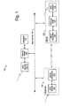
- Fig. 1 illustrates a system 100, in an embodiment of the present invention, that includes a cell-site 102, at least one cell-phone 104, and a network server 106.
- the cell-site 102 comprises a cellular transceiver 108, its reference clock 110, and a GPS receiver-112.
- the cell-phone 104 has a cellular-phone-service-band receiver 114 that is used to track the frequency and phase of signals it receives from the cell-site 102.
- the cell-phone 104 also includes its own GPS receiver-115.
- the network server 106 receives and distributes time information and other data from both the cell-site and cell-phone GPS receivers over a data network 116.
- a database 118 of positions and their time and frequency offsets from GPS time is collected for later reference.
- Passive network synchronization embodiments of the present invention use the cell-site GPS receiver to synchronize the cell-site clocks to GPS time. Then both the cell-phone GPS receiver clock and the cell-phone clock can be synchronized to GPS time by the network server over a network infrastructure, e.g., the Internet.
- a typical GPS receiver generates a one-pulse-per-second (1-PPS) time reference that can be compared and related with timeDiff circuitry to a 1-PPS clock derived from each of the cell-site and cell-phone cellular-telephony radio carriers.
- Other observation intervals besides one second would also work the same way, but the mathematics are simpler when a one second time interval is used.
- Embodiments of the present invention can use three different communication links to transfer time and frequency data.
- One links the GPS reference receivers 112 at the cell-site 102 with the network server 106.
- a second carries software-API or packet-communication between the cell-phone 114 and GPS receiver 115 in the cell-phone, either directly in the cell-phone or indirectly through the network server. Sharing data directly between the receivers helps improve system performance.
- a third connection links the network server 106 and cell-phone to both the cell-phone and GPS receiver.
- the network server 106 can also be located at the cell-site 102 and communicate via the cellular telephony system transceivers 108 and 114.
- Time-difference-of-arrival measurements e.g., from a cell-site to a cell-phone
- TDOA Time-difference-of-arrival measurements
- Time-stamps sent from the cell-site to the cell-phone can be combined with a priori knowledge of the cell-site position, the cell-site clock bias and the cell-site drift from GPS time.
- Such time-stamps can be used to transfer time information from the cell-site to the cell-phone with an accuracy affected only by the radio-signal propagation distance between the cell-phone and the cell-site.
- the corrective frequency offset of the cell-phone carrier-frequency synthesizer loop can be used to estimate the GPS receiver frequency offset. Such estimate is used to reduce the frequency uncertainty and thus reduce the time-to-first-fix, improve receiver sensitivity, and/or reduce the size and power-consumption of the hardware.
- Digital numeric-controlled oscillator (NCO) and analog voltage-controlled oscillator (VCO) are both commonly used in such carrier-frequency synthesizer loops.
- the tempMeas measurement can be used to further improve the frequency-transfer accuracy passing from a cell-phone to a GPS receiver.
- the freqDiff observation can be used alone in frequency transfers without any timeDiff observation.
- the timeDiff observation can also be used without the freqDiff observation for combined time and frequency transfers.
- the time transfer accuracy is preferably improved by reducing the timeDiff hardware quantization noise with software-based filters.
- Cell-phone observations of the cell-site frequency and phase can be used in dual-mode positioning system alternative embodiments of the present invention.
- passive synchronization means the time and frequency offsets of the clocks in the cell-site and cell-phone are only observed with respect to a GPS receiver clock. Calibrations are made later by sending the measured offsets through the communication layers, e.g., using transfer control protocol/Internet protocol (TCP/IP) packets on the Internet.
- TCP/IP transfer control protocol/Internet protocol
- the real clocks in the cell-phone and cell-site are not controlled. The signals from these clocks are merely observed, and the corrective data obtained is not in any way fed back to the source to change the clocks. Rather, the data is used mathematically at the network server and in the GPS receiver software to assist in the GPS-satellite search and then in the position calculation.
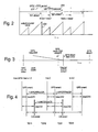
- Fig. 2 diagrams the time relationships between a GPS 1-PPS period 202, a cell 1-PPS period 204, and an output counter value 206.
- a timeDiff observation can be made with a counter circuit that uses a GPS master clock for its input frequency.
- the number of internal clocks are counted between the two event sources, e.g., the internal 1-PPS 202 and the external (or cell) 1-PPS 204.
- the result is periodically output and the counter is restarted, such that for every second of time there will be two counter outputs.
- Both output count values can be combined to estimate a key parameter, the bias between the two clock sources.
- Each restart at the external 1-PPS 204 produces a bias result. If the counter is instead restarted on the internal 1-PPS 202, the result is one minus the bias.
- the external 1-PPS (from the cell-site or cell-phone) can be synchronized to the internal 1-PPS (the GPS receiver) in one of at least two ways, e.g., with a smooth steered or an unsteered internal 1-PPS.
- a GPS 1-PPS timing edge is accurately slaved to GPS system time.
- the GPS 1-PPS timing edge represents "true" GPS time.
- a 1-PPS edge can be generated by a countdown circuit that is started by a 999th-millisecond interrupt derived from the GPS-integer second. An interrupt range of ⁇ 1 millisecond is preferred so that the 1-PPS can be adjusted to occur anywhere between msec-999 and msec-1 in the GPS-integer second.
- a msec-bias error is computed in the GPS receiver as the GPS-millisecond timer to "true" GPS-time error. If the GPS-receiver oscillator drifts from GPS time, such msec-bias error will change. The countdown value will also change to reflect the drift.
- the GPS millisecond counter is preferably adjusted to keep the circuit in range.
- the smooth-steered method embodiment of the present invention is used in GPS receivers at the cell-sites since the msec-bias error is known. Time is known in the GPS receiver and can be passively transferred to the cell-site by measuring any offset between GPS time and a cell-site time reference.
- the time associated with the cell-site 1-PPS can be computed as, TimeCS equals timeGPS+biasCSG.
- the variable biasCSG represents the time offset between the cell-site and GPS time. It is estimated using a function that uses either a snapshot or a filtered estimate using the time-series of the measurements Ni1, Ni2, for all i.
- the unsteered internal 1-PPS method embodiment of the present invention does not use the additional countdown circuit.
- the internal 1-PPS is generated directly from the millisecond interrupt corresponding to the integer GPS second event. Such still requires that the millisecond interrupt that corresponds to the GPS integer second be periodically shifted when the msec-bias error grows beyond a predetermined threshold.
- the time between internal PPS events can be greater or less than one second.
- the step shifts that occur are brief, and do not adversely affect the receiver. It knows when the event will occur, and the 1-msec shift can be accounted for in the computed residual msec-bias error.
- the unsteered reference can be used by a GPS receiver in a cell-phone whenever the position is being requested from the cell-phone user interface.
- GPS receiver is typically not tracking satellites at the moment, and so the GPS msec-bias error will be unknown.
- the time and frequency offset of a particular cell-site is obtained from a network server.
- the position of the cell-site is also useful in the solution calculations.
- the offset between the cell-phone clock and the GPS receiver clock is measured.
- An estimate of the GPS receiver time and frequency offset is computed from GPS time, and is used to reduce the GPS satellite search range.
- the timeDiff observation is used in both the cell-phone and the cell-site to reduce the total number of unknowns in the system.
- the timeDiff measurement is defined herein as the difference in time between two time events generated by two different sources. Both clocks generate a signal with the same expected period based on the expected nominal frequency of each clock. The measurement is the number of clocks between consecutive events.
- “Freq” equals the actual physical frequency that is observed, it also equals baseFreq+drift (eq2).
- the “baseFreq” equals a desired frequency, e.g., the clock is designed to operate at this frequency but appears as “Freq” due to imperfections, aging, and temperature effects, the actual frequency appears.
- “Drift” equals frequency offset between the current frequency and the desired nominal frequency.
- both clocks generate asynchronous one-second time event signal pulses with a specific time interval between.
- a one-second event can be generated with a counter that counts a specific number of reference clocks and then outputs a pulse when the desired count is reached.
- the one-second count number is the nominal crystal frequency.
- the actual time produced is equal to the number of clocks times the "true” period of each clock. Assuming a constant drift, the "true" period of each clock is the "ClockPeriod” variable, which equals the inverse of the frequency in Hertz.
- equation-3 The effect of equation-3 is that with each one-second event, accumulate an additional increment to the total bias.
- the offset can be estimated from GPS time and steer the clock to always be within one clock of the "true" time that was desired at the event.
- the 1-PPS can be left unsteered.
- the total bias is maintained in software and accounted for without a loss of synchronization when all calibration is in software.
- baseGRfreq the expected the frequency of clock used in the GPS receiver (Hz).
- BaseCSfreq the expected frequency of the clock used in the cell-site (Hz).
- FreqGR the actual observed frequency of the GPS receiver (Hz).
- FreqCS the actual observed frequency of the cell-site (Hz).
- BiasGRi the bias of a GPS receiver's 1-PPS from “true” GPS time at time Ti.
- BiasCSi the bias of a cell-site's 1-PPS from "true” GPS time at time Ti.
- DeltaBiasGR12 equals the change in bias in the GPS receiver from t1 to t2.
- DeltaBiasCS12 equals the change in bias in the cell-site from t1 to t2.
- a reference clock and an unknown clock are defined, then the GPS clock is chosen to be the reference. It can synchronized to GPS by tracking the satellites.
- the cell-site is defined to be the unknown clock that is to be synchronized to GPS time.
- TDij The "true" time between the GPS and cell-site events is defined.
- TDij equals “true” time between two consecutive events in the i-th time where the source of the newest event is the j-th source.
- the quantization error is harder to remove when only the timeDiff observable is available, and this motivates gathering the freqDiff measurement. Such allows the quantization noise to be reduced by filtering, and higher frequency clocks are not needed. Avoiding higher frequency clocks allows a system operating power savings to be realized, and is very important in battery-operated portable devices.
- Two important parameters can be estimated from the timeDiff observables, the bias from GPS time of the cell-site, and the frequency drift of the cell-site.
- the frequency drift estimate is then correlated with the bias estimate, and no new information is needed to filter the cell-site bias estimates.
- Fig. 5 represents a redrawing of the timeline and allows the effects of the quantization error to be seen.
- N11 equals three because the first cell-site PPS is reported on MCLK3 due to the clock synchronization.
- the "true" measurement TD11 is equal to the measured count (TD11m) minus the quantization Q1.
- the “true” time difference is the “true” number of clocks (integer plus fraction, which is the quantization) times the period of the clock. Assume the frequency was constant over the interval, then the period is the inverse of the "true” frequency.
- the "truth” model for the ideal measurement is shown below.
- TD11 equals (N11-Q1)/freqGR TD12 equals (N12+Q1)/freqGR TD21 equals (N21-Q2)/freqGR.
- the measured counts are integers.
- the exact frequency of the clock used to count is only an estimate.
- the measurement used is the observed number of counts, times the predicted period which is the inverse of the expected frequency.
- FreqGRhat estimated GPS receiver frequency
- FreqGRhat baseGRfreq+driftGRhat
- DriftGRhat estimated frequency offset from nominal made by the GPS receiver.
- TD11 biasCS1-biasGR1
- TD12 1-biasCS1+biasGR2
- TD21 biasCS2-biasGR2.
- the numeric index on the bias parameters represents their time-tags.
- the first numeric indicator on the TD is the time, the second is the source used to trigger the observation.
- the first measurement to find the error model for the estimate of biasCS1 starts by defining the error to be the "true” one minus the estimated parameter.
- the estimation error is defined as "errorBiasCS11", and is the estimation error of the cell-site bias in the 1 st second using the cell-site PPS as the trigger.
- the first term can be ignored because the GPS drift error is much less than the total frequency.
- the GPS receiver can measure frequency to less than 1Hz at L1.
- the error at the nominal frequency is 1/(1575.42/27.456), which equals 1/57.4 and 0.0174Hz at baseGRfreq. Since N11 can be close to freqGR, this breaks down to 0.0174/freqGR which is 0.63 nanosecond equals 0.19 meter. Such term can be ignored when the drift error is small.
- the second term is the larger error source.
- Q1 is close to one clock, and Q1/baseGRfreq equals 36 nanoseconds or 10.91 meters. If both edges of the master clock are used, an accuracy of eighteen nanoseconds can be realized. Both such edges of the reference clock are used to drive the counter between the consecutive 1-PPS events. The resolution is improved and the worst-case quantization is _/baseGRfreq equals 18 ns equals 5.46 meters.
- a second measurement in the first interval provides a second estimate of the cell-site bias, but with a different GR bias,
- the GPS drift estimation error is small so the first term can be ignored.
- Two estimates are obtained for the cell-site bias in one second with different noise errors.
- BiasCS11hat N11/freqGR1hat+biasGR1hat
- BiasCS21hat 1-N21/freqGR2hat+biasGR2hat
- BiasCS12hat N12/freqGR2hat+biasGR2hat .
- N11, N21, and N12 are the counts from the hardware measurement and freqGRhat and biasGRhat are calculated using the GPS receiver.
- ErrorBiasCS11 -Q1/freqGR1+errorBiasGR1-N11 (errorDriftGR1)/(freqGR1 * freqGR1hat)
- ErrorBiasCS12 -Q1/freqGR2+errorBiasGR2+N12 (errorDriftGR2)/(freqGR2 * freqGR2hat)
- ErrorBiasCS21 -Q2/freqGR2+errorBiasGR2-N21 (errorDriftGR2)/(freqGR2 * freqGR2hat) .
- the quantization error is a uniform random variable with a maximum error of 1/(2*27.456e6), and equals 18ns or 5.46m.
- the numbers given above for the standard deviations for the pseudo-range (PR) and pseudorange-rate (PRR) are for conventional tracking with code and carrier tracking loops.
- An estimate of the cell-site clock drift can be formed using timeDiff data. Two time-difference measurements can be added together to span two external PPS events from a cell-site. The sum of these is an estimate of the time of the cell-site one-second event, where, DriftCS12 equals drift in cell-site clock in the interval between the cell-site PPS events.
- the frequency can be assumed to be constant over the interval so that freqCS1 equals freqCS2,
- TD 1-d/(base+d)
- TD*(base+d) (base+d)-d
- TD*(base+d) base
- TD * d base (1-TD)
- d base (1/ TD-1) .
- DriftCS12 equals baseCSfreq * (1/(TD12-TD21)-1).
- driftCS12 equals baseCSfreq * (freqGR2/(N12+N21+Q1-Q2)-1).
- driftCS12hat equals baseCSfreg * (freqGR2hat/(N12+N21)-1).
- errorDriftCS1 baseCSfreq1 * errorDriftGR2-(Q1-Q2) * freqCS1 .
- the previous cell-site bias estimate is protected forward in time between the two cell-site PPS events.
- a new parameter is defined that is the projection of the previous biasCS estimate with the drift estimate to generate a reference trajectory to filter the new biasCS estimate against.
- BiasCS2Minus biasCS12-driftCS1/(baseCSfreq+driftCS1).
- BiasCS2MinusHat biasCS12hatdriftCS1hat/ (baseCSfreq+driftCS1hat).
- BiasCS2Minus * biasCS12 * (baseCSfreq+driftCS1)-driftCS1
- BiasCS2MinusHat * biasCSfreq+driftCS1hat
- the projection error is defined as, ErrorBiasCS2minus equals biasCS2minus-BiasCS2MinusHat
- ErrorBiasCS2minus errorBiasCS12+(biasSC12hat-biasCS2MinusHat-1) * errorDriftCS1/freqCS1 .
- BiasCS2MinusHat biasCS12hat- driftCS1hat/(baseCSfreq+driftCS1hat) .
- biasCS12hat-BiasCS2hatMinus driftCS1hat/(baseCSfreq+driftCS1hat)
- ErrorBiasCS2minus errorBiasCS12 + (-1+driftCS1hat / (baseCSfreq+driftCS1hat)) * errorDriftCS1/freqCS1
- errorBiasCS2minus errorBiasCS12-((N12+N21)/freqGR2hat) * errorDriftCS1/freqCS1 .
- errorBiasCS12 -Q1/freqGR2+errorBiasGR2+N12 (errorDriftGR2)/(freqGR2 * freqGR2hat).
- baseCSfreq/freqCS1 equals (N12+N21)/freqGR2+(Q1- Q2)/freqGR2.
- a complimentary filter is used to combine the two estimates of the same parameter into a single filtered estimate.
- the noise on the previous filtered estimate is preferably not filtered. If there is an error in the propagation from a previous time to a current time, the error is placed directly into the filtered estimate.
- An optimal filter has a gain of 0.5 when the propagation error is on the same order of magnitude as the noise in a new raw measurement. In this way, some attenuation of the propagation error is obtained.
- BiasCS12filtered (1-a) * biasCS12minusHat+a * biasCS12hat.
- Variable errorBiasCS11 is used instead of errorBiasCS12.
- BiasCS2Minus biasCS11-driftCS1/(baseCSfreq+driftCS1).
- BiasCS2MinusHat biasCS11hat-driftCS1hat/(baseCSfreq+driftCS1hat).
- errorBiasCS2minus errorBiasCS11 - (baseCSfreq/(baseCSfreq+driftCS1hat)) * errorDriftCS1/freqCS1.
- baseCSfreq/(baseCSfreq+driftCS1hat) equals (N12+N21)/freqGR2hat
- errorBiasCS2minus errorBiasCS12-((N12+N21)/freqGR2hat) * errorDriftCS/freqCS1.
- errorBiasCS11 - Q1/freqGR1+errorBiasGR1-N11 (errorDriftGR1)/(freqGR1 * freqGR1hat).
- freqDiff Counting the number of clock pulses from the clock with unknown frequency error in a known time interval generated by the reference clock, forms the freqDiff observable.
- the frequency is computed as the number of clocks divided by the "true" time interval.
- Embodiments of the present invention count the clock pulses with unknown frequency error directly.
- the timeDiff circuits count pulses from the reference clock.
- the quantization error is a uniform random variable between (0,1) and it is not zero mean.
- the data must be pre-whitened to produce a zero-mean measurement error, and conventional techniques can be used in parameter estimating with a quantized noise souce.
- the noise souce becomes a zero-mean process, it may be reduceable with good filtering.
- the previous filtered bias must be propogated to the current time. This is needed to assimilate the new measurement with the previous data in an unbiased manner. The difference between the average bias and the new data is scaled and then added to the propagated estimate to finish the update.
- the propagation error from the timeDiff based-drift estimate has the same error as the new measurement.
- the propagation error is not filtered, and cannot use the timeDiff based-drift estimate in the projection phase.
- Embodiments of the present invention directly count the unknown frequency error clock pulses.
- the timeDiff circuit count pulses from the reference clock.
- the freqDiff measurement is the number of external clocks counted in an interval defined with an integer number of internal clocks.
- An estimate of frequency offset of the internal clock can measure the frequency of the external clock.
- the observed count will be in error by the effects of the quantization of the external clock against the internal master clock at the time the count is started and finished.
- the observation model can be derived from Fig. 6, in which the circuit counts four external clocks.
- the real number is a number that contains a fractional component equal to (Q1-Q2) where Q1 and Q2 have units of counts and are continuous random variables between 0 and 1 count.
- the count observed by the circuit is only N counts.
- the "true” time difference is the number of internal master clocks in the interval times the "true” period of the clock.
- (N/M) * (baseGR+driftGR) equals (Q2-Q1) * (baseGR+driftGR)/M+baseCS+driftCS .
- (N/M) * baseGR-baseCS equals (1/M) * (Q2-Q1) * baseGR+driftCS -driftGR * (1/M) * (- (Q2-Q1)+N) .
- brackets can be replaced by manipulating eqA. (N+(Q1-Q2))/M equals freqCS/freqGR .
- the scale factor in the first term on the left side of the equation is the approximation of the deltaTime based on the nominal GPS receiver frequency.
- this term is the estimate of the total cell-site frequency.
- the left hand side represents the manipulation of the measurement data that produces the frequency difference wanted.
- the error in the frequency estimate is due to the lost fractional cycles over the time interval. The error is reduced by either increasing the cell-site frequency (increasing baseCS which decreases Q1 and Q2), or increasing the time interval (by increasing M).
- the scale factor on the GPS receiver drift term (freqCS/freqGR) produces the translation of the GPS receiver clock frequency from its reference frequency into the reference frequency of the cell-site.
- the freqDiff measurement N is defined as shown below, ⁇ F equals (N/M) * baseGR-baseCS (units are counts at baseCSfreq) error equals (1/M) * (Q2-Q1) * baseGR .
- DriftCS equals ⁇ F+driftGR * (baseCS+driftCS)/(baseGR+driftGR)-error.
- DriftCS * baseGR/(baseGR+driftGR) ⁇ F+driftGR * baseCS/(baseGR+driftGR)-error.
- DriftCS equals ⁇ F * freqGR/baseGR+driftGR * baseCS/baseGR + (1/M) * (Q1-Q2) * freqGR
- DriftCShat ⁇ F * freqGRhat/baseGR+driftGRhat * baseCS/baseGR.
- ⁇ F (N/M) * baseGR-baseCS.
- errorDriftCS errorDriftGR * ⁇ F/baseGR+errorDriftGR * baseCS/baseGR + (1/M) * (Q1-Q2) * freqGR.
- ErrorDriftCS equals ((Q1-Q2)/M) * freqGR+(N/M) * errorDriftGR .
- the quantization error is the sum of two uniform random variables.
- the driftCS estimate from the timeDiff measurement is used to estimate the cell-site frequency offset.
- the freqDiff observation is used instead.
- the freqDiff counter will be used to estimate the external clock frequency as the timeDiff will not provide any information about the external clock when the external PPS is not available.
- both receivers will track the carrier frequency of their respective transmitters.
- the receiver also tracks the phase of the pseudorandom code allowing a pseudorange measurement to be produced.
- the measurement is a time difference of arrival measurement, as the time of transmission is known, and the receiver records the time of arrival with respect to its local clock.
- the GPS satellite has a time and frequency error from "true” GPS time and the "true” desired reference frequency of the spacecraft clock.
- FreqSV equals baseSVfreq+driftSV.
- TimeSV equals timeGPS+biasSV.
- the GPS receiver also has a time and frequency error from GPS time.
- FreqGR equals baseGRfreq+driftGR.
- TimeGR equals timeGPS+biasGR
- a cell-site system with a reference time for all its cell-sites uses cell-site-system time or timeCSS. Such time reference is different from GPS time. It is also possible that the cell-sites are not synchronized to a common time. Embodiments of the present invention do not require that any of the cell-sites have the same time reference.
- FreqCS equals baseCSfreq+driftCS.
- TimeCS equals timeCSS+biasCSS (with respect to cell-site System time). It also equals timeCSG+biasCSG (with respect to GPS time).
- Each cell-site has an offset from timeCSS that is the biasCSS. We can also reference timeCSS to GPS time. The time error for the cell-site changes to biasCSG.
- the cell-phone reference frequency is held constant and the additional frequency required to track the cell-site is made in an additional oscillator or NCO.
- the circuit that produces this additional frequency will generally have a software counter that integrates all the frequency adjustments to produce a number that represents the offset from nominal frequency needed to track the cell-site frequency.
- Such frequency offset is the driven by three processes, (1) the cell-phone offset from its nominal frequency, (2) the Doppler between the cell-phone and the cell-site caused by the projection of the cell-phone user dynamics along the line-of-sight between the cell-phone and the cell-site, and (3) the frequency offset of the cell-site from its nominal frequency.
- the cell-phone outputs a message that contains a total frequency offset number and an associated time tag. Such number is used with the freqDiff and timeDiff observations to synchronize the cell-phone to the GPS receiver clock.
- a cell-site carrier is tracked by adjusting the reference frequency directly with a VCO.
- the voltage is changed to the circuit that produces the different mixdown frequencies.
- the NCO is not needed. If the adjusted reference clock is directly observed with the timeDiff and freqDiff observations, then there is no need for the cell-phone to send any additional information. Any cell-phone bias is replaced by a cell-site range and bias, and any cell-phone drift becomes the rangeRate and cell-site drift.
- the tempMeas observable is very similar to the freqDiff.
- the navigation digital-signal processor preferably includes an oscillator whose frequency is determined by an RC-time constant in which the resistor is actually a thermistor.
- the tempMeas circuit counts the number of cycles of the oscillator in a predetermined interval and gets a measure of temperature from a thermistor calibration curve.
- the GPS clock naturally drifts with temperature.
- the temperature of the complete navigation digital-signal processor based GPS receiver observe that the count and the GPS receiver clock drift (driftGR2hat) is swept at the same time.
- driftGR2hat the GPS receiver clock drift
- the hardware to implement the tempMeas is simply a counter that starts on a GPS predetermined millisecond and ends after a predetermined number of milliseconds later.
- driftGR2HatSCXO While sweeping over the industrial temperature range in the factory (and in the field whenever obtain a reliable GPS fix), observe tempMeas and the driftGR2hat and build the model (and update model in the field) of the driftGR2hat verses the counter value. A tempMeas can then be performed at any time and using this model, an estimate of the GPS receiver clock drift can be obtained. This estimate is called driftGR2HatSCXO.
- SCXO comes from Software-Compensated-Crystal-Oscillator.
- driftGR2hat In the cell-phone, a tempMeas at startup to form driftGR2hat is made. Such estimate will be used during the time and frequency transfer (from the phone to the cell-phone) to reduce the required GPS search range and thus, enable a super-thin GPS client.
- the components of the dual mode system are a GPS satellite, the GPS receiver, the cell-site, and the cell-phone.
- a GPS satellite is being tracked by a GPS receiver at the cell-site whose purpose is to observe the offset of the cell-site clock from GPS time and its frequency reference.
- This receiver and cell-site have known locations and are static. They are physically close enough to allow the physical connection needed to make the timeDiff and freqDiff observations.
- the second GPS receiver is at the cell-phone location.
- the goal is to estimate the location (position and velocity) of the cell-phone. All possible measurement sources to do this.
- the normal GPS pseudorange and pseudorange-rate measurements are used to compute the position, time, and frequency of the GPS receiver at the cell site. Such allows the GPS receiver to synchronize to GPS time, and thus, by observing the relative offset between the cell-site and the GPS receiver time and frequency, can calculate the time and frequency offset of the cell-site from GPS time.
- the inverse is done.
- the cell-phone is assumed to be tracking the cell-site frequency and time. Pseudorange and pseudorange-rate measurements can also be formed for the signal between the cell-phone and the cell-site. Because the cell-site position is known, the cell-site can be used as a ranging source in the same way a GPS satellite is used.
- the pseudorange and pseudorange-rate between the cell-phone and the cell-site can be used as estimates of the cell-phone time and frequency error. Estimates can be made about the GPS receiver's time and frequency using the timeDiff and freqDiff observations, and greatly reduce the search range for the GPS satellites. It can also be used to improve acquisition time and/or acquisition sensitivity.
- the cell system aids the GPS to acquire satellites. After at least one GPS satellite is acquired, the pseudorange and pseudorange-rate between the cell-phone and the cell-site are used along with the GPS pseudoranges and pseudorange-rates in the position calculation. Because of the timeDiff and freqDiff observations, the cell-site time and drift can be expressed in terms of the GPS bias and drift, and the number of unknowns is reduced to the normal unknown as in the stand-alone GPS case.
- Fig. 7 represents a dual-mode system 700 with GPS receiver tracking a satellite vehicle (SV) 702 and a cell-phone 704 tracking a cell-site 706.
- the clocks in the system with respect to the dual-mode system are, SV clock * (numSatellites), GPS receiver-1 clock in the cell-site, GPS receiver-2 clock in the cell-phone, Cell-site clock * (numCellSites), Cell-phone clock .
- PR pseudorange
- PRR pseudorange-rate measurement
- the calibration begins by making a passive connection between a cell-site 706 and cell-phone 704.
- a cell-site clock signal and its 1-PPS can be observed by GPS receiver-1 706. These signals are connected to the freqDiff and timeDiff circuits of a navigation digital-signal processor respectively.
- the cell-phone clock signal and its 1-PPS can be observed by the GPS receiver-2 704.
- Such also has a navigation digital-signal processor chip and such signals are connected to the freqDiff and timeDiff circuits of navigation digital-signal processor respectively.
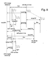
- Fig. 8 represents each clock with its own system time and a corresponding clock bias from this time.
- the sum of these two e.g., the system time plus the bias, produce the reference time used by the hardware for making observations in the receiver.
- the time-difference observations are taken between these time-references.
- the first one, TD1 is between GPS receiver-1 and the cell-site.
- the second one TD2 is between GPS receiver-2 and the cell-phone.
- the clock pulse signals represent a timing signal leaving the transmitter at a known time and arriving at the receiver later in time according to the range.
- the time bias errors cause the observed phase measurement to be affected, e.g., by the bias error of both the transmitter and receiver. Such observations become the pseudoranges.
- TD1 is the timeDiff measurement between the 1-PPS of the GPS receiver-1 and the 1-PPS of the cell-site. Such produces the observation N12 and N21 in units of counts from the receiver-1 and can be used to form timeDiff TD1 in units of seconds.
- TD2 is the timeDiff measurement between the 1-PPS of the GPS receiver-1 and the 1-PPS of the cell-site. Such produces the observation N12 and N21 in units of counts from the receiver-2 and can be used to form timeDiff TD1 in units of seconds.
- the units of measure for the pseudorange measurements are preferably maintained in units of seconds rather meters, in order to simplify things in terms of the timeDiff and freqDiff. But the units in meters can be used too.
- the phase measurement that was produced to make the local phase of the signal-generated in the cell-phone track the received phase of the signal transmitted by the cell-site can be accessed.
- biasSV + rangeGR2 biasGR2 + ⁇ GR2
- biasSV + rangeGR1 biasGR1 + ⁇ GR1.
- ECEF earth-centered-earth-fixed
- the GPS receiver-1 at the cell-site has a known position that is near the cell-site position, but does not need to be identical to it.
- posGPS1 (x1, y1, z1)
- velGPS1 (xVel1, yVel1, zVel1)
- the GPS satellite position is assumed to be known from the ephemeris model that is distributed around the system.
- the satellite velocity is calculated from the ephemeris.
- PosSV (xSV, ySV, zSV)
- VelSV (xVelSV, yVelSV, zVelSV).
- the GPS receiver-2 has a cell-phone and its loaction represents the main unknown in the system. All the other unknowns are nuisance parameters in the system that need to be solved or eliminated.
- RangeGR1 k * ((xSV-x1) 2 +(ySV-y1) 2 (zSV-z1) 2 ) 1/2 .
- RangeGR2 k * ((xSV-x) 2 +(ySV-y) 2 (zSV-z) 2 ) 1/2 .
- RangeCP k * ((xCP-x) 2 +(yCP-y) 2 (zCP-z) 2 ) 1/2 .
- K the inverse of the speed of light, e.g., 2.99792458e8 meters/second.
- Fig. 9 is a visualization of how the freqDiff measurement can be taken and used.
- a freqDiff1 measurement is obtained between GPS receiver-1 reference and the cell-site reference.
- the freqDiff2 measurement is obtained between GPS receiver-2 reference and the cell-phone reference.
- the same reference e.g., the nominal frequency used in the GPS receiver, is used for both the GPS receivers.
- Part of the strategy is to employ the same hardware solution that contains the navigation digital-signal processor chip at both the reference stations for DGPS and data, cell-sites, and client (cell-phone) solutions.
- the same frequency reference can be assumed, which is the nominal crystal frequency used to generate all the frequencies used to track the GPS satellite carrier.
- the range-rate measurements are not included in the freqDiff figure, the pseudoranges are in the timeDiff figure.
- the freqDiff observations are not affected by the user or satellite motion.
- the range and cell-site clock effects do appear in the cell-phone reference frequency.
- the raw measurement from the freqDiff circuit are the counts N1 from GPS receiver-1 and N2 from GPS receiver-2.
- the freqDiff in units of cycles/sec at the cell-site reference frequency can be computed with these.
- BaseCS baseCP can be assumed.
- ⁇ F1 (N1/M) * baseGR-baseCS (Hz at baseCSfreq)
- An estimate of frequency from the cell-phone is required to track the cell-site carrier.
- the method embodiment of the present invention is used with an NCO.
- the cell-phone can output a number that can be scaled into units of cycles/sec at the baseCP frequency.
- ⁇ DotCP rangeRateCP+driftCS-driftCP (Hz at baseCSfreq)
- the VCO is steered to track the cell-site carrier and the effect on the cell-phone nominal frequency is observed directly in the timeDiff and freqDiff circuit. It is still possible that the numerical representation of the frequency offset from nominal can be output. However, there is a different meaning of the frequency component due to the cell-phone clock that appears in freqDiff. Now the freqDiff will observe the Doppler component of the cell-phone motion and the frequency offset of the cell-site.
- the receiver must increase its generated frequency to track this addition frequency offset from nominal. If the receiver has a positive frequency offset, then it must reduce its generated frequency to track the carrier. Finally, if there is a positive Doppler between the transmitter and receiver, then the receiver must increase its frequency to track this effect.
- DriftCPvco rangeRateCP+driftCS .
- phase error discriminator that produces the updates to the VCO frequency must remove the drift of the cell-phone.
- the counter will observe the integer number of cycles of the frequency freqCPvco to track the cell-site, rather than just the cell-phone frequency freqCP.
- the measurement can be modeled as the derivative of the pseudorange.
- the GPS receiver at the cell-site can be assumed to have a "true" user velocity of zero. Thus, all the positions and velocities are assumed known.
- the GPS receiver 112 at the cell-site can compute its position, or the position can be a surveyed position. Secondly, the satellite position and velocity can be computed with the ephemeris made available to the cell-site GPS receiver.
- RangeRateGR1 and driftSV are known, can use the observed pseudorange-rate can be used to estimate the GPS receiver drift.
- driftGR1hat rangeRateGR1+driftSV- ⁇ DotGR1 (units are Hz at baseGRfreq).
- the drift estimate can be formed from the velocity fix, or by averaging a set of the above equations if the position is known. Such will improve the accuracy of the estimate if the position accuracy is high.
- freqDiff can be used to express the cell-site drift in terms of the GPS receiver drift. This removes the cell-phone clock from the measured cell-phone carrier frequency to track the cell-site carrier.
- DriftCPhat ⁇ F2+driftGR2 * (baseCSfreq/baseGRfreq).
- ⁇ DotCP rangeRateCP+driftsCShat -( ⁇ F2+driftGR2 * (baseCSfreq/baseGRfreq)) (Hz at baseCSfreq) .
- this procedure can be used to generate an estimate of the clock drift of the GPS receiver clock in the cell-phone.
- An estimate of the drift can be formed by assuming that the cell-phone is static, so that the rangeRateCP term can be assumed to be zero. The accuracy of the estimate is driven by the accuracy of this assumption. However, for most low cost clocks, the frequency uncertainty caused by temperature and aging on the crystal are much larger than the user dynamics between the cell-phone and cell-site, and the estimate provides a huge information gain that can be used to reduce search time and or increase sensitivity.
- the PPM remains the same at any reference frequency.
- the freqError in Parts-Per-Million (PPM), 235Hz/1575.42 .15PPM
- the frequency error of the crystal may be on the order of .5 to 1PPM, and the assumption of zero-user-velocity still provides a big information gain in estimating the GPS receiver frequency drift.
- DriftCPhat rangeRateCP+driftCShat- ⁇ DotCP (Hz at baseCSfreq)
- FreqDiffVCO ((Nvco+(Q1-Q2)/M) * freqGR (in counts at CP freq).
- ⁇ F2vco rangeRateCP+driftCShat-driftGR2 * (baseCSfreq/baseGRfreq) (in Hertz at CP freq).
- the user velocity is zero. Such allows an estimate of the clock drift of the GPS receiver in the cell-phone.
- DriftGR2hat (driftCShat- ⁇ F2vco) * baseGRfreq/basecsfreq (in Hertz at GR freq).
- This estimate can be used to reduce the frequency search required to find the GPS satellites.
- frequency transfer can be performed with this observation.
- ⁇ DotCP rangeRateCP+driftsCShat-( ⁇ F2+driftGR2 * (baseCSfreq/baseGRfreq)).
- ⁇ F2vco rangeRateCP+driftCShat-driftGR2 * (baseCSfreq/baseGRfreq).
- PrrCP C3 * rangeRateCP-driftGR2 * C1+C2
- PrrCP ⁇ DotCP
- C1 (baseCSfreq/baseGRfreq)
- C2 driftsCShat- ⁇ F2
- C3 1/ ( ⁇ CP)
- ⁇ CP C/baseCSfreq.
- ⁇ C/baseCPfreq.
- timeDiff measurements To removing unknowns for the timeDiff and pseudoranges, the timeDiff measurements must be used.
- the rangeGR1 is considered to be a known quantity since its components are known.
- the satellite position and clock bias is considered known since it can be computed from the GPS ephemeris that can be circulated around the system by the server.
- GPS receiver-1 is tracking enough satellites to compute at least its time solution. If its position is known, then only one satellite is needed to do this.
- ⁇ GR1 rangeGR1+biasSV-biasGR1.
- ⁇ GR2 rangeGR2+biasSV-biasGR2.
- biasCSG BiasGR1+TD1.
- biasCPG BiasGR2+TD2.
- TD1 N11/freqGR1hat
- TD2 N12/freqGR1hat
- FreqGRhat baseGRfreq+driftGR1hat .
- biasGR1hat and driftGR1hat are known and are obtained directly from GPS receiver-1 at the cell-site.
- ⁇ CP rangeCP+BiasCS-BiasCP.
- the measurement is not a linear function of driftGR because it represents up in both the numerator and denominator (inside freqGR) of the second term. While this can be handled, it is inconvenient. Thus, perform a simple approximation that linearizes the model. Replace the freqGR in the denominator with simply baseGRfreq.
- driftGR/(baseGRfreq * freqGR) driftGR/(baseGRfreq * baseGRfreq).
- driftGR 20PPM.
- N11 was almost exactly equal to baseGR. That means the cell-site is just to the left of the GPS 1-PPS.
- driftGR/freqGR is proportional to driftGR.
- the tempMeas observable are used.
- the driftGR to an accuracy of +/.5PPM can be estimated.
- the tempMeas will provide a good enough approximation for using the cell-phone pseudorange to predict the GPS receiver clock bias. Such can be used for prepositioning.
- TD1 N11/baseGRfreq-N11 * driftGR/(freqGR * baseGR)
- TD1a N11/baseGRfreq
- TD1a TD1+N11 * driftGR/(freqGR * baseGR)
- TD1 biasCPhat-biasGR2hat.
- TD1a biasCPhat-biasGR2hat+N11 * driftGR2/(baseGRfreq * baseGRfreq)
- BiasCPhat N11/baseGR+biasGR2hat-N11 * driftGR/(baseGRfreq * baseGRfreq) .
- ⁇ CP rangeCP+BiasCShat - (N11/baseGR+biasGR2hat-N11 * driftGR/(baseGRfreq * baseGRfreq) .
- D1 1
- D2 biasCShat-N11/baseGR+N11 * driftGR/(baseGRfreq * baseGRfreq) (seconds)
- D3 1/C (units of seconds/meter) .
- biasGR2hat rangeCP+BiasCShat- ⁇ cp + (N11/baseGR-N11 * driftGR/(baseGRfreq * baseGRfreq).
- This equation gives a method to estimate the GPS receiver clock bias prior to tracking any GPS signals.
- the maximum time-search window is one-millisecond.
- a clock bias estimate with an error that is significantly less than one millisecond is needed.
- the cell-phone is only one kilo-meter (1000m) from the cell-site. Such is possible in Japan where the cell-site density is quite high.
- ⁇ F2 driftCP-driftGR2 * (baseCSfreq/baseGRfreq)
- DriftGR2hat (driftCShat- ⁇ DotCP- ⁇ F2) * (baseGRfreq/baseCSfreq)
- biasGR2hat (1000/c)+biasCShat- ⁇ cp + N11/baseGR-N11 * (driftCShat- ⁇ DotCP- ⁇ F2)/(baseCSfreq * baseGRfreq) .
- the time-uncertainty has been reduced from 1msec to 3.3microsecond. That is an information gain of almost a factor of 300. Such is the kind of information gain that will allow a super-thin GPS client.
- the timeDiff no longer observes the cell-phone bias, but rather, it observes the cell-site bias and the range between the cell-site and the cell-phone. For example, if the cell-site clock bias is positive, then the cell-site must also increase its phase to be in alignment. To compensate for the travel time of the signal from the cell-site to the cell-phone, the cell-phone must further delay its signal in order to track the incoming signal. A phase advance is a positive increase in the phase.
- the cell-phone clock bias is replaced by the rangeCP and the cell-site bias.
- TD1a N11/baseGRfreq .
- TD1a TD1+N11 * driftGR/(baseGRfreq * baseGRfreq).
- TD1a rangeCP+biasCShat-biasGR2+N11 * driftGR/(baseGRfreq * baseGRfreq) .
- D1 1
- D2 baseCShat -N11/baseGR+N11 * driftGR/(baseGRfreq * baseGRfreq) (seconds)
- D3 1/C (units of seconds/meter) .
- BiasGR2 rangeCP+biasCShat-N11/ baseGRfreq+N11 * driftGR2/(baserGRfreq * baseGRfreq).
- biasGR2hat rangeCP+biasCShat-N11/ baseGRfreq+N11 * driftGR2SCXO/(baserGRfreq * baseGRfreq).
- DriftGR2hat (driftCShat- ⁇ F2vco) * baseGRfreq/baseCSfreq (in Hertz at GR freq).
- biasGR2 rangeCP+biasCShat-N11/ baseGRfreq+N11 * (driftCShat-AF2vco)/(baserCSfreq * baseGRfreq) (units are seconds)
- D1 1
- D2 biasCShat-N11/baseGR+N11 * driftGR/(baseGRfreq * baseGRfreq) (seconds)
- D3 1/C (units of seconds/meter).
- D1 1
- D2 baseCShat -N11/baseGR+N11 * driftGR/(baseGRfreq * baseGRfreq) (seconds)
- D3 1/C (units of seconds/meter).
- the delta vector as the error between the "true” position vector and the starting estimate of the position. In the estimation process, compute the delta vector and then add it to the starting position to get the position estimate. Thus, assume that when forming the predicted quantities where the user position is needed, use xNominal.
- the Dual Mode system has derived the solution equations that relate all observable in the system to the user position/velocity and clock bias and drift of the GPS receiver in the cell-phone. All other system clocks have been calibrated out of the system.
- the cell-phone measurements along with the timeDiff, freqDiff, and tempMeas observables can be used to improve the acquisition of the GPS satellites by reducing the search range for those signals. Estimate the GPS receiver clock bias and drift with respect to the cell-phone and the calibration of the cell-sites.
- the system is a truly distributed processing system. Depending on the client type, all the calibrations and calculation could either be done in the cell-phone, in the network server, or spread between the two systems.
- the server is the conduit that sends the calibration numbers for the cell-sites so that the data can be used for both time and frequency transfer that improves GPS acquisition times, and for Dual mode operation where use the range and range-rates from both systems to compute the cell-phone position.
- a communications means between the cell-site, the server, the cell-phone, and the GPS receivers at both the cell-site and the cell-phone is assumed. However, the details of the specific methods used are not critical to the equations presented here.
- GPS receiver-1 is at the cell site. It tracks GPS continuously and estimates its position, clock bias and clock drift. It performs a timeDiff and freqDiff between the GPS receiver and the Cell-site clock. It sends the measurements and its solutions back to the network server. Server computes the cell-site clock bias and drift. It also send other GPS data to the network server such as the 50bps Navigation data message.
- the network server accepts the data from the cell-site and builds a table of the clock bias and drift of each cell-site. It also can generate a cell-site position from the GPS receiver position.
- the network server builds a Navigation Data database that is distributed throughout the system as a source of data for computing the satellite position, velocity, clock bias and drift.
- GPS receiver-2 is at the cell-phone to compute the position of this receiver. At turn on, don't know the GPS receiver clock bias, drift, or position. It performs a timeDiff, freqDiff, and tempMeas.
- the cell-phone receiver tracks a cell-site (at least one). By tracking the phase and frequency of the carrier, it can also form pseudoranges and pseudorange-rates between the cell-site. Using these measurements, plus the cell-site data that includes the cell-site clock bias and drift, and the cell-site position, and using the timeDiff, freqDiff, and tempMeas observations, can perform time and frequency transfer between the cell-phone and the GPS receiver. After acquitting one GPS satellite, can also use the observations to compute the dual-mode position/velocity.
- the time and frequency transfer allows us to improve the acquisition of the GPS satellites by reducing the search range. Such improves acquisition time and sensitivity. Such allows the super-thin-client.
- the range and range-rate measurements from both systems can be combined to compute the cell-phone position.
- Such should allow a positioning capability when fewer than normal of the measurements from each system are available.
- a three-dimensional fix can be made with only 1 GPS satellites, and 3 cell-sites, or 2GPS satellites and 2 cell-sites, or 3 GPS satellites and only one cell-site.
- GPS-navigation almanac and ephemeris are acquired and reduced by the Webserver 106 with its own reference-station GPS-receiver to supply simple polynomials that respectively represent each satellite's position and velocity.
- Such polynomials will, of course, go stale over time, but periodic contact between the cell-site 102 and webserver 106 via the Internet are critically depended upon to provide fresh-enough orbit data.
- the GPS receiver 112 is therefore relieved of the storage-intensive requirement to hold current ephemeris and almanac data in local RAM/ROM, and relieved of the processor-intensive job of locally computing double-precision floating-point math the satellite-orbit positions for every position fix.
- the webserver 106 is owned and operated by an independent service provider. Per-use or subscription fees are charged to users who operate the cell-phone 104 and/or cell-site 102.
- the cell-phone 104 is alternatively further bundled in an intellectual property (IP) package for semiconductor integrated circuit device designs of application-specific network clients. Such IP is sold for a license fee and hardware-device cost to original equipment manufacturers (OEM's) of network clients.
- IP intellectual property
- the GPS receiver 112 In operation, the GPS receiver 112 must simultaneously search for GPS-microwave signals in two domains, e.g., frequency and code-phase.
- the local oscillator and Doppler shift caused by satellite vehicle relative velocity create carrier frequency uncertainties that are resolved.
- the instantaneous GPS-satellite pseudo-random number (pseudo-random number) code phase is another unknown.
- Received signals that are above the "noise floor" are relatively easy and quick to search. But weak signals, as exist inside buildings, are buried in as much as twenty decibels of noise. Each visit to a frequency/code-phase bin must dwell there long enough to "beat down" the noise floor with processing gains provided by code correlators. Weak signals also require that the search bins have finer steps between bin frequencies and bin code-phase, e.g., due to aliasing. So more bins are needed to be searched and each bin needs more processing dwell, all of which increases search time exponentially.
- the webserver 106 publishes real-time navigation data to the Internet.
- Other services currently exist that put up partial or non-real-time navigation and initialization data on the Internet, and these can be used partially in place of, or to check the validity of real-time navigation data being sent to the GPS receiver 112.
- a primary and critical role job for webserver 106 is the off-loading of navigation-computational chores from the GPS receiver 112. The degree to which such off-loading can be carried depends on the regularity of communication contact that can be realized between the GPS receiver 112 and the webserver 106. The actual measurements obtained by the GPS receiver 112 are forwarded to the webserver 106.
- Alternative embodiments of the present invention incorporate webservers 106 that do database processing for higher-level abstractions and purposes.
- the server platform includes a health and quality monitor for checking said static observations and preventing an inclusion of incorrect information in said database of measurement errors and satellite data messages.
- webserver 106 could collect position solution information over time for the pattern of locations that GPS receiver 112 visits over a period of hours, days, weeks, months, years, etc. Such information can then be processed to estimate where the user of GPS receiver 112 is, where the user has been, or where the user is likely to be in the future. Such information is useful to dispatch, time-clock, house-arrest, deployment, inventory, asset management, military, security, and other kinds of applications.
- Position information can be interpreted to intelligently guess at what the user is doing at any one moment. For example, if the user's position matched that of a local grocery store, the user could be assumed to be shopping. Logs can also be generated by the user at the webserver 106, e.g., by city maintenance department collocating with and "marking" in the electronic database the permanent location of a fire hydrants, power transformers, roadways, etc.
- the presence on the Internet of information about a user's position can be used by advertisers and marketers to direct contextual messages to the user in real-time. Such data is sold in real-time in a business model embodiment of the present invention.
- embodiments of the present invention use Internet webservers to process data collected by remote GPS receivers in such ways that signal sensitivity is increased and search times are shortened compared to conventional receivers and methods.
- Recent test data indicates the a priori worst-case modeling error for a typical crystal frequency is around ⁇ 0.5 PPM ( ⁇ 787Hz) with temperature modeling.
- a frequency range of ⁇ 1000 Hz for the first satellite is preferably searched. If there is a high degree of confidence about the frequency information learned in a first search, the frequency search range of subsequent satellites can be constrained to save time and effort. Alternatively, such searching-time savings could be traded for a slower clock speed as would be found in less expensive hardware.
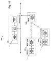
- Fig. 10 is a functional block diagram of a second infrastructure-assisted navigation system embodiment of the present invention, and is referred to herein by the general reference numeral 1000.
- system 1000 is needed is where no political or economic opportunity exists to include a GPS receiver at a cellular-telephone base site, e.g., system 100 (Fig. I). So a cell-phone and GPS receiver combination permanently parked at a stationary location can be adapted to serve instead.
- a business model embodiment of the present invention deploys apparently ordinary cellphones on fixed station in each cell site where business coverage is needed but not otherwise available. Such non-availability can result from hostile base cell-site operators, adverse or cumbersome laws, too little time, too much expense, etc.
- System 1000 includes a service provider 1002 connected to a data network 1004, e.g., the Internet.
- a cellular base station 1006 simply handles ordinary cellular telephone calls between stations with telephone numbers.
- a visiting, mobile cell user 1008 is able to make and receive telephone calls through the cellular base station 1006.
- a business that operates the service provider 1002 has previously deployed a permanent, parked cell station 1010 that is within the service area of the cellular base station 1006. It too is accessible to other parts of the system via telephone calls made through the cellular base station 1006.
- the service provider 1002 includes a GPS receiver 1012, a network server 1014, and a database 1016 for storing temperature, time, and frequency data and models.
- the cell-site 1006 comprises a cellular transceiver 1018 and no GPS receiver.
- the cell-phone 1008 also includes its own GPS receiver 1020 and cellular transceiver 1022.
- the permanent, parked cell station 1010 has a GPS receiver 1024 and a cellular-phone-service-band transceiver 1026 that is used to track the frequency and phase of signals it receives from the cell-site 1006.
- the network server 1014 receives and distributes time information and other data from both the cell-site and cell-phone GPS receivers over data network 1004.
- a database 1016 of positions and their time and frequency offsets from GPS time is collected for later reference.
- three hardware-based measurements can be used to synchronize the local clocks in two independent systems, e.g., (1) time-difference, (2) frequency difference, and (3) crystal temperature-versus-frequency models. Any or all three can be used to synchronize clocks.
- timeDiff observable if the time difference between time events from two different time sources is known, the time of an event at one time source can be used to compute the time of the event at the other time source.
- freqDiff observable if the frequency difference between two clocks is known, then finding the frequency of one can be used to predict the frequency of the other.
- a temperature-frequency calibration model is used to predict the frequency of a local GPS clock by measuring the crystal temperature. If one of the time sources is a GPS receiver, other clocks can be related to GPS time. Such potentially allows devices all around the world to be time and frequency synchronized to a common and stable reference, for example, the GPS system atomic clocks.
- Passive network synchronization embodiments of the present invention use the GPS receiver 1024 to measure the cell-site 1006 clocks in GPS time. Then the cell-phone GPS receiver 1020 clock and the cell-phone 1022 clock can be synchronized to GPS time by the network server over a network infrastructure, e.g., the Internet.
- a typical GPS receiver generates a one-pulse-per-second (1-PPS) time reference that can be compared and related with timeDiff circuitry to a 1-PPS clock derived from each of the cell-site and cell-phone cellular-telephony radio carriers.
- Other observation intervals besides one second would also work the same way, but the mathematics are simpler when a one second time interval is used.
- Embodiments of the present invention can use three different communication links to transfer time and frequency data.
- One links the GPS reference receivers 1024 with the network server 1014.
- a second carries software-API or packet-communication between the cell-phone 1022 and GPS receiver 1020 in the cell-phone, either directly in the cell-phone or indirectly through the network server. Sharing data directly between the GPS receivers helps improve system performance.
- a third connection links the network server 1014 to both the cell-phone 1022 and GPS receiver 1020.
- Time-difference-of-arrival measurements e.g., from a cell-phone 1010 to a cell-phone 1008, can be used for positioning inside a combined cell-phone and GPS receiver to improve positioning availability and accuracy.
- Time-stamps sent from the cell-phone 1010 to the cell-phone 1008 can be combined with a priori knowledge of the cell-phone 1010 position, the cell-phone 1010 clock bias and the cell-site 1006 drift from GPS time.
- Such time-stamps can be used to transfer time information from the cell-phone 1010 to the cell-phone 1008 with an accuracy affected only by the radio-signal propagation distance between.
- the corrective frequency offset of the cell-phone carrier-frequency synthesizer loop is again used here in this embodiment to estimate the GPS receiver frequency offset. Such estimate is used to reduce the frequency uncertainty and thus reduce the time-to-first-fix, improve receiver sensitivity, and/or reduce the size and power-consumption of the hardware.
- Digital numeric-controlled oscillator (NCO) and analog voltage-controlled oscillator (VCO) are both commonly used in such carrier-frequency synthesizer loops.
- Any tempMeas measurement can be used to further improve the frequency-transfer accuracy passing from a cell-phone to a GPS receiver, e.g., by building temperature models.
- the freqDiff observation can be used alone in frequency transfers without any timeDiff observation.
- the timeDiff observation can also be used without the freqDiff observation for combined time and frequency transfers.
- the time transfer accuracy is preferably improved by reducing the timeDiff hardware quantization noise with software-based filters.
- Cell-phone observations of the cell-phone 1010 frequency and phase can be used in dual-mode positioning system alternative embodiments of the present invention.
- passive synchronization means the time and frequency offsets of the clocks in the cell-phone 1010 and cell-phone are only observed with respect to a GPS receiver clock. Calibrations are made later by sending the measured offsets through the communication layers, e.g., using transfer control protocol/Internet protocol (TCP/IP) packets on the Internet.
- TCP/IP transfer control protocol/Internet protocol
- the real clocks in the cell-phone and cell-phone 1010 are not controlled.
- the signals from these clocks are merely observed, and the corrective data obtained is not in any way fed back to the source to change the clocks. Rather, the data is used mathematically at the network server and in the GPS receiver software to assist in the GPS-satellite search and then in the position calculation.
Landscapes
- Engineering & Computer Science (AREA)
- Radar, Positioning & Navigation (AREA)
- Remote Sensing (AREA)
- Physics & Mathematics (AREA)
- General Physics & Mathematics (AREA)
- Computer Networks & Wireless Communication (AREA)
- Automation & Control Theory (AREA)
- Position Fixing By Use Of Radio Waves (AREA)
- Mobile Radio Communication Systems (AREA)
- Navigation (AREA)
- Traffic Control Systems (AREA)
Abstract
Description

These observations can be made,
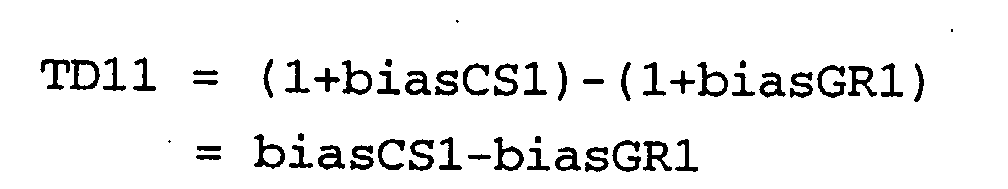
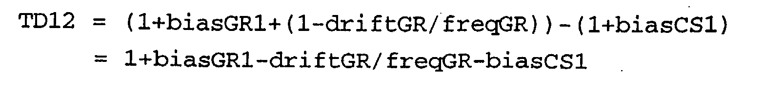


TD11 equals (N11-Q1)/freqGR
TD12 equals (N12+Q1)/freqGR
TD21 equals (N21-Q2)/freqGR.
TD11m = N11/freqGRhat = 3/freqGRhat
TD12m = N12/freqGRhat = 1/freqGRhat
TD21m = N21/freqGRhat = 2/FreqGRhat.
where,
FreqGRhat = estimated GPS receiver frequency
FreqGRhat = baseGRfreq+driftGRhat
DriftGRhat = estimated frequency offset from nominal made by the GPS receiver.
TD11 = biasCS1-biasGR1
TD12 = 1-biasCS1+biasGR2
TD21 = biasCS2-biasGR2.


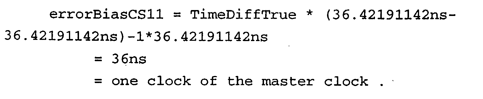

BiasCS11hat = N11/freqGR1hat+biasGR1hat
BiasCS21hat = 1-N21/freqGR2hat+biasGR2hat
BiasCS12hat = N12/freqGR2hat+biasGR2hat .
Where N11, N21, and N12 are the counts from the hardware measurement and freqGRhat and biasGRhat are calculated using the GPS receiver.

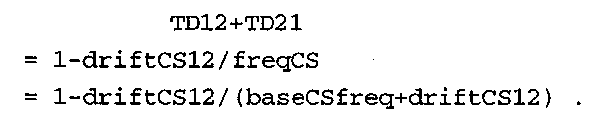
freqGR = baseGRfreq+driftGR
freqGRhat = baseGRfreq+driftGRhat
ErrorDriftCS = driftCS-driftCShat
ErrorDriftGR = driftGR-driftGRhat,
The complimentary filter has the form,

m equals k if k < Kmax
m equals Kmax if k > Kmax
deltaTime(K) equals time between t=K and t=K-1.
Note, if Kmax equals infinity, then the filter output is the average of all the data.
ClockCount equals freqCS * DeltaTimeTrue .

FreqSV equals baseSVfreq+driftSV.
TimeSV equals timeGPS+biasSV.
FreqGR equals baseGRfreq+driftGR.
TimeGR equals timeGPS+biasGR
"FreqCS" equals baseCSfreq+driftCS. "TimeCS" equals timeCSS+biasCSS (with respect to cell-site System time). It also equals timeCSG+biasCSG (with respect to GPS time).

SV clock * (numSatellites),
GPS receiver-1 clock in the cell-site,
GPS receiver-2 clock in the cell-phone,
Cell-site clock * (numCellSites),
Cell-phone clock .
N1=freqDiff in counts from navigation digital-signal processor1
N2=freqDiff in counts from navigation digital-signal processor2.
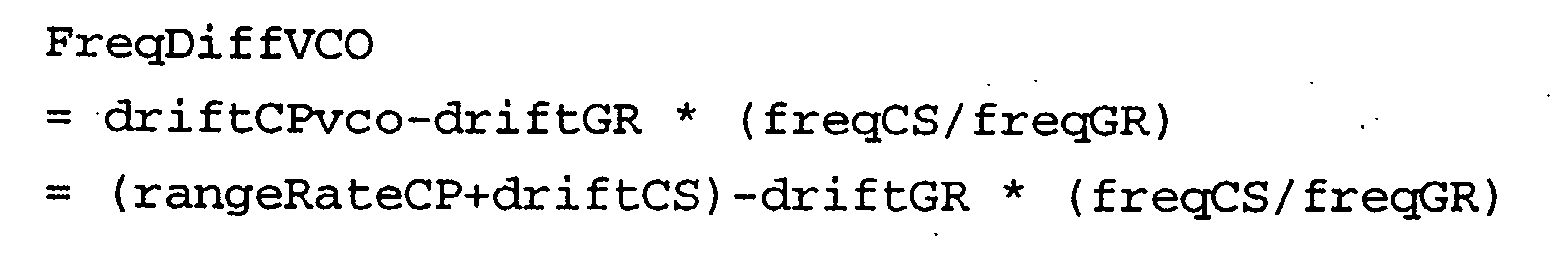
DotGR1 = rangeRateGR1+driftSV-driftGR1;
DotGR2 = rangeRateGR2+driftSV-driftGR2.
where,
"true" user velocity vector = (xVel, yVel, zVel) .
Remember:
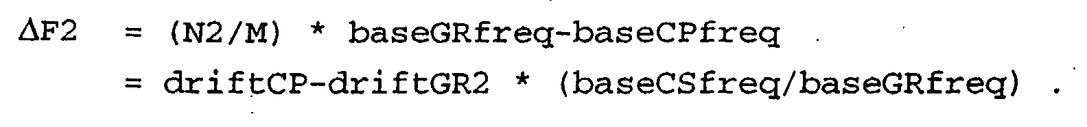
λCP= C/f = speed-of-light/27.456e6 cycle/sec = 10.9 meters/cycle.
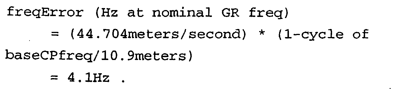
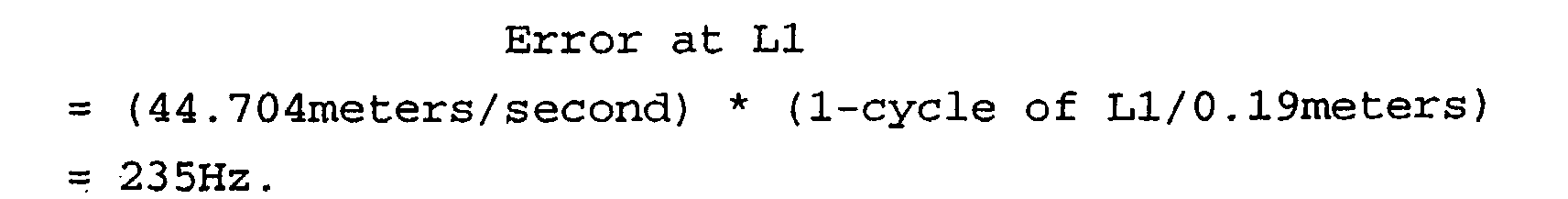

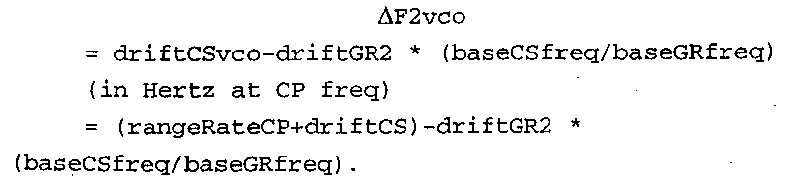
where for a method embodiment of the present invention, PrrCP = DotCP
C1 = (baseCSfreq/baseGRfreq)
C2 = driftsCShat-ΔF2
C3 = 1/ (λCP)
λCP = C/baseCSfreq.
C1 = (baseCSfreq/baseGRfreq)
C2 = driftsCShat
C3 = 1/ (λCell-site)
λ = C/baseCPfreq.
Combine the cell-phone and GPS pseudorange rate measurements to estimate the user velocity and, the GPS receiver drift.
C4 = 1
C5 = driftSVhat (from the satellite ephemeris)
C6 = 1/ (λGR)
(λ-GR) = C/baseGRfreq
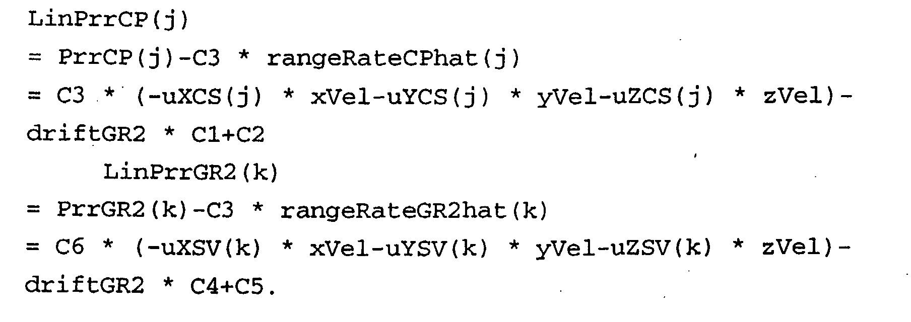
using N11, then
BiasCS1hat = TD1+biasGR1hat
(units are seconds),
using N12, then
BiasCS1hat = 1-TD2+biasGR1hat
(units are seconds)
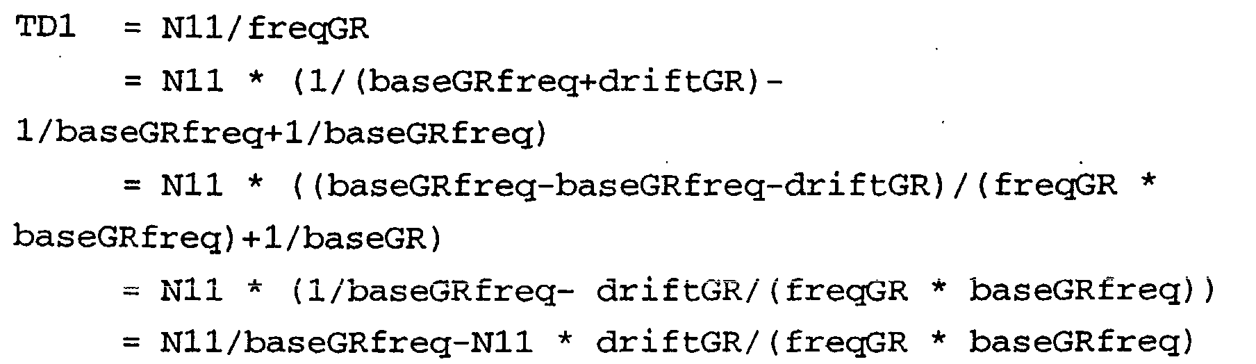
Solving for the "true" value,
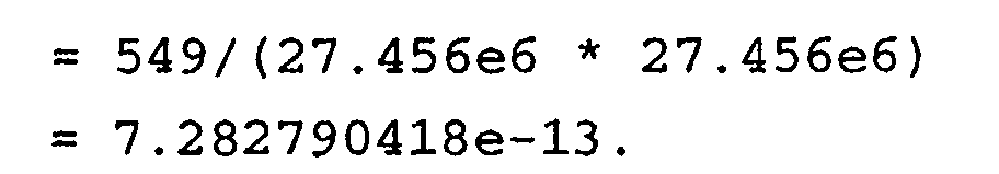
Recall the measurement model,
For GPS, the maximum time-search window is one-millisecond. Thus, in order to reduce the search range, a clock bias estimate with an error that is significantly less than one millisecond is needed.
delX = x-xNominal
delY = y-yNominal
delZ = z-zNominal

Claims (16)
- A satellite-navigation system, comprising,
a first satellite-navigation receiver that provides for a first position solution;
a first wireless communications device collocated with the first satellite-navigation receiver and connected to share at least one of time and frequency measurements with the first satellite-navigation receiver;
a second satellite-navigation receiver for providing an accurate time and frequency estimate;
a second wireless communications device collocated with the second satellite-navigation receiver and able to make radio contact with the first wireless communications device; and
a webserver for post-processing of said first position solution with said accurate time and frequency estimate and for extracting a more accurate second position solution for the first satellite-navigation receiver, and connected by a data network to the second satellite-navigation receiver and second wireless communications device. - The system of claim 1, wherein:the second satellite-navigation receiver and second wireless communications device are at a fixed location anda local differential correction measurement is obtained and communicated to the webserver for providing increased accuracy position solutions for the first satellite-navigation receiver.
- The system of claim 1, wherein:the webserver provides information to the first satellite-navigation receiver that reduces at least one of local-oscillator frequency uncertainty and time uncertainty, and provides for improved satellite search times and sensitivity.
- The system of claim 3, wherein:the webserver computes time-difference information by comparing time measurements between the first and second satellite-navigation receiver as communicated over a radio contact and said data network.
- The system of claim 3, wherein:the webserver computes frequency-difference information by comparing carrier frequency measurements between the first and second wireless communication devices, and such measurements are communicated over a radio contact and said data network.
- A satellite-navigation system, comprising,
a first satellite-navigation receiver that provides for a user position solution;
a cell-phone collocated with the first satellite-navigation receiver and connected to share time and frequency measurements with the first satellite-navigation receiver;
a second satellite-navigation receiver for providing an accurate time and frequency estimate;
a base cellular telephone site collocated with the second satellite-navigation receiver and able to make radio contact with the cell-phone; and
a webserver for post-processing of said user position solution with said accurate time and frequency estimate and for extracting a more accurate second position solution for the first satellite-navigation receiver, and connected by a data network to the second satellite-navigation receiver and base cellular telephone site. - The system of claim 6, wherein:the second satellite-navigation receiver and base cellular telephone site are at a fixed location and a local differential correction measurement is obtained and communicated to the webserver for providing increased accuracy position solutions for the first satellite-navigation receiver.
- The system of claim 6, wherein:the webserver provides information to the first satellite-navigation receiver that reduces at least one of local-oscillator frequency uncertainty and time uncertainty, and provides for improved satellite search times and sensitivity.
- The system of claim 8, wherein:the webserver computes time-difference information by comparing time measurements between the first and second satellite-navigation receiver as communicated over a cellular radio contact and said data network.
- The system of claim 8, wherein:the webserver computes frequency-difference information by comparing carrier frequency measurements between cellular telephone devices, and such measurements are communicated over a cellular radio contact and said data network.
- The system of claim 3, wherein:the webserver collects temperature measurement (tempMeas) observables and stores them in a database from which it later builds a temperature-frequency model used to improve receiver sensitivity and acquisition performance in a software-compensated-crystal-oscillator (SCXO).
- The system of claim 1, wherein:a minimum of one GPS satellite and three cell site base stations are used in a dual mode system configuration.
- The system of claim 3, wherein:the webserver includes a global positioning system (GPS) digital signal processor (DSP) application specific integrated circuit (ASIC) that integrates time-difference, frequency-difference, and temperature-measurement infrastructure-information for improved satellite acquisition and receiver sensitivity.
- The system of claim 1, wherein:position-solution calculations are distributed amongst the webserver and the wireless communications devices.
- A satellite-navigation system, comprising,
a first satellite-navigation receiver that provides for a first position solution;
a first cell-phone collocated with the first satellite-navigation receiver and connected to make and share at least one of time and frequency measurements made with the aid of the first satellite-navigation receiver;
a second satellite-navigation receiver for providing an accurate time and frequency estimate;
a second cell-phone collocated with the second satellite-navigation receiver and able to make a telephone connection with the first cell-phone through a cellular base station located in the area; and
a webserver with telephone access to each of the cell-phones via the cellular base station, and for post-processing of said first position solution with said accurate time and frequency estimate and for extracting a more accurate second position solution for the first satellite-navigation receiver, and connected by a data network to the second satellite-navigation receiver and second cell-phone;
wherein, the first satellite-navigation receiver and first cell-phone are permanently parked at a stationary location and are continually accessible to the webserver. - A navigation system comprises a cell-phone, a base cellular telephone site, and a webserver, wherein each are paired with a global positioning system (GPS) receiver;
wherein, a GPS receiver associated with the cell-phone is aided with information received from the cell-site and webserver that help reduce satellite search uncertainty with time-difference and/or frequency-difference measurements taken with data collected from what the cell-phone and its GPS receiver assume to be accurate time and frequency; and
wherein, correction information is used in post-processing of any velocity solutions computed by the cell-phone to arrive at more-precise determinations.
Applications Claiming Priority (2)
| Application Number | Priority Date | Filing Date | Title |
|---|---|---|---|
| US797521 | 2001-02-28 | ||
| US09/797,521 US6473030B1 (en) | 2001-02-28 | 2001-02-28 | Infrastructure-aiding for satellite navigation receiver and method |
Publications (2)
| Publication Number | Publication Date |
|---|---|
| EP1237008A2 true EP1237008A2 (en) | 2002-09-04 |
| EP1237008A3 EP1237008A3 (en) | 2005-01-12 |
Family
ID=25171067
Family Applications (1)
| Application Number | Title | Priority Date | Filing Date |
|---|---|---|---|
| EP02004516A Withdrawn EP1237008A3 (en) | 2001-02-28 | 2002-02-27 | Infrastructure and method for providing aiding information to a GPS receiver |
Country Status (5)
| Country | Link |
|---|---|
| US (1) | US6473030B1 (en) |
| EP (1) | EP1237008A3 (en) |
| JP (1) | JP3574436B2 (en) |
| CN (2) | CN101339236B (en) |
| HK (1) | HK1049371A1 (en) |
Cited By (4)
| Publication number | Priority date | Publication date | Assignee | Title |
|---|---|---|---|---|
| WO2004063763A1 (en) * | 2003-01-07 | 2004-07-29 | Global Locate, Inc. | Method and apparatus for performing timing synchronization |
| EP1340996A3 (en) * | 2002-02-19 | 2005-02-02 | eRide, Inc. | Satellite Navigation Receiver System and Reference Station Network Server |
| EP2827176A1 (en) * | 2013-07-16 | 2015-01-21 | O2 Micro, Inc. | Method and receiver for determining system time of a navigation system |
| WO2019173875A1 (en) * | 2018-03-14 | 2019-09-19 | Locata Corporation Pty Ltd | Method and apparatus for synchronising a location network |
Families Citing this family (116)
| Publication number | Priority date | Publication date | Assignee | Title |
|---|---|---|---|---|
| US6411892B1 (en) | 2000-07-13 | 2002-06-25 | Global Locate, Inc. | Method and apparatus for locating mobile receivers using a wide area reference network for propagating ephemeris |
| US9020756B2 (en) * | 1999-04-23 | 2015-04-28 | Global Locate, Inc. | Method and apparatus for processing satellite positioning system signals |
| US7970411B2 (en) | 2000-05-18 | 2011-06-28 | Sirf Technology, Inc. | Aided location communication system |
| US6462708B1 (en) * | 2001-04-05 | 2002-10-08 | Sirf Technology, Inc. | GPS-based positioning system for mobile GPS terminals |
| US8078189B2 (en) | 2000-08-14 | 2011-12-13 | Sirf Technology, Inc. | System and method for providing location based services over a network |
| US7970412B2 (en) | 2000-05-18 | 2011-06-28 | Sirf Technology, Inc. | Aided location communication system |
| US7949362B2 (en) | 2000-05-18 | 2011-05-24 | Sirf Technology, Inc. | Satellite positioning aided communication system selection |
| US6684158B1 (en) * | 2001-02-28 | 2004-01-27 | Sirf Technology, Inc. | Method for aiding a global positioning system |
| US7929928B2 (en) | 2000-05-18 | 2011-04-19 | Sirf Technology Inc. | Frequency phase correction system |
| US7236883B2 (en) | 2000-08-14 | 2007-06-26 | Sirf Technology, Inc. | Aiding in a satellite positioning system |
| US6931233B1 (en) | 2000-08-31 | 2005-08-16 | Sirf Technology, Inc. | GPS RF front end IC with programmable frequency synthesizer for use in wireless phones |
| JP2004510138A (en) | 2000-09-20 | 2004-04-02 | コーニンクレッカ フィリップス エレクトロニクス エヌ ヴィ | Method for determining the position of a mobile device |
| US7254402B2 (en) * | 2000-10-12 | 2007-08-07 | Qualcomm Incorporated | GPS satellite signal acquisition assistance system and method in a wireless communications network |
| US7574215B1 (en) * | 2000-11-06 | 2009-08-11 | Trimble Navigation Limited | System and method for distribution of GPS satellite information |
| US7196660B2 (en) | 2000-11-17 | 2007-03-27 | Global Locate, Inc | Method and system for determining time in a satellite positioning system |
| US6937187B2 (en) | 2000-11-17 | 2005-08-30 | Global Locate, Inc. | Method and apparatus for forming a dynamic model to locate position of a satellite receiver |
| US7769076B2 (en) | 2001-05-18 | 2010-08-03 | Broadcom Corporation | Method and apparatus for performing frequency synchronization |
| US7006556B2 (en) * | 2001-05-18 | 2006-02-28 | Global Locate, Inc. | Method and apparatus for performing signal correlation at multiple resolutions to mitigate multipath interference |
| US7925210B2 (en) * | 2001-05-21 | 2011-04-12 | Sirf Technology, Inc. | Synchronizing a radio network with end user radio terminals |
| US7668554B2 (en) | 2001-05-21 | 2010-02-23 | Sirf Technology, Inc. | Network system for aided GPS broadcast positioning |
| US7877104B2 (en) * | 2001-05-21 | 2011-01-25 | Sirf Technology Inc. | Method for synchronizing a radio network using end user radio terminals |
| US20080186229A1 (en) * | 2001-06-06 | 2008-08-07 | Van Diggelen Frank | Method and Apparatus for Monitoring Satellite-Constellation Configuration To Maintain Integrity of Long-Term-Orbit Information In A Remote Receiver |
| US8212719B2 (en) * | 2001-06-06 | 2012-07-03 | Global Locate, Inc. | Method and apparatus for background decoding of a satellite navigation message to maintain integrity of long term orbit information in a remote receiver |
| US6651000B2 (en) | 2001-07-25 | 2003-11-18 | Global Locate, Inc. | Method and apparatus for generating and distributing satellite tracking information in a compact format |
| US6950058B1 (en) * | 2001-10-17 | 2005-09-27 | Sirf Technology, Inc. | System, method, apparatus and means for providing GPS aiding data to networked receivers |
| US6856282B2 (en) * | 2002-02-08 | 2005-02-15 | Qualcomm Incorporated | Directly acquiring precision code GPS signals |
| US6647339B2 (en) * | 2002-02-19 | 2003-11-11 | Seiko Epson Corporation | Shared reference station |
| US6724342B2 (en) * | 2002-04-19 | 2004-04-20 | Sirf Technology, Inc. | Compensation for frequency adjustment in mobile communication-positioning device with shared oscillator |
| US7155183B2 (en) * | 2003-01-16 | 2006-12-26 | Global Locate, Inc. | Method and apparatus for adjusting reference oscillator frequency in a mobile wireless device |
| JP3794413B2 (en) * | 2003-02-28 | 2006-07-05 | セイコーエプソン株式会社 | Positioning system and positioning terminal |
| US6958953B2 (en) * | 2003-05-13 | 2005-10-25 | International Business Machines Corporation | Real time clock circuit having an internal clock generator |
| US8971913B2 (en) | 2003-06-27 | 2015-03-03 | Qualcomm Incorporated | Method and apparatus for wireless network hybrid positioning |
| US8483717B2 (en) | 2003-06-27 | 2013-07-09 | Qualcomm Incorporated | Local area network assisted positioning |
| US7228138B2 (en) * | 2003-12-05 | 2007-06-05 | Sony Ericsson Mobile Communications Ab | Methods, servers, mobile stations, and computer program products using GPS referenced time and delay information in messages for GPS time assistance |
| KR100566277B1 (en) * | 2003-12-09 | 2006-03-30 | 삼성전자주식회사 | How to acquire GPS signal in user terminal |
| GB2409376B (en) * | 2003-12-17 | 2006-06-28 | Motorola Inc | A subscriber unit, a cellular communication system and a method for determining a location therefor |
| JP3876893B2 (en) * | 2004-05-14 | 2007-02-07 | セイコーエプソン株式会社 | TERMINAL DEVICE, POSITIONING METHOD, TERMINAL DEVICE CONTROL PROGRAM, COMPUTER-READABLE RECORDING MEDIUM CONTAINING TERMINAL DEVICE CONTROL PROGRAM |
| US7319878B2 (en) | 2004-06-18 | 2008-01-15 | Qualcomm Incorporated | Method and apparatus for determining location of a base station using a plurality of mobile stations in a wireless mobile network |
| US20060116131A1 (en) * | 2004-11-30 | 2006-06-01 | Morgan Scott D | Reporting satellite positioning system assistance integrity information in wireless communication networks |
| US8032276B2 (en) * | 2004-12-07 | 2011-10-04 | Geotab, Inc. | Apparatus and method for optimally recording geographical position data |
| US7019688B1 (en) | 2005-03-24 | 2006-03-28 | Honeywell International Inc. | LAAS ground facility sigma monitor |
| US7961717B2 (en) | 2005-05-12 | 2011-06-14 | Iposi, Inc. | System and methods for IP and VoIP device location determination |
| JP4186952B2 (en) * | 2005-05-25 | 2008-11-26 | セイコーエプソン株式会社 | TERMINAL DEVICE, POSITIONING SYSTEM, TERMINAL DEVICE CONTROL METHOD, PROGRAM, AND RECORDING MEDIUM |
| US7459984B2 (en) | 2005-05-26 | 2008-12-02 | Sirf Technology Holdings, Inc. | Method and apparatus for self-calibration and adaptive temperature compensation in GPS receivers |
| DE202005021930U1 (en) * | 2005-08-01 | 2011-08-08 | Corning Cable Systems Llc | Fiber optic decoupling cables and pre-connected assemblies with toning parts |
| JP4215040B2 (en) * | 2005-10-11 | 2009-01-28 | セイコーエプソン株式会社 | POSITIONING SYSTEM, TERMINAL DEVICE, TERMINAL DEVICE CONTROL METHOD, TERMINAL DEVICE CONTROL PROGRAM, COMPUTER-READABLE RECORDING MEDIUM CONTAINING TERMINAL DEVICE CONTROL PROGRAM |
| US9042917B2 (en) | 2005-11-07 | 2015-05-26 | Qualcomm Incorporated | Positioning for WLANS and other wireless networks |
| US20070153837A1 (en) * | 2005-12-30 | 2007-07-05 | Alon Meir | Device, system and method of frequency tracking for clock and data recovery |
| US20070182631A1 (en) * | 2006-02-09 | 2007-08-09 | Berlinsky Allan M | Internet based assisted global positioning system |
| CN101043315B (en) * | 2006-06-12 | 2011-08-03 | 华为技术有限公司 | Network clock synchronous device, system and method |
| US8345658B2 (en) * | 2006-10-18 | 2013-01-01 | Nec Corporation | Mobile communication terminal with GPS function, positioning system, operation control method, and program |
| US9226257B2 (en) | 2006-11-04 | 2015-12-29 | Qualcomm Incorporated | Positioning for WLANs and other wireless networks |
| US8089400B1 (en) * | 2007-06-11 | 2012-01-03 | Zte (Usa) Inc. | Network assisted GPS positioning for Femto Cells in wireless networks |
| US20100231444A1 (en) * | 2007-10-26 | 2010-09-16 | Panasonic Corporation | Positioning receiver and positioning method |
| US7598907B2 (en) * | 2007-12-06 | 2009-10-06 | Kyocera Corporation | System and method for WWAN/WLAN position estimation |
| JP2009002958A (en) * | 2008-08-05 | 2009-01-08 | Seiko Epson Corp | Terminal device, terminal device control method, and terminal device control program. |
| US8370063B2 (en) * | 2008-10-29 | 2013-02-05 | Telenav, Inc. | Navigation system having filtering mechanism and method of operation thereof |
| US9140776B2 (en) * | 2008-11-04 | 2015-09-22 | Sensewhere Limited | Assisted positioning systems |
| US8625572B2 (en) * | 2008-12-19 | 2014-01-07 | Nokia Corporation | Synchronization indication in networks |
| US20090129208A1 (en) * | 2009-01-28 | 2009-05-21 | Weiss Kenneth P | Apparatus, system and method for keeping time |
| JP5423036B2 (en) * | 2009-02-18 | 2014-02-19 | セイコーエプソン株式会社 | Position calculation method and position calculation apparatus |
| CN101937073B (en) * | 2009-06-30 | 2012-11-28 | 凹凸电子(武汉)有限公司 | GPS satellite carrier frequency detection method and device and GPS receiver |
| US20110068976A1 (en) * | 2009-09-21 | 2011-03-24 | Gm Global Technology Operations, Inc. | Method and apparatus for accelerating the process of determining a geographic position |
| US8259010B2 (en) * | 2009-10-14 | 2012-09-04 | Qualcomm Incorporated | Qualifying coarse position injection in position determination systems |
| US20130222583A1 (en) * | 2012-02-28 | 2013-08-29 | Research In Motion Limited | System and Method for Obtaining Images from External Cameras Using a Mobile Device |
| JP2013197882A (en) | 2012-03-19 | 2013-09-30 | Seiko Epson Corp | Frequency difference arithmetic circuit, satellite signal receiver, and frequency difference arithmetic method |
| US8643444B2 (en) | 2012-06-04 | 2014-02-04 | Broadcom Corporation | Common reference crystal systems |
| US9369843B2 (en) | 2012-12-28 | 2016-06-14 | Trimble Navigation Limited | Extracting pseudorange information using a cellular device |
| US9835729B2 (en) | 2012-12-28 | 2017-12-05 | Trimble Inc. | Global navigation satellite system receiver system with radio frequency hardware component |
| US10101465B2 (en) | 2012-12-28 | 2018-10-16 | Trimble Inc. | Electronic tape measure on a cellphone |
| US9462446B2 (en) | 2012-12-28 | 2016-10-04 | Trimble Navigation Limited | Collecting external accessory data at a mobile data collection platform that obtains raw observables from an internal chipset |
| US9456067B2 (en) | 2012-12-28 | 2016-09-27 | Trimble Navigation Limited | External electronic distance measurement accessory for a mobile data collection platform |
| US9488736B2 (en) | 2012-12-28 | 2016-11-08 | Trimble Navigation Limited | Locally measured movement smoothing of GNSS position fixes |
| US9645248B2 (en) | 2012-12-28 | 2017-05-09 | Trimble Inc. | Vehicle-based global navigation satellite system receiver system with radio frequency hardware component |
| US9544737B2 (en) | 2012-12-28 | 2017-01-10 | Trimble Inc. | Performing data collection based on external raw observables using a mobile data collection platform |
| US9602974B2 (en) | 2012-12-28 | 2017-03-21 | Trimble Inc. | Dead reconing system based on locally measured movement |
| US9467814B2 (en) | 2012-12-28 | 2016-10-11 | Trimble Navigation Limited | Collecting external accessory data at a mobile data collection platform that obtains raw observables from an external GNSS raw observable provider |
| US9880286B2 (en) | 2012-12-28 | 2018-01-30 | Trimble Inc. | Locally measured movement smoothing of position fixes based on extracted pseudoranges |
| US9903957B2 (en) | 2012-12-28 | 2018-02-27 | Trimble Inc. | Global navigation satellite system receiver system with radio frequency hardware component |
| US9612341B2 (en) * | 2012-12-28 | 2017-04-04 | Trimble Inc. | GNSS receiver positioning system |
| US9910158B2 (en) | 2012-12-28 | 2018-03-06 | Trimble Inc. | Position determination of a cellular device using carrier phase smoothing |
| US9821999B2 (en) | 2012-12-28 | 2017-11-21 | Trimble Inc. | External GNSS receiver module with motion sensor suite for contextual inference of user activity |
| US9538336B2 (en) | 2012-12-28 | 2017-01-03 | Trimble Inc. | Performing data collection based on internal raw observables using a mobile data collection platform |
| US9945959B2 (en) | 2012-12-28 | 2018-04-17 | Trimble Inc. | Global navigation satellite system receiver system with radio frequency hardware component |
| US9429640B2 (en) | 2012-12-28 | 2016-08-30 | Trimble Navigation Limited | Obtaining pseudorange information using a cellular device |
| US9639941B2 (en) | 2012-12-28 | 2017-05-02 | Trimble Inc. | Scene documentation |
| US9638803B2 (en) | 2013-05-06 | 2017-05-02 | Accord Software & Systems Pvt. Ltd. | Navigation data configuration for optimal time to first fix |
| US9730068B2 (en) * | 2013-10-22 | 2017-08-08 | Honeywell International Inc. | System and method for visitor guidance and registration using digital locations |
| US9923626B2 (en) | 2014-06-13 | 2018-03-20 | Trimble Inc. | Mobile ionospheric data capture system |
| CN104238408A (en) * | 2014-09-02 | 2014-12-24 | 国家电网公司 | Pulse time tick expanding device |
| CN105842724B (en) | 2015-01-15 | 2018-07-17 | 江苏南大五维电子科技有限公司 | A kind of ship auxiliary anchors alongside the shore method and system |
| CN112578408B (en) | 2015-03-06 | 2024-10-22 | 看门人系统公司 | A low-power positioning system and positioning method for movable objects |
| US10001541B2 (en) | 2015-09-04 | 2018-06-19 | Gatekeeper Systems, Inc. | Magnetometer and accelerometer calibration for cart navigation system |
| US9731744B2 (en) | 2015-09-04 | 2017-08-15 | Gatekeeper Systems, Inc. | Estimating motion of wheeled carts |
| IL250459B2 (en) * | 2017-02-05 | 2023-09-01 | Israel Aerospace Ind Ltd | Navigation systems and methods |
| EP4553803A1 (en) | 2017-03-08 | 2025-05-14 | Gatekeeper Systems, Inc. | Navigation systems for wheeled carts |
| JP2018155665A (en) * | 2017-03-17 | 2018-10-04 | セイコーエプソン株式会社 | Timing signal output device, electronic device and moving body |
| US10523684B2 (en) * | 2017-10-02 | 2019-12-31 | Higher Ground Llc | Forward path congestion mitigation for satellite communications |
| CN108345013B (en) * | 2018-04-16 | 2023-09-01 | 南京天际易达通信技术有限公司 | A Method of Improving the Receiving Sensitivity of Satellite Navigation Signals |
| US10904828B2 (en) * | 2018-05-09 | 2021-01-26 | Position Location and Repeaters PRB | Aligning GNSS location determination with wireless wide area network paging slots |
| US10880028B2 (en) * | 2018-11-13 | 2020-12-29 | The United States Of America, As Represented By The Secretary Of The Navy | System and method for clock-skew-based covert communication |
| US10466655B1 (en) | 2018-12-27 | 2019-11-05 | Seiko Epson Corporation | Electronic timepiece and control method of electronic timepiece |
| US12352871B2 (en) * | 2019-11-27 | 2025-07-08 | Qualcomm Incorporated | Management of concurrent GNSS reception and wireless transmission |
| US11681052B2 (en) * | 2020-01-07 | 2023-06-20 | All. Space Networks Limited | Non-cooperative position, navigation, and timing extraction from VSAT communications signals using multi-beam phased array antenna |
| US11048717B1 (en) | 2020-06-16 | 2021-06-29 | Geotab Inc. | Dataset simplification of N-dimensional signals captured for asset tracking |
| US12229092B2 (en) | 2020-07-31 | 2025-02-18 | Geotab Inc. | Methods and systems for fixed extrapolation error data simplification processes for telematics |
| US11609888B2 (en) | 2020-07-31 | 2023-03-21 | Geotab Inc. | Methods and systems for fixed interpolation error data simplification processes for telematics |
| US11556509B1 (en) | 2020-07-31 | 2023-01-17 | Geotab Inc. | Methods and devices for fixed interpolation error data simplification processes for telematic |
| US11593329B2 (en) | 2020-07-31 | 2023-02-28 | Geotab Inc. | Methods and devices for fixed extrapolation error data simplification processes for telematics |
| CN114114352B (en) * | 2020-08-31 | 2025-04-01 | 中兴通讯股份有限公司 | Frequency compensation method and circuit, storage medium, and electronic device |
| US11546395B2 (en) | 2020-11-24 | 2023-01-03 | Geotab Inc. | Extrema-retentive data buffering and simplification |
| US11838364B2 (en) | 2020-11-24 | 2023-12-05 | Geotab Inc. | Extrema-retentive data buffering and simplification |
| CN114660581B (en) * | 2022-03-18 | 2023-06-23 | 中国电子科技集团公司第十研究所 | Asynchronous Burst Signal Ranging Method Based on Extrinsic Information Assistance |
| CN115309032B (en) * | 2022-08-08 | 2025-03-04 | 深圳市远东华强导航定位有限公司 | A clock signal correction method, terminal device and storage medium |
| US12471055B2 (en) * | 2023-06-29 | 2025-11-11 | Here Global B.V. | Methods and apparatuses for high-precision positioning using floating clock models |
| CN117289256B (en) * | 2023-11-24 | 2024-01-30 | 成都本原星通科技有限公司 | Target long-distance high-precision tracking method based on low-orbit communication satellite |
Family Cites Families (8)
| Publication number | Priority date | Publication date | Assignee | Title |
|---|---|---|---|---|
| US5280629A (en) * | 1991-12-06 | 1994-01-18 | Motorola, Inc. | Technique for measuring channel delay |
| US6308077B1 (en) * | 1992-10-02 | 2001-10-23 | Motorola, Inc. | Apparatus and method for providing synchronization of base-stations in a communication system |
| US6131067A (en) * | 1995-10-09 | 2000-10-10 | Snaptrack, Inc. | Client-server based remote locator device |
| KR100241725B1 (en) * | 1997-08-02 | 2000-02-01 | 윤종용 | Synchronizing method in distributed networking system and apparatus thereof |
| US6070078A (en) * | 1997-10-15 | 2000-05-30 | Ericsson Inc. | Reduced global positioning system receiver code shift search space for a cellular telephone system |
| US6538600B1 (en) * | 1998-10-16 | 2003-03-25 | Lucent Technologies Inc. | Wireless assisted GPS using a reference location |
| US6184829B1 (en) * | 1999-01-08 | 2001-02-06 | Trueposition, Inc. | Calibration for wireless location system |
| US6334059B1 (en) * | 1999-01-08 | 2001-12-25 | Trueposition, Inc. | Modified transmission method for improving accuracy for e-911 calls |
-
2001
- 2001-02-28 US US09/797,521 patent/US6473030B1/en not_active Expired - Lifetime
-
2002
- 2002-02-27 EP EP02004516A patent/EP1237008A3/en not_active Withdrawn
- 2002-02-28 JP JP2002053188A patent/JP3574436B2/en not_active Expired - Fee Related
- 2002-02-28 CN CN2008101297109A patent/CN101339236B/en not_active Expired - Fee Related
- 2002-02-28 CN CNB021065578A patent/CN100422760C/en not_active Expired - Fee Related
-
2003
- 2003-02-27 HK HK03101483.9A patent/HK1049371A1/en unknown
Cited By (5)
| Publication number | Priority date | Publication date | Assignee | Title |
|---|---|---|---|---|
| US6829534B2 (en) | 1999-04-23 | 2004-12-07 | Global Locate, Inc. | Method and apparatus for performing timing synchronization |
| EP1340996A3 (en) * | 2002-02-19 | 2005-02-02 | eRide, Inc. | Satellite Navigation Receiver System and Reference Station Network Server |
| WO2004063763A1 (en) * | 2003-01-07 | 2004-07-29 | Global Locate, Inc. | Method and apparatus for performing timing synchronization |
| EP2827176A1 (en) * | 2013-07-16 | 2015-01-21 | O2 Micro, Inc. | Method and receiver for determining system time of a navigation system |
| WO2019173875A1 (en) * | 2018-03-14 | 2019-09-19 | Locata Corporation Pty Ltd | Method and apparatus for synchronising a location network |
Also Published As
| Publication number | Publication date |
|---|---|
| US6473030B1 (en) | 2002-10-29 |
| US20020167441A1 (en) | 2002-11-14 |
| EP1237008A3 (en) | 2005-01-12 |
| JP3574436B2 (en) | 2004-10-06 |
| HK1049371A1 (en) | 2003-05-09 |
| JP2002357652A (en) | 2002-12-13 |
| CN1373371A (en) | 2002-10-09 |
| CN101339236B (en) | 2011-11-16 |
| CN100422760C (en) | 2008-10-01 |
| CN101339236A (en) | 2009-01-07 |
Similar Documents
| Publication | Publication Date | Title |
|---|---|---|
| US6473030B1 (en) | Infrastructure-aiding for satellite navigation receiver and method | |
| EP1306688B1 (en) | Method and apparatus for determining time in a satellite positioning system | |
| EP1851564B1 (en) | Method and apparatus for enhanced autonomous gps | |
| KR101068322B1 (en) | Time Determination Method in Satellite Positioning System Receiver | |
| EP1697756B1 (en) | Method and apparatus for monitoring the integrity of satellite tracking data used by a remote receiver | |
| US7869948B2 (en) | Method and apparatus in positioning without broadcast ephemeris | |
| US6975266B2 (en) | Method and apparatus for locating position of a satellite signal receiver | |
| EP1581820B1 (en) | Method and system for performing timing synchronization | |
| US20080111738A1 (en) | Method and apparatus in standalone positioning without broadcast ephemeris | |
| KR101000984B1 (en) | Method and apparatus for verifying position using distance change rate measurement in satellite positioning system | |
| US20120293366A1 (en) | System, method and computer program for ultra fast time to first fix for a gnss receiver | |
| US6417800B1 (en) | Method for determining reference time error and an electronic device | |
| JP2003240836A (en) | Method and system for calculating position from calculation time | |
| EP1752784B1 (en) | Cellphone GPS positioning system | |
| US20010008393A1 (en) | Method for performing positioning and an electronic device | |
| AU2005226022A1 (en) | Method for back-up dual-frequency navigation during brief periods when measurement data is unavailable on one of two frequencies | |
| US7456782B2 (en) | Timing calibration for fast signal reacquisition in navigational receivers | |
| EP1512028B1 (en) | Aiding in a satellite positioning system | |
| EP1115009A2 (en) | A method for performing positioning and an electronic device | |
| MXPA06005288A (en) | Method and apparatus for monitoring the integrity of satellite tracking data used bya remote receiver | |
| HK1121808B (en) | Method and apparatus for validating a position in a satellite positioning system using range-rate measurements | |
| HK1120308B (en) | Method and apparatus for enhanced autonomous gps |
Legal Events
| Date | Code | Title | Description |
|---|---|---|---|
| PUAI | Public reference made under article 153(3) epc to a published international application that has entered the european phase |
Free format text: ORIGINAL CODE: 0009012 |
|
| AK | Designated contracting states |
Kind code of ref document: A2 Designated state(s): AT BE CH CY DE DK ES FI FR GB GR IE IT LI LU MC NL PT SE TR |
|
| AX | Request for extension of the european patent |
Free format text: AL;LT;LV;MK;RO;SI |
|
| PUAL | Search report despatched |
Free format text: ORIGINAL CODE: 0009013 |
|
| AK | Designated contracting states |
Kind code of ref document: A3 Designated state(s): AT BE CH CY DE DK ES FI FR GB GR IE IT LI LU MC NL PT SE TR |
|
| AX | Request for extension of the european patent |
Extension state: AL LT LV MK RO SI |
|
| 17P | Request for examination filed |
Effective date: 20050314 |
|
| AKX | Designation fees paid |
Designated state(s): DE FR GB |
|
| STAA | Information on the status of an ep patent application or granted ep patent |
Free format text: STATUS: THE APPLICATION HAS BEEN WITHDRAWN |
|
| 18W | Application withdrawn |
Effective date: 20140408 |
|
| REG | Reference to a national code |
Ref country code: HK Ref legal event code: WD Ref document number: 1049371 Country of ref document: HK |