EP1236926A2 - Pneumatic connections for vehicle suspensions - Google Patents
Pneumatic connections for vehicle suspensions Download PDFInfo
- Publication number
- EP1236926A2 EP1236926A2 EP02075557A EP02075557A EP1236926A2 EP 1236926 A2 EP1236926 A2 EP 1236926A2 EP 02075557 A EP02075557 A EP 02075557A EP 02075557 A EP02075557 A EP 02075557A EP 1236926 A2 EP1236926 A2 EP 1236926A2
- Authority
- EP
- European Patent Office
- Prior art keywords
- disposed
- piston rod
- assembly
- housing
- connector
- Prior art date
- Legal status (The legal status is an assumption and is not a legal conclusion. Google has not performed a legal analysis and makes no representation as to the accuracy of the status listed.)
- Granted
Links
Images


Classifications
-
- B—PERFORMING OPERATIONS; TRANSPORTING
- B60—VEHICLES IN GENERAL
- B60G—VEHICLE SUSPENSION ARRANGEMENTS
- B60G13/00—Resilient suspensions characterised by arrangement, location or type of vibration dampers
- B60G13/001—Arrangements for attachment of dampers
- B60G13/003—Arrangements for attachment of dampers characterised by the mounting on the vehicle body or chassis of the damper unit
-
- F—MECHANICAL ENGINEERING; LIGHTING; HEATING; WEAPONS; BLASTING
- F16—ENGINEERING ELEMENTS AND UNITS; GENERAL MEASURES FOR PRODUCING AND MAINTAINING EFFECTIVE FUNCTIONING OF MACHINES OR INSTALLATIONS; THERMAL INSULATION IN GENERAL
- F16F—SPRINGS; SHOCK-ABSORBERS; MEANS FOR DAMPING VIBRATION
- F16F9/00—Springs, vibration-dampers, shock-absorbers, or similarly-constructed movement-dampers using a fluid or the equivalent as damping medium
- F16F9/02—Springs, vibration-dampers, shock-absorbers, or similarly-constructed movement-dampers using a fluid or the equivalent as damping medium using gas only or vacuum
- F16F9/0209—Telescopic
- F16F9/0281—Details
-
- F—MECHANICAL ENGINEERING; LIGHTING; HEATING; WEAPONS; BLASTING
- F16—ENGINEERING ELEMENTS AND UNITS; GENERAL MEASURES FOR PRODUCING AND MAINTAINING EFFECTIVE FUNCTIONING OF MACHINES OR INSTALLATIONS; THERMAL INSULATION IN GENERAL
- F16F—SPRINGS; SHOCK-ABSORBERS; MEANS FOR DAMPING VIBRATION
- F16F9/00—Springs, vibration-dampers, shock-absorbers, or similarly-constructed movement-dampers using a fluid or the equivalent as damping medium
- F16F9/06—Springs, vibration-dampers, shock-absorbers, or similarly-constructed movement-dampers using a fluid or the equivalent as damping medium using both gas and liquid
- F16F9/08—Springs, vibration-dampers, shock-absorbers, or similarly-constructed movement-dampers using a fluid or the equivalent as damping medium using both gas and liquid where gas is in a chamber with a flexible wall
- F16F9/084—Springs, vibration-dampers, shock-absorbers, or similarly-constructed movement-dampers using a fluid or the equivalent as damping medium using both gas and liquid where gas is in a chamber with a flexible wall comprising a gas spring contained within a flexible wall, the wall not being in contact with the damping fluid, i.e. mounted externally on the damper cylinder
-
- F—MECHANICAL ENGINEERING; LIGHTING; HEATING; WEAPONS; BLASTING
- F16—ENGINEERING ELEMENTS AND UNITS; GENERAL MEASURES FOR PRODUCING AND MAINTAINING EFFECTIVE FUNCTIONING OF MACHINES OR INSTALLATIONS; THERMAL INSULATION IN GENERAL
- F16F—SPRINGS; SHOCK-ABSORBERS; MEANS FOR DAMPING VIBRATION
- F16F9/00—Springs, vibration-dampers, shock-absorbers, or similarly-constructed movement-dampers using a fluid or the equivalent as damping medium
- F16F9/32—Details
- F16F9/44—Means on or in the damper for manual or non-automatic adjustment; such means combined with temperature correction
- F16F9/46—Means on or in the damper for manual or non-automatic adjustment; such means combined with temperature correction allowing control from a distance, i.e. location of means for control input being remote from site of valves, e.g. on damper external wall
- F16F9/466—Throttling control, i.e. regulation of flow passage geometry
-
- F—MECHANICAL ENGINEERING; LIGHTING; HEATING; WEAPONS; BLASTING
- F16—ENGINEERING ELEMENTS AND UNITS; GENERAL MEASURES FOR PRODUCING AND MAINTAINING EFFECTIVE FUNCTIONING OF MACHINES OR INSTALLATIONS; THERMAL INSULATION IN GENERAL
- F16F—SPRINGS; SHOCK-ABSORBERS; MEANS FOR DAMPING VIBRATION
- F16F9/00—Springs, vibration-dampers, shock-absorbers, or similarly-constructed movement-dampers using a fluid or the equivalent as damping medium
- F16F9/32—Details
- F16F9/54—Arrangements for attachment
-
- F—MECHANICAL ENGINEERING; LIGHTING; HEATING; WEAPONS; BLASTING
- F16—ENGINEERING ELEMENTS AND UNITS; GENERAL MEASURES FOR PRODUCING AND MAINTAINING EFFECTIVE FUNCTIONING OF MACHINES OR INSTALLATIONS; THERMAL INSULATION IN GENERAL
- F16F—SPRINGS; SHOCK-ABSORBERS; MEANS FOR DAMPING VIBRATION
- F16F2230/00—Purpose; Design features
- F16F2230/18—Control arrangements
- F16F2230/183—Control arrangements fluid actuated
Definitions
- the subject invention relates to a connector and, more particularly, to a pneumatic connector.
- a suspension damper provides wheel control and ride quality to a vehicle by damping vibration generated by such variables as rough road surfaces, pot holes and unbalanced tires.
- These dampers typically operate by transmitting applied vibrational forces to a piston movably mounted in a fluid filled chamber in the damper. As the piston strokes through the chamber, the fluid in the chamber is forced through and around the piston. The resistance of the piston to movement through the fluid in the chamber is proportional to the vibrational force applied. Accordingly, these vibrational forces are dampened, thereby reducing the amount of vibration transferred to the passenger compartment.
- dampers In order to improve the damping properties, dampers have been made with controllable features to dissipate vibrational and other forces exerted on the vehicle. These variables are communicated to the damper via a control signal, and the damper responds appropriately.
- the control signals are often electrical, but may also be hydraulic, pneumatic or mechanical.
- the control signal must be routed to the actuation device controlling the damper variations. Often, the actuation device is within the damper and sometimes within the piston.
- Many controllable dampers have an electric control signal routed to the piston. An example of such a damper is disclosed in U.S. Patent No. 6,007,345 to Francis et al. Other dampers have a pneumatic control signal routed to the piston. An example of this type of damper is disclosed in U.S. Patent No. 4,886,466 to Doherty et al.
- Francis et al. disclose a damper and electrical connector system requiring electrical wires to be routed through a hollow damping rod wherein an electrical connector is connected to an actuation device, such as a solenoid valve, within a housing.
- the electrical connector includes a power terminal having a barrel portion extending downwardly for receiving an electrode carried in the hollow damping rod.
- the solenoid valve is connected to the electrode and may be opened and closed to vary the dampening of the shock absorber.
- Doherty et al. disclose a combination pneumatic/electrical connector that supplies electricity and gas to a device to control the flow of fluid through the piston.
- the connector has pneumatic and multiple electrical interfaces contained within a single pair of connectors that may be mated such that the pneumatic and multiple electrical interfaces are completed simultaneously when the two connectors are mated.
- Both of the connectors are compact enough to fit in a hollow piston rod of a suspension strut or shock absorber.
- these connectors are complicated in design and limited in their application.
- the prior art connectors can only be packaged in certain types of dampers.
- the connectors of the prior art are costly to manufacture and maintain. Further, the connectors of the prior art are difficult to diagnose in a service application.
- the invention provides a damper assembly comprising a housing defining an inner chamber with a damping fluid disposed therein.
- a piston rod is slidably retained by the housing, and at least partially extends into, the chamber.
- a piston is disposed at a first distal end of the piston rod and strokes inside the housing.
- the piston defines a first chamber and a second chamber within the housing and includes at least one aperture for allowing damping fluid to flow between the first and second chambers.
- An actuator is disposed within the piston for varying the flow of damping fluid through the aperture between the first and second chambers within the housing.
- the piston rod includes an inner bore that receives pressurized air from an external source for communicating pneumatic control signals to the actuator.
- the connector of the present invention is simplified over the prior art by routing pneumatic signals into a hollow damper rod to control the flow of fluid through a piston, while isolating the signal from atmospheric pressure.
- the pneumatic connector of the present invention may incorporate an integral flow restrictor for filtering the pneumatic signal supplied from an external source.
- the pneumatic connector of the present invention has a broad application and may be packaged in various types of dampers.
- a damper assembly is generally shown at 10.
- the damper assembly 10 is a shock absorber.
- the damper assembly 10 includes a housing 12 and a stroking portion 13.
- a connector 15 is affixed to the bottom of the housing 12.
- An additional connector 15A is affixed to the top of the stroking portion 13.
- the connector 15 pivotally affixes the housing 12 to a bracket 11 on the suspension system 17, and connector 15A pivotally affixes the stroking portion 13 to the vehicle frame 19.
- a cross-sectional view of the damper assembly 10 is shown having a piston rod 14 defining an inner bore 16.
- the piston rod 14 is movably retained by the housing 12, which has a damping fluid disposed therein.
- the piston rod 14 strokes into and out of the housing 12 according to whether the distance between the frame 19 and the suspension system 13 is increasing or decreasing due to such variables as rough road surfaces, potholes and unbalanced tires.
- a piston 18 is disposed at a first distal end 21 of the piston rod 14 and strokes inside the housing 12 along with the piston rod 14.
- the piston 18 defines a first chamber 22 and a second chamber 24 within the housing 12 wherein the damping fluid is disposed.
- the piston 18 includes at least one aperture 26 for communicating damping fluid between the first 22 and second 24 chambers of the housing 12.
- An actuator 30 is disposed within the piston 18 for varying the flow of the damping fluid through the piston 18 between the first 22 and second 24 chambers within the housing 12.
- a pin 25 is disposed within the actuator 30.
- the pin 25 Upon activating the actuator 30 with a pneumatic control signal, the pin 25 extends from the actuator 30 and obstructs the aperture 26 disposed within the piston 18, thereby reducing the flow of the damping fluid through the piston 18 between the first 22 and second 24 chambers within the housing 12, as shown in Figure 3.
- the pin 25 retracts opening the aperture 26 to permit damping fluid to flow freely through the piston 18.
- the piston rod 14 further includes a stroking portion 13 at an end opposite from the piston 18.
- the stroking portion 13 is disposed outside the housing 12 and retains a cover 60.
- a seal 34 ( Figures 4-7) seals the cover 60 to the piston rod 14 for retaining pneumatic air pressure within the piston rod 14.
- the cover 60 comprises a ring style upper mount utilized for securing the assembly 10 to the vehicle frame 19.
- the cover 60 defines at least one input passageway 20 that is in fluid communication with the inner bore 16 of the piston rod 14.
- the cover 60 is a ring style upper mount having a slot 46 in a side of the cover 60 providing access for positioning a connector 36 within the cover 60.
- a bushing 48 is disposed in the cover 60 for retaining the connector 36 within the cover 60.
- the bushing 48 also receives a pin (not shown) for connecting the assembly 10 to the vehicle frame 19.
- the connector 36 disposed in the cover 60 is adapted for receiving a coupling device (not shown) and defines the input passageway 20 in fluid communication with the inner bore 16 of the piston rod 14.
- the coupling device may be any type of pneumatic connector, such as a Schraeder Valve or a Quick Connect Coupling as described in U.S. Patent No. 4,867,487 to Phillis.
- the assembly 10 of the subject invention further includes a flow restrictor 38 disposed in the inner passageway 20 for varying the pneumatic control signal communicated through the inner bore 16.
- the connector 36' is a hollow rod threaded into the cover 60.
- the seal 34 disposed between the cover 60 and the piston rod 14 isolates the pneumatic air pressure inside the piston rod 14 from environmental pressure.
- a seal plate 40 is disposed in the cover 60 for maintaining the position of the seal 34.
- the flow restrictor 38 is disposed in the inner bore 16 for varying pneumatic control signals being communicated through the inner bore 16 and filtering pressure in the piston 18.
- FIGS. 7 and 8 are employed when the pneumatic pressure is routed through the inner passageway 20 and inner bore 16 to the piston 18 from a control chamber 42.
- the cover 60 is secured to the piston rod 14 and the stroking portion 13 extends over the housing 12 to form the control chamber 42.
- the control chamber 42 has a seal 44 disposed between the housing 12 and the stroking portion 13 to maintain a control pressure within the control chamber 42.
- the connector 36 is inserted through the stroking portion 13 and seal 44, and extends into the control chamber 42 for communicating pneumatic signals into the control chamber 42.
- the inner passageway 20 is disposed in the piston rod 14 above the flow restrictor 38.
- a plurality of inner passageways 20 are disposed in the cover 60 and terminate in a cavity 61 above the piston rod 14.
- the cavity 61 communicates air pressure from the control chamber 42 to the inner bore 16.
- piston rod 14 is a tennon-style strut having a frustoconical tip and a threaded shaft.
- the strut defines the input passageway 20 which is in fluid communication with the inner bore 16 for communicating pneumatic control signals.
- the flow restrictor 38 is disposed within the inner bore 16.
- the stroking portion 13 comprises a strut having a strut base 50.
- the housing 12 extends into the stroking portion 13 and the piston rod 14 is mounted to the strut base 50.
- the embodiment shown in Figure 10 utilizes the same connector 36 and flow restrictor 38 as that shown in Figure 4.
- the embodiments shown in Figures 10 and 11 further include a nut 52 threaded onto the piston rod 14 between the connector 36 and the strut base 50.
- the nut 52 secures the piston rod 14 to the strut base 50.
- a fastener 54 disposed around the connector 36 and fastened to the nut 52 for securing the piston rod 14 and the connector 36 in operating position.
- a seal 37 seals the piston rod 14 to the connector 36 preventing the pneumatic signal from being adversely affected by environmental pressure.
- the fastener 54 comprises a clip fastener.
- An adaptor 56 disposed between the nut 52 and the fastener 54 supports the connector 36 within the strut base 50.
- the embodiment shown in Figure 12 includes a hollow sleeve 58 partially received by the inner bore 16 of the piston rod 14. The adaptor 56 circumscribes that portion of the sleeve 58 not received by the bore 16 and is, thereby held in place.
- Figure 13 is a full side view of the partial view shown in Figures 5 and 6.
- Figure 13 shows a side view of the connector 36 disposed on the ring style upper mount cover 60 wherein the cover 60 is disposed on the piston rod 14 and the piston 18 is disposed within the housing 12.
- Pneumatic pressure travels through the cover 60 and into the piston rod 14, as shown in Figures 2 and 3. The air continues through the tube to the actuator, as discussed above.
- Figure 14 is a full side view of the partial view shown in Figures 7 and 8.
- Figure 14 shows a side view of the connector 36' disposed on an extension of a ring style upper mount cover 60 wherein the cover 60 is affixed to the end of the piston rod 14 and the piston rod 14 is disposed within the housing 12.
- Figure 15 is a full side view of the partial view shown in Figure 9.
- Figure 15 shows a side view of a tennon style upper mount cover 60 disposed on a piston rod 14 having the piston rod 14 disposed within a housing 12.
- Figure 16 is a full side view of the partial view shown in Figures 10, 11 and 12.
- Figure 16 shows a side view of a strut application wherein the housing 12, cover 60, piston rod 14 and connector 36 are inverted, and the connector 36 is disposed in a strut base 50.
Abstract
Description
- The subject invention relates to a connector and, more particularly, to a pneumatic connector.
- A suspension damper provides wheel control and ride quality to a vehicle by damping vibration generated by such variables as rough road surfaces, pot holes and unbalanced tires. These dampers typically operate by transmitting applied vibrational forces to a piston movably mounted in a fluid filled chamber in the damper. As the piston strokes through the chamber, the fluid in the chamber is forced through and around the piston. The resistance of the piston to movement through the fluid in the chamber is proportional to the vibrational force applied. Accordingly, these vibrational forces are dampened, thereby reducing the amount of vibration transferred to the passenger compartment.
- In order to improve the damping properties, dampers have been made with controllable features to dissipate vibrational and other forces exerted on the vehicle. These variables are communicated to the damper via a control signal, and the damper responds appropriately. The control signals are often electrical, but may also be hydraulic, pneumatic or mechanical. The control signal must be routed to the actuation device controlling the damper variations. Often, the actuation device is within the damper and sometimes within the piston. Many controllable dampers have an electric control signal routed to the piston. An example of such a damper is disclosed in U.S. Patent No. 6,007,345 to Francis et al. Other dampers have a pneumatic control signal routed to the piston. An example of this type of damper is disclosed in U.S. Patent No. 4,886,466 to Doherty et al.
- Francis et al. disclose a damper and electrical connector system requiring electrical wires to be routed through a hollow damping rod wherein an electrical connector is connected to an actuation device, such as a solenoid valve, within a housing. The electrical connector includes a power terminal having a barrel portion extending downwardly for receiving an electrode carried in the hollow damping rod. The solenoid valve is connected to the electrode and may be opened and closed to vary the dampening of the shock absorber.
- Doherty et al. disclose a combination pneumatic/electrical connector that supplies electricity and gas to a device to control the flow of fluid through the piston. The connector has pneumatic and multiple electrical interfaces contained within a single pair of connectors that may be mated such that the pneumatic and multiple electrical interfaces are completed simultaneously when the two connectors are mated. Both of the connectors are compact enough to fit in a hollow piston rod of a suspension strut or shock absorber. However, these connectors are complicated in design and limited in their application. The prior art connectors can only be packaged in certain types of dampers. In addition, as a consequence of the complicated design, the connectors of the prior art are costly to manufacture and maintain. Further, the connectors of the prior art are difficult to diagnose in a service application.
- It is desirable to provide a pneumatic connector that routes only a pneumatic signal into a hollow damper rod.
- The invention provides a damper assembly comprising a housing defining an inner chamber with a damping fluid disposed therein. A piston rod is slidably retained by the housing, and at least partially extends into, the chamber. A piston is disposed at a first distal end of the piston rod and strokes inside the housing. The piston defines a first chamber and a second chamber within the housing and includes at least one aperture for allowing damping fluid to flow between the first and second chambers. An actuator is disposed within the piston for varying the flow of damping fluid through the aperture between the first and second chambers within the housing. The piston rod includes an inner bore that receives pressurized air from an external source for communicating pneumatic control signals to the actuator.
- The connector of the present invention is simplified over the prior art by routing pneumatic signals into a hollow damper rod to control the flow of fluid through a piston, while isolating the signal from atmospheric pressure. In addition, the pneumatic connector of the present invention may incorporate an integral flow restrictor for filtering the pneumatic signal supplied from an external source. Moreover, the pneumatic connector of the present invention has a broad application and may be packaged in various types of dampers.
- Other advantages of the present invention will be readily appreciated as the same becomes better understood by reference to the following detailed description when considered in connection with the accompanying drawings wherein:
- Figure 1 is a perspective view of a shock absorber assembly wherein the pneumatic connection is disposed;
- Figure 2 is a cross sectional view of the damper assembly, showing the actuator not impeding the flow of damping fluid through a piston aperture;
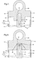
- Figure 3 is a cross sectional view of the damper assembly, showing the actuator impeding the flow of damping fluid through a piston aperture;
- Figure 4 is a cross sectional view of a connector and a damper having a slotted ring mount for receiving a connector;
- Figure 5 is a cross sectional view of a connector disposed within the cover of the damper assembly and in fluid communication with the inner bore of the piston rod;
- Figure 6 is a cross sectional view of a hollow rod connector disposed in the cover;
- Figure 7 is a cross sectional view of the piston rod showing an input passageway having a sealant extending downwardly;
- Figure 8 is a cross sectional view of the piston rod disposed within a cover showing two input passageways with a sealant extending downwardly;
- Figure 9 is a cross sectional view of a tennon style upper mount cover disposed on the piston rod;
- Figure 10 is a cross sectional view of the pneumatic connection system disposed within a strut;
- Figure 11 is a cross sectional view of the pneumatic connection system disposed within a strut showing the connector secured in place by a contoured nut and a clip fastener;
- Figure 12 is a cross sectional view of the pneumatic connection system disposed within a strut having an integral connector disposed in a nut holding the piston rod to the strut base;
- Figure 13 is a side view of a connector disposed on a ring style upper mount cover wherein the cover is disposed on the piston rod and a piston is disposed within a housing;
- Figure 14 is a side view of a connector disposed in the extension of a ring style upper mount cover showing the cover disposed on the piston rod and the piston rod disposed within the housing;
- Figure 15 is a side view of a tennon style upper mount cover disposed on a piston rod showing the piston rod disposed within a housing; and
- Figure 16 is a side view of the pneumatic connection system in a strut application.
-
- Referring to Figure 1, a damper assembly is generally shown at 10. In a first preferred embodiment, the
damper assembly 10 is a shock absorber. Thedamper assembly 10 includes ahousing 12 and astroking portion 13. Aconnector 15 is affixed to the bottom of thehousing 12. Anadditional connector 15A is affixed to the top of thestroking portion 13. As is known in the art of vehicle suspensions, theconnector 15 pivotally affixes thehousing 12 to abracket 11 on thesuspension system 17, andconnector 15A pivotally affixes thestroking portion 13 to thevehicle frame 19. - Referring to Figures 2 and 3, a cross-sectional view of the
damper assembly 10 is shown having apiston rod 14 defining aninner bore 16. Thepiston rod 14 is movably retained by thehousing 12, which has a damping fluid disposed therein. The piston rod 14 strokes into and out of thehousing 12 according to whether the distance between theframe 19 and thesuspension system 13 is increasing or decreasing due to such variables as rough road surfaces, potholes and unbalanced tires. - A
piston 18 is disposed at a firstdistal end 21 of thepiston rod 14 and strokes inside thehousing 12 along with thepiston rod 14. Thepiston 18 defines afirst chamber 22 and asecond chamber 24 within thehousing 12 wherein the damping fluid is disposed. Thepiston 18 includes at least oneaperture 26 for communicating damping fluid between the first 22 and second 24 chambers of thehousing 12. Anactuator 30 is disposed within thepiston 18 for varying the flow of the damping fluid through thepiston 18 between the first 22 and second 24 chambers within thehousing 12. - Referring to Figures 2 and 3, a
pin 25 is disposed within theactuator 30. Upon activating theactuator 30 with a pneumatic control signal, thepin 25 extends from theactuator 30 and obstructs theaperture 26 disposed within thepiston 18, thereby reducing the flow of the damping fluid through thepiston 18 between the first 22 and second 24 chambers within thehousing 12, as shown in Figure 3. By transmitting an opposite pneumatic control signal to theactuator 30, thepin 25 retracts opening theaperture 26 to permit damping fluid to flow freely through thepiston 18. - Referring to Figures 4 through 8, the
piston rod 14 further includes a strokingportion 13 at an end opposite from thepiston 18. The strokingportion 13 is disposed outside thehousing 12 and retains acover 60. A seal 34 (Figures 4-7) seals thecover 60 to thepiston rod 14 for retaining pneumatic air pressure within thepiston rod 14. Thecover 60 comprises a ring style upper mount utilized for securing theassembly 10 to thevehicle frame 19. - As shown in Figures 5, 6 and 8, the
cover 60 defines at least oneinput passageway 20 that is in fluid communication with theinner bore 16 of thepiston rod 14. In particular, referring to Figure 5, thecover 60 is a ring style upper mount having aslot 46 in a side of thecover 60 providing access for positioning aconnector 36 within thecover 60. Abushing 48 is disposed in thecover 60 for retaining theconnector 36 within thecover 60. Thebushing 48 also receives a pin (not shown) for connecting theassembly 10 to thevehicle frame 19. Theconnector 36 disposed in thecover 60 is adapted for receiving a coupling device (not shown) and defines theinput passageway 20 in fluid communication with theinner bore 16 of thepiston rod 14. The coupling device may be any type of pneumatic connector, such as a Schraeder Valve or a Quick Connect Coupling as described in U.S. Patent No. 4,867,487 to Phillis. Theassembly 10 of the subject invention further includes aflow restrictor 38 disposed in theinner passageway 20 for varying the pneumatic control signal communicated through theinner bore 16. - Referring to Figure 6, in another embodiment of the subject invention, the connector 36' is a hollow rod threaded into the
cover 60. Theseal 34 disposed between thecover 60 and thepiston rod 14 isolates the pneumatic air pressure inside thepiston rod 14 from environmental pressure. Aseal plate 40 is disposed in thecover 60 for maintaining the position of theseal 34. The flow restrictor 38 is disposed in theinner bore 16 for varying pneumatic control signals being communicated through theinner bore 16 and filtering pressure in thepiston 18. - The embodiments shown in Figures 7 and 8 are employed when the pneumatic pressure is routed through the
inner passageway 20 and inner bore 16 to thepiston 18 from acontrol chamber 42. Thecover 60 is secured to thepiston rod 14 and the strokingportion 13 extends over thehousing 12 to form thecontrol chamber 42. Thecontrol chamber 42 has aseal 44 disposed between thehousing 12 and the strokingportion 13 to maintain a control pressure within thecontrol chamber 42. Theconnector 36 is inserted through the strokingportion 13 andseal 44, and extends into thecontrol chamber 42 for communicating pneumatic signals into thecontrol chamber 42. As shown in Figure 7, theinner passageway 20 is disposed in thepiston rod 14 above theflow restrictor 38. Referring to Figure 8, a plurality ofinner passageways 20 are disposed in thecover 60 and terminate in acavity 61 above thepiston rod 14. Thecavity 61 communicates air pressure from thecontrol chamber 42 to theinner bore 16. - A further alternative embodiment is shown in Figure 9. Here, the
piston rod 14 is a tennon-style strut having a frustoconical tip and a threaded shaft. The strut defines theinput passageway 20 which is in fluid communication with theinner bore 16 for communicating pneumatic control signals. In addition, theflow restrictor 38 is disposed within theinner bore 16. - Referring to Figures 10, 11 and 12, the stroking
portion 13 comprises a strut having astrut base 50. Thehousing 12 extends into the strokingportion 13 and thepiston rod 14 is mounted to thestrut base 50. The embodiment shown in Figure 10 utilizes thesame connector 36 and flowrestrictor 38 as that shown in Figure 4. The embodiments shown in Figures 10 and 11 further include anut 52 threaded onto thepiston rod 14 between theconnector 36 and thestrut base 50. Thenut 52 secures thepiston rod 14 to thestrut base 50. Further included in the embodiments shown in Figures 10 and 11 is afastener 54 disposed around theconnector 36 and fastened to thenut 52 for securing thepiston rod 14 and theconnector 36 in operating position. Aseal 37 seals thepiston rod 14 to theconnector 36 preventing the pneumatic signal from being adversely affected by environmental pressure. - In the embodiment shown in Figure 11, the
fastener 54 comprises a clip fastener. Anadaptor 56 disposed between thenut 52 and thefastener 54 supports theconnector 36 within thestrut base 50. The embodiment shown in Figure 12 includes ahollow sleeve 58 partially received by theinner bore 16 of thepiston rod 14. Theadaptor 56 circumscribes that portion of thesleeve 58 not received by thebore 16 and is, thereby held in place. - Referring to Figures 13 through 16, side views of the embodiments discussed above are shown. Figure 13 is a full side view of the partial view shown in Figures 5 and 6. In particular, Figure 13 shows a side view of the
connector 36 disposed on the ring style upper mount cover 60 wherein thecover 60 is disposed on thepiston rod 14 and thepiston 18 is disposed within thehousing 12. Pneumatic pressure travels through thecover 60 and into thepiston rod 14, as shown in Figures 2 and 3. The air continues through the tube to the actuator, as discussed above. - Figure 14 is a full side view of the partial view shown in Figures 7 and 8. In particular, Figure 14 shows a side view of the connector 36' disposed on an extension of a ring style upper mount cover 60 wherein the
cover 60 is affixed to the end of thepiston rod 14 and thepiston rod 14 is disposed within thehousing 12. - Figure 15 is a full side view of the partial view shown in Figure 9. In particular, Figure 15 shows a side view of a tennon style upper mount cover 60 disposed on a
piston rod 14 having thepiston rod 14 disposed within ahousing 12. - Figure 16 is a full side view of the partial view shown in Figures 10, 11 and 12. In particular, Figure 16 shows a side view of a strut application wherein the
housing 12,cover 60,piston rod 14 andconnector 36 are inverted, and theconnector 36 is disposed in astrut base 50. - The invention has been described in an illustrative manner, and it is to be understood that the terminology which has been used is intended to be in the nature of words of description rather than of limitation.
- Obviously, many modifications and variations of the present invention are possible in light of the above teachings. It is, therefore, to be understood that within the scope of the appended claims, wherein reference numerals are merely for convenience and are not to be in any way limiting, the invention may be practiced otherwise than as specifically described. The invention may be practiced otherwise than as specifically described within the scope of the appended claims. In addition, the reference numerals in the claims are merely for convenience and are not to be read in any way as limiting.
Claims (17)
- A damper assembly (10) comprising:wherein said piston rod (14) defines an input passageway (20) being in fluid communication with said inner bore (16) for communicating pneumatic control signals to said actuator (30) and controlling said actuator (30).a housing (12) having a damping fluid disposed therein;a piston rod (14) having a rod defining an inner bore (16), wherein said piston rod (14) at least partially extends into said housing (12) and is movably disposed within said housing (12);a piston (18) disposed at a first distal end (21) of said piston rod (14) extending into said housing (12) to define a first chamber (22) and a second chamber (24) within said housing (12), wherein said piston (18) includes at least one aperture (26) for communicating said damping fluid between said first (22) and second (24) chambers of said housing (12);an actuator (30) disposed within said piston (18) for varying communication of said damping fluid through said piston (18) and between said first (22) and second (24) chambers within said housing (12);
- The assembly (10) of claim 1 wherein said piston rod (14) further includes a stroking portion (13) at an end opposite from said first distal end (21) having a cover (60) secured to said stroking portion (13).
- The assembly (10) of claim 2 including a seal (34) is disposed between said cover (60) and said piston rod (14) for maintaining pressure within said piston rod (14).
- The assembly (10) of claim 3 wherein said cover (60) defines at least one input passageway (20), said input passageway (20) being in fluid communication with said inner bore (16) of said piston rod (14).
- The assembly (10) of claim 4 including a connector (36) disposed in said cover (60) and adapted for receiving a coupling device, wherein said connector (36) defines said input passageway (20) and said input passageway (20) is in fluid communication with said inner bore (16) of said piston rod (14).
- The assembly (10) of claim 5 wherein said connector (36) is a hollow rod.
- The assembly (10) of claim 6 wherein said cover (60) is a ring style upper mount and said hollow rod (36) is disposed in said ring style upper mount.
- The assembly (10) of claim 7 including a seal plate (40) disposed in said cover (60) for maintaining said seal (34) in position.
- The assembly (10) of claim 3 said stroking portion (13) being secured to said piston rod (14) and extending over said housing to form a control chamber, and having a sealant disposed between said housing (12) and said stroking portion (13) to maintain a control pressure within said control chamber (42), wherein said connector (36) is disposed in said seal (44) extending to said control chamber (42) for communicating said pneumatic signal into said control chamber (42) and controlling said actuator (30).
- The assembly (10) of claim 9 wherein said cover (60) is a ring style upper mount having a slot (46) in a side of said ring style upper mount (60) for allowing said connector (36) to be positioned within said upper mount prior (60) to pressing in a bushing (48) for retaining said connector (36) within said upper mount (60).
- The assembly (10) of claim 9 wherein said stroking portion (13) is a strut having a strut base (50), said housing (12) extending into said strut (13) and said piston rod (14) mounted to said strut base (50).
- The assembly (10) of claim 11 including a nut (52) annularly disposed on said piston rod (14) between said connector (36) and said strut base (50) for securing said piston rod (14) to said strut base (50).
- The assembly (10) of claim 12 including a fastener (54) disposed around said connector (36) and fastened to said nut (52) for securing said piston rod (14) and connector (36) in position.
- The assembly (10) of claim 13 including an adaptor (56) disposed between said nut (52) and said fastener (54) for supporting said connector (36) within said strut base (50).
- The assembly (10) of claim 13 including a sleeve (58) annularly disposed around said inner bore (16) of said piston rod (14) for holding said adaptor (56) in position.
- The assembly (10) of claim 1 including a flow restrictor (38) disposed in said inner bore (16) for varying said pneumatic control signal being communicated through said inner bore (16).
- The assembly (10) of claim 1 including a flow restrictor (38) disposed in said input passageway (20) for varying said pneumatic control signal being communicated through said inner bore (16).
Applications Claiming Priority (2)
| Application Number | Priority Date | Filing Date | Title |
|---|---|---|---|
| US798138 | 2001-03-02 | ||
| US09/798,138 US6637555B2 (en) | 2001-03-02 | 2001-03-02 | Pneumatic connections for vehicle suspensions |
Publications (3)
| Publication Number | Publication Date |
|---|---|
| EP1236926A2 true EP1236926A2 (en) | 2002-09-04 |
| EP1236926A3 EP1236926A3 (en) | 2003-09-24 |
| EP1236926B1 EP1236926B1 (en) | 2006-12-20 |
Family
ID=25172634
Family Applications (1)
| Application Number | Title | Priority Date | Filing Date |
|---|---|---|---|
| EP02075557A Expired - Lifetime EP1236926B1 (en) | 2001-03-02 | 2002-02-11 | Pneumatic connections for vehicle suspensions |
Country Status (3)
| Country | Link |
|---|---|
| US (1) | US6637555B2 (en) |
| EP (1) | EP1236926B1 (en) |
| DE (1) | DE60216833T2 (en) |
Cited By (1)
| Publication number | Priority date | Publication date | Assignee | Title |
|---|---|---|---|---|
| US6637555B2 (en) * | 2001-03-02 | 2003-10-28 | Delphi Technologies, Inc. | Pneumatic connections for vehicle suspensions |
Families Citing this family (16)
| Publication number | Priority date | Publication date | Assignee | Title |
|---|---|---|---|---|
| US6592108B1 (en) * | 2002-07-18 | 2003-07-15 | Marc Schmidt-Thieme | Suspension device |
| US6955337B2 (en) * | 2003-04-03 | 2005-10-18 | Delphi Technologies, Inc. | Pneumatic module |
| DE10338939B3 (en) * | 2003-08-22 | 2005-02-03 | Continental Aktiengesellschaft | Pneumatic spring and damper unit for vehicle has overflow throttles in the cylinder housing between damper cavities |
| US20050173849A1 (en) * | 2004-02-10 | 2005-08-11 | Bart Vandewal | Electronically controlled frequency dependent damping |
| DE102004021586B4 (en) * | 2004-05-03 | 2010-09-23 | Continental Aktiengesellschaft | air spring |
| US7320387B2 (en) * | 2005-04-06 | 2008-01-22 | Arvinmeritor Technology, Llc | Load adaptive damper with transient air signal restrictor |
| US20070222127A1 (en) * | 2006-03-23 | 2007-09-27 | Landon Ball | Threaded Plate Single Shear Mount Shock Absorber/Strut Mount |
| US8869959B2 (en) | 2008-07-24 | 2014-10-28 | Fox Factory, Incorporated | Vehicle suspension damper |
| US9156325B2 (en) | 2008-03-19 | 2015-10-13 | Fox Factory, Inc. | Methods and apparatus for vehicle suspension having multiple gas volumes |
| US20100244340A1 (en) * | 2008-03-19 | 2010-09-30 | Wootten Dennis K | Methods and apparatus for combined variable damping and variable spring rate suspension |
| DE102010045114B4 (en) | 2010-09-13 | 2019-12-19 | Grammer Aktiengesellschaft | Method for operating a vehicle damping device for a vehicle seat / a vehicle cabin and vehicle damping device for a vehicle seat / a vehicle cabin |
| US8899560B2 (en) | 2011-02-16 | 2014-12-02 | Elite Suspension Systems, Llc | Springless combination shock absorber and suspension apparatus, and method of use |
| US9475354B1 (en) * | 2015-04-13 | 2016-10-25 | Reyco Granning, Llc | IFS including strut pivotally secured to chassis with clevis ring |
| US9676240B2 (en) * | 2015-04-13 | 2017-06-13 | Reyco Granning, Llc | IFS including control arm and strut supported by steering knuckle load arm |
| US10801593B2 (en) | 2017-04-26 | 2020-10-13 | Paratech, Incorporated | Strut extender mechanism |
| US11855379B2 (en) * | 2021-11-24 | 2023-12-26 | Caterpillar Inc. | Slidable nested conductors |
Citations (2)
| Publication number | Priority date | Publication date | Assignee | Title |
|---|---|---|---|---|
| US4886466A (en) | 1988-05-26 | 1989-12-12 | General Motors Corporation | Sealed electrical and pneumatic connector |
| US6007345A (en) | 1998-06-17 | 1999-12-28 | General Motors Corporation | Damper and electrical connection system |
Family Cites Families (30)
| Publication number | Priority date | Publication date | Assignee | Title |
|---|---|---|---|---|
| DE894965C (en) * | 1943-10-21 | 1953-10-29 | Hemscheidt Maschf Hermann | Vibration dampers, stabilizers or similar hydraulic devices connected between a sprung and an unsprung mass, especially for vehicles |
| US2698068A (en) * | 1950-11-10 | 1954-12-28 | Frank J Hein | Vehicle dive arrester |
| NL135634C (en) * | 1967-12-14 | |||
| US4022448A (en) * | 1975-12-05 | 1977-05-10 | Lehan James Reeder | Vehicle suspension unit and method of assembly thereof |
| IT1196653B (en) * | 1979-07-26 | 1988-11-25 | Fiat Auto Spa | OLEOPNEUMATIC SHOCK ABSORBER |
| US4465299A (en) * | 1982-11-30 | 1984-08-14 | Paccar Inc. | Vehicle suspension with load-controlled damping and load-controlled damper |
| JP2532059B2 (en) | 1985-09-13 | 1996-09-11 | 日産自動車株式会社 | Vehicle suspension control device |
| US4683992A (en) * | 1985-09-13 | 1987-08-04 | Ford Motor Company | Vehicle suspension damper with remote control |
| US4804203A (en) | 1987-11-27 | 1989-02-14 | Ford Motor Company | Control system and method for operating adjustable vehicular suspension unit over undulating road surfaces |
| US4867487A (en) | 1988-11-30 | 1989-09-19 | General Motors Corporation | Quick connect coupling |
| US5207300A (en) * | 1990-06-29 | 1993-05-04 | Boge Aktiengesellschaft | Hydraulic, adjustable vibration damper for motor vehicles |
| DE4129230A1 (en) * | 1990-09-14 | 1992-03-19 | Boge Ag | Adjustable shock absorber for vehicle - makes use of control surfaces subject to hydraulic and/or mechanical forces |
| US5097929A (en) * | 1991-02-19 | 1992-03-24 | Maremont Corporation | Adjustable shock absorber |
| US5190126A (en) * | 1991-09-16 | 1993-03-02 | Charles Curnutt | Shock absorber with air cavity controlled orifices |
| US5374077A (en) | 1993-01-11 | 1994-12-20 | Paccar Inc. | Pneumatically damped vehicle suspension system |
| US5655794A (en) | 1995-11-02 | 1997-08-12 | Ingersoll-Rand Company | Pneumatic connector |
| ES2150832B1 (en) | 1996-06-12 | 2001-06-16 | Fichtel & Sachs Ag | OPERATING DEVICE FOR THE OPERATION, IN PARTICULAR PNEUMATIC OPERATION, OF A FRICTION CLUTCH. |
| DE29610915U1 (en) | 1996-06-21 | 1996-08-29 | Hoerauf & Kohler Kg | Pneumatic damper |
| JPH1038007A (en) * | 1996-07-23 | 1998-02-13 | Kayaba Ind Co Ltd | Load sensitive type shock absorber |
| IT242443Y1 (en) * | 1996-11-13 | 2001-06-14 | Marzocchi Spa | HYDROPNEUMATIC SHOCK ABSORBER WITH DISTANCE ADJUSTMENT DEVICE. |
| US6082508A (en) | 1997-04-23 | 2000-07-04 | Honeywell International Inc. | Pneumatic damping strut |
| US5869754A (en) | 1997-07-28 | 1999-02-09 | Westinghouse Air Brake Company | Dual seal coupling apparatus for enabling quick measurement of brake cylinder pressure |
| US6126610A (en) | 1997-11-03 | 2000-10-03 | Novametrix Medical Systems, Inc. | Pneumatic connector with encoding |
| US6345706B1 (en) * | 1999-09-13 | 2002-02-12 | Delphi Technologies, Inc. | Electrical coupling assembly for a magnetorheological damper |
| IT1311114B1 (en) * | 1999-10-29 | 2002-02-28 | Sebac Italia Srl | SELF-REGULATING PNEUMATIC SUSPENSION FOR VEHICLES AND RELEVANT SHOCK ABSORBER. |
| US6379162B1 (en) * | 2000-07-27 | 2002-04-30 | Delphi Technologies, Inc. | Electrical connector system |
| US6405841B1 (en) * | 2000-09-15 | 2002-06-18 | Damon R. Zeno | Electromagnetic shock absorber |
| US6450304B1 (en) * | 2001-02-12 | 2002-09-17 | Delphi Technologies, Inc. | Piston and rod assembly for air-actuated variable damping |
| US6637555B2 (en) * | 2001-03-02 | 2003-10-28 | Delphi Technologies, Inc. | Pneumatic connections for vehicle suspensions |
| US6454060B1 (en) * | 2001-03-21 | 2002-09-24 | Delphi Technologies, Inc. | Vehicle suspension monotube strut base cup assembly |
-
2001
- 2001-03-02 US US09/798,138 patent/US6637555B2/en not_active Expired - Fee Related
-
2002
- 2002-02-11 DE DE60216833T patent/DE60216833T2/en not_active Expired - Lifetime
- 2002-02-11 EP EP02075557A patent/EP1236926B1/en not_active Expired - Lifetime
Patent Citations (2)
| Publication number | Priority date | Publication date | Assignee | Title |
|---|---|---|---|---|
| US4886466A (en) | 1988-05-26 | 1989-12-12 | General Motors Corporation | Sealed electrical and pneumatic connector |
| US6007345A (en) | 1998-06-17 | 1999-12-28 | General Motors Corporation | Damper and electrical connection system |
Cited By (1)
| Publication number | Priority date | Publication date | Assignee | Title |
|---|---|---|---|---|
| US6637555B2 (en) * | 2001-03-02 | 2003-10-28 | Delphi Technologies, Inc. | Pneumatic connections for vehicle suspensions |
Also Published As
| Publication number | Publication date |
|---|---|
| DE60216833D1 (en) | 2007-02-01 |
| US20020121731A1 (en) | 2002-09-05 |
| US6637555B2 (en) | 2003-10-28 |
| DE60216833T2 (en) | 2007-05-24 |
| EP1236926B1 (en) | 2006-12-20 |
| EP1236926A3 (en) | 2003-09-24 |
Similar Documents
| Publication | Publication Date | Title |
|---|---|---|
| EP1236926B1 (en) | Pneumatic connections for vehicle suspensions | |
| EP1544094B1 (en) | Front fork of motor cycle or the like | |
| JP4648321B2 (en) | Adjustable damper with control valve mounted on external collar | |
| US7213799B2 (en) | Pneumatic suspension and damping arrangement | |
| US5058868A (en) | Shock absorber with load compensation | |
| JPH11315876A (en) | Damper | |
| EP0193169B1 (en) | Air suspension | |
| US6135250A (en) | Hydropneumatic vibration damper of variable damping force | |
| JP2000046090A (en) | Spring seat fixing structure for hydraulic buffer | |
| US6817597B1 (en) | Spring-and-shock absorber system having differential roll bellows | |
| US6893033B2 (en) | Integrated air spring and strut | |
| WO2005032861A3 (en) | Booster to adapt air spring pressure for fdd shock absorber | |
| JP2001193782A (en) | Hydraulic shock absorber | |
| JPS6035810Y2 (en) | suspension system | |
| EP1375204B1 (en) | Piston rod seal for airlift damper | |
| KR102155661B1 (en) | Air suspension for vehicle | |
| JP4392221B2 (en) | Suspension device | |
| JP4130502B2 (en) | Hydraulic pipe coupling device for hydraulic shock absorber | |
| EP4086151A1 (en) | Oscillation system of the swingarm of a wheel with respect to the frame of a vehicle | |
| JP3938411B2 (en) | Hydraulic shock absorber | |
| JP4324424B2 (en) | Strut type shock absorber | |
| JPH08277098A (en) | Apparatus for forming hydraulic jack | |
| JP2020011613A (en) | Suspension device | |
| US20090020929A1 (en) | Strut Top Mount With Axial Hydraulic Element | |
| KR100448765B1 (en) | shock absorber of vehicle |
Legal Events
| Date | Code | Title | Description |
|---|---|---|---|
| PUAI | Public reference made under article 153(3) epc to a published international application that has entered the european phase |
Free format text: ORIGINAL CODE: 0009012 |
|
| AK | Designated contracting states |
Kind code of ref document: A2 Designated state(s): AT BE CH CY DE DK ES FI FR GB GR IE IT LI LU MC NL PT SE TR |
|
| AX | Request for extension of the european patent |
Free format text: AL;LT;LV;MK;RO;SI |
|
| PUAL | Search report despatched |
Free format text: ORIGINAL CODE: 0009013 |
|
| AK | Designated contracting states |
Kind code of ref document: A3 Designated state(s): AT BE CH CY DE DK ES FI FR GB GR IE IT LI LU MC NL PT SE TR |
|
| AX | Request for extension of the european patent |
Extension state: AL LT LV MK RO SI |
|
| 17P | Request for examination filed |
Effective date: 20040324 |
|
| AKX | Designation fees paid |
Designated state(s): DE FR GB IT |
|
| 17Q | First examination report despatched |
Effective date: 20040615 |
|
| GRAP | Despatch of communication of intention to grant a patent |
Free format text: ORIGINAL CODE: EPIDOSNIGR1 |
|
| GRAS | Grant fee paid |
Free format text: ORIGINAL CODE: EPIDOSNIGR3 |
|
| GRAA | (expected) grant |
Free format text: ORIGINAL CODE: 0009210 |
|
| AK | Designated contracting states |
Kind code of ref document: B1 Designated state(s): DE FR GB IT |
|
| PG25 | Lapsed in a contracting state [announced via postgrant information from national office to epo] |
Ref country code: IT Free format text: LAPSE BECAUSE OF FAILURE TO SUBMIT A TRANSLATION OF THE DESCRIPTION OR TO PAY THE FEE WITHIN THE PRE;WARNING: LAPSES OF ITALIAN PATENTS WITH EFFECTIVE DATE BEFORE 2007 MAY HAVE OCCURRED AT ANY TIME BEFORE 2007. THE CORRECT EFFECTIVE DATE MAY BE DIFFERENT FROM THE ONE RECORDED.SCRIBED TIME-LIMIT Effective date: 20061220 |
|
| REG | Reference to a national code |
Ref country code: GB Ref legal event code: FG4D |
|
| REF | Corresponds to: |
Ref document number: 60216833 Country of ref document: DE Date of ref document: 20070201 Kind code of ref document: P |
|
| ET | Fr: translation filed | ||
| PLBE | No opposition filed within time limit |
Free format text: ORIGINAL CODE: 0009261 |
|
| STAA | Information on the status of an ep patent application or granted ep patent |
Free format text: STATUS: NO OPPOSITION FILED WITHIN TIME LIMIT |
|
| 26N | No opposition filed |
Effective date: 20070921 |
|
| GBPC | Gb: european patent ceased through non-payment of renewal fee |
Effective date: 20070320 |
|
| PG25 | Lapsed in a contracting state [announced via postgrant information from national office to epo] |
Ref country code: GB Free format text: LAPSE BECAUSE OF NON-PAYMENT OF DUE FEES Effective date: 20070320 |
|
| PGFP | Annual fee paid to national office [announced via postgrant information from national office to epo] |
Ref country code: FR Payment date: 20100303 Year of fee payment: 9 |
|
| PGFP | Annual fee paid to national office [announced via postgrant information from national office to epo] |
Ref country code: DE Payment date: 20100226 Year of fee payment: 9 |
|
| REG | Reference to a national code |
Ref country code: FR Ref legal event code: ST Effective date: 20111102 |
|
| REG | Reference to a national code |
Ref country code: DE Ref legal event code: R119 Ref document number: 60216833 Country of ref document: DE Effective date: 20110901 |
|
| PG25 | Lapsed in a contracting state [announced via postgrant information from national office to epo] |
Ref country code: FR Free format text: LAPSE BECAUSE OF NON-PAYMENT OF DUE FEES Effective date: 20110228 |
|
| PG25 | Lapsed in a contracting state [announced via postgrant information from national office to epo] |
Ref country code: DE Free format text: LAPSE BECAUSE OF NON-PAYMENT OF DUE FEES Effective date: 20110901 |