EP1236889A2 - Apparatus and method for starting an engine - Google Patents
Apparatus and method for starting an engine Download PDFInfo
- Publication number
- EP1236889A2 EP1236889A2 EP02075620A EP02075620A EP1236889A2 EP 1236889 A2 EP1236889 A2 EP 1236889A2 EP 02075620 A EP02075620 A EP 02075620A EP 02075620 A EP02075620 A EP 02075620A EP 1236889 A2 EP1236889 A2 EP 1236889A2
- Authority
- EP
- European Patent Office
- Prior art keywords
- engine
- pulley
- crankshaft
- valve
- electric machine
- Prior art date
- Legal status (The legal status is an assumption and is not a legal conclusion. Google has not performed a legal analysis and makes no representation as to the accuracy of the status listed.)
- Withdrawn
Links
- 238000000034 method Methods 0.000 title claims abstract description 6
- 239000007858 starting material Substances 0.000 claims abstract description 62
- 230000006835 compression Effects 0.000 claims abstract description 21
- 238000007906 compression Methods 0.000 claims abstract description 21
- 230000009849 deactivation Effects 0.000 claims abstract description 18
- 238000002485 combustion reaction Methods 0.000 claims description 12
- 230000009467 reduction Effects 0.000 claims description 10
- RDYMFSUJUZBWLH-UHFFFAOYSA-N endosulfan Chemical compound C12COS(=O)OCC2C2(Cl)C(Cl)=C(Cl)C1(Cl)C2(Cl)Cl RDYMFSUJUZBWLH-UHFFFAOYSA-N 0.000 claims description 6
- 230000003213 activating effect Effects 0.000 claims 1
- 230000009977 dual effect Effects 0.000 description 6
- 230000033001 locomotion Effects 0.000 description 4
- 230000005540 biological transmission Effects 0.000 description 3
- 238000010276 construction Methods 0.000 description 3
- 230000005284 excitation Effects 0.000 description 3
- 239000000446 fuel Substances 0.000 description 3
- 230000001105 regulatory effect Effects 0.000 description 3
- 230000008901 benefit Effects 0.000 description 2
- 230000001276 controlling effect Effects 0.000 description 2
- 230000005355 Hall effect Effects 0.000 description 1
- 230000004913 activation Effects 0.000 description 1
- 230000000295 complement effect Effects 0.000 description 1
- 230000000694 effects Effects 0.000 description 1
- 230000005672 electromagnetic field Effects 0.000 description 1
- 230000004907 flux Effects 0.000 description 1
- 239000007789 gas Substances 0.000 description 1
- 238000009499 grossing Methods 0.000 description 1
- 230000003100 immobilizing effect Effects 0.000 description 1
- 238000004519 manufacturing process Methods 0.000 description 1
- 239000000463 material Substances 0.000 description 1
- 238000012986 modification Methods 0.000 description 1
- 230000004048 modification Effects 0.000 description 1
- 239000010705 motor oil Substances 0.000 description 1
- 230000010349 pulsation Effects 0.000 description 1
- 238000005086 pumping Methods 0.000 description 1
- 230000004044 response Effects 0.000 description 1
- 238000011144 upstream manufacturing Methods 0.000 description 1
Images



Classifications
-
- F—MECHANICAL ENGINEERING; LIGHTING; HEATING; WEAPONS; BLASTING
- F02—COMBUSTION ENGINES; HOT-GAS OR COMBUSTION-PRODUCT ENGINE PLANTS
- F02N—STARTING OF COMBUSTION ENGINES; STARTING AIDS FOR SUCH ENGINES, NOT OTHERWISE PROVIDED FOR
- F02N15/00—Other power-operated starting apparatus; Component parts, details, or accessories, not provided for in, or of interest apart from groups F02N5/00 - F02N13/00
- F02N15/02—Gearing between starting-engines and started engines; Engagement or disengagement thereof
- F02N15/08—Gearing between starting-engines and started engines; Engagement or disengagement thereof the gearing being of friction type
-
- F—MECHANICAL ENGINEERING; LIGHTING; HEATING; WEAPONS; BLASTING
- F01—MACHINES OR ENGINES IN GENERAL; ENGINE PLANTS IN GENERAL; STEAM ENGINES
- F01L—CYCLICALLY OPERATING VALVES FOR MACHINES OR ENGINES
- F01L1/00—Valve-gear or valve arrangements, e.g. lift-valve gear
- F01L1/34—Valve-gear or valve arrangements, e.g. lift-valve gear characterised by the provision of means for changing the timing of the valves without changing the duration of opening and without affecting the magnitude of the valve lift
-
- F—MECHANICAL ENGINEERING; LIGHTING; HEATING; WEAPONS; BLASTING
- F01—MACHINES OR ENGINES IN GENERAL; ENGINE PLANTS IN GENERAL; STEAM ENGINES
- F01L—CYCLICALLY OPERATING VALVES FOR MACHINES OR ENGINES
- F01L1/00—Valve-gear or valve arrangements, e.g. lift-valve gear
- F01L1/46—Component parts, details, or accessories, not provided for in preceding subgroups
-
- F—MECHANICAL ENGINEERING; LIGHTING; HEATING; WEAPONS; BLASTING
- F01—MACHINES OR ENGINES IN GENERAL; ENGINE PLANTS IN GENERAL; STEAM ENGINES
- F01L—CYCLICALLY OPERATING VALVES FOR MACHINES OR ENGINES
- F01L13/00—Modifications of valve-gear to facilitate reversing, braking, starting, changing compression ratio, or other specific operations
- F01L13/0005—Deactivating valves
-
- F—MECHANICAL ENGINEERING; LIGHTING; HEATING; WEAPONS; BLASTING
- F01—MACHINES OR ENGINES IN GENERAL; ENGINE PLANTS IN GENERAL; STEAM ENGINES
- F01L—CYCLICALLY OPERATING VALVES FOR MACHINES OR ENGINES
- F01L13/00—Modifications of valve-gear to facilitate reversing, braking, starting, changing compression ratio, or other specific operations
- F01L13/08—Modifications of valve-gear to facilitate reversing, braking, starting, changing compression ratio, or other specific operations for decompression, e.g. during starting; for changing compression ratio
-
- F—MECHANICAL ENGINEERING; LIGHTING; HEATING; WEAPONS; BLASTING
- F02—COMBUSTION ENGINES; HOT-GAS OR COMBUSTION-PRODUCT ENGINE PLANTS
- F02D—CONTROLLING COMBUSTION ENGINES
- F02D41/00—Electrical control of supply of combustible mixture or its constituents
- F02D41/008—Controlling each cylinder individually
- F02D41/0087—Selective cylinder activation, i.e. partial cylinder operation
-
- F—MECHANICAL ENGINEERING; LIGHTING; HEATING; WEAPONS; BLASTING
- F02—COMBUSTION ENGINES; HOT-GAS OR COMBUSTION-PRODUCT ENGINE PLANTS
- F02N—STARTING OF COMBUSTION ENGINES; STARTING AIDS FOR SUCH ENGINES, NOT OTHERWISE PROVIDED FOR
- F02N11/00—Starting of engines by means of electric motors
- F02N11/04—Starting of engines by means of electric motors the motors being associated with current generators
-
- F—MECHANICAL ENGINEERING; LIGHTING; HEATING; WEAPONS; BLASTING
- F02—COMBUSTION ENGINES; HOT-GAS OR COMBUSTION-PRODUCT ENGINE PLANTS
- F02N—STARTING OF COMBUSTION ENGINES; STARTING AIDS FOR SUCH ENGINES, NOT OTHERWISE PROVIDED FOR
- F02N19/00—Starting aids for combustion engines, not otherwise provided for
- F02N19/004—Aiding engine start by using decompression means or variable valve actuation
-
- F—MECHANICAL ENGINEERING; LIGHTING; HEATING; WEAPONS; BLASTING
- F01—MACHINES OR ENGINES IN GENERAL; ENGINE PLANTS IN GENERAL; STEAM ENGINES
- F01L—CYCLICALLY OPERATING VALVES FOR MACHINES OR ENGINES
- F01L2800/00—Methods of operation using a variable valve timing mechanism
- F01L2800/01—Starting
-
- F—MECHANICAL ENGINEERING; LIGHTING; HEATING; WEAPONS; BLASTING
- F16—ENGINEERING ELEMENTS AND UNITS; GENERAL MEASURES FOR PRODUCING AND MAINTAINING EFFECTIVE FUNCTIONING OF MACHINES OR INSTALLATIONS; THERMAL INSULATION IN GENERAL
- F16H—GEARING
- F16H7/00—Gearings for conveying rotary motion by endless flexible members
- F16H7/08—Means for varying tension of belts, ropes or chains
- F16H2007/0802—Actuators for final output members
- F16H2007/0806—Compression coil springs
-
- F—MECHANICAL ENGINEERING; LIGHTING; HEATING; WEAPONS; BLASTING
- F16—ENGINEERING ELEMENTS AND UNITS; GENERAL MEASURES FOR PRODUCING AND MAINTAINING EFFECTIVE FUNCTIONING OF MACHINES OR INSTALLATIONS; THERMAL INSULATION IN GENERAL
- F16H—GEARING
- F16H7/00—Gearings for conveying rotary motion by endless flexible members
- F16H7/08—Means for varying tension of belts, ropes or chains
- F16H2007/0802—Actuators for final output members
- F16H2007/0823—Electric actuators
-
- F—MECHANICAL ENGINEERING; LIGHTING; HEATING; WEAPONS; BLASTING
- F16—ENGINEERING ELEMENTS AND UNITS; GENERAL MEASURES FOR PRODUCING AND MAINTAINING EFFECTIVE FUNCTIONING OF MACHINES OR INSTALLATIONS; THERMAL INSULATION IN GENERAL
- F16H—GEARING
- F16H7/00—Gearings for conveying rotary motion by endless flexible members
- F16H7/08—Means for varying tension of belts, ropes or chains
- F16H2007/0863—Finally actuated members, e.g. constructional details thereof
- F16H2007/0874—Two or more finally actuated members
-
- F—MECHANICAL ENGINEERING; LIGHTING; HEATING; WEAPONS; BLASTING
- F16—ENGINEERING ELEMENTS AND UNITS; GENERAL MEASURES FOR PRODUCING AND MAINTAINING EFFECTIVE FUNCTIONING OF MACHINES OR INSTALLATIONS; THERMAL INSULATION IN GENERAL
- F16H—GEARING
- F16H7/00—Gearings for conveying rotary motion by endless flexible members
- F16H7/08—Means for varying tension of belts, ropes or chains
- F16H2007/0876—Control or adjustment of actuators
- F16H2007/0887—Control or adjustment of actuators the tension being a function of load
Definitions
- the present invention relates to an apparatus and method for starting an internal combustion engine.
- a typical internal combustion engine includes both a starter motor and a generator.
- the starter motor provides an engine cranking force to the flywheel of the engine in order to rotate the crankshaft and facilitate the movement of the pistons prior to the ignition of the engine.
- the generator provides an electrical output in order to meet the vehicle loads as well as the charge the vehicle's battery. Generally, a rotational force is applied to a pulley of the generator in order to provide an electrical charge from the generator.
- a dual function starter generator for starting the engine and for generating current for the electrical needs of the vehicle, the combination starting motor arrangement and generator cooperates with the engine during both initial starting and various running modes of the vehicle and engine.
- a motor vehicle has an internal combustion engine, a transmission, and a flywheel arranged between the engine and transmission for equalizing the non-uniformities of engine output torque.
- the generator which normally is spacially and functionally separate from the electric starter, is combined in the present invention with the starter so as to form one structural unit. Moreover, the combined generator and starter is built into, and operates in conjunction with, a compression reduction system or valve deactivation system for reducing the required forces necessary for driving the crankshaft of the engine in order to start the engine.
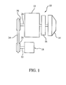
- the vehicle proposed system includes an internal combustion engine 12, a transmission 14, a flywheel 16, and a starter generator 18.
- starter generator 18 performs the dual functions of providing an engine cranking force in order to start the internal combustion engine, as well as generating an electrical output in response to a rotational force received from engine 12 via a belt 24.
- Prior ignition systems utilized two separate components, a starter motor and a generator, in order to provide the functions now provided by starter generator 18 of the present application.
- starter generator 18 provides the necessary force to start the engine.
- a valve deactivation system is enabled to provide a compression release in order to lower the amount of torque that must be provided by starter generator 18 in order to start the vehicle engine.
- Starter generator 18 has a pulley 20 secured to a shaft 22. Shaft 22 is mounted for rotation within housing of starter generator 18. A belt 24 is positioned to transfer forces between pulley 20 and a pulley 26 of engine 12. Pulley 26 is secured to a crankshaft 28 which is rotated in accordance with a rotational force provided by internal combustion engine 12. Accordingly, starter generator 18 and the valve deactivation system of an exemplary embodiment can be used with most current engine designs. Thus, starter generator 18 can be placed in the position typically used for an automobile generator. Therefore, there are no complicated design changes required for implementation of the method and apparatus disclosed herein.
- Starter generator 18 is provided with switching electronics that allow starter generator 18 to either provide a rotational force to pulley 20 or convert a rotational force received from pulley 20 into an electrical output.
- starter generator 18 is equipped with, among other elements, a rotor assembly, a stator, and a rectifier bridge necessary to provide a charging circuit, an excitation circuit, and a pre-excitation circuit in order to produce an electrical source.
- starter generator 18 can be equipped with alternative means for producing an electrical current as a rotational force is applied to pulley 20.
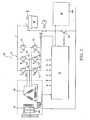
- a three-phase rotary machine comprising an alternator proper, a control, a rectifier bridge 30, and a unit 32 for controlling bridge 30.
- Starter generator 18 includes a coil-carrying rotor 34 constituting the primary magnetic circuit associated with two rings and with two brushes that convey excitation current (of the order of a few amps); and a stator 36 carrying a plurality of coils constituting the secondary magnetic circuit, connected in star or delta configuration in the common case of a three-phase structure and acting, during alternator operation, to deliver converted electrical power to the rectifier bridge 30 (several tens of amps at a voltage of the same order as the battery voltage).
- Bridge 30 is connected to the various phases of the secondary magnetic circuit 36 and is connected between ground and a power supply terminal of a battery 38 of a vehicle (not shown). It is constituted by a plurality of diodes 40 forming a rectifier bridge, and also by a plurality of switches such as transistors 42 that are connected in parallel with respective diodes 40 and which control the various phases of the alternator.
- the diodes act as freewheel diodes, whereas in generator mode, they act as a rectifier bridge.
- Transistors 42 are advantageously MOSFET type transistors. It will be observed that said transistors include, by construction, a diode between drain and source. Consequently they enable the rectifier and phase control bridge 30 to be implemented using transistor components only which then act both as switches and as freewheel diodes.
- the motor mode operation of the alternator is achieved by imposing DC on the primary magnetic circuit 34 and by delivering signals that are phase-shifted by 120° to the phases of the stator, which signals are ideally sinewave signals, but may optionally be squarewave signals or trapezoidal wave signals.
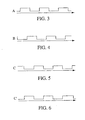
- FIG. 3-6 an example of a control sequence for the switches constituted by transistors 42 is illustrated.
- the sequence is made up of squarewave signals issued by the control unit.
- the signals A, B, and C shown in these figures are control signals for those of the transistors 42 in the bridge 30 which are connected to ground.
- the signals A', B', and C' which control the other transistors, i.e. those connected to the battery, are signals that are inverted relative to the signals A, B, and C, without overlapping them.
- the rotor performs one full revolution while each of the phases goes through a number of periods equal to the number of pairs of poles of the rotor (e.g. eight).
- This motor operation is used for driving the engine of the vehicle in order to start it, thereby making it possible, in comparison with conventional vehicles, to eliminate the starter and the associated drive ring, and also the power cabling generally associated with the starter.
- control signals for transistors 42 are advantageously variable frequency signals, at a frequency which is regulated to be increasing by unit 32, so as to avoid any slip of the rotor relative to the rotating magnetic field created by the stator.
- frequency regulation may be provided by unit 32 in such a manner so as to guarantee that the alternator has a speed profile enabling the engine to be started.
- control unit 32 includes a means for recognizing a code signal that authorizes engine starting. This signal is transmitted to the unit 32 by a code transmitter means inside the vehicle. The unit 32 switches on the transistors 42 in a manner suitable for starting the engine only if it receives the code signal. Consequently, the control unit 32 and the code transmitter means which transmit the unlocking signal to said unit, constitute a system for immobilizing the engine.
- unit 32 controls the transistors 42 so as to operate in alternator mode.
- unit 32 controls the transistors 42 so that all of them are open circuit across the terminals of all of the diodes.
- the bridge 32 then reverts to being a conventional rectifier bridge.
- the transistors 42 are controlled so as to short circuit the conductive diodes. They are caused to be open circuit only across the terminals of non-conductive diodes.
- unit 32 is connected to a means for detecting when diodes 40 pass from one state to another.
- these means may be constituted by a sensor, such as a Hall effect sensor, for measuring the angular position of the rotor relative to the stator.
- Such a sensor may also be used for determining the speed of the rotor, e.g. by counting pulses in a given time window, so as to enable the unit to detect that the engine has started and thus switch from operating in motor mode to operating in generator mode.
- means 44 are provided for regulating voltage so as to maintain the battery voltage at a suitable level.
- a switch 46 e.g. another MOSFET type switch, whose ON or OFF state is controlled by the control unit. This switch is designed to short circuit the regulator in motor mode so that the secondary magnetic circuit 36 is then directly excited by the battery voltage.
- the new device is belt driven similarly to an alternator of an automobile and driven off the accessory drive of the automobile engine.
- a valve deactivation system is enabled to provide a compression release keeping the exhaust valves open for the first few engine cranking revolutions of a cold start until the starter motor overcomes the sheer force of the cold, possibly waxed, engine oil, and the cranking rpm is sufficient for successful engine starting.
- starter generator 18 does not need to provide a high torque force to pulley 26.
- a compression limiting system is enabled for the first few engine cranking revolutions of a cold start, thus easing the load on said generator.
- FIG. 7 a valve deactivation system utilizing a solenoid coil is illustrated.
- a portion of an overhead cam type internal combustion engine having a cylinder block defining a cylinder (not shown), the cylinder block including a cylinder head 50 with a passage 52 therein, which may be an intake or exhaust passage, terminating at a port 54 encircled by a valve seat 56, that opens into the cylinder.
- Flow through the port 54 is controlled by a poppet valve 58 having a head 60 with a seat 62 thereon for seating against the valve seat 56 and a valve stem 64 slidably supported in a valve guide bore 66, which in the construction shown is formed in a valve guide 68 suitably fixed in the cylinder head 50.
- a valve return spring 70 bears at its upper end against a tubular, spring retainer 72 secured to the upper end of the valve stem 64 by split locks 74 engaged in the groove 75 of the valve stem 64 in a conventional manner.
- An engine driven camshaft 76 having at least one cam 78 thereon, is rotatably supported in a conventional manner, not shown, at a predetermined distance above the upper end of the valve stem 64 to normally control the movement of the poppet valve 58 between a valve closed position, as shown in Figure 7, and a valve open position relative to the valve seat 56.
- a solenoid coil 80 will be continuously energized, as controlled by the electronic control unit, not shown, so that an electromagnetic field whose flux path passes through the opposed working surfaces of the flanges 82 and 84 (pole piece and armature, respectively) will cause the valve actuator to be magnetically coupled to the cam follower 86, so that during reciprocation of the cam follower by cam 78, the valve actuator 88 will also be reciprocated accordingly to control the opening and closing movement of the poppet valve.
- the solenoid coil when energized, can generate the required electromagnetic force at relatively low power, to operatively maintain the cam follower and valve actuator electromagnetically connected together.
- the solenoid coil is deenergized, preferably as when this poppet valve 58 is in a valve closed position. This, in effect, will then uncouple the cam follower from the valve actuator so that the cam follower is free to reciprocate relative to the then stationary valve actuator, with the spring 90 still maintaining the cam follower 86 in operative engagement with the cam.
- this bias force of spring 90 will still be less than the bias force of the valve return spring 70, whereby the poppet valve will remain in its valve closed position and, accordingly, this poppet valve is thus deactivated.
- the solenoid coil 80 can be again energized at any time as desired, but valve operation will only occur after the cam follower 86 again engages the base circle of the cam 78 so that the interface between the opposed working surfaces of the flanges 82 and 84 is again affected, whereby the cam follower 86 and valve actuator 88 will again be electromagnetically coupled together.
- solenoid 50, cam follower 86, and valve actuator 88 are configured such that once solenoid 50 is energized, port 54 is opened, and thus the compression in the valve chamber is reduced.
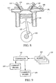
- a cylinder of a multi-cylinder, four-stroke cycle reciprocating internal combustion engine has crankshaft 100 with connecting rod 102 and piston 104.
- Exhaust gases exit the cylinder through exhaust port 112 after flowing past exhaust valve 114.
- Exhaust valve 114 is operated by exhaust camshaft 116.
- the ingress and egress of air into and out of the engine can be controlled by adjusting the timing of intake camshaft 118 and exhaust camshaft 116, respectively.
- timing of intake camshaft 118 and exhaust camshaft 116 will affect the cylinder pressures as piston 104 is moved by rod 102.
- timing of the intake and exhaust camshafts are adjusted to result in significant overlap near the top of the piston stroke, compression will be reduced as a portion of the air charge escapes into the exhaust and intake manifolds.
- Figure 8 illustrates an engine having a dual overhead camshaft.
- a single overhead cam may be used to adjust the timing of both intake valve 110 and exhaust valve 114 in the same direction. Dual independent phasing can be achieved by two phasers on two camshafts.
- FIG 9 illustrates a control system 120 for operating a cam phaser.
- Controller 122 receives a variety of inputs from engine operating sensors 124 which include many of the types of sensors known to those skilled in the art of engine control. Accordingly, sensors 124 may include engine speed, engine lead, intake manifold absolute pressure, engine intake air mass flow rate, engine temperature, vehicle speed, vehicle gear selection, throttle position, accelerator position, and other parameters known to those skilled in the art.
- Controller 122 which may comprise an electronic engine operating controller drawn from many of the types known to those skilled in the art of automotive electronic engine controllers, is connected with camshaft phaser 126.
- a single camshaft phaser is required when using a single overhead cam to actuate both intake valve 110 and exhaust valve 114.
- a second camshaft phaser 128 may be required.
- both camshafts may be linked together with one phaser.
- Controller 122 compares sensed operating parameters with predetermined threshold values. For example, in a typical control algorithm, cylinder deactivation would not be used unless engine speed exceeds a minimum threshold value, and engine load is less than a minimum threshold value. In this sense, the term “exceed” is used herein to mean that the value of the sensed parameter may either be greater than or less than the threshold value. In the event that sensed parameters exceed threshold values, controller 122 will command camshaft phasers 126 and 128 to move to adjust or shift the timing of camshafts 118 and 116 which operate intake valve 110 and exhaust valve 114, respectively.
- the pressure within the chamber may be minimized through a means for detecting the position of the piston within the cylinder when the starter generator completes the stop phase of the engine. This would minimize the pressure peak within the chamber permitting the start of the engine during cold start, i.e. the valve could be put at the right position. For example, stopping the crankshaft a few degrees after top dead-center of the right cylinder enables the next starter cycle because rotational energy of this piston assembly enhances the ease of the starting of the engine.
- starter generator 18 provides a dual function (e.g. engine starting and current generating). During the engine starting function, a cylinder compression reduction system or valve deactivation system is utilized to reduce the necessary torque to drive a pulley connected to the engine crankshaft.
- Engine control module 200 receives inputs from a plurality of sensors located throughout the vehicle in order to provide ECM 200 with a current vehicle status. Accordingly, and if the vehicle has been determined to be in an engine off mode and an operator is attempting to start the engine, ECM 200 will activate the compression reduction system in addition to placing starter generator 18 into a motor operating mode.
- the engine control module deactivates the compression reduction system, enables fuel (and spark, if spark ignition engine), starts the engine, and converts the starter generator into a generator mode.
- starter generator 18 to have the size and weight roughly the same as current alternator designs.
- crankshaft of the engine is driven through the frictional engagement of belt 24 which is configured to wrap around pulley 26 and pulley 20, thus allowing starter generator 18 to perform an engine cranking duty without making any significant changes to the current engine design.
- starter generator 18 which allows the engine to be constructed without a separate starter motor and complementary ring gear for the engine flywheel.
- the overall mass of the engine is reduced as there is no need for a starter motor, and through the use of a compression reduction system, the size of starter generator 18 can be kept relatively small.
- the smoothing out of the port pulsations in engine will be achieved much faster than an engine system that utilizes a flywheel and starter motor combination.
Landscapes
- Engineering & Computer Science (AREA)
- Mechanical Engineering (AREA)
- General Engineering & Computer Science (AREA)
- Chemical & Material Sciences (AREA)
- Combustion & Propulsion (AREA)
- Devices For Conveying Motion By Means Of Endless Flexible Members (AREA)
- Output Control And Ontrol Of Special Type Engine (AREA)
- Connection Of Motors, Electrical Generators, Mechanical Devices, And The Like (AREA)
Abstract
Description
- The present invention relates to an apparatus and method for starting an internal combustion engine.
- Increased fuel efficiency has been a primary goal of most vehicle designs. In addition, and in order to meet this goal, vehicle designs have been implemented in order to provide a more efficient vehicle without having to sacrifice passenger comfort and satisfaction.
- A typical internal combustion engine includes both a starter motor and a generator. The starter motor provides an engine cranking force to the flywheel of the engine in order to rotate the crankshaft and facilitate the movement of the pistons prior to the ignition of the engine.
- The generator provides an electrical output in order to meet the vehicle loads as well as the charge the vehicle's battery. Generally, a rotational force is applied to a pulley of the generator in order to provide an electrical charge from the generator.
- A dual function starter generator for starting the engine and for generating current for the electrical needs of the vehicle, the combination starting motor arrangement and generator cooperates with the engine during both initial starting and various running modes of the vehicle and engine.
- More particularly, a motor vehicle has an internal combustion engine, a transmission, and a flywheel arranged between the engine and transmission for equalizing the non-uniformities of engine output torque.
- The generator, which normally is spacially and functionally separate from the electric starter, is combined in the present invention with the starter so as to form one structural unit. Moreover, the combined generator and starter is built into, and operates in conjunction with, a compression reduction system or valve deactivation system for reducing the required forces necessary for driving the crankshaft of the engine in order to start the engine.
- The above-described and other features and advantages of the present invention will be appreciated and understood by those skilled in the art from the following detailed description, drawings, and appended claims.
-
- Figure 1 is a schematic illustration of a vehicle propulsion system having a starter generator motor;
- Figure 2 is a schematic illustration of portions of a starter generator motor;
- Figures 3-6 illustrate a control sequence for motor operation of the starter generator illustrated in figure 2;
- Figure 7 is a schematic illustration of a cylinder deactivation system;
- Figures 8 and 9 illustrate an alternative cylinder deactivation system;
- Figures 10 and 11 illustrate a starter generator motor; and
- Figures 12 and 13 illustrate an engine control module for operating the starter generator motor and the valve deactivation system.
-
- Referring now to Figure 1, a
vehicle propulsion system 10 is illustrated schematically. The vehicle proposed system includes aninternal combustion engine 12, atransmission 14, aflywheel 16, and astarter generator 18. In accordance with an exemplary embodiment of the present invention,starter generator 18 performs the dual functions of providing an engine cranking force in order to start the internal combustion engine, as well as generating an electrical output in response to a rotational force received fromengine 12 via abelt 24. - Prior ignition systems utilized two separate components, a starter motor and a generator, in order to provide the functions now provided by
starter generator 18 of the present application. Here,starter generator 18 provides the necessary force to start the engine. In addition, and during the same starting function, a valve deactivation system is enabled to provide a compression release in order to lower the amount of torque that must be provided bystarter generator 18 in order to start the vehicle engine. -
Starter generator 18 has apulley 20 secured to ashaft 22.Shaft 22 is mounted for rotation within housing ofstarter generator 18. Abelt 24 is positioned to transfer forces betweenpulley 20 and apulley 26 ofengine 12. Pulley 26 is secured to acrankshaft 28 which is rotated in accordance with a rotational force provided byinternal combustion engine 12. Accordingly,starter generator 18 and the valve deactivation system of an exemplary embodiment can be used with most current engine designs. Thus,starter generator 18 can be placed in the position typically used for an automobile generator. Therefore, there are no complicated design changes required for implementation of the method and apparatus disclosed herein. -
Starter generator 18 is provided with switching electronics that allowstarter generator 18 to either provide a rotational force to pulley 20 or convert a rotational force received frompulley 20 into an electrical output. In order to perform the latter,starter generator 18 is equipped with, among other elements, a rotor assembly, a stator, and a rectifier bridge necessary to provide a charging circuit, an excitation circuit, and a pre-excitation circuit in order to produce an electrical source. Of course, and as applications may require,starter generator 18 can be equipped with alternative means for producing an electrical current as a rotational force is applied topulley 20. - Referring now to Figure 2, portions of
starter generator 18 are shown. A three-phase rotary machine is shown comprising an alternator proper, a control, arectifier bridge 30, and aunit 32 for controllingbridge 30. -
Starter generator 18 includes a coil-carryingrotor 34 constituting the primary magnetic circuit associated with two rings and with two brushes that convey excitation current (of the order of a few amps); and astator 36 carrying a plurality of coils constituting the secondary magnetic circuit, connected in star or delta configuration in the common case of a three-phase structure and acting, during alternator operation, to deliver converted electrical power to the rectifier bridge 30 (several tens of amps at a voltage of the same order as the battery voltage). -
Bridge 30 is connected to the various phases of the secondarymagnetic circuit 36 and is connected between ground and a power supply terminal of a battery 38 of a vehicle (not shown). It is constituted by a plurality ofdiodes 40 forming a rectifier bridge, and also by a plurality of switches such astransistors 42 that are connected in parallel withrespective diodes 40 and which control the various phases of the alternator. - In motor mode, the diodes act as freewheel diodes, whereas in generator mode, they act as a rectifier bridge.
-
Transistors 42 are advantageously MOSFET type transistors. It will be observed that said transistors include, by construction, a diode between drain and source. Consequently they enable the rectifier andphase control bridge 30 to be implemented using transistor components only which then act both as switches and as freewheel diodes. - The motor mode operation of the alternator is achieved by imposing DC on the primary
magnetic circuit 34 and by delivering signals that are phase-shifted by 120° to the phases of the stator, which signals are ideally sinewave signals, but may optionally be squarewave signals or trapezoidal wave signals. - Referring now to Figures 3-6, an example of a control sequence for the switches constituted by
transistors 42 is illustrated. The sequence is made up of squarewave signals issued by the control unit. The signals A, B, and C shown in these figures are control signals for those of thetransistors 42 in thebridge 30 which are connected to ground. The signals A', B', and C' which control the other transistors, i.e. those connected to the battery, are signals that are inverted relative to the signals A, B, and C, without overlapping them. - This is shown in Figure 6 where the signal C' is drawn for controlling the transistor connected to the transistor controlled by the signal C.
- With this kind of control, the rotor performs one full revolution while each of the phases goes through a number of periods equal to the number of pairs of poles of the rotor (e.g. eight).
- This motor operation is used for driving the engine of the vehicle in order to start it, thereby making it possible, in comparison with conventional vehicles, to eliminate the starter and the associated drive ring, and also the power cabling generally associated with the starter.
- To enable the engine to be started in this way, the control signals for
transistors 42 are advantageously variable frequency signals, at a frequency which is regulated to be increasing byunit 32, so as to avoid any slip of the rotor relative to the rotating magnetic field created by the stator. - For example, frequency regulation may be provided by
unit 32 in such a manner so as to guarantee that the alternator has a speed profile enabling the engine to be started. - In accordance with the invention, the
control unit 32 includes a means for recognizing a code signal that authorizes engine starting. This signal is transmitted to theunit 32 by a code transmitter means inside the vehicle. Theunit 32 switches on thetransistors 42 in a manner suitable for starting the engine only if it receives the code signal. Consequently, thecontrol unit 32 and the code transmitter means which transmit the unlocking signal to said unit, constitute a system for immobilizing the engine. - Immediately after the engine has started,
unit 32 controls thetransistors 42 so as to operate in alternator mode. - To this end, in an implementation of the invention,
unit 32 controls thetransistors 42 so that all of them are open circuit across the terminals of all of the diodes. - The
bridge 32 then reverts to being a conventional rectifier bridge. - In another possible embodiment, the
transistors 42 are controlled so as to short circuit the conductive diodes. They are caused to be open circuit only across the terminals of non-conductive diodes. - Thus, a current no longer passes through the conductive diodes, such that the short circuits made in this way serve to reduce losses.
- To synchronize control of
transistors 42 relative to the switching from the conductive state to the non-conductive state ofdiodes 40,unit 32 is connected to a means for detecting whendiodes 40 pass from one state to another. By way of example, these means may be constituted by a sensor, such as a Hall effect sensor, for measuring the angular position of the rotor relative to the stator. - Such a sensor may also be used for determining the speed of the rotor, e.g. by counting pulses in a given time window, so as to enable the unit to detect that the engine has started and thus switch from operating in motor mode to operating in generator mode.
- Also, and in a manner that is likewise known, means 44 are provided for regulating voltage so as to maintain the battery voltage at a suitable level.
- Provision is also made for a
switch 46, e.g. another MOSFET type switch, whose ON or OFF state is controlled by the control unit. This switch is designed to short circuit the regulator in motor mode so that the secondarymagnetic circuit 36 is then directly excited by the battery voltage. - Thus, and when
starter generator 18 is in its starter mode, wherein a rotational force is applied topulley 20 fromstarter generator 18, a resultant force is applied topulley 26.Pulley 26 rotates the crankshaft of the internal combustion engine in order to facilitate the starting of the same. - The functions of the starting motor and the alternator have been combined into one unit. Thus, the need for a cranking motor has been eliminated. Accordingly, there is a resultant cost and weight savings in the construction of the vehicle.
- In an exemplary embodiment, the new device is belt driven similarly to an alternator of an automobile and driven off the accessory drive of the automobile engine.
- In addition, and when
starter generator 18 is operated in its starter mode, a valve deactivation system is enabled to provide a compression release keeping the exhaust valves open for the first few engine cranking revolutions of a cold start until the starter motor overcomes the sheer force of the cold, possibly waxed, engine oil, and the cranking rpm is sufficient for successful engine starting. Thus,starter generator 18 does not need to provide a high torque force topulley 26. In addition, and whenstarter generator 18 is operated in its starter mode, a compression limiting system is enabled for the first few engine cranking revolutions of a cold start, thus easing the load on said generator. - Referring now to Figure 7, a valve deactivation system utilizing a solenoid coil is illustrated. As illustrated, a portion of an overhead cam type internal combustion engine having a cylinder block defining a cylinder (not shown), the cylinder block including a
cylinder head 50 with apassage 52 therein, which may be an intake or exhaust passage, terminating at a port 54 encircled by avalve seat 56, that opens into the cylinder. - Flow through the port 54 is controlled by a
poppet valve 58 having ahead 60 with aseat 62 thereon for seating against thevalve seat 56 and avalve stem 64 slidably supported in a valve guide bore 66, which in the construction shown is formed in avalve guide 68 suitably fixed in thecylinder head 50. - A
valve return spring 70 bears at its upper end against a tubular, spring retainer 72 secured to the upper end of thevalve stem 64 bysplit locks 74 engaged in thegroove 75 of thevalve stem 64 in a conventional manner. - An engine driven
camshaft 76, having at least onecam 78 thereon, is rotatably supported in a conventional manner, not shown, at a predetermined distance above the upper end of thevalve stem 64 to normally control the movement of thepoppet valve 58 between a valve closed position, as shown in Figure 7, and a valve open position relative to thevalve seat 56. - During normal engine operation, a solenoid coil 80 will be continuously energized, as controlled by the electronic control unit, not shown, so that an electromagnetic field whose flux path passes through the opposed working surfaces of the
flanges 82 and 84 (pole piece and armature, respectively) will cause the valve actuator to be magnetically coupled to thecam follower 86, so that during reciprocation of the cam follower bycam 78, thevalve actuator 88 will also be reciprocated accordingly to control the opening and closing movement of the poppet valve. - Because
spring 90 is operative to bias theflanges - However, when it is desired to deactivate the
poppet valve 58, the solenoid coil is deenergized, preferably as when thispoppet valve 58 is in a valve closed position. This, in effect, will then uncouple the cam follower from the valve actuator so that the cam follower is free to reciprocate relative to the then stationary valve actuator, with thespring 90 still maintaining thecam follower 86 in operative engagement with the cam. However, even during reciprocation of thecam follower 86 in a downward direction, with reference to Figure 7, so as to compress thespring 90, this bias force ofspring 90 will still be less than the bias force of thevalve return spring 70, whereby the poppet valve will remain in its valve closed position and, accordingly, this poppet valve is thus deactivated. - If the poppet valve is to be made operative again, the solenoid coil 80 can be again energized at any time as desired, but valve operation will only occur after the
cam follower 86 again engages the base circle of thecam 78 so that the interface between the opposed working surfaces of theflanges cam follower 86 andvalve actuator 88 will again be electromagnetically coupled together. - Alternatively,
solenoid 50,cam follower 86, andvalve actuator 88 are configured such that oncesolenoid 50 is energized, port 54 is opened, and thus the compression in the valve chamber is reduced. - Referring now to Figure 8, an alternative means for cylinder deactivation is illustrated. A cylinder of a multi-cylinder, four-stroke cycle reciprocating internal combustion engine has crankshaft 100 with connecting
rod 102 andpiston 104. Air that has been regulated bythrottle 106, located upstream of the cylinder, flows into the cylinder throughintake port 108 which is controlled byintake valve 110. Exhaust gases exit the cylinder throughexhaust port 112 after flowingpast exhaust valve 114.Exhaust valve 114 is operated byexhaust camshaft 116. The ingress and egress of air into and out of the engine can be controlled by adjusting the timing ofintake camshaft 118 andexhaust camshaft 116, respectively. The adjustment of timing ofintake camshaft 118 andexhaust camshaft 116 will affect the cylinder pressures aspiston 104 is moved byrod 102. When the timing of the intake and exhaust camshafts are adjusted to result in significant overlap near the top of the piston stroke, compression will be reduced as a portion of the air charge escapes into the exhaust and intake manifolds. - It is noted that Figure 8 illustrates an engine having a dual overhead camshaft. However, as will be apparent to those skilled in the art, and in view of the present invention, a single overhead cam may be used to adjust the timing of both
intake valve 110 andexhaust valve 114 in the same direction. Dual independent phasing can be achieved by two phasers on two camshafts. - Figure 9 illustrates a
control system 120 for operating a cam phaser.Controller 122 receives a variety of inputs fromengine operating sensors 124 which include many of the types of sensors known to those skilled in the art of engine control. Accordingly,sensors 124 may include engine speed, engine lead, intake manifold absolute pressure, engine intake air mass flow rate, engine temperature, vehicle speed, vehicle gear selection, throttle position, accelerator position, and other parameters known to those skilled in the art. -
Controller 122, which may comprise an electronic engine operating controller drawn from many of the types known to those skilled in the art of automotive electronic engine controllers, is connected withcamshaft phaser 126. A single camshaft phaser is required when using a single overhead cam to actuate bothintake valve 110 andexhaust valve 114. However, in the case of a dual overhead cam, asecond camshaft phaser 128 may be required. Alternatively, both camshafts may be linked together with one phaser. -
Controller 122 compares sensed operating parameters with predetermined threshold values. For example, in a typical control algorithm, cylinder deactivation would not be used unless engine speed exceeds a minimum threshold value, and engine load is less than a minimum threshold value. In this sense, the term "exceed" is used herein to mean that the value of the sensed parameter may either be greater than or less than the threshold value. In the event that sensed parameters exceed threshold values,controller 122 will commandcamshaft phasers camshafts intake valve 110 andexhaust valve 114, respectively. - In yet another embodiment, the pressure within the chamber may be minimized through a means for detecting the position of the piston within the cylinder when the starter generator completes the stop phase of the engine. This would minimize the pressure peak within the chamber permitting the start of the engine during cold start, i.e. the valve could be put at the right position. For example, stopping the crankshaft a few degrees after top dead-center of the right cylinder enables the next starter cycle because rotational energy of this piston assembly enhances the ease of the starting of the engine.
- Accordingly, and in accordance with an exemplary embodiment of the present invention,
starter generator 18 provides a dual function (e.g. engine starting and current generating). During the engine starting function, a cylinder compression reduction system or valve deactivation system is utilized to reduce the necessary torque to drive a pulley connected to the engine crankshaft. - Activation of the
starter generator 18 and the compression reduction system is facilitated through the use of an engine control module 200 (Figures 12 and 13).Engine control module 200 receives inputs from a plurality of sensors located throughout the vehicle in order to provideECM 200 with a current vehicle status. Accordingly, and if the vehicle has been determined to be in an engine off mode and an operator is attempting to start the engine,ECM 200 will activate the compression reduction system in addition to placingstarter generator 18 into a motor operating mode. - Once the engine achieves sufficient cranking RPM's, which is confirmed by inputs perceived by
ECM 200, the engine control module deactivates the compression reduction system, enables fuel (and spark, if spark ignition engine), starts the engine, and converts the starter generator into a generator mode. - The use of the system allows
starter generator 18 to have the size and weight roughly the same as current alternator designs. In addition, the crankshaft of the engine is driven through the frictional engagement ofbelt 24 which is configured to wrap aroundpulley 26 andpulley 20, thus allowingstarter generator 18 to perform an engine cranking duty without making any significant changes to the current engine design. - Accordingly, manufacturing costs are reduced through the use of
starter generator 18 which allows the engine to be constructed without a separate starter motor and complementary ring gear for the engine flywheel. In addition, the overall mass of the engine is reduced as there is no need for a starter motor, and through the use of a compression reduction system, the size ofstarter generator 18 can be kept relatively small. - Moreover, and since the
starter generator 18 is much smaller than a flywheel and starter motor combination, the smoothing out of the port pulsations in engine will be achieved much faster than an engine system that utilizes a flywheel and starter motor combination. - Other alternative embodiments include electromagnetic valve train actuation or other means of individual valve motion control which would result in an exhaust valve deactivation, i.e., in a four-cylinder engine - open two valves, in a six-cylinder engine - open three valves, etc. This allows the starter generator to start a vehicle during cold start in the temperature range of -20 degrees Celsius without compressing the captured air.
- The valve opening reduces the pressure into the cylinder chambers of the engine as such a work required to start engine would be reduced, w=(f/a)dx, where a is the face area of the piston. Fuel economy will be improved by taking advantage of the stop and start function provided by the starter generator when this takes place, and pumping losses of the engine will be reduced from operation of a cylinder deactivation system.
- While the invention has been described with reference to a preferred embodiment, it will be understood by those skilled in the art that various changes may be made and equivalents may be substituted for elements thereof without departing from the scope of the invention. In addition, many modifications may be made to adapt a particular situation or material to the teachings of the invention without departing from the essential scope thereof. Therefore, it is intended that the invention not be limited to the particular embodiment disclosed as the best mode contemplated for carrying out this invention, but that the invention will include all embodiments falling within the scope of the appended claims. Accordingly, it is to be understood that the present invention has been described by way of illustration and not limitation.
Claims (18)
- An apparatus for starting an engine (12), comprising:a) a starter generator (18) being configured to provide a rotational force to a pulley (20) and receive a rotational force to said pulley, said starter generator generating a current when said pulley receives said rotational force;b) a belt (24) being configured, dimensioned and positioned to frictionally engage said pulley of said starter generator and a crankshaft pulley (26) of said engine, said crankshaft pulley being fixedly secured to a crankshaft (28) of said engine; andc) a valve deactivation system (120) for opening an exhaust valve (114) in a cylinder of said engine.
- The apparatus as in claim 1, further comprising:d) an engine control module (200) for activating said starter generator and said valve deactivation system, said engine control module being configured to receive a plurality of inputs from a plurality of sensors (124), said plurality of sensors providing information about the status of said engine and an engine ignition protocol.
- The apparatus as in claim 2, wherein said engine control module controls operations of a vehicle.
- The apparatus as in claim 1,wherein said valve deactivation system includes a solenoid (80) being configured, dimensioned and positioned to manipulate said exhaust valve between an open position and a closed position, said open position causing the compression in said cylinder to decrease.
- The apparatus as in claim 1, wherein said valve deactivation system includes a hydraulically operated valve, said valve being configured, dimensioned, and positioned to move within a range defined by an open position and a closed position, said open position causing the compression in said cylinder to decrease.
- The apparatus as in claim 1, wherein said current is large enough to meet all of the electrical requirements of a vehicle.
- A method for starting an internal combustion engine of a vehicle, comprising:a) deactivating a valve of a cylinder of said engine; andb) rotating a crankshaft of said engine, said crankshaft being rotated by a belt coupled to an electrical device capable of generating an electrical current when said engine is running, said crankshaft of said engine being rotated by said belt until said engine begins to run.
- The method as in claim 7, wherein said crankshaft is capable of being rotated by a first rotational force generated by said electric device when said valve of said cylinder is deactivated, said first force being less than the force required to rotate said crankshaft when said valve is not deactivated.
- An apparatus for starting an engine of a vehicle, comprising:a) an electric machine (18) being configured to provide a rotational force to a pulley (20) and receive a rotational force to said pulley, said electric machine generating power when said pulley receives said rotational force;b) a belt (24) for frictionally engaging said pulley of said electric machine and a crankshaft pulley of said engine, said crankshaft pulley being fixedly secured to a crankshaft (28) of said engine; andc) a compression limiting system (120) for limiting the compression of a cylinder of said engine when said electric machine rotates said crankshaft.
- An apparatus as in claim 9, wherein said electric machine is configured and dimensioned to be positioned at a location similar to a generator for an internal combustion engine for a vehicle.
- An apparatus as in claim 9, wherein said electric machine further comprises a housing being secured to said engine.
- An apparatus as in claim 11, wherein said belt also provides a driving force to a fan of said engine.
- An apparatus as in claim 11, wherein said belt provides the driving force for all of the belt driven by terms of said engine and said vehicle.
- An apparatus as in claim 9, wherein said electric machine further comprises a rotor assembly (34) fixedly secured to a shaft mounted for rotation within said electric machine, said shaft being fixedly secured to said pulley.
- An apparatus for starting an internal combustion engine of a vehicle, comprising:a) an electric machine (18) being mounted to said engine, said electric machine being configured to provide a rotational force to a pulley (20) of said electric machine and being configured to receive and generate a current when a rotational force is applied to said pulley by said engine;b) a belt (24) being configured, dimensioned, and positioned to frictionally engage said pulley of said electric machine and a crankshaft pulley (26) of said engine, said crankshaft pulley being fixedly secured to a crankshaft (28) of said engine; andc) a compression reduction system for reducing the compression in said engine when said electric machine provides a rotational force to said crankshaft pulley.
- The apparatus as in claim 15, wherein said compression reduction system opens an exhaust valve (114) in a cylinder of said engine.
- The apparatus as in claim 15, wherein said compression reduction system further comprises a cam phaser (126).
- The apparatus as in claim 15, wherein said compression reduction system and said electric machine are controlled by an engine control module (200).
Applications Claiming Priority (2)
| Application Number | Priority Date | Filing Date | Title |
|---|---|---|---|
| US273191 | 1999-03-19 | ||
| US27319101P | 2001-03-02 | 2001-03-02 |
Publications (2)
| Publication Number | Publication Date |
|---|---|
| EP1236889A2 true EP1236889A2 (en) | 2002-09-04 |
| EP1236889A3 EP1236889A3 (en) | 2006-05-03 |
Family
ID=23042890
Family Applications (1)
| Application Number | Title | Priority Date | Filing Date |
|---|---|---|---|
| EP02075620A Withdrawn EP1236889A3 (en) | 2001-03-02 | 2002-02-15 | Apparatus and method for starting an engine |
Country Status (2)
| Country | Link |
|---|---|
| US (4) | US20020123401A1 (en) |
| EP (1) | EP1236889A3 (en) |
Cited By (5)
| Publication number | Priority date | Publication date | Assignee | Title |
|---|---|---|---|---|
| WO2008116703A1 (en) * | 2007-03-23 | 2008-10-02 | Schaeffler Kg | Valve drive of an internal combustion engine |
| CN103481886A (en) * | 2012-05-04 | 2014-01-01 | 福特环球技术公司 | Methods and systems for transitioning between driveline braking modes |
| CN104228825A (en) * | 2013-06-10 | 2014-12-24 | 福特环球技术公司 | method for operating a vehicle |
| CN106605362A (en) * | 2014-08-29 | 2017-04-26 | 艾默生环境优化技术有限公司 | Variable speed compressor control with lost rotor mitigation |
| EP3306073A3 (en) * | 2016-09-28 | 2018-05-02 | Yamaha Hatsudoki Kabushiki Kaisha | Straddled vehicle |
Families Citing this family (79)
| Publication number | Priority date | Publication date | Assignee | Title |
|---|---|---|---|---|
| US6978753B2 (en) * | 2001-09-14 | 2005-12-27 | Bg Products, Inc. | Automated combustion chamber decarboning squid |
| DE10219695A1 (en) * | 2002-05-02 | 2003-11-20 | Daimler Chrysler Ag | Drive system for a motor vehicle with an electric machine |
| KR100456852B1 (en) * | 2002-09-05 | 2004-11-10 | 현대자동차주식회사 | Electrical system of a vehicle |
| US6856032B2 (en) * | 2002-10-24 | 2005-02-15 | Dana Corporation | Starter/alternator assembly of internal combustion engine and method for controlling thereof |
| EP1557932A1 (en) * | 2002-10-28 | 2005-07-27 | Toyota Jidosha Kabushiki Kaisha | Generator-motor |
| US7411324B2 (en) * | 2002-10-28 | 2008-08-12 | Toyota Jidosha Kabushiki Kaisha | Generator-motor |
| FR2847960B1 (en) * | 2002-12-03 | 2005-11-04 | Hutchinson | TRANSMISSION SYSTEM COMPRISING AN INTERNAL COMBUSTION ENGINE AND AN ALTERNOMETER. |
| JP2004211572A (en) * | 2002-12-27 | 2004-07-29 | Denso Corp | Belt-driven engine starter |
| DE10314727A1 (en) * | 2003-03-31 | 2004-10-28 | Robert Bosch Gmbh | Tensioning belt drive from vehicle engine to electrical machine operating as generator or motor, employs tensioning component operating on first strand |
| US6987330B2 (en) * | 2003-04-16 | 2006-01-17 | Ford Global Technologies, Llc | Method and system for controlling a belt-driven integrated starter generator |
| DE10322540A1 (en) * | 2003-05-19 | 2004-12-23 | Siemens Ag | Belt drive in the drive train of a motor vehicle and method for controlling such a belt drive |
| JP4239723B2 (en) * | 2003-07-24 | 2009-03-18 | トヨタ自動車株式会社 | A drive system including a generator motor and a computer-readable recording medium storing a program for causing a computer to control the generator motor |
| US6834631B1 (en) * | 2004-03-08 | 2004-12-28 | Dana Corporation | Method of determining transition from starter to alternator function by monitoring belt tension or tensioner position |
| DE102004025936A1 (en) * | 2004-05-27 | 2005-12-22 | Ina-Schaeffler Kg | Belt drive for an internal combustion engine |
| DE102005017038A1 (en) * | 2005-04-13 | 2006-10-19 | Schaeffler Kg | Traction drive, in particular belt drive for ancillaries of an internal combustion engine |
| WO2007002651A2 (en) * | 2005-06-27 | 2007-01-04 | Metaldyne Company, Llc | Gear-driven balance shaft apparatus with backlash control |
| US7434640B2 (en) * | 2005-07-27 | 2008-10-14 | Eaton Corporation | Method for reducing torque required to crank engine in hybrid vehicle |
| US7627941B2 (en) * | 2005-10-26 | 2009-12-08 | Hamilton Sundstrand Corporation | Fixture for aligning motor assembly |
| US7239032B1 (en) * | 2005-11-18 | 2007-07-03 | Polaris Industries Inc. | Starter-generator |
| US7443142B2 (en) * | 2005-12-21 | 2008-10-28 | Temic Automotive Of North America, Inc. | Active rectification of alternator output without using a position sensor |
| US7271570B2 (en) * | 2005-12-21 | 2007-09-18 | Temic Automotive Of North America, Inc. | Active rectification of alternator output without using a position sensor |
| US7671067B2 (en) * | 2006-02-09 | 2010-03-02 | Enzon Pharmaceuticals, Inc. | Treatment of non-hodgkin's lymphomas with multi-arm polymeric conjugates of 7-ethyl-10-hydroxycamtothecin |
| US7462627B2 (en) * | 2006-02-09 | 2008-12-09 | Enzon Pharmaceuticals, Inc. | Multi-arm polymeric conjugates of 7-ethyl-10-hydroxycamptothecin for treatment of breast, colorectal, pancreatic, ovarian and lung cancers |
| MX2009008549A (en) * | 2007-02-09 | 2009-08-18 | Enzon Pharmaceuticals Inc | Treatment of resistant or refractory cancers with multi-arm polymeric conjugates of 7-ethyl-10-hydroxycamptothecin. |
| US7847523B2 (en) * | 2008-02-22 | 2010-12-07 | Continental Automotive Systems, Inc. | Systems and methods for optimizing the operation of a generator |
| US7870926B2 (en) * | 2008-05-14 | 2011-01-18 | Honda Motor Company, Ltd. | Vehicles including jack shaft having clutch and coupling engine and front wheel |
| TW201010732A (en) * | 2008-08-29 | 2010-03-16 | Enzon Pharmaceuticals Inc | Method of treating RAS associated cancer |
| US20100098654A1 (en) * | 2008-10-21 | 2010-04-22 | Fabio Pastorino | Treatment of neuroblastoma with multi-arm polymeric conjugates of 7-ethyl-10-hydroxycamptothecin |
| EP2184494A3 (en) * | 2008-11-05 | 2016-09-21 | Magna Powertrain Inc. | On-demand on-off water pump assembly |
| US20100316506A1 (en) * | 2009-06-11 | 2010-12-16 | Gm Global Technology Operations, Inc. | Engine fuel pump drive system |
| DE102009045880A1 (en) * | 2009-10-21 | 2011-11-17 | Robert Bosch Gmbh | Method and device for operating a belt drive of a motor vehicle |
| US9151366B2 (en) * | 2010-09-10 | 2015-10-06 | Litens Automotive Partnership | Intelligent belt drive system and method |
| US20120152644A1 (en) * | 2010-12-20 | 2012-06-21 | Paul Harriman Kydd | Compliant, balanced belt or chain drive |
| US9334932B2 (en) * | 2011-05-13 | 2016-05-10 | Litens Automotive Partnership | Intelligent belt drive system and method |
| US9464697B2 (en) | 2011-09-05 | 2016-10-11 | Litens Automotive Partnership | Intelligent belt drive system and method |
| DE102012205146A1 (en) * | 2012-03-29 | 2013-10-02 | Bayerische Motoren Werke Aktiengesellschaft | Belt drive for operatively connecting initiator generator with crankshaft of e.g. petrol engine for motor car, has traction unit wrapped around driving wheels, where force is transferred from one wheel to another wheel in regenerative mode |
| WO2013159181A1 (en) * | 2012-04-28 | 2013-10-31 | Litens Automotive Partnership | Adjustable tensioner |
| US9322380B2 (en) | 2012-05-04 | 2016-04-26 | Ford Global Technologies, Llc | Methods and systems for engine starting during a shift |
| US9039570B2 (en) | 2012-05-04 | 2015-05-26 | Ford Global Technologies, Llc | Methods and systems for adjusting driveline disconnect clutch operation |
| US9068546B2 (en) * | 2012-05-04 | 2015-06-30 | Ford Global Technologies, Llc | Methods and systems for engine cranking |
| US9115682B2 (en) | 2012-05-04 | 2015-08-25 | Ford Global Technologies, Llc | Methods and systems for operating a driveline disconnect clutch |
| US9278692B2 (en) | 2012-05-04 | 2016-03-08 | Ford Global Technologies, Llc | Methods and systems for a four wheel drive vehicle driveline |
| US9108614B2 (en) | 2012-05-04 | 2015-08-18 | Ford Global Technologies, Llc | Methods and systems for adapting a driveline disconnect clutch transfer function |
| US8818600B2 (en) | 2012-05-04 | 2014-08-26 | Ford Global Technologies, Llc | Methods and systems for adjusting driveline operation during an accelerator tip-out |
| DE102013104516A1 (en) * | 2012-05-04 | 2013-11-07 | Ford Global Technologies, Llc | Method for starting engine of hybrid vehicle system, involves starting rotation of stopped engine, if predicted desired rotational torque is larger than swelling deer moment amount according to gearbox upshift |
| US8932179B2 (en) | 2012-05-04 | 2015-01-13 | Ford Global Technologies, Llc | Methods and systems for transitioning between braking modes |
| US8998771B2 (en) | 2012-05-04 | 2015-04-07 | Ford Global Technologies, Llc | Methods and systems for a vehicle driveline |
| US8965616B2 (en) | 2012-05-04 | 2015-02-24 | Ford Global Technologies, Llc | Methods and systems for reducing gear lash noise |
| US9650036B2 (en) | 2012-05-04 | 2017-05-16 | Ford Global Technologies, Llc | Methods and systems for adjusting cylinder air charge |
| US9156469B2 (en) | 2012-05-04 | 2015-10-13 | Ford Global Technologies, Llc | Methods and systems for a driveline disconnect clutch |
| US9447747B2 (en) | 2012-05-04 | 2016-09-20 | Ford Global Technologies, Llc | Methods and systems for stopping an engine |
| US9656665B2 (en) | 2012-05-04 | 2017-05-23 | Ford Global Technologies, Llc | Methods and systems for a driveline dual mass flywheel |
| US8977449B2 (en) | 2012-05-04 | 2015-03-10 | Ford Global Technologies, Llc | Methods and systems for holding a vehicle stopped on a hill |
| US9108632B2 (en) | 2012-05-04 | 2015-08-18 | Ford Global Technologies, Llc | Methods and systems for operating a driveline clutch |
| DE102012217206A1 (en) * | 2012-09-24 | 2014-03-27 | Schaeffler Technologies Gmbh & Co. Kg | Clamping device for a traction mechanism drive |
| DE112014001387B4 (en) * | 2013-03-15 | 2017-07-20 | Remy Technologies Llc | Generator / engine start arrangement with a gear reduction system |
| KR101405235B1 (en) * | 2013-07-18 | 2014-06-19 | 현대자동차 주식회사 | Hydraulic timing chain tensioner and timing chain system |
| JP5986617B2 (en) * | 2013-12-17 | 2016-09-06 | 株式会社デンソー | Transmission system |
| US20150300462A1 (en) * | 2014-02-06 | 2015-10-22 | Gates Corporation | Tensioner |
| US9140338B2 (en) * | 2014-02-06 | 2015-09-22 | Gates Corporation | Tensioner |
| US9920819B2 (en) * | 2014-02-06 | 2018-03-20 | Gates Corporation | Tensioner |
| GB2523080A (en) * | 2014-02-12 | 2015-08-19 | Ford Global Tech Llc | An apparatus and method for starting an engine |
| US9657705B2 (en) * | 2014-03-13 | 2017-05-23 | GM Global Technology Operations LLC | Powertrain for a vehicle and an electromechanical apparatus coupleable to an engine |
| US9481236B2 (en) | 2014-03-13 | 2016-11-01 | GM Global Technology Operations LLC | Powertrain for a vehicle |
| DE102014217455B4 (en) * | 2014-09-02 | 2016-12-01 | Robert Bosch Gmbh | A method of starting an internal combustion engine by a belt-driven starter generator |
| US10125677B1 (en) * | 2014-10-06 | 2018-11-13 | Raymond C. Sherry | Engine mount for easy installation and removal of engine |
| US9759293B2 (en) * | 2014-10-21 | 2017-09-12 | Litens Automotive Partnership | Endless drive arrangement and improved two-armed tensioning system for same |
| EP3253996B1 (en) | 2015-02-06 | 2021-10-20 | Litens Automotive Partnership | Endless drive arrangement for hybrid vehicle using two-armed tensioner with non-orbiting arms |
| US9528576B2 (en) * | 2015-04-14 | 2016-12-27 | Deere & Company | Drive system with hydraulic idler tensioner |
| CN109219714B (en) * | 2016-05-30 | 2021-10-15 | 利滕斯汽车合伙公司 | Continuous drives and tensioning systems for continuous drives |
| WO2018102542A1 (en) | 2016-11-30 | 2018-06-07 | Cummins Inc. | Compression release valvetrain design |
| DE102017110192B3 (en) * | 2017-05-11 | 2018-10-31 | Schaeffler Technologies AG & Co. KG | Method for detecting belt slippage |
| US11261945B1 (en) * | 2017-06-22 | 2022-03-01 | Board Of Trustees Of The University Of Alabama, For And On Behalf Of The University Of Alabama In Huntsville | Coupling system for reducing fatigue and dynamic amplification of loads in objects |
| US10774906B2 (en) | 2018-03-27 | 2020-09-15 | Gates Corporation | Tensioner |
| CN108831277B (en) * | 2018-08-23 | 2024-05-14 | 南京工业职业技术学院 | Multifunctional engine teaching bench |
| EP4001695A1 (en) * | 2020-11-20 | 2022-05-25 | Manuel Lindner | Automatic adjustment and monitoring of a belt drive |
| EP4056407B1 (en) | 2021-03-12 | 2025-05-07 | Schaeffler Technologies AG & Co. KG | A control device, a method and drivetrain system for controlling components of the drivetrain system of a vehicle |
| CN114776503A (en) * | 2022-03-31 | 2022-07-22 | 东风汽车集团股份有限公司 | Engine system and vehicle |
| US20240344595A1 (en) * | 2023-04-11 | 2024-10-17 | Fca Us Llc | Dual arm tensioner with hydraulic strut |
Family Cites Families (37)
| Publication number | Priority date | Publication date | Assignee | Title |
|---|---|---|---|---|
| US3673884A (en) * | 1970-11-16 | 1972-07-04 | Bombardier Ltd | Chain tensioning device for snowmobile type transmission |
| DE2925675A1 (en) | 1979-06-26 | 1981-02-12 | Volkswagenwerk Ag | MOTOR VEHICLE |
| US4699097A (en) | 1984-08-31 | 1987-10-13 | Mazda Motor Corporation | Means for suppressing engine output torque fluctuations |
| JPS63201306A (en) * | 1987-02-17 | 1988-08-19 | Komatsu Ltd | Variable valve timing valve train |
| US4711207A (en) | 1987-04-07 | 1987-12-08 | General Motors Corporation | Valve deactivator mechanism |
| US4758208A (en) | 1987-07-13 | 1988-07-19 | General Motors Corporation | Automatic belt tensioner for vehicle combined starter-generator |
| US4862009A (en) | 1988-03-22 | 1989-08-29 | General Electric Company | Combined electric starter and alternator system using a permanent magnet synchronous machine |
| US4822321A (en) | 1988-07-18 | 1989-04-18 | General Motors Corporation | Combination water pump and belt tensioner |
| US5132604A (en) | 1989-04-04 | 1992-07-21 | Honda Giken Kogyo Kabushiki Kaisha | Engine starter and electric generator system |
| US5126582A (en) | 1989-08-23 | 1992-06-30 | Mitsubishi Denki K.K. | Combined engine starter/generator |
| US5103127A (en) | 1991-02-25 | 1992-04-07 | General Motors Corporation | Torque converter mounted starter/generator for a motor vehicle |
| US5176581A (en) | 1991-06-06 | 1993-01-05 | Kumm Industries, Inc. | Self-energized controllable belt tensioner |
| JP2615296B2 (en) | 1991-12-10 | 1997-05-28 | 三ツ星ベルト株式会社 | Power transmission mechanism |
| US5327856A (en) | 1992-12-22 | 1994-07-12 | General Motors Corporation | Method and apparatus for electrically driving engine valves |
| JP2750800B2 (en) * | 1992-12-24 | 1998-05-13 | 株式会社ユニシアジェックス | Intake valve control device for internal combustion engine |
| US5418400A (en) | 1993-12-27 | 1995-05-23 | Ford Motor Company | Integrated generator and starter motor |
| US6011377A (en) | 1994-03-01 | 2000-01-04 | Hamilton Sundstrand Corporation | Switched reluctance starter/generator system and method of controlling same |
| US5524725A (en) | 1994-07-01 | 1996-06-11 | Arctco, Inc. | Automatic chain tension adjustor |
| US5467748A (en) | 1995-03-16 | 1995-11-21 | Ford Motor Company | Internal combustion engine with intake port throttling and exhaust camshaft phase shifting for cylinder deactivation |
| US5613918A (en) | 1995-04-06 | 1997-03-25 | Fleischman; Daniel G. | Bidirectional torque responsive belt tensioner |
| JP3640431B2 (en) * | 1995-05-18 | 2005-04-20 | 本田技研工業株式会社 | Outboard engine |
| JPH0949408A (en) * | 1995-08-07 | 1997-02-18 | Sanshin Ind Co Ltd | Outboard motor with auto decompression device |
| US5642703A (en) | 1995-10-16 | 1997-07-01 | Ford Motor Company | Internal combustion engine with intake and exhaust camshaft phase shifting for cylinder deactivation |
| FR2745445B1 (en) | 1996-02-28 | 1998-05-07 | Valeo Electronique | VEHICLE ALTERNATOR USED AS A GENERATOR AND AN ELECTRIC MOTOR FOR STARTING THE VEHICLE'S INTERNAL COMBUSTION ENGINE |
| DE19632074C2 (en) * | 1996-08-08 | 1998-11-05 | Siemens Ag | Method for operating a valve-controlled internal combustion engine coupled to a starter generator without a clutch, and valve-controlled internal combustion engine for carrying out the method |
| DE19709457A1 (en) | 1997-03-07 | 1998-09-10 | Mannesmann Sachs Ag | Drive arrangement for motor vehicle |
| US6034492A (en) | 1997-04-30 | 2000-03-07 | Nec Corporation | Motor-generator |
| US5934263A (en) | 1997-07-09 | 1999-08-10 | Ford Global Technologies, Inc. | Internal combustion engine with camshaft phase shifting and internal EGR |
| US5961358A (en) * | 1998-03-16 | 1999-10-05 | Volvo Penta Of The Americas, Inc. | Reversible stern drive marine propulsion system |
| JP3565040B2 (en) | 1998-09-07 | 2004-09-15 | 日産自動車株式会社 | Winding transmission |
| US6125808A (en) | 1999-04-07 | 2000-10-03 | Timewell; Richard R. | Apparatus and method for starting an internal combustion engine |
| US6609582B1 (en) | 1999-04-19 | 2003-08-26 | Delphi Technologies, Inc. | Power generation system and method |
| DE19926612A1 (en) * | 1999-06-11 | 2000-12-14 | Schaeffler Waelzlager Ohg | Belt drive of an internal combustion engine |
| DE19960366C1 (en) * | 1999-12-14 | 2001-02-01 | Kontec Gmbh | Crankshaft starter-generator for vehicle internal combustion engine has belt drive disc for engine drive belt integrated within external rotor of starter-generator |
| DE10000970A1 (en) * | 2000-01-12 | 2001-09-06 | Litens Automotive Gmbh | Clamping device for a flexible drive element |
| US6588409B2 (en) | 2000-09-14 | 2003-07-08 | Delphi Technologies, Inc. | Engine cold start fuel control method having low volatility fuel detection and compensation |
| US6563247B2 (en) | 2001-05-18 | 2003-05-13 | Delphi Technologies, Inc. | AC generator having stator assembly with improved phase coil insertion order to reduce noise |
-
2001
- 2001-05-24 US US09/865,210 patent/US20020123401A1/en not_active Abandoned
-
2002
- 2002-01-15 US US10/047,861 patent/US6725821B2/en not_active Expired - Lifetime
- 2002-02-15 EP EP02075620A patent/EP1236889A3/en not_active Withdrawn
-
2003
- 2003-04-22 US US10/420,222 patent/US6821223B2/en not_active Expired - Lifetime
-
2004
- 2004-11-19 US US10/993,840 patent/US20050087990A1/en not_active Abandoned
Non-Patent Citations (1)
| Title |
|---|
| None * |
Cited By (8)
| Publication number | Priority date | Publication date | Assignee | Title |
|---|---|---|---|---|
| WO2008116703A1 (en) * | 2007-03-23 | 2008-10-02 | Schaeffler Kg | Valve drive of an internal combustion engine |
| US8056520B2 (en) | 2007-03-23 | 2011-11-15 | Schaeffler Kg | Valve drive of an internal combustion engine |
| CN103481886A (en) * | 2012-05-04 | 2014-01-01 | 福特环球技术公司 | Methods and systems for transitioning between driveline braking modes |
| CN103481886B (en) * | 2012-05-04 | 2015-11-04 | 福特环球技术公司 | Method and system for transitioning between driveline braking modes |
| CN104228825A (en) * | 2013-06-10 | 2014-12-24 | 福特环球技术公司 | method for operating a vehicle |
| CN104228825B (en) * | 2013-06-10 | 2018-02-13 | 福特环球技术公司 | Method for making vehicle operation |
| CN106605362A (en) * | 2014-08-29 | 2017-04-26 | 艾默生环境优化技术有限公司 | Variable speed compressor control with lost rotor mitigation |
| EP3306073A3 (en) * | 2016-09-28 | 2018-05-02 | Yamaha Hatsudoki Kabushiki Kaisha | Straddled vehicle |
Also Published As
| Publication number | Publication date |
|---|---|
| US20020121256A1 (en) | 2002-09-05 |
| US6821223B2 (en) | 2004-11-23 |
| US20030199350A1 (en) | 2003-10-23 |
| EP1236889A3 (en) | 2006-05-03 |
| US20020123401A1 (en) | 2002-09-05 |
| US6725821B2 (en) | 2004-04-27 |
| US20050087990A1 (en) | 2005-04-28 |
Similar Documents
| Publication | Publication Date | Title |
|---|---|---|
| US6725821B2 (en) | Apparatus and method for starting an engine | |
| US5992153A (en) | Power unit for a vehicle | |
| EP1426567B1 (en) | Electric valve-driving system of internal combustion engine | |
| US8393152B2 (en) | Electric supercharger | |
| US5632238A (en) | Control system for an internal combustion engine with associated decompression device | |
| US6795291B2 (en) | Electromechanical valve assembly for an internal combustion engine | |
| JPH11117775A (en) | Method of initiating movement of a gas exchange valve operated via an electromagnetic actuator | |
| EP1055816A1 (en) | Starting device for internal combustion engines and starting control device | |
| EP1002939A2 (en) | Intake-air quantity control apparatus for internal combustion engine with variable valve timing system | |
| US10060403B2 (en) | System for controlling starting of engine | |
| JP2009533592A (en) | Synchronizing device and method, memory medium and program element for camshaft adjusting device | |
| US7021255B2 (en) | Initialization of electromechanical valve actuator in an internal combustion engine | |
| US10385797B2 (en) | Linear motor valve actuator system and method for controlling valve operation | |
| US9739229B2 (en) | Linear valve actuator system and method for controlling valve operation | |
| EP0394492A1 (en) | Electromagnetically driven valve controller | |
| EP3030817B1 (en) | Linear valve actuator system and method for controlling valve operation | |
| GB2338032A (en) | Reversible reciprocating piston I.C. engine with electromagnetic actuated valves | |
| US12018622B2 (en) | Controller device for variable valve timing apparatus | |
| US6590387B2 (en) | Position sensor | |
| WO2014030043A2 (en) | Controller and control method for internal combustion engine | |
| US11300016B2 (en) | Valve opening and closing timing control device | |
| KR102026367B1 (en) | Valve control system for internal combustion engines and method of operation thereof | |
| KR20030060469A (en) | Linear type generating system directly drived by rectilinear reciprocating motion engine | |
| CN113494329A (en) | Valve timing control device | |
| JP2007177628A (en) | Variable valve system for internal combustion engine |
Legal Events
| Date | Code | Title | Description |
|---|---|---|---|
| PUAI | Public reference made under article 153(3) epc to a published international application that has entered the european phase |
Free format text: ORIGINAL CODE: 0009012 |
|
| AK | Designated contracting states |
Kind code of ref document: A2 Designated state(s): AT BE CH CY DE DK ES FI FR GB GR IE IT LI LU MC NL PT SE TR |
|
| AX | Request for extension of the european patent |
Free format text: AL;LT;LV;MK;RO;SI |
|
| PUAL | Search report despatched |
Free format text: ORIGINAL CODE: 0009013 |
|
| AK | Designated contracting states |
Kind code of ref document: A3 Designated state(s): AT BE CH CY DE DK ES FI FR GB GR IE IT LI LU MC NL PT SE TR |
|
| AX | Request for extension of the european patent |
Extension state: AL LT LV MK RO SI |
|
| 17P | Request for examination filed |
Effective date: 20061103 |
|
| AKX | Designation fees paid |
Designated state(s): DE FR GB |
|
| 17Q | First examination report despatched |
Effective date: 20070129 |
|
| STAA | Information on the status of an ep patent application or granted ep patent |
Free format text: STATUS: THE APPLICATION IS DEEMED TO BE WITHDRAWN |
|
| 18D | Application deemed to be withdrawn |
Effective date: 20070609 |