EP1236882A2 - Carburetor valve rotational setting retainer assembly - Google Patents
Carburetor valve rotational setting retainer assembly Download PDFInfo
- Publication number
- EP1236882A2 EP1236882A2 EP02002888A EP02002888A EP1236882A2 EP 1236882 A2 EP1236882 A2 EP 1236882A2 EP 02002888 A EP02002888 A EP 02002888A EP 02002888 A EP02002888 A EP 02002888A EP 1236882 A2 EP1236882 A2 EP 1236882A2
- Authority
- EP
- European Patent Office
- Prior art keywords
- retainer
- shank
- needle valve
- shaft
- low
- Prior art date
- Legal status (The legal status is an assumption and is not a legal conclusion. Google has not performed a legal analysis and makes no representation as to the accuracy of the status listed.)
- Withdrawn
Links
- 239000000446 fuel Substances 0.000 claims abstract description 51
- 239000000463 material Substances 0.000 claims description 7
- 230000013011 mating Effects 0.000 claims description 4
- 239000000203 mixture Substances 0.000 description 7
- 238000002485 combustion reaction Methods 0.000 description 6
- 230000000694 effects Effects 0.000 description 3
- 230000002411 adverse Effects 0.000 description 2
- 230000008030 elimination Effects 0.000 description 2
- 238000003379 elimination reaction Methods 0.000 description 2
- 230000001105 regulatory effect Effects 0.000 description 2
- 230000000452 restraining effect Effects 0.000 description 2
- 230000004075 alteration Effects 0.000 description 1
- 238000005452 bending Methods 0.000 description 1
- 230000006835 compression Effects 0.000 description 1
- 238000007906 compression Methods 0.000 description 1
- 238000001816 cooling Methods 0.000 description 1
- 238000006073 displacement reaction Methods 0.000 description 1
- 230000007613 environmental effect Effects 0.000 description 1
- 238000003754 machining Methods 0.000 description 1
Images


Classifications
-
- F—MECHANICAL ENGINEERING; LIGHTING; HEATING; WEAPONS; BLASTING
- F02—COMBUSTION ENGINES; HOT-GAS OR COMBUSTION-PRODUCT ENGINE PLANTS
- F02M—SUPPLYING COMBUSTION ENGINES IN GENERAL WITH COMBUSTIBLE MIXTURES OR CONSTITUENTS THEREOF
- F02M3/00—Idling devices for carburettors
- F02M3/08—Other details of idling devices
- F02M3/10—Fuel metering pins; Nozzles
-
- F—MECHANICAL ENGINEERING; LIGHTING; HEATING; WEAPONS; BLASTING
- F02—COMBUSTION ENGINES; HOT-GAS OR COMBUSTION-PRODUCT ENGINE PLANTS
- F02M—SUPPLYING COMBUSTION ENGINES IN GENERAL WITH COMBUSTIBLE MIXTURES OR CONSTITUENTS THEREOF
- F02M19/00—Details, component parts, or accessories of carburettors, not provided for in, or of interest apart from, the apparatus of groups F02M1/00 - F02M17/00
- F02M19/04—Fuel-metering pins or needles
-
- F—MECHANICAL ENGINEERING; LIGHTING; HEATING; WEAPONS; BLASTING
- F02—COMBUSTION ENGINES; HOT-GAS OR COMBUSTION-PRODUCT ENGINE PLANTS
- F02M—SUPPLYING COMBUSTION ENGINES IN GENERAL WITH COMBUSTIBLE MIXTURES OR CONSTITUENTS THEREOF
- F02M3/00—Idling devices for carburettors
- F02M3/08—Other details of idling devices
- F02M3/10—Fuel metering pins; Nozzles
- F02M2003/105—Needle adjustment limiter caps
-
- Y—GENERAL TAGGING OF NEW TECHNOLOGICAL DEVELOPMENTS; GENERAL TAGGING OF CROSS-SECTIONAL TECHNOLOGIES SPANNING OVER SEVERAL SECTIONS OF THE IPC; TECHNICAL SUBJECTS COVERED BY FORMER USPC CROSS-REFERENCE ART COLLECTIONS [XRACs] AND DIGESTS
- Y10—TECHNICAL SUBJECTS COVERED BY FORMER USPC
- Y10S—TECHNICAL SUBJECTS COVERED BY FORMER USPC CROSS-REFERENCE ART COLLECTIONS [XRACs] AND DIGESTS
- Y10S261/00—Gas and liquid contact apparatus
- Y10S261/38—Needle valves
-
- Y—GENERAL TAGGING OF NEW TECHNOLOGICAL DEVELOPMENTS; GENERAL TAGGING OF CROSS-SECTIONAL TECHNOLOGIES SPANNING OVER SEVERAL SECTIONS OF THE IPC; TECHNICAL SUBJECTS COVERED BY FORMER USPC CROSS-REFERENCE ART COLLECTIONS [XRACs] AND DIGESTS
- Y10—TECHNICAL SUBJECTS COVERED BY FORMER USPC
- Y10S—TECHNICAL SUBJECTS COVERED BY FORMER USPC CROSS-REFERENCE ART COLLECTIONS [XRACs] AND DIGESTS
- Y10S261/00—Gas and liquid contact apparatus
- Y10S261/84—Tamperproof
-
- Y—GENERAL TAGGING OF NEW TECHNOLOGICAL DEVELOPMENTS; GENERAL TAGGING OF CROSS-SECTIONAL TECHNOLOGIES SPANNING OVER SEVERAL SECTIONS OF THE IPC; TECHNICAL SUBJECTS COVERED BY FORMER USPC CROSS-REFERENCE ART COLLECTIONS [XRACs] AND DIGESTS
- Y10—TECHNICAL SUBJECTS COVERED BY FORMER USPC
- Y10T—TECHNICAL SUBJECTS COVERED BY FORMER US CLASSIFICATION
- Y10T137/00—Fluid handling
- Y10T137/6851—With casing, support, protector or static constructional installations
- Y10T137/7043—Guards and shields
- Y10T137/7062—Valve guards
Definitions
- This invention relates to a carburetor valve rotational setting retainer assembly, and more particularly to a rotational setting retainer assembly for low and high-speed needle valves of a carburetor for a combustion engine.
- limiter caps are designed not only to restrict the carburetor to a maximum amount of fuel, but also to restrict the carburetor to a minimum amount of fuel.
- a retaining assembly maintains the factory pre-set fuel flow settings during the later attachment of a limiter cap to a fuel needle valve of a carburetor.
- a retainer disposed outward from the carburetor body laterally biases the fuel needle valve which increases frictional forces between the adjustment threads of the needle and carburetor body.
- the retainer also provides rotation resistant friction between the valve and the retainer itself.
- the carburetor has a pair of spaced-apart and generally parallel low and high-speed needle valves.
- the carburetor may have a single fuel needle valve and a parallel rod cooperating with the retainer to inhibit rotation of the single valve.
- Each valve has a needle which adjustably threads to the carburetor body.
- a shank of the needle protrudes from the carburetor body and engages concentrically a radially enlarged head at the distal end.
- Restraining rotation of the needle by exerting an axial force is a spring compressed concentrically between the head of the needle and the carburetor body.
- Restraining rotation of both needles by exerting a lateral force is a retainer aligned generally axially between the carburetor body and the heads of the needles, and preferably disposed radially outward from the springs of the low and high-speed needle valves.
- the needles have a needle tip which resides within a fuel flow orifice of the carburetor body. Both axial and lateral movement of the tip relative to the orifice respectively changes fuel flow into the throttling bore or mixture chamber.
- the retainer produces bending stresses and strains within the needles of both valves which propagate longitudinally down the needle to the tip. The tip is thereby biased laterally toward a side of the orifice.
- Objects, features and advantages of this invention include the elimination of needle tip wobble which adversely effects fuel flow, providing a simple and inexpensive means to restrain rotation of the low and high speed needle valves, and facilitating and preserving final fuel flow adjustment of the carburetor.
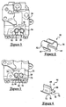
- FIGS. 1-4 show a low and high speed needle valve assembly 20 having a biasing retainer 22, embodying the present invention.
- Mounting threadably to a carburetor body 24 are low and high-speed needle valves 26, 28 which move longitudinally, via rotation, in and out of respective threaded ports 30 defined by the carburetor body 24.
- Air flowing through a throttling bore 31 extending through the carburetor body 24 mixes with a prescribed fuel quantity, or flow rate, controlled by the low and high speed needle valves 26, 28.
- the fuel flow rate within the carburetor body 24 is adjusted by threadably rotating the needle 32 within the respective port 30 either inward to reduce the fuel flow or outward from the carburetor body 24 to increase the fuel flow.
- the low and high-speed needle valves 26, 28 each have a spring 34 and a shank or needle 32.
- the spring 34 provides resistance against unintentional rotation of the needle 32.
- the spring 34 concentrically encircles the needle 32 and is compressed axially between a radially extended head 36 of the needle 32 and the carburetor body 24, the spring 34 engaging an inward facing annular surface 38 defined by the radially expanded head 36.
- the axial constant force produced by the compression of the spring 34 provides the resistance which restrains rotation of the needle 32 by creating friction between the threads of the carburetor body 24 and the needle 32 within the port 30.
- the low and high-speed needle valves 26, 28 of each carburetor are adjusted and set at the factory by the engine manufacturer after the carburetor body 24 is mounted to a running combustion engine, not shown. If the fuel and air mixture is too lean, the running engine may over heat causing warranty concerns. If the fuel and air mixture is too rich, government regulatory emission requirements may be exceeded or violated. Therefore, limiting adjustment capability by the end user of the engine of the low and high-speed needle valves 26, 28 within an acceptable range is desirable.
- the engagement of known limiter caps 40 to the valves 26, 28 establishes the end user adjustment range for fuel flow within the carburetor (i.e. neither too rich nor too lean).
- the limiter caps 40 are press fitted over the heads 36 of the low and high-speed needle valves 26, 28 in the factory after the proper fuel flow settings are made.
- the press fitting of the limiter caps 40 to the heads 36 of either one or both of the needles 32 may unintentionally rotate, wobble or laterally shift the needles causing the factory setting and prescribed adjustment range of the needles 32 to be altered or changed.
- the single retainer 22 of the present invention engages and laterally biases a shank 46 of each needle 32 which protrudes outward from the carburetor body 24.
- the retainer 22 is axially aligned and disposed radially outward from the respective springs 34.
- the lateral force exerted by the retainer 22 against the springs 34 causes the springs 34 to exert a lateral force against the shanks 46 of the needles 32.
- the needles 32 therefore, are skewed against, or tend to favor one side, of the respective ports 30.
- the resultant friction between the springs 34 and the shanks 46 along with the increased friction between the threads of the needles 32 and ports 30 will assist the springs 34 to further resist any rotation of the needles 32. That is, the axial force produced by the springs 34 is compounded by the lateral force produced by the retainer 22.
- the necessity of utilizing the spring 34 to resist rotation can be eliminated with a sufficiently strong or appropriately sized retainer 22. In such an embodiment, the force produced by the retainer 22 is exerted directly on the shanks 46 of the low and high speed needle valves 26, 28.
- Another feature of the retainer 22 is the elimination or reduction of needle tip 48 wobble within an orifice of the fuel flow channel of the carburetor body 24, not shown.
- the wobble action of the tip 48 of the needle 32 is caused by machining tolerance limitations of the carburetor body 24 threads contained within port 30 and the mating threads of needle 32.
- the resultant wobble can affect fuel flow causing a rough running combustion engine.
- the exertion of a lateral bias or force upon the shanks 46 of the needles 32 by the retainer 22 will produce a longitudinal stress and strain along the needle 32. This causes the needle 32 to favor or even bear on one side of the orifice and thereby eliminates some or all of the adverse wobble effects.
- a first embodiment of the retainer 22 is illustrated as a clip retainer 50 which laterally engages both springs 34 of the respective low and high-speed needle valves 26, 28 to laterally bias the projecting portions of the shanks 46 toward one another.
- An angled first leg 52 of the clip retainer 50 engages the spring 34 and thereby interconnects with a longitudinal outward surface 56 of the shank 46 of the low speed needle valve 26, which faces outward with respect to the high-speed needle valve 28.
- An angled second leg 54 of the clip retainer 50 engages the other spring 34 and interconnects with a longitudinal outward face 56 of the shank 46 of the high-speed needle valve 28, which faces outward with respect to the shank 46 of the low-speed needle valve 26.
- the clip retainer 50 laterally snap fits or is interference fitted about both the low and high-speed needle valves 26, 28.
- the distal ends 60, 62 of the respective first and second legs 52, 54 bend substantially radially outward with respect to the shank 46 of the respective low and high-speed needle valves 26, 28.
- a second embodiment of the retainer 22 is shown as a wedge retainer 64.
- the wedge retainer 64 may take the form of a variety of shapes including an L-shape, an I-shape and preferably a T-shape.
- the wedge retainer 64 has a substantially planar primary member 66 which is wedged, via a snap fit, between and thereby engages the springs 34 of the low and high-speed needle valves 26, 28. The wedging effect causes the projecting portions of the shanks 46 to laterally bias outward from one another.
- Providing the snap fit is an enlarged distal end 68 of the primary member 66.
- the thickness of the distal end 68 is appreciably larger than the distance between the low and high speed needle valves 26, 28 in the assembled state.
- the primary member 66 also has an enlarged base end 70 ensuring, when coupled with the enlarged distal end 68, that the wedge retainer 64 has minimal lateral movement and remains wedged between the springs 34 or shanks 46 during end user adjustment rotation of the low or high-speed needle valves 26, 28.
- the primary member 66 with the enlarged distal and base ends 68, 70 form the I-shape referred to above.
- the primary member 66 of the wedge retainer 64 engages the springs 34 on one side between the distal and base ends 68, 70 and thereby interconnects with a longitudinal inward face 71 of the shank 46 of the low-speed needle valve 26 which radially faces generally toward the shank 46 of the high-speed needle valve 28.
- the primary member 66 engages the other spring 34 on the other side and thereby interconnects with the longitudinal inward surface 71 of the shank 46 of the high speed needle valve 28 which faces substantially toward the shank 46 of the low-speed needle valve 26.
- the wedge retainer 64 has a substantially planar first base member 72 extending substantially perpendicularly from the primary member 66 along the base end 70.
- Base member 72 is disposed generally tangentially with respect to the shank 46 of the low-speed needle valve 26.
- the primary member 66 coupled with the first base member 72 form the L-shape referred to above.
- the wedge retainer 64 also has a substantially planar second base member 74 extending from the primary member 66 along the base end 70, but in an opposite direction with respect to the first base member 72.
- the second base member 74 lies generally tangentially to the shank 46 of the high-speed needle valve 28.
- the first and second base members 72, 74 lie substantially within the same imaginary plane and thereby compose an enlarged surface 76 upon which a force can be exerted to snap fit the wedge retainer 64 between the low-and high-speed needle valves 26, 28.
- the primary, first base and second base members 64, 72, 74 form the T-shape referred to above.
- the retainer 22 is a band retainer 78.
- the band retainer 78 laterally bands or biases together the projecting portions of the shanks 46 of the respective low and high-speed needle valves 26, 28.
- the band retainer 78 encircles both the shanks 46 of the low and high-speed needle valves 26, 28 and may be made of an elastic or plastic material which may also have a shrinking capability upon the application of heat.
- a fourth embodiment of the retainer 22 is shown as being a triangular band retainer 79 having a slightly larger diameter or circumference than the band retainer 78.
- the larger diameter enables the band retainer 79 to encircle not only the shanks 46 but also a pin 80 which rigidly protrudes outward from the carburetor body 24.
- the pin 80 is preferably and substantially disposed at an equal distance from the low and high-speed needle valves 26, 28.
- the triangular band retainer 79 can be made of the same material as the band retainer 78.
- a fifth embodiment of the retainer 22 is shown as being a ring retainer 82 preferably made of a plastic material.
- the ring retainer 82 biases the projecting portions of the shanks 46 of the low and high-speed needle valves 26, 28 similar to the wedge retainer 64.
- the ring retainer 82 is concentrically disposed about the spring 34 and the shank 46 of either the low or high-speed needle valves 26, 28.
- the thickness of the ring retainer 82 wall is slightly larger than the distance between the needle valves 26, 28 and is defined by a circumferential inward surface 84 and a circumferential outward surface 86. Because the radial distance between the inward surface 84 and the outward surface 86 is larger than the distance between the springs 34, the ring retainer 82 laterally biases the projecting portions of the shanks 46 outward or away from one another.
- a sixth embodiment of the retainer 22 is shown as being a block retainer 88.
- the block retainer 88 laterally displaces either one of the shanks 46 of the low and high-speed needle valves 26, 28.
- the block retainer 88 has a continuous curved surface 90 defining an angled bore 91 and extended between an inward perimeter 92 and an outward perimeter 94.
- the inward perimeter 92 is centered about a centerline 96 of the respective hole 30.
- the outward perimeter 94 is radially mis-aligned to the centerline 96 of the hole 30. This mis-alignment forces the low or high-speed needle valves 26, 28 to become laterally displaced.
- the non-displaced needle valve inserts within a pilot hole 98 (shown in FIG. 15) of the block retainer 88 which is centered about the centerline 96 of the other hole 30.
- block retainer 88' is shown wherein lateral displacement of both the low and high-speed needle valves 26, 28 is achieved by replacement of the pilot hole 98 with another angled bore 91.
- the bores 91 are preferably angled toward or away from one another and are preferably not parallel to one another. The opposing angles will help avoid misalignment of the block retainer 88 to the carburetor body 24 during assembly.
- an indexing feature 100 of the block retainer 88 mates with a mating indexing feature 102 (shown in FIG. 16) on the carburetor body 24.
- the indexing feature 100 is an inward extended pin and the mating indexing feature 102 of the carburetor body 24 is an orifice or receptacle.
- a threaded fastener 104 secures the block retainer 88 to the carburetor body 24.
- the threaded fastener is a screw or bolt, counter sunk into the block retainer 88 and threaded into the carburetor body 24.
- FIG. 16 yet another embodiment of the retainer assembly 20' is shown wherein either the low or high-speed needle valve 26, 28 is a fuel needle valve 106 and the remaining valve is eliminated and replaced with a dummy needle valve or shaft 108 which projects rigidly outward from the carburetor body 24'.
- the retainer 22 engages the fuel-air mixture needle valve 106 and the shaft 108 as it does with the low and high-speed needle valves 26, 28 shown in FIG. 1.
- the shaft 108 is press fitted into the pilot hole 98. This press fit eliminates the need for the threaded fastener 104.
- the preferable material for the block retainer 88 is plastic.
Landscapes
- Engineering & Computer Science (AREA)
- Chemical & Material Sciences (AREA)
- Combustion & Propulsion (AREA)
- Mechanical Engineering (AREA)
- General Engineering & Computer Science (AREA)
- Control Of The Air-Fuel Ratio Of Carburetors (AREA)
Abstract
Description
Claims (29)
- A retaining device to maintain yieldingly the rotational setting of a fuel needle valve of a carburetor comprising:a rotatable elongated needle of the fuel needle valve engaged threadably to the carburetor, the needle having a shank extended outward from the carburetor;a shaft extended outward from the carburetor, the shaft being parallel to the shank of the fuel needle valve; anda retainer engaged to and laterally biasing the fuel needle valve and the shaft.
- The retaining device according to claim 1 further comprising:the projecting needle valve shank biased laterally toward the shaft by the retainer;the shank and the shaft each having a longitudinal outward surface, the outward surface of the shank facing away from the shaft, the outward surface of the shaft facing away from the shank; andthe retainer being a clip retainer having a first leg engaged to the outward surface of the shank, a second leg engaged to the outward surface of the shaft, the first leg engaged to the second leg, the clip retainer being snap fitted from a lateral direction about the shank and the shaft.
- The retaining device according to claim 2 wherein the first and second legs of the clip retainer each have a distal end curving radially outward from the respective shank and shaft.
- The retaining device according to claim 3 wherein the fuel needle valve is a low-speed needle valve and the shaft is the rotatable shank of a high-speed needle valve.
- The retaining device according to claim 1 further comprising:the projecting shank biased laterally toward the shaft by the retainer;the shank and the shaft each having a longitudinal outward surface, the outward surface of the shank facing away from the shaft, the outward surface of the shaft facing away from the shank; andthe retainer being a band retainer encircling both the shank and the shaft, the band retainer resiliently engaging the outward surfaces of the shank and shaft.
- The retaining device according to claim 5 further comprising a pin extended outward from the carburetor body and disposed parallel to the shank and shaft, the band retainer being a triangular band retainer also encircling the pin.
- The retaining device according to claim 6 wherein the band retainer is made of a resiliently stretchable material and thereby stretched prior to being installed from an axially inward direction about the shank and shaft.
- The retaining device according to claim 6 wherein the band retainer is made of a plastic material and shrunk by the application of heat after the band retainer is installed from an axially inward direction about the shank and shaft.
- The retaining device according to claim 8 wherein the fuel needle valve is a low speed needle valve and the shaft is the rotatable shank of a high-speed needle valve.
- The retaining device according to claim 1 further comprising:the shank being biased laterally away from the shaft by the retainer;a longitudinal inward surface of the shank of the fuel needle valve facing a longitudinal inward surface of the shaft; andthe retainer being a wedge retainer having a primary member extended from an enlarged distal end to an enlarged base end, the primary member disposed between and engaged to the inward surfaces of the shank and shaft thereby biasing the shank laterally away from the shaft.
- The retaining device according to claim 10 wherein the wedge retainer has a first base member engaged to the base end and disposed perpendicularly to the primary member.
- The retaining device according to claim 11 wherein the wedge retainer has a second base member engaged to the base end opposite the first base member, the first and second base members lying within the same imaginary plane.
- The retaining device according to claim 12 wherein the fuel needle valve is a low speed needle valve and the shaft is the rotatable shank of a high-speed needle valve.
- The retaining device according to claim 1 further comprising:the retainer being a block retainer laterally displacing the projecting shank of the fuel needle valve, the block retainer engaged laterally to the shank and the shaft;the block retainer having a pilot hole and a continuous curved surface defining an angled bore, the curved surface extending between an inward perimeter and an outward perimeter, the shank disposed in the angled bore and the shaft disposed in the pilot hole; andthe hole of the carburetor body having a centerline, the inward perimeter centered about the centerline, the outward perimeter mis-aligned radially to the centerline.
- The retaining device according to claim 14 wherein the block retainer is secured to the carburetor body by a threaded fastener.
- The retaining device according to claim 15 wherein the fuel needle valve is a low speed needle valve and the shaft is the rotatable shank of a high speed needle valve, and wherein the pilot hole of the block retainer is a second angled bore.
- The retaining device according to claim 16 wherein the block retainer has an indexing feature and the carburetor body has a mating indexing feature for aligning the retainer block to the carburetor body.
- The retaining device according to claim 1 wherein the fuel needle valve is a low speed needle valve having a head engaged with the shank, a spring disposed about the shank and axially compressibly between the carburetor body and the head, the head having an annular surface facing the carburetor body, the shank defined radially by a longitudinal outward surface and a longitudinal inward surface, the annular surface disposed radially outward from and perpendicular to the outward and inward surfaces; a high speed needle valve having a rotatable elongated shank and a head engaged with the shank, the elongated shank engaged threadably to and projecting outward from the carburetor body, a spring disposed about the shank and axially compressibly between the carburetor body and the head, the head having an annular surface facing the carburetor body, the shank defined radially by a longitudinal outward surface and a longitudinal inward surface, the annular surface disposed radially outward from and perpendicular to the outward and inward surfaces, the shank of the high speed needle valve being parallel to the shank of the low-speed needle valve, the inward surface of the low-speed needle valve shank facing the inward surface of the high-speed needle valve shank; and the retainer engaged resiliently to the springs of the low and high-speed needle valves, the springs thereby biasing laterally the low-speed needle valve shank and the high-speed needle valve shank.
- The retaining device according to claim 18 further comprising two limiter caps engaged to the respective heads of the low and high-speed needle valves, wherein the limiter caps are engaged to the heads after the retainer is engaged to the springs of the low and high-speed needle valves.
- The retaining device according to claim 18 wherein the retainer is a clip retainer having a first leg engaged laterally to the spring engaged laterally to the adjacent outward surface of the low-speed needle valve shank, a second leg engaged laterally to the spring engaged laterally to the outward surface of the high-speed needle valve shank, the first leg engaged unitarily to the second leg, the clip retainer interference fitted laterally about the respective springs of the low and high-speed needle valve shanks, wherein the low-speed needle valve projecting shank is biased laterally toward the high-speed needle valve projecting shank by the retainer.
- The rotational retaining device according to claim 20 wherein the first and second legs of the clip retainer each have a distal end curving radially outward from the respective low and high-speed needle valve shanks.
- The retaining device according to claim 18 wherein the retainer is a band retainer encircling both the springs of the low and high-speed needle valve shanks, the band retainer resiliently laterally engaging the springs which laterally engage the outward surfaces of the low and high-speed needle valve shanks, wherein the low-speed needle valve projecting shank is biased laterally toward the high-speed needle valve projecting shank by the band retainer.
- The retaining device according to claim 22 wherein the band retainer is stretched prior to installing axially about the springs of the low and high-speed needle valve shanks.
- The retaining device according to claim 22 wherein the band retainer is made of a polymeric material and shrunk by the application of heat after the band retainer is placed about the springs of the low and high-speed needle valve shanks.
- The retaining device according to claim 18 wherein the retainer is a wedge retainer having a primary member having an enlarged distal end and an enlarged base end, the primary member extended between the distal and base ends, the primary member engaged laterally to the springs and the springs engaged laterally to the inward surfaces of the low and high-speed needle valve shanks between the distal and base ends, wherein the expanded distal end is snap fitted laterally past the inward surfaces of the low and high-speed needle valve shanks, and the low-speed needle valve projecting shank is biased laterally away from the high speed needle valve projecting shank by the wedge retainer.
- The retaining device according to claim 25 wherein the wedge retainer has a first member engaged to the base end and extended perpendicularly from the primary member, the first member disposed tangentially to the spring of the low-speed needle valve.
- The retaining device according to claim 26 wherein the wedge retainer has a second member engaged to the base end and extended perpendicularly from the primary member, the first member disposed tangentially to the spring of the high-speed needle valve.
- The retaining device according to claim 18 wherein the retainer is a ring retainer having a circumferential inward surface engaged to and encircling the spring of the low-speed needle valve and a circumferential outward surface engaged to the spring of the high-speed needle valve, wherein the low speed needle valve projecting shank is biased laterally away from the high-speed needle valve projecting shank by the ring retainer.
- The retaining device according to claim 18 wherein the retainer is a ring retainer having a circumferential inward surface engaged to and encircling the spring of the high-speed needle valve and a circumferential outward surface engaged to the spring of the low-speed needle valve, wherein the high-speed needle valve projecting shank is biased laterally away from the low-speed needle valve projecting shank by the ring retainer.
Applications Claiming Priority (2)
| Application Number | Priority Date | Filing Date | Title |
|---|---|---|---|
| US798602 | 2001-03-02 | ||
| US09/798,602 US6402125B1 (en) | 2000-03-29 | 2001-03-02 | Carburetor valve rotational setting retainer assembly |
Publications (2)
| Publication Number | Publication Date |
|---|---|
| EP1236882A2 true EP1236882A2 (en) | 2002-09-04 |
| EP1236882A3 EP1236882A3 (en) | 2004-01-21 |
Family
ID=25173818
Family Applications (1)
| Application Number | Title | Priority Date | Filing Date |
|---|---|---|---|
| EP02002888A Withdrawn EP1236882A3 (en) | 2001-03-02 | 2002-02-08 | Carburetor valve rotational setting retainer assembly |
Country Status (3)
| Country | Link |
|---|---|
| US (2) | US6402125B1 (en) |
| EP (1) | EP1236882A3 (en) |
| JP (1) | JP2002276467A (en) |
Families Citing this family (8)
| Publication number | Priority date | Publication date | Assignee | Title |
|---|---|---|---|---|
| DE10001583C2 (en) * | 2000-01-17 | 2002-03-21 | Bosch Gmbh Robert | Method and device for monitoring the function of a gas flow control element, in particular a swirl cap, in an internal combustion engine |
| US6402125B1 (en) * | 2000-03-29 | 2002-06-11 | Walbro Corporation | Carburetor valve rotational setting retainer assembly |
| DE202004012860U1 (en) * | 2004-02-05 | 2005-06-16 | Dolmar Gmbh | Limiter cap for carburetor, has adjustment prevention device and guiding nose, where cap surrounds portion of set screw for positive locking, and transition area between screw head and needle extends in ring shape around needle |
| US7097165B1 (en) | 2005-04-13 | 2006-08-29 | Walbro Engine Management, L.L.C. | Carburetor fuel adjustment and limiter assembly |
| US7240896B1 (en) | 2005-05-05 | 2007-07-10 | Walbro Engine Management, L.L.C. | Carburetor fuel adjustment assembly |
| US8376324B2 (en) * | 2006-01-09 | 2013-02-19 | Jiangsu Jianghuai Engine Co., Ltd. | Readjustment-preventing carburetor and a method for preventing the carburetor from being readjusted |
| US8348244B2 (en) | 2010-07-24 | 2013-01-08 | Walbro Engine Management, L.L.C. | Carburetor valve adjustment limiter |
| US10907842B2 (en) | 2018-09-06 | 2021-02-02 | David Nunes | Humidifier assembly |
Family Cites Families (26)
| Publication number | Priority date | Publication date | Assignee | Title |
|---|---|---|---|---|
| US2618473A (en) * | 1951-02-09 | 1952-11-18 | Whitford Albert Edward | Locking block for guarding carburetor jet screws |
| US3425672A (en) * | 1967-06-01 | 1969-02-04 | Gen Motors Corp | Adjusting screw retaining means |
| US3469825A (en) * | 1967-10-12 | 1969-09-30 | Outboard Marine Corp | Alignment bushing for needle valve |
| JPS6039469Y2 (en) * | 1976-04-23 | 1985-11-26 | 日産自動車株式会社 | carburetor idle adjustment device |
| JPS5569748A (en) * | 1978-11-20 | 1980-05-26 | Walbro Far East | Carburetor |
| US4283353A (en) * | 1979-05-15 | 1981-08-11 | Colt Industries Operating Corp | Tamper proof sealing plug |
| DE3005854A1 (en) * | 1980-02-16 | 1981-09-03 | Fa. Andreas Stihl, 7050 Waiblingen | CARBURETTOR FOR AN INTERNAL COMBUSTION ENGINE |
| US4568499A (en) * | 1984-07-09 | 1986-02-04 | Outboard Marine Corporation | Carburetor with self seating needle valve |
| USH463H (en) * | 1985-03-15 | 1988-05-03 | Ford Motor Company | Carburetor spring retainer clip |
| US4759883A (en) * | 1987-03-12 | 1988-07-26 | Walbro Corporation | Temperature compensated fluid flow metering system |
| US5133905A (en) * | 1989-10-26 | 1992-07-28 | Walbro Corporation | Fuel metering method and apparatus |
| US5236634A (en) * | 1992-09-23 | 1993-08-17 | Walbro Corporation | Carburetor needle valve adjustment limiter cap and method of adjusting fuel flow |
| US5262092A (en) * | 1993-01-26 | 1993-11-16 | Walbro Corporation | Synthetic composite fuel metering membrane |
| JPH06317222A (en) * | 1993-04-30 | 1994-11-15 | Shinagawa Diecast Kogyo Kk | Fuel adjusting device of carburetor |
| JPH0882245A (en) * | 1994-09-13 | 1996-03-26 | Shinagawa Diecast Kogyo Kk | Fuel control device for carburetor |
| US5772927A (en) * | 1994-12-01 | 1998-06-30 | U.S.A. Zama, Inc. | Carburetor fuel adjusting device |
| IES950133A2 (en) * | 1995-02-17 | 1996-05-15 | Barcarole Ltd | An adjustment screw apparatus |
| US5753148A (en) | 1995-08-30 | 1998-05-19 | Walbro Corporation | Carburetor needle valve adjustment limiter cap apparatus and method of adjusting fuel flow |
| US5984281A (en) * | 1995-08-30 | 1999-11-16 | Walbro Corporation | Carburetor needle valve and limiter cap installation and adjustment apparatus |
| JPH09158783A (en) * | 1995-12-12 | 1997-06-17 | Shinagawa Diecast Kogyo Kk | Air-fuel ratio adjusting device of carburetor |
| IES70513B2 (en) | 1996-03-26 | 1996-11-27 | Barcarole Ltd | A carburetor adjustment screw apparatus |
| US5707561A (en) | 1996-07-18 | 1998-01-13 | Walbro Corporation | Tamper resistant carburetor needle valve adjustment limiter |
| US6003845A (en) | 1998-03-24 | 1999-12-21 | Walbro Corporation | Fuel mixture adjusting and limiting device |
| US6402125B1 (en) * | 2000-03-29 | 2002-06-11 | Walbro Corporation | Carburetor valve rotational setting retainer assembly |
| US6402124B1 (en) * | 2000-03-29 | 2002-06-11 | Walbro Corporation | Carburetor fuel mixture adjustment assembly |
| US6302384B1 (en) | 2000-06-01 | 2001-10-16 | Walbro Corporation | Needle valve carburetor |
-
2001
- 2001-03-02 US US09/798,602 patent/US6402125B1/en not_active Expired - Fee Related
-
2002
- 2002-02-01 US US10/060,446 patent/US6540212B2/en not_active Expired - Lifetime
- 2002-02-08 EP EP02002888A patent/EP1236882A3/en not_active Withdrawn
- 2002-02-13 JP JP2002035412A patent/JP2002276467A/en active Pending
Also Published As
| Publication number | Publication date |
|---|---|
| JP2002276467A (en) | 2002-09-25 |
| US6402125B1 (en) | 2002-06-11 |
| EP1236882A3 (en) | 2004-01-21 |
| US20020070466A1 (en) | 2002-06-13 |
| US6540212B2 (en) | 2003-04-01 |
Similar Documents
| Publication | Publication Date | Title |
|---|---|---|
| US5753148A (en) | Carburetor needle valve adjustment limiter cap apparatus and method of adjusting fuel flow | |
| DE69312611T2 (en) | Cap to limit the adjustment of a carburettor adjustment needle | |
| US5707561A (en) | Tamper resistant carburetor needle valve adjustment limiter | |
| US6540212B2 (en) | Carburetor valve rotational setting retainer assembly | |
| US6332256B1 (en) | Holding device | |
| CA2278996C (en) | Carburetor with secured control screw | |
| US5961896A (en) | Carburetor fuel adjusting device | |
| US11293380B2 (en) | Charge forming device with adjustable valve limiter | |
| US7097165B1 (en) | Carburetor fuel adjustment and limiter assembly | |
| US20040007788A1 (en) | Carburetor air-fuel mixture adjustment assembly | |
| US6467757B1 (en) | Carburetor valve adjustment limiter cap assembly | |
| US5630965A (en) | Low force limit device | |
| US20210381470A1 (en) | Tamper resistant adjustment valve for a charge forming device | |
| JP4993861B2 (en) | Limited cap for carburetor | |
| US11761403B2 (en) | Charge forming device with tamper resistant adjustable valve | |
| US6691988B1 (en) | Tamper resistant carburetor mixture needles | |
| US7240896B1 (en) | Carburetor fuel adjustment assembly | |
| DE69311995T2 (en) | Cap to limit the adjustment of a carburettor adjustment needle | |
| US20240026842A1 (en) | Flow control restrictor | |
| US20240026841A1 (en) | Fuel regulator | |
| US20050040547A1 (en) | Carburetor air-fuel mixture adjustment assembly | |
| US7077387B1 (en) | Limited access adjustment system for an internal combustion engine | |
| JPH07286560A (en) | Operation limiting device for fuel adjusting needle valve of carburetor | |
| JPH0236934Y2 (en) | ||
| JP2006105127A (en) | Air fuel mixture adjustment device for carburetor |
Legal Events
| Date | Code | Title | Description |
|---|---|---|---|
| PUAI | Public reference made under article 153(3) epc to a published international application that has entered the european phase |
Free format text: ORIGINAL CODE: 0009012 |
|
| AK | Designated contracting states |
Kind code of ref document: A2 Designated state(s): AT BE CH CY DE DK ES FI FR GB GR IE IT LI LU MC NL PT SE TR |
|
| AX | Request for extension of the european patent |
Free format text: AL;LT;LV;MK;RO;SI |
|
| PUAL | Search report despatched |
Free format text: ORIGINAL CODE: 0009013 |
|
| AK | Designated contracting states |
Kind code of ref document: A3 Designated state(s): AT BE CH CY DE DK ES FI FR GB GR IE IT LI LU MC NL PT SE TR |
|
| AX | Request for extension of the european patent |
Extension state: AL LT LV MK RO SI |
|
| RIC1 | Information provided on ipc code assigned before grant |
Ipc: 7F 02B 63/02 B Ipc: 7F 02M 3/10 B Ipc: 7F 02M 19/04 A |
|
| 17P | Request for examination filed |
Effective date: 20040507 |
|
| AKX | Designation fees paid |
Designated state(s): AT BE CH CY DE DK ES FI FR GB GR IE IT LI LU MC NL PT SE TR |
|
| STAA | Information on the status of an ep patent application or granted ep patent |
Free format text: STATUS: THE APPLICATION HAS BEEN WITHDRAWN |
|
| 18W | Application withdrawn |
Effective date: 20050120 |