EP1236868A1 - Powdered metal assemblies with fastener inserts - Google Patents
Powdered metal assemblies with fastener inserts Download PDFInfo
- Publication number
- EP1236868A1 EP1236868A1 EP02075055A EP02075055A EP1236868A1 EP 1236868 A1 EP1236868 A1 EP 1236868A1 EP 02075055 A EP02075055 A EP 02075055A EP 02075055 A EP02075055 A EP 02075055A EP 1236868 A1 EP1236868 A1 EP 1236868A1
- Authority
- EP
- European Patent Office
- Prior art keywords
- fastener
- component assembly
- flange
- assembly
- opening
- Prior art date
- Legal status (The legal status is an assumption and is not a legal conclusion. Google has not performed a legal analysis and makes no representation as to the accuracy of the status listed.)
- Granted
Links
- 239000012255 powdered metal Substances 0.000 title claims abstract description 21
- 230000000712 assembly Effects 0.000 title abstract description 8
- 238000000429 assembly Methods 0.000 title abstract description 8
- 238000004519 manufacturing process Methods 0.000 abstract 1
- 238000003754 machining Methods 0.000 description 4
- 230000013011 mating Effects 0.000 description 2
- 238000000034 method Methods 0.000 description 2
- 238000005056 compaction Methods 0.000 description 1
- 230000009977 dual effect Effects 0.000 description 1
- 230000010354 integration Effects 0.000 description 1
- 239000000463 material Substances 0.000 description 1
- 230000004048 modification Effects 0.000 description 1
- 238000012986 modification Methods 0.000 description 1
- 238000000926 separation method Methods 0.000 description 1
- 238000005245 sintering Methods 0.000 description 1
Images


Classifications
-
- F—MECHANICAL ENGINEERING; LIGHTING; HEATING; WEAPONS; BLASTING
- F01—MACHINES OR ENGINES IN GENERAL; ENGINE PLANTS IN GENERAL; STEAM ENGINES
- F01L—CYCLICALLY OPERATING VALVES FOR MACHINES OR ENGINES
- F01L13/00—Modifications of valve-gear to facilitate reversing, braking, starting, changing compression ratio, or other specific operations
-
- F—MECHANICAL ENGINEERING; LIGHTING; HEATING; WEAPONS; BLASTING
- F01—MACHINES OR ENGINES IN GENERAL; ENGINE PLANTS IN GENERAL; STEAM ENGINES
- F01L—CYCLICALLY OPERATING VALVES FOR MACHINES OR ENGINES
- F01L1/00—Valve-gear or valve arrangements, e.g. lift-valve gear
- F01L1/46—Component parts, details, or accessories, not provided for in preceding subgroups
-
- F—MECHANICAL ENGINEERING; LIGHTING; HEATING; WEAPONS; BLASTING
- F16—ENGINEERING ELEMENTS AND UNITS; GENERAL MEASURES FOR PRODUCING AND MAINTAINING EFFECTIVE FUNCTIONING OF MACHINES OR INSTALLATIONS; THERMAL INSULATION IN GENERAL
- F16B—DEVICES FOR FASTENING OR SECURING CONSTRUCTIONAL ELEMENTS OR MACHINE PARTS TOGETHER, e.g. NAILS, BOLTS, CIRCLIPS, CLAMPS, CLIPS OR WEDGES; JOINTS OR JOINTING
- F16B2200/00—Constructional details of connections not covered for in other groups of this subclass
- F16B2200/30—Dovetail-like connections
-
- F—MECHANICAL ENGINEERING; LIGHTING; HEATING; WEAPONS; BLASTING
- F16—ENGINEERING ELEMENTS AND UNITS; GENERAL MEASURES FOR PRODUCING AND MAINTAINING EFFECTIVE FUNCTIONING OF MACHINES OR INSTALLATIONS; THERMAL INSULATION IN GENERAL
- F16B—DEVICES FOR FASTENING OR SECURING CONSTRUCTIONAL ELEMENTS OR MACHINE PARTS TOGETHER, e.g. NAILS, BOLTS, CIRCLIPS, CLAMPS, CLIPS OR WEDGES; JOINTS OR JOINTING
- F16B2200/00—Constructional details of connections not covered for in other groups of this subclass
- F16B2200/50—Flanged connections
- F16B2200/509—Flanged connections clamped
-
- Y—GENERAL TAGGING OF NEW TECHNOLOGICAL DEVELOPMENTS; GENERAL TAGGING OF CROSS-SECTIONAL TECHNOLOGIES SPANNING OVER SEVERAL SECTIONS OF THE IPC; TECHNICAL SUBJECTS COVERED BY FORMER USPC CROSS-REFERENCE ART COLLECTIONS [XRACs] AND DIGESTS
- Y10—TECHNICAL SUBJECTS COVERED BY FORMER USPC
- Y10T—TECHNICAL SUBJECTS COVERED BY FORMER US CLASSIFICATION
- Y10T403/00—Joints and connections
- Y10T403/70—Interfitted members
- Y10T403/7062—Clamped members
Definitions
- This invention relates to component assemblies including simplified hardened powdered metal components.
- powdered metal (PM) components may be made with high dimensional accuracy which provides hardened components that require little or no further finishing.
- the component design must be producible by opposing dies with punches aligned in the direction of die motion.
- a hardened cam or lever for example, may be formed with a negative cam curvature that is difficult to produce without special grinding equipment or with non round openings or slots that would require special machining processes.
- the present invention provides a solution in modification of the PM component to provide slotted recesses that extend from a side in the direction of die punch motion through fastener receiving seats that are engaged by flanges of a second component.
- the recesses receive inserts installed from the side and having threaded openings that align with openings in the mating flanges to receive fasteners for holding the components of the assemblies together.
- the assembly designs allow the wearing components to be made of powdered metal, which is hardened at the time of sintering, with wearing surfaces ready for use with little or no further machining.
- the inserts may be made by any suitable processes and machined and hardened as necessary. Where dual inserts are used, they may be provided with heads and inserted from opposite sides of the assemblies to prevent relative lateral shifting of the components after assembly.
- Cam assembly 10 generally indicates an oscillating output cam assembly formed according to the invention for use in an engine variable valve timing mechanism.
- Cam assembly 10 includes a cam component 12, a retainer component 14, a pair of fastener inserts 16 and a pair of fastener screws 18.
- the cam component 12 shown in FIG. 2 is formed by compaction of powdered metal (PM) and sintered to provide a hardened and finished component ready for integration in the assembly 10. While the PM process provides an accurate and acceptable cam surface for many applications, it is possible to further machine the cam and other surfaces by grinding if desired.
- PM powdered metal
- component 12 includes an arched body 20 having a variably curved cam surface 22 along an outer side with a lever boss 24 adjacent one end.
- a D-shaped opening 26 through the boss provides for connection to an associated linkage, not shown.
- a semi-cylindrical inner bearing surface 28 connects at opposite ends with coplanar seats 30.
- Each of the seats is divided by a slot 32, extending parallel to the bearing surface 28.
- An enlarged through opening or recess 34 connected with the slot 32 extends through the body spaced slightly from the respective seat 30 to form inwardly projecting lips 36.
- Each recess 34 may be of any suitable shape, but semicircular openings with a flat side toward the slot are preferred at present as resulting in lower stresses.
- the fastener inserts 16 in FIG. 3 are shaped to fit into the recesses 34, thus having as shown D-shaped bodies 38, each with a small shoulder 40 preferably provided at one end.
- a threaded fastener engaging opening 42 extends into the body from the flat side of each body 38.
- the inserts 16 are insertable into the recesses 34 with their openings 42 facing the slots 32 on the seat sides of the recesses.
- the shoulders 40 may be received in mating grooves 44 at the edges of the body recesses 34.
- the heads of the two inserts 16 are disposed at opposite sides of the bodies 20 for reasons to be subsequently made clear.
- the retainer component 14 of the cam assembly 10 of FIG. 1 may be a cast and machined or otherwise formed member formed with an arch shape defining internally a semi-circular bearing surface 46. At the ends of the arch, are formed outwardly protruding flanges 48 with coplanar seat engaging surfaces 50 seated in assembly against the seats 30 of the cam body 20. Each flange has a fastener receiving opening 52 aligned with the slots 32 and the openings 42 in the inserts 16. The fastener screws 18 are received in these openings 52, 42 and cooperate with the inserts 16 to hold the cam component 12 and the retainer component together in the assembly 10.
- the bearing surfaces 28, 46 join to provide a circular bearing opening for supporting the oscillating cam assembly 10 on a rotating shaft in a mechanism, not shown.
- the fastener screws 18 engage the threaded openings 42 and the inserts 16 engage the lips 36 to fix the retainer and cam components together.
- the shoulders 40 of the inserts, acting against opposite sides of the cam body 12, provide additional assurance against separation of the assembly members by preventing the inserts from sliding in either direction in their recesses 34.
- a control lever assembly 60 is shown which is an alternative embodiment of component assembly made in accordance with the invention.
- Assembly 60 includes a lever portion 62, retainer portion 64, inserts 66 and fastener screws 68.
- the retainer portion 64 and screws 68 are essentially identical to components 14, 18 previously described so that further description is unnecessary.
- the lever portion 62 is formed from hardened powdered metal (PM) as is the cam component 12 of the assembly 10.
- Lever portion 62 includes an arched body 70 with a semi-cylindrical bearing surface 72, which adjoins the bearing surface of the retainer portion 64 to form an annular bearing as before.
- Lever portion 62 further includes a boss 74 with pin opening 76 and a driving fork 78 forming a slot 80 for receiving a pin of an associated control lever, not shown.
- the PM material provides good wear qualities for the slot 80, pin opening 76 and the bearing surface 72.
- Portion 62 also includes seats 82 for engaging flanges of the retainer portion 64. Slots 84 and through recesses 86 are also provided in the seats 82 to receive the inserts 66. However, the recesses 86 and inserts 66 have square cross sections instead of D-shaped ones as alternatives to the embodiment of FIG. 1.
- control lever assembly 60 As the novel features of control lever assembly 60 are similar to those of cam assembly 10 and the advantages are essentially the same, further explanation appears unnecessary.
Landscapes
- Engineering & Computer Science (AREA)
- Mechanical Engineering (AREA)
- General Engineering & Computer Science (AREA)
- Valve Device For Special Equipments (AREA)
Abstract
Description
- This invention relates to component assemblies including simplified hardened powdered metal components.
- It is known in the art that powdered metal (PM) components may be made with high dimensional accuracy which provides hardened components that require little or no further finishing. However, to reach this result without excessive cost, the component design must be producible by opposing dies with punches aligned in the direction of die motion. Thus, a hardened cam or lever, for example, may be formed with a negative cam curvature that is difficult to produce without special grinding equipment or with non round openings or slots that would require special machining processes.
- In design of a component assemblies such as an oscillating cam and lever or a pivoting timing lever for a variable valve timing mechanism, the ability to use hardened PM parts was desired to avoid the cost of multiple machining processes in forming the components and to provide for variations in cam shape not easily produced by grinding. However, these assemblies included components held together by threaded fasteners received in openings extending normal to the direction of required PM punch motion so that the fastener openings would have to machined in after the forming of the components. This would require making the PM components with lower hardness which would allow subsequent machining and would require subsequent hardening which could result in dimensional distortion. A workable solution was desired.
- The present invention provides a solution in modification of the PM component to provide slotted recesses that extend from a side in the direction of die punch motion through fastener receiving seats that are engaged by flanges of a second component. The recesses receive inserts installed from the side and having threaded openings that align with openings in the mating flanges to receive fasteners for holding the components of the assemblies together.
- The assembly designs allow the wearing components to be made of powdered metal, which is hardened at the time of sintering, with wearing surfaces ready for use with little or no further machining. The inserts may be made by any suitable processes and machined and hardened as necessary. Where dual inserts are used, they may be provided with heads and inserted from opposite sides of the assemblies to prevent relative lateral shifting of the components after assembly.
- These and other features and advantages of the invention will be more fully understood from the following description of certain specific embodiments of the invention taken together with the accompanying drawings.
- In the drawings:
- FIG. 1 is a pictorial view of an oscillating output cam assembly according to the invention
- FIG. 2 is a pictorial view of the powdered metal (PM) cam portion of the assembly of FIG. 1;
- FIG. 3 is a pictorial view of one of the fastener inserts;
- FIG. 4 is an enlarged cross-sectional view through the interface of the fastener and insert holding together the cam and retainer components of the assembly; and
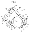
- FIG. 5 is a pictorial view of an alternative application of the invention in a control lever assembly.
-
- Referring now to the drawings in detail,
numeral 10 generally indicates an oscillating output cam assembly formed according to the invention for use in an engine variable valve timing mechanism.Cam assembly 10 includes acam component 12, aretainer component 14, a pair offastener inserts 16 and a pair offastener screws 18. - The
cam component 12, shown in FIG. 2, is formed by compaction of powdered metal (PM) and sintered to provide a hardened and finished component ready for integration in theassembly 10. While the PM process provides an accurate and acceptable cam surface for many applications, it is possible to further machine the cam and other surfaces by grinding if desired. - As shown,
component 12 includes anarched body 20 having a variablycurved cam surface 22 along an outer side with alever boss 24 adjacent one end. A D-shaped opening 26 through the boss provides for connection to an associated linkage, not shown. Internally, a semi-cylindrical inner bearingsurface 28 connects at opposite ends withcoplanar seats 30. Each of the seats is divided by aslot 32, extending parallel to thebearing surface 28. An enlarged through opening orrecess 34 connected with theslot 32 extends through the body spaced slightly from therespective seat 30 to form inwardly projectinglips 36. Eachrecess 34 may be of any suitable shape, but semicircular openings with a flat side toward the slot are preferred at present as resulting in lower stresses. - The fastener inserts 16 in FIG. 3 are shaped to fit into the
recesses 34, thus having as shown D-shaped bodies 38, each with asmall shoulder 40 preferably provided at one end. A threadedfastener engaging opening 42 extends into the body from the flat side of eachbody 38. Theinserts 16 are insertable into therecesses 34 with theiropenings 42 facing theslots 32 on the seat sides of the recesses. Theshoulders 40 may be received inmating grooves 44 at the edges of the body recesses 34. Preferably, the heads of the twoinserts 16 are disposed at opposite sides of thebodies 20 for reasons to be subsequently made clear. - The
retainer component 14 of thecam assembly 10 of FIG. 1 may be a cast and machined or otherwise formed member formed with an arch shape defining internally a semi-circular bearingsurface 46. At the ends of the arch, are formed outwardly protrudingflanges 48 with coplanarseat engaging surfaces 50 seated in assembly against theseats 30 of thecam body 20. Each flange has a fastener receiving opening 52 aligned with theslots 32 and theopenings 42 in theinserts 16. Thefastener screws 18 are received in theseopenings inserts 16 to hold thecam component 12 and the retainer component together in theassembly 10. - In
assembly 10, as shown in FIGS. 1 and 4, thebearing surfaces cam assembly 10 on a rotating shaft in a mechanism, not shown. Thefastener screws 18 engage the threadedopenings 42 and theinserts 16 engage thelips 36 to fix the retainer and cam components together. Theshoulders 40 of the inserts, acting against opposite sides of thecam body 12, provide additional assurance against separation of the assembly members by preventing the inserts from sliding in either direction in theirrecesses 34. - Referring now to FIG. 5, a
control lever assembly 60 is shown which is an alternative embodiment of component assembly made in accordance with the invention.Assembly 60 includes alever portion 62,retainer portion 64,inserts 66 andfastener screws 68. Theretainer portion 64 andscrews 68 are essentially identical tocomponents lever portion 62 is formed from hardened powdered metal (PM) as is thecam component 12 of theassembly 10.Lever portion 62 includes anarched body 70 with asemi-cylindrical bearing surface 72, which adjoins the bearing surface of theretainer portion 64 to form an annular bearing as before. -
Lever portion 62 further includes aboss 74 with pin opening 76 and adriving fork 78 forming aslot 80 for receiving a pin of an associated control lever, not shown. The PM material provides good wear qualities for theslot 80, pin opening 76 and thebearing surface 72.Portion 62 also includesseats 82 for engaging flanges of theretainer portion 64.Slots 84 and throughrecesses 86 are also provided in theseats 82 to receive theinserts 66. However, therecesses 86 andinserts 66 have square cross sections instead of D-shaped ones as alternatives to the embodiment of FIG. 1. - As the novel features of
control lever assembly 60 are similar to those ofcam assembly 10 and the advantages are essentially the same, further explanation appears unnecessary. - While the invention has been described by reference to a preferred embodiment, it should be understood that numerous changes could be made within the spirit and scope of the invention described. Accordingly, it is intended that the invention not be limited to the disclosed embodiments, but that it have the full scope permitted only by the language of the following claims.
Claims (10)
- A component assembly (10) for use in a mechanism, the assembly comprising:a first member (14) including a flange (48) with a fastener receiving opening (52) through the flange;a second member (12) made as a sintered and hardened powdered metal part including a seat (30) engaging the flange (48), a slot (32) in the seat and connecting with an enlarged recess (34) spaced from the seat, the slot (32) and recess (34) opening through a side of the second member adjacent to the seat (30);an insert (16) extending into the recess (34) through the opening, the insert having a fastener engaging opening (42) in one side and aligned with the fastener receiving opening (52) in the flange (48) of the first member (14); anda fastener (68) extending through the flange (48) and the slot (32) and engaging the insert opening (42), thereby fixing the flange (48) of the first member (14) to the seat (30) of the second member (12).
- A component assembly as in claim 1 wherein the recess and the slot extend through the second member
- A component assembly as in claim 1 wherein the second member includes at least one hardened surface for wearing engagement with a cooperating component.
- A component assembly as in claim 1 including at least one lip beside the slot and holding the insert within the recess
- A component assembly as in claim 2 wherein the insert includes a head at one end and engaging the second member at one end of the recess.
- A component assembly as in claim 1 wherein the fastener is threaded and the fastener engaging opening in the insert is a threaded opening
- A component assembly as in claim 1 wherein the assembly includes an annular mounting portion for mounting the assembly for relative rotational motion on a shaft.
- A component assembly as in claim 7 wherein the first and second members each comprise semi-circular parts of the annular mounting portion, the first member having a second flange and the second member having a second seat, slot and recess receiving a second insert with a second fastener securing the second flange to the second seat, the flanges being at opposite ends of the semi-circular first member and the seats, slots, recesses and inserts being at opposite ends of the semi-circular second member and joined to the flanges by the fasteners.
- A component assembly as in claim 8 wherein the second member defines a cam surface of an oscillating cam.
- A component assembly as in claim 8 wherein the second member defines a wearing surface of an actuating lever.
Applications Claiming Priority (2)
| Application Number | Priority Date | Filing Date | Title |
|---|---|---|---|
| US783714 | 1985-10-03 | ||
| US09/783,714 US6520710B2 (en) | 2001-02-14 | 2001-02-14 | Powdered metal assemblies with fastener inserts |
Publications (2)
| Publication Number | Publication Date |
|---|---|
| EP1236868A1 true EP1236868A1 (en) | 2002-09-04 |
| EP1236868B1 EP1236868B1 (en) | 2003-12-03 |
Family
ID=25130174
Family Applications (1)
| Application Number | Title | Priority Date | Filing Date |
|---|---|---|---|
| EP02075055A Expired - Lifetime EP1236868B1 (en) | 2001-02-14 | 2002-01-21 | Powdered metal assemblies with fastener inserts |
Country Status (3)
| Country | Link |
|---|---|
| US (1) | US6520710B2 (en) |
| EP (1) | EP1236868B1 (en) |
| DE (1) | DE60200106T2 (en) |
Families Citing this family (28)
| Publication number | Priority date | Publication date | Assignee | Title |
|---|---|---|---|---|
| US6669219B2 (en) * | 2002-04-10 | 2003-12-30 | Maverick American Llc | Telescoping suspension fork having a quick release wheel axle clamp |
| US7472918B2 (en) * | 2002-04-10 | 2009-01-06 | Blackglass Llc | Telescoping suspension fork having a quick release wheel component clamp |
| US7380754B2 (en) * | 2004-09-30 | 2008-06-03 | The Boeing Company | Clamp block assemblies and methods |
| US9908223B2 (en) | 2016-03-16 | 2018-03-06 | Temper Axle Products Corporation | Systems and methods for preloading a bearing and aligning a lock nut |
| US9764453B1 (en) | 2016-03-16 | 2017-09-19 | Temper Axle Products Corporation | Systems and methods for preloading a bearing |
| US9599164B1 (en) | 2006-01-27 | 2017-03-21 | Temper Axle Products, Corporation | Systems and methods for preloading a bearing |
| US9566699B1 (en) | 2005-01-05 | 2017-02-14 | Temper Axle Products Corporation | Systems and methods for preloading a bearing and installing a tamper indicating member |
| US8316530B2 (en) * | 2009-06-26 | 2012-11-27 | Rode John E | Systems for preloading a bearing and aligning a lock nut |
| US7303367B2 (en) * | 2005-01-05 | 2007-12-04 | Rode John E | Lock nut system |
| USD789169S1 (en) | 2016-03-16 | 2017-06-13 | Temper Axle Products Corporation | Retaining ring pliers |
| US9217461B2 (en) | 2005-01-05 | 2015-12-22 | Temper Axle Products Corporation | Systems and methods for preloading a bearing and aligning a lock nut |
| US8397589B2 (en) | 2010-10-01 | 2013-03-19 | John Earl Rode | Systems and methods for measuring bearing endplay |
| US8474330B1 (en) | 2012-02-20 | 2013-07-02 | John E Rode | Systems and methods for measuring bearing endplay |
| US8893364B2 (en) | 2012-02-23 | 2014-11-25 | John E. Rode | Setting of wheel hub assembly having a spacer therein |
| EP3122512A4 (en) | 2014-03-26 | 2017-11-15 | Temper Axle Products Corporation | Systems and methods for preloading a bearing and aligning a lock nut |
| US10086505B2 (en) | 2016-05-12 | 2018-10-02 | Temper Axle Products Corporation | Systems and methods for preloading a bearing and installing a tamper indicating member |
| US9850943B1 (en) | 2017-04-07 | 2017-12-26 | Temper Axle Products Corporation | Systems and methods for preloading a bearing and aligning a lock nut |
| US10100872B1 (en) | 2017-04-07 | 2018-10-16 | Templer Axle Products Corporation | Systems and methods for preloading a bearing and aligning a lock nut |
| US10107331B1 (en) | 2017-04-07 | 2018-10-23 | Temper Axle Products Corporation | Systems and methods for preloading a bearing and aligning a lock nut |
| US10974544B2 (en) | 2017-04-07 | 2021-04-13 | Temper Axle Products Corporation | Systems and methods for preloading a bearing and aligning a lock nut |
| US10618394B2 (en) * | 2017-04-20 | 2020-04-14 | Bestop, Inc. | Removable door surround for a folding soft top |
| US10982706B2 (en) | 2017-08-08 | 2021-04-20 | Temper Axle Products Corporation | Lock nut with adjustable retaining ring |
| US10107324B1 (en) | 2017-08-08 | 2018-10-23 | Temper Axle Products Corporation | Lock nut with offset retaining ring |
| US10914556B2 (en) * | 2017-09-30 | 2021-02-09 | Robert E. Stewart | Mounting and fastening system clamp and clamp assembly |
| US11230866B2 (en) * | 2018-03-25 | 2022-01-25 | Sun And Steel Solar Llc | Bearing and coupler-journal devices for panels |
| US11802591B2 (en) | 2018-03-26 | 2023-10-31 | Sun And Steel Solar Llc | Journal-coupler for joining panel torque tubes |
| US10968945B2 (en) | 2018-07-02 | 2021-04-06 | Temper Axle Products Corporation | Lock nut with rotatably alignable retaining ring |
| US10830263B2 (en) | 2018-08-31 | 2020-11-10 | Stuart Petroleum Testers, Llc | Lubricator clamp |
Citations (3)
| Publication number | Priority date | Publication date | Assignee | Title |
|---|---|---|---|---|
| GB573441A (en) * | 1943-12-01 | 1945-11-21 | Henry Meadows Ltd | Connecting rods for engines, compressors and the like, and the manufacture thereof |
| GB825329A (en) * | 1957-02-21 | 1959-12-16 | Friedrich Prince Of Hohenzolle | Improvements in and relating to two part bearing assemblies |
| US6019076A (en) * | 1998-08-05 | 2000-02-01 | General Motors Corporation | Variable valve timing mechanism |
Family Cites Families (11)
| Publication number | Priority date | Publication date | Assignee | Title |
|---|---|---|---|---|
| US1970078A (en) * | 1932-01-22 | 1934-08-14 | Stephen V Dillon | Pipe coupling |
| FR2395372A1 (en) * | 1977-06-23 | 1979-01-19 | Mills Echafaudages | IMPROVEMENTS TO ASSEMBLY ELEMENTS, ESPECIALLY FOR SCAFFOLDING |
| US4373235A (en) * | 1982-01-18 | 1983-02-15 | Jaising Korgaonkar | Pipe clamp |
| US4558605A (en) * | 1983-03-11 | 1985-12-17 | General Signal Corporation | Valve actuator coupling |
| DE3611534A1 (en) * | 1986-04-05 | 1987-10-15 | Rasmussen Gmbh | SCREWLESS TUBE HOLDER |
| FR2601732B1 (en) * | 1986-07-16 | 1988-11-10 | Coflexip | QUICK SEPARATION CONNECTION DEVICE AND APPLICATION OF SUCH A DEVICE FOR THE PRODUCTION OF QUICK RELEASE CONNECTORS |
| US5893588A (en) * | 1995-03-10 | 1999-04-13 | Esser-Werke Gmbh & Co. Kg | Connection of a coupling collar to and end of a hardened pipe |
| US5580184A (en) * | 1995-04-28 | 1996-12-03 | The Torrington Company | Angular adjustable clamp yoke |
| IT1288134B1 (en) * | 1996-05-30 | 1998-09-10 | Sasib Railway Electrification | COMPOSITE STRUCTURE AND PROCEDURE FOR ITS ASSEMBLY. |
| US5873611A (en) * | 1997-03-10 | 1999-02-23 | Eg&G Pressure Science, Inc. | Pipe clamping device |
| US6155743A (en) * | 1998-12-09 | 2000-12-05 | Tay-E Co., Ltd. | Anchoring fixture for holding a musical instrument |
-
2001
- 2001-02-14 US US09/783,714 patent/US6520710B2/en not_active Expired - Fee Related
-
2002
- 2002-01-21 EP EP02075055A patent/EP1236868B1/en not_active Expired - Lifetime
- 2002-01-21 DE DE60200106T patent/DE60200106T2/en not_active Expired - Fee Related
Patent Citations (3)
| Publication number | Priority date | Publication date | Assignee | Title |
|---|---|---|---|---|
| GB573441A (en) * | 1943-12-01 | 1945-11-21 | Henry Meadows Ltd | Connecting rods for engines, compressors and the like, and the manufacture thereof |
| GB825329A (en) * | 1957-02-21 | 1959-12-16 | Friedrich Prince Of Hohenzolle | Improvements in and relating to two part bearing assemblies |
| US6019076A (en) * | 1998-08-05 | 2000-02-01 | General Motors Corporation | Variable valve timing mechanism |
Also Published As
| Publication number | Publication date |
|---|---|
| US6520710B2 (en) | 2003-02-18 |
| DE60200106D1 (en) | 2004-01-15 |
| DE60200106T2 (en) | 2004-06-03 |
| EP1236868B1 (en) | 2003-12-03 |
| US20020110414A1 (en) | 2002-08-15 |
Similar Documents
| Publication | Publication Date | Title |
|---|---|---|
| EP1236868B1 (en) | Powdered metal assemblies with fastener inserts | |
| US6334416B2 (en) | Sheet metal rocker arm, manufacturing method thereof, cam follower with said rocker arm, and assembling method thereof | |
| CN103671765B (en) | Planetary transmission | |
| EP0421619B1 (en) | Ceramic bearing | |
| JPH06221337A (en) | Coupler between inner-race and driving shaft | |
| US10907683B2 (en) | Half thrust bearing for crankshaft of internal combustion engine | |
| JPH01502685A (en) | hollow shaft | |
| JP4432058B2 (en) | Wheel bearing outer race and outer race stopper | |
| JPS5926805B2 (en) | Fixing method of fitting member to shaft part | |
| GB2136541A (en) | Valve actuator coupling | |
| US4629350A (en) | Tolerance compensating joint | |
| EP1971453B1 (en) | Precision location and low force repositioning of powder metal components | |
| US20040250652A1 (en) | Fractured powder metal connecting rod and a method of manufacturing the same | |
| EP3779228B1 (en) | Floating-type disk brake | |
| US8656806B2 (en) | Cam system having compliant follower | |
| US20060112779A1 (en) | Metallic structural part joined from at least two components | |
| JP3008338U (en) | Split cam | |
| JPH0968216A (en) | Connecting rod for internal combustion engine | |
| JP3331527B2 (en) | Tappet for internal combustion engine and method for manufacturing the same | |
| JP2000120411A (en) | Sheet metal rocker arm and method of manufacturing the same | |
| JPH0336454Y2 (en) | ||
| JP2001198645A (en) | Method of manufacturing a cam lobe for use in an assembled camshaft | |
| JP4123252B2 (en) | Sheet metal rocker arm manufacturing method | |
| JPS614809A (en) | Method of securing sintered part by securing engagement | |
| JP3291667B2 (en) | Tappet of internal combustion engine |
Legal Events
| Date | Code | Title | Description |
|---|---|---|---|
| PUAI | Public reference made under article 153(3) epc to a published international application that has entered the european phase |
Free format text: ORIGINAL CODE: 0009012 |
|
| AK | Designated contracting states |
Kind code of ref document: A1 Designated state(s): AT BE CH CY DE DK ES FI FR GB GR IE IT LI LU MC NL PT SE TR |
|
| AX | Request for extension of the european patent |
Free format text: AL;LT;LV;MK;RO;SI |
|
| GRAH | Despatch of communication of intention to grant a patent |
Free format text: ORIGINAL CODE: EPIDOS IGRA |
|
| 17P | Request for examination filed |
Effective date: 20030304 |
|
| AKX | Designation fees paid |
Designated state(s): DE FR GB |
|
| GRAS | Grant fee paid |
Free format text: ORIGINAL CODE: EPIDOSNIGR3 |
|
| GRAA | (expected) grant |
Free format text: ORIGINAL CODE: 0009210 |
|
| AK | Designated contracting states |
Kind code of ref document: B1 Designated state(s): DE FR GB |
|
| PG25 | Lapsed in a contracting state [announced via postgrant information from national office to epo] |
Ref country code: FR Free format text: LAPSE BECAUSE OF FAILURE TO SUBMIT A TRANSLATION OF THE DESCRIPTION OR TO PAY THE FEE WITHIN THE PRESCRIBED TIME-LIMIT Effective date: 20031203 |
|
| REG | Reference to a national code |
Ref country code: GB Ref legal event code: FG4D |
|
| REG | Reference to a national code |
Ref country code: IE Ref legal event code: FG4D |
|
| REF | Corresponds to: |
Ref document number: 60200106 Country of ref document: DE Date of ref document: 20040115 Kind code of ref document: P |
|
| PLBE | No opposition filed within time limit |
Free format text: ORIGINAL CODE: 0009261 |
|
| STAA | Information on the status of an ep patent application or granted ep patent |
Free format text: STATUS: NO OPPOSITION FILED WITHIN TIME LIMIT |
|
| REG | Reference to a national code |
Ref country code: IE Ref legal event code: MM4A |
|
| 26N | No opposition filed |
Effective date: 20040906 |
|
| EN | Fr: translation not filed | ||
| PGFP | Annual fee paid to national office [announced via postgrant information from national office to epo] |
Ref country code: DE Payment date: 20060119 Year of fee payment: 5 |
|
| PG25 | Lapsed in a contracting state [announced via postgrant information from national office to epo] |
Ref country code: GB Free format text: LAPSE BECAUSE OF NON-PAYMENT OF DUE FEES Effective date: 20060121 |
|
| GBPC | Gb: european patent ceased through non-payment of renewal fee |
Effective date: 20060121 |
|
| PG25 | Lapsed in a contracting state [announced via postgrant information from national office to epo] |
Ref country code: DE Free format text: LAPSE BECAUSE OF NON-PAYMENT OF DUE FEES Effective date: 20070801 |