EP1236610A2 - Method for making a lumbar support - Google Patents
Method for making a lumbar support Download PDFInfo
- Publication number
- EP1236610A2 EP1236610A2 EP02004411A EP02004411A EP1236610A2 EP 1236610 A2 EP1236610 A2 EP 1236610A2 EP 02004411 A EP02004411 A EP 02004411A EP 02004411 A EP02004411 A EP 02004411A EP 1236610 A2 EP1236610 A2 EP 1236610A2
- Authority
- EP
- European Patent Office
- Prior art keywords
- bars
- longitudinal
- injection mold
- support element
- plastic
- Prior art date
- Legal status (The legal status is an assumption and is not a legal conclusion. Google has not performed a legal analysis and makes no representation as to the accuracy of the status listed.)
- Granted
Links
Images


Classifications
-
- B—PERFORMING OPERATIONS; TRANSPORTING
- B60—VEHICLES IN GENERAL
- B60N—SEATS SPECIALLY ADAPTED FOR VEHICLES; VEHICLE PASSENGER ACCOMMODATION NOT OTHERWISE PROVIDED FOR
- B60N2/00—Seats specially adapted for vehicles; Arrangement or mounting of seats in vehicles
- B60N2/64—Back-rests or cushions
- B60N2/66—Lumbar supports
- B60N2/667—Lumbar supports having flexible support member bowed by applied forces
- B60N2/6671—Lumbar supports having flexible support member bowed by applied forces with cable actuators
-
- B—PERFORMING OPERATIONS; TRANSPORTING
- B29—WORKING OF PLASTICS; WORKING OF SUBSTANCES IN A PLASTIC STATE IN GENERAL
- B29C—SHAPING OR JOINING OF PLASTICS; SHAPING OF MATERIAL IN A PLASTIC STATE, NOT OTHERWISE PROVIDED FOR; AFTER-TREATMENT OF THE SHAPED PRODUCTS, e.g. REPAIRING
- B29C45/00—Injection moulding, i.e. forcing the required volume of moulding material through a nozzle into a closed mould; Apparatus therefor
- B29C45/14—Injection moulding, i.e. forcing the required volume of moulding material through a nozzle into a closed mould; Apparatus therefor incorporating preformed parts or layers, e.g. injection moulding around inserts or for coating articles
- B29C45/1418—Injection moulding, i.e. forcing the required volume of moulding material through a nozzle into a closed mould; Apparatus therefor incorporating preformed parts or layers, e.g. injection moulding around inserts or for coating articles the inserts being deformed or preformed, e.g. by the injection pressure
- B29C45/14221—Injection moulding, i.e. forcing the required volume of moulding material through a nozzle into a closed mould; Apparatus therefor incorporating preformed parts or layers, e.g. injection moulding around inserts or for coating articles the inserts being deformed or preformed, e.g. by the injection pressure by tools, e.g. cutting means
-
- B—PERFORMING OPERATIONS; TRANSPORTING
- B29—WORKING OF PLASTICS; WORKING OF SUBSTANCES IN A PLASTIC STATE IN GENERAL
- B29C—SHAPING OR JOINING OF PLASTICS; SHAPING OF MATERIAL IN A PLASTIC STATE, NOT OTHERWISE PROVIDED FOR; AFTER-TREATMENT OF THE SHAPED PRODUCTS, e.g. REPAIRING
- B29C45/00—Injection moulding, i.e. forcing the required volume of moulding material through a nozzle into a closed mould; Apparatus therefor
- B29C45/14—Injection moulding, i.e. forcing the required volume of moulding material through a nozzle into a closed mould; Apparatus therefor incorporating preformed parts or layers, e.g. injection moulding around inserts or for coating articles
- B29C45/14549—Coating rod-like, wire-like or belt-like articles
-
- B—PERFORMING OPERATIONS; TRANSPORTING
- B29—WORKING OF PLASTICS; WORKING OF SUBSTANCES IN A PLASTIC STATE IN GENERAL
- B29L—INDEXING SCHEME ASSOCIATED WITH SUBCLASS B29C, RELATING TO PARTICULAR ARTICLES
- B29L2031/00—Other particular articles
- B29L2031/771—Seats
-
- B—PERFORMING OPERATIONS; TRANSPORTING
- B29—WORKING OF PLASTICS; WORKING OF SUBSTANCES IN A PLASTIC STATE IN GENERAL
- B29L—INDEXING SCHEME ASSOCIATED WITH SUBCLASS B29C, RELATING TO PARTICULAR ARTICLES
- B29L2031/00—Other particular articles
- B29L2031/774—Springs
-
- Y—GENERAL TAGGING OF NEW TECHNOLOGICAL DEVELOPMENTS; GENERAL TAGGING OF CROSS-SECTIONAL TECHNOLOGIES SPANNING OVER SEVERAL SECTIONS OF THE IPC; TECHNICAL SUBJECTS COVERED BY FORMER USPC CROSS-REFERENCE ART COLLECTIONS [XRACs] AND DIGESTS
- Y10—TECHNICAL SUBJECTS COVERED BY FORMER USPC
- Y10T—TECHNICAL SUBJECTS COVERED BY FORMER US CLASSIFICATION
- Y10T29/00—Metal working
- Y10T29/49—Method of mechanical manufacture
- Y10T29/4998—Combined manufacture including applying or shaping of fluent material
- Y10T29/49982—Coating
- Y10T29/49986—Subsequent to metal working
Abstract
Description
Die Erfindung betrifft ein Verfahren zur Herstellung einer Lordosenstütze mit einem in seiner Wölbung verstellbaren Stützelement aus Kunststoff an Stäben einer durch Längs- und Querstäbe gebildeten Gittermatte.The invention relates to a method for producing a lumbar support with a in its curvature adjustable support element made of plastic on rods one grid mat formed by longitudinal and transverse bars.
In der Rückenlehne von Sitzen, insbesondere von Kraftfahrzeugsitzen, ist häufig eine Lordosenstütze eingebaut, die es durch Wölbungsverstellung ermöglicht, die Kontur der Rückenlehne an die Anatomie des Benutzers anzupassen und der Wirbelsäule des Benutzers besseren Halt zu geben. Das Stützelement einer solchen Lordosenstütze wird durch eine mehr oder minder stark durchbrochene Platte aus Kunststoff gebildet, deren obere und untere Ränder mit Hilfe eines Bowdenzuges zusammengezogen werden können, so daß die Platte sich durchbiegt und dadurch ihre Wölbung verändert. Das Stützelement ist im Bereich seiner oberen und unteren Ränder an Querstäben einer Gittermatte befestigt, die dazu dient, die Rückenlehne in der Fläche zu versteifen. Diese Gittermatte wird üblicherweise durch ein Drahtgitter gebildet, das mit Druck- oder Zugfedern so im Rahmen der Rückenlehne aufgehängt ist, daß die Längsstäbe im wesentlichen vertikal in der Ebene der Rückenlehne verlaufen. Die aus dünneren Drähten bestehenden Querstäbe sind an den Enden zu Ösen gebogen, die die Längsstäbe eng umschlingen und so zur Befestigung der Querstäbe an den Längsstäben dienen.In the backrest of seats, especially motor vehicle seats, is common a lumbar support built in, which makes it possible by adjusting the curvature, adapt the contour of the backrest to the anatomy of the user and to give better support to the user's spine. The support element one such a lumbar support is broken by a more or less open one Plate made of plastic, the upper and lower edges of which with the help of a Bowden cable can be contracted so that the plate bends and thereby changing their curvature. The support element is in the area of it upper and lower edges attached to cross bars of a lattice mat, the serves to stiffen the backrest in the surface. This grid mat will usually formed by a wire mesh, the so with compression or tension springs is suspended in the frame of the backrest that the longitudinal bars essentially run vertically in the plane of the backrest. The one made of thinner wires existing crossbars are bent at the ends to form eyelets, which are the longitudinal bars tightly loop around and so for fastening the crossbars to the longitudinal bars serve.
Ein Beispiel für eine Einheit aus Gittermatte und Lordosenstütze dieser Art wird in EP-A-0 780 262 beschrieben. Bei der Herstellung werden die Gittermatte und das Stützelement zunächst als getrennte Bauteile hergestellt. Das durch ein Kunststoff-Spritzgußteil gebildete Stützelement wird dann in einem besonderen Arbeitsschritt durch Verrastung an den Querstäben der Gitterrnatte befestigt. Dazu müssen die Rastorgane an dem Stützelement so ausgebildet werden, daß einerseits eine ausreichend stabile Befestigung gewährleistet wird, andererseits jedoch die Querstäbe so leichtgängig eingerastet werden können, daß die Verrastung bei der industriellen Fertigung in kurzer Zeit und mit hoher Funktionssicherheit hergestellt werden kann.An example of a unit consisting of a mesh mat and lumbar support of this type is given in EP-A-0 780 262. During manufacture, the mesh mat and the support element is initially manufactured as separate components. That through a Plastic injection molded support element is then used in a special Work step fastened to the cross bars of the lattice rat by latching. For this purpose, the locking elements on the support element must be designed so that on the one hand a sufficiently stable attachment is guaranteed, on the other hand however, the crossbars can be snapped in so smoothly that the locking in industrial production in a short time and with high functional reliability can be manufactured.
Aufgabe der Erfindung ist es, die Herstellung und Befestigung der Lordosenstütze an der Gittermatte zu vereinfachen. The object of the invention is to manufacture and fasten the lumbar support to simplify on the grid mat.
Diese Aufgabe wird erfindungsgemäß dadurch gelöst, daß die Stäbe in ein Spritzgießwerkzeug für das Stützelement eingebracht und beim Spritzen des Stützelements in dieses eingebettet werdenThis object is achieved in that the rods in one Injection mold for the support element introduced and when spraying the Support element can be embedded in this
Erfindungsgemäß werden somit die Herstellung des Stützelements und dessen Befestigung an der Gittermatte in einen einzigen Arbeitsschritt integriert, so daß die Anzahl der Arbeits- und Handhabungsvorgänge reduziert wird. Durch die Einbettung der Stäbe der Gittermatte in den Kunststoff des Stützelements wird dabei eine äußerst stabile Befestigung erreicht.According to the invention, the manufacture of the support element and its Attachment to the mesh mat integrated in a single step, so that the number of work and handling operations is reduced. Through the Embedding the bars of the grid mat in the plastic of the support element achieved an extremely stable attachment.
Vorteilhafte Ausgestaltungen der Erfindung ergeben sich aus den Unteransprüchen.Advantageous refinements of the invention result from the subclaims.
Bevorzugt werden die Querstäbe und/oder die Längsstäbe der Gittermatte mit dem Kunststoff umspritzt, so daß eine starre Verbindung entsteht. Wahlweise können beim Spritzen des Stützelements jedoch auch Ösen angeformt oder Gleithülsen aus Metall eingespritzt werden, in die dann die Längsstäbe der Gittermatte eingeschoben werden. Auf diese Weise läßt sich auch eine sogenannte Vierwege-Lordosenstütze herstellen, bei der das Stützelement nicht nur in der Wölbung, sondern auch in der Höhe relativ zur Gittermatte verstellbar ist. Dabei können auch Komponenten des Verstellmechanismus in das Spritzgießwerkzeug eingelegt und umspritzt werden.The cross bars and / or the longitudinal bars of the grid mat are preferred overmolded the plastic so that a rigid connection is created. Optional can be molded or eyelets when spraying the support element Metal sliding sleeves are injected into which the longitudinal bars of the grid mat are then inserted be inserted. In this way, a so-called Manufacture four-way lumbar support in which the support element is not only in the Curvature, but is also adjustable in height relative to the grid mat. there can also use components of the adjustment mechanism in the injection mold inserted and overmolded.
In einer besonders bevorzugten Ausführungsform werden die Querstäbe der Gittermatte, bevor sie mit den Längsstäben verbunden werden, als Endlosmaterial in das Spritzgießwerkzeug zugeführt. Dabei können die Querstäbe mit einem Ende gegen einen im Werkzeug ausgebildeten Anschlag vorgeschoben und dann am anderen Ende abgeschnitten werden. Dabei läßt sich das Schneidwerkzeug so mit dem Spritzgießwerkzeug kombinieren, daß die Einrichtungen zur Erzeugung der zum Zuhalten des Spritzgießwerkzeugs benötigten Schließkräfte auch für die Betätigung des Schneidwerkzeugs genutzt werden können.In a particularly preferred embodiment, the cross bars of the grid mat, before they are connected to the longitudinal bars, as continuous material fed into the injection mold. The cross bars can with a End pushed against a stop formed in the tool and then be cut off at the other end. The cutting tool can be used combine with the injection mold so that the facilities for production the closing forces required to hold the injection mold shut can be used to operate the cutting tool.
Da bei dem erfindungsgemäßen Verfahren die Querstäbe der Gittermatte durch das Spritzgießwerkzeug oder durch das fertige Kunststoffteil in Position gehalten werden, läßt sich auch die Herstellung der Gittermatte dadurch vereinfachen, daß die Querstäbe erst während oder nach dem Spritzgießen mit den Längsstäben verbunden werden. Dabei kann das Spritzgießwerkzeug auch dazu benutzt werden, diejenigen Querstäbe in Position zu halten, die nicht in das Stützelement eingebettet werden.Since in the method according to the invention the cross bars of the grid mat the injection mold or held in place by the finished plastic part can also simplify the manufacture of the mesh mat by that the cross bars only during or after injection molding with the longitudinal bars get connected. The injection mold can also be used for this to hold those crossbars in position that are not in the support member be embedded.
Die Längsstäbe der Gittermatte können dadurch provisorisch in ihrer Position fixiert werden, daß sie in entsprechende Nuten in einer Werkzeughälfte des Spritzgießwerkzeugs eingeführt werden. Die Befestigung der Querstäbe an den Längsstäben kann dann wie bisher durch Ösenbildung erfolgen, wobei die Biegewerkzeuge für die Herstellung der Drahtösen in das Spritzgießwerkzeug integriert sein können. Alternativ ist es auch möglich, die Querstäbe an die Längsstäbe anzuschweißen. In diesem Fall können auch die Schweißelektroden in das Spritzgießwerkzeug integriert sein. Beide Verfahrensvarianten haben den Vorteil, daß die Abkühlzeit zwischen dem Einspritzen des Kunststoffs und dem Entformen des Stützelements für andere Arbeitsschritte, insbesondere für die Befestigung der Querstäbe an den Längsstäben genutzt werden kann.The longitudinal bars of the mesh mat can be provisionally fixed in their position be that they in corresponding grooves in a tool half of the Injection mold are introduced. The attachment of the cross bars to the Longitudinal bars can then be made as before by eyelet formation, using the bending tools integrated in the injection mold for the production of the wire eyelets could be. Alternatively, it is also possible to connect the cross bars to the longitudinal bars to weld. In this case, the welding electrodes can also be inserted into the Injection mold can be integrated. Both process variants have the advantage that the cooling time between the injection of the plastic and the demolding of the support element for other work steps, in particular for fastening the cross bars on the longitudinal bars can be used.
Da die scharfkantigen Drahtenden an den Befestigungspunkten der Querstäbe bei der späteren Handhabung der Gittermatte leicht zu Verletzungen oder zu Kratzern an anderen Bauteilen führen können, ist es zweckmäßig, auch diese Befestigungspunkte mit Kunststoff zu umspritzen. Dieses Umspritzen kann mit demselben Werkzeug geschehen, mit dem auch das Stützelement hergestellt wird, und bietet den zusätzlichen Vorteil, daß die Befestigung der Querstäbe an den Längsstäben zusätzlich stabilisiert wird. Wahlweise kann die Verbindung zwischen Längs- und Querstäben auch allein durch das Umspritzen bewirkt werden.Because the sharp-edged wire ends at the attachment points of the cross bars easily injured or injured when handling the mesh mat later Can cause scratches on other components, it is advisable to do this too Injection molding around plastic. This encapsulation can be done with done the same tool with which the support element is produced is, and has the additional advantage that the attachment of the cross bars the longitudinal bars is additionally stabilized. Optionally, the connection between longitudinal and cross bars also caused solely by extrusion coating become.
Da die Gittermatte mit Druck- oder Zugfedern in die Rückenlehne eingehängt wird, sollten an der Gittermatte, insbesondere an deren Längsstäben, geeignete Verankerungsstellen für die Federn ausgebildet werden. Dies geschieht bisher dadurch, daß die Längsstäbe im Bereich der Verankerungsstellen etwas ausgebogen werden. Bei dem erfindungsgemäßen Verfahren lassen auch diese Ausbiegungen der Längsstäbe mit geeigneten Biegeeinrichtungen im Spritzgießwerkzeug herstellen. Andererseits bietet das erfindungsgemäße Verfahren auch die Möglichkeit, diese Verankerungsstellen durch an die Längsstäbe angespritzte Kunststoffteile zu bilden, in welche die Federn ggf. unverlierbar eingeclipst werden können. Because the mesh mat is attached to the backrest with compression or tension springs suitable, should be on the mesh mat, especially on its longitudinal bars Anchoring points for the springs are formed. So far this has been done in that the longitudinal rods are slightly bent out in the area of the anchoring points become. In the method according to the invention, these bends also leave the longitudinal bars with suitable bending devices in the injection mold produce. On the other hand, the method according to the invention also offers Possibility of these anchoring points by injection molded onto the longitudinal bars To form plastic parts in which the springs can be clipped captively can.
Für Kraftfahrzeugsitze sind aktive Kopfstützen entwickelt worden, die bei einem Aufprall des Fahrzeugs selbsttätig nach vorn schwenken, um den infolge des Aufpralls nach hinten geschleuderten Kopf des Benutzers früher aufzufangen und so ein Schleudertrauma zu verhindern. Die Schwenkbewegung der aktiven Kopfstützen wird duch ein Auslöseelement ausgelöst, das in die Rückelehne des Sitzes eingebaut ist und auf den vom Oberkörper des Benutzers erzeugten Druck anspricht, wenn dieser bei dem Aufprall in die Rückenlehne gepreßt wird. Das Auslöseelement weist ein Gehäuse oder sonstige Funktionsteile aus Kunststoff auf, die die entsprechenden Sensoren aufnehmen und die ähnlich wie das Stützelement der Lordosenstütze an der Gittermatte zu befestigen sind. Das erfindungsgemäße Verfahren läßt sich daher auch analog auch für die Befestigung solcher Funktionsteile des Auslöseelements an der Gittermatte einsetzen.Active headrests have been developed for motor vehicle seats Swing the impact of the vehicle forward automatically to avoid the Impact backward thrown user's head earlier and to prevent whiplash. The pivotal movement of the active Headrests are triggered by a release element that goes into the backrest of the Seat is installed and on the generated by the user's upper body Pressure responds when this is pressed into the backrest during the impact. The trigger element has a housing or other functional parts made of plastic on that pick up the corresponding sensors and which are similar to that Support element of the lumbar support are to be attached to the mesh mat. The invention The method can therefore also be used analogously for fastening insert such functional parts of the release element on the grid mat.
Im folgenden werden Ausführungsbeispiele der Erfindung anhand der Zeichnung näher erläutert.The following are exemplary embodiments of the invention with reference to the drawing explained in more detail.
Es zeigen:
- Fig. 1
- eine Rückansicht einer Gittermatte mit einer Lordosenstütze gemäß der Erfindung;
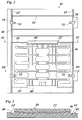
- Fig. 2
- ein Unterwerkzeug einer Vorrichtung, die zum Spritzgießen der Lordosensütze und zugleich zur Herstellung der Gittermatte dient, in der Draufsicht;
- Fig. 3
- einen Schnitt durch das Unterwerkzeug und ein zugehöriges Oberwerkzeug längs der Linie III-III in Figur 2;
- Fig. 4
- einen Schnitt durch das Unterwerkzeug und das Oberwerkzeug längs der Linie IV-IV in Figur 2;
- Fig. 5 - 8
- Schnitte entsprechend Figur 4 zur Illustration des Herstellungsverfahrens;
- Fig. 9 + 10
- Teilschnitte durch eine Vorrichtung zur Herstellung der Lordosenstütze und der Gittermatte gemäß einer anderen Ausführungsform des erfindungsgemäßen Verfahrens;
- Fig. 11
- einen Teil des Unterwerkzeugs der Vorrichtung nach Figuren 9 und 10 in der Draufsicht;
- Fig. 12
- einen Schnitt durch einen Verbindungsbereich zwischen einem Längsstab und einem Querstab der Gittermatte;
- Fig. 13
- Teile des Längsstabes und des Querstabes in der Draufsicht; und
- Fig. 14 - 16
- Teilschnitte durch eine Vorrichtung zur Herstellung der Lordosenstütze und der Gittermatte gemäß einer weiteren Ausführungsform des Verfahrens.
- Fig. 1
- a rear view of a mesh mat with a lumbar support according to the invention;
- Fig. 2
- a bottom tool of a device that is used for injection molding the lumbar support and at the same time for producing the grid mat, in plan view;
- Fig. 3
- a section through the lower tool and an associated upper tool along the line III-III in Figure 2;
- Fig. 4
- a section through the lower tool and the upper tool along the line IV-IV in Figure 2;
- 5 - 8
- Sections corresponding to Figure 4 to illustrate the manufacturing process;
- Fig. 9 + 10
- Partial sections through a device for producing the lumbar support and the lattice mat according to another embodiment of the method according to the invention;
- Fig. 11
- a part of the lower tool of the device according to Figures 9 and 10 in plan view;
- Fig. 12
- a section through a connecting region between a longitudinal bar and a cross bar of the grid mat;
- Fig. 13
- Parts of the longitudinal bar and the cross bar in plan view; and
- Figures 14-16
- Partial sections through a device for producing the lumbar support and the lattice mat according to a further embodiment of the method.
In Figur 1 ist eine Gittermatte 10 mit einer daran befestigten Lordosenstütze 12
gezeigt. Die Gittermatte 10 wird durch zwei an den Enden umgebogene Längsstäbe
14 gebildet, die durch mehrere sprossenartig angeordnete Querstäbe 16,
18 miteinander verbunden sind. Bei den Längsstäben 14 handelt es sich im gezeigten
Beispiel um Metalldrähte mit einem verhältnismäßig großen Querschnitt
und einer entsprechend hohen Biegesteifheit, während die Querstäbe 16, 18
durch dünnere Metalldrähte oder Stäbe aus Flachstahl gebildet werden. Jeder
der Längsstäbe 14 weist zwei Ausbiegungen 20 auf, die als Verankerungsstellen
für nicht gezeigte Zugfedern dienen, mit denen die Gittermatte 10 so im Rahmen
einer Rückenlehne eines Sitzes aufgehängt wird, daß sie im wesentlichen in der
Ebene der Rückenlehne in der Polsterung liegt und der Rückenlehne das geforderte
Maß an Steifheit und Nachgiebigkeit verleiht. Wahlweise können die
Längsstäbe auch als gelochte Flachbänder ausgebildet sein, deren Löcher zum
Einhängen der Zugfedern dienen.1 shows a
Die Lordosenstütze 12 weist ein im wesentlichen plattenförmiges Stützelement
22 aus Kunststoff auf, das auf beiden Seiten mehrere seitlich abstehende Finger
24 bildet und in der Mitte mit Durchbrüchen 26 versehen ist. Die Finger 24 sind
an der Rückseite durch angeformte Rippen 28 versteift. Durch rechtwinklig zu
den Rippen 28 verlaufende, jedoch unterbrochene Rippen 30 wird die Steifheit
des Stützelements 22 so eingestellt, daß es sich um eine Querachse elastisch
durchbiegen läßt und sich dabei in der Richtung senkrecht zur Zeichenebene in
Figur 1 mehr oder minder stark auswölbt. Ein im wesentlichen vertikal verlaufender
Hebel 32 ist mittig auf der Rückseite des Stützelements 22 angeordnet
und an seinem unteren Ende in einem Lager 34 schwenkbar an dem Stützelement
gelagert. Das obere Ende des Hebels 32 bildet eine Verankerungsstelle 36
für das Außenkabel eines nicht gezeigten Bowdenzuges. Eine Verankerungsstelle
38 für das zugehörige Innenkabel ist in der Nähe des oberen Randes des
Stützelements 22 angeordnet. Mit Hilfe des Bowdenzuges kann folglich das Stützelement
22 in vertikaler Richtung auf Kompression beansprucht werden, so
daß es sich in Richtung auf den Rücken des Benutzers durchwölbt.The
Zur Befestigung am Drahtgitter 10 weist das Stützelement an seinen oberen und
unteren Rändern je eine Verdickung 40 auf, in die jeweils einer der Querstäbe
18 eingebettet ist. Auf diese Weise ist das Stützelement 22 stabil und ausreißsicher
an der Gittermatte 10 gehalten. Wenn das Stützelement 22 durchgewölbt
wird und sich dabei in vertikaler Richtung verkürzt, werden die Querstäbe 18
elastisch durchgebogen. Da die Querstäbe in die Verdickungen 40 eingebettet
sind, können sie jedoch auch unter dieser Beanspruchung nicht von dem
Stützelement abgerissen werden.For attachment to the
Zur Herstellung des Stützelements 22 dient ein Spritzgießwerkzeug, dessen Unterwerkzeug
42 in Figur 2 gezeigt ist. Figur 3 zeigt einen Schnitt durch das Unterwerkzeug
42 und das zugehörige Oberwerkzeug 44.An injection mold, the lower tool of which is used to produce the
Das Unterwerkzeug 42 bildet einen Formhohlraum 22', mit dem die in Figur 1
sichtbare Rückseite des Stützelements 22 geformt wird. Wie Figur 3 zeigt, sind
die Bereiche des Formhohlraums 22', die die Finger 24 bilden, leicht nach oben
angewinkelt. Zu diesem Zweck bildet das Unterwerkzeug 42 schräg nach außen
ansteigende Plateaus 46. Außerhalb des Formhohlraums 22' und der Plateaus
46 weist das Unterwerkzeug 42 eine flache Oberfläche auf, die von Längsnuten
14' und Quernuten 16', 18' durchzogen ist. Die Längsnuten 14' sind so tief, daß
sie den gesamten Querschnitt der Längsstäbe 14 aufnehmen können. Die Quernuten
16', 18' sind dagegen flacher gehalten, so daß sie jeweils nur die untere
Hälfte des Querschnitts der Querstäbe 16, 18 aufnehmen, während die obere
Hälfte des Querschnitts durch entsprechende Nuten des Oberwerkzeugs 44 aufgenommen
wird. Die Quernuten 16', 18' werden auf der linken Seite in Figuren
2 und 3 durch einen Anschlag 48 begrenzt, während sie auf der rechten Seite
zum Rand des Unterwerkzeugs offen sind. Der Rand des Unterwerkzeugs bildet
hier eine Scherkante, an der die Querstäbe 16, 18 abgeschert werden können.
Die Quernuten 18' münden in Vertiefungen 40' des Formhohlraums 22', die den
Verdickungen 40 des Stützelements 22 entsprechen. The
Die Längsnuten 14' sind stellenweise zu Schablonen 50 erweitert, denen jeweils
ein Biegewerkzeug 52 zugeordnet ist. Die Längsstäbe 14 werden zunächst im
nicht gebogenen Zustand axial in die Längsnuten 14' eingeführt. Wahlweise
können die Längsstäbe dabei ähnlich wie die Querstäbe 16, 18 als Endlosmaterial
gegen einen Anschlag zugeführt und dann im Werkzeug abgelängt werden.
Anschließend werden die Biegewerkzeuge 52 nach außen gezogen, so daß die
Ausbiegungen 20 in den Längsstäben 14 gebildet werden. Die Biegewerkzeuge
52, die derselben Längsnut 14' zugeordnet sind, werden vorzugsweise zeitlich
nacheinander betätigt, damit die Längsstäbe 14 sich während des Biegevorgangs
axial in den Längsnuten 14 verschieben können, um den durch die Ausbiegungen
20 bedingten Mehrbedarf an Material auszugleichen. Anschließend werden
die Enden der Längsstäbe 14 in der in Figur 1 gezeigten Weise umgebogen.
Wahlweise kann auch dies mit Hilfe von Biegewerkzeugen geschehen, die in das
Unterwerkzeug 42 integriert sind.The longitudinal grooves 14 'are expanded in places to
Figur 4 zeigt einen Schnitt durch das geöffnete Spritzgießwerkzeug in Höhe einer
der Quernuten 18'. Die Längsstäbe 14 sind hier bereits in die Längsnuten eingeführt
und in der oben beschriebenen Weise gebogen werden. Am linken Rand
des Spritzgießwerkzeugs ist eine Schweißelektrode 54 gezeigt, die vertikalbeweglich
am Oberwerkzeug 44 gehalten ist und dazu dient, einen der Querstäbe 18
mit dem Längsstab 14 zu verschweißen. Entsprechende Schweißwerkzeuge sind
auch für die übrigen Querstäbe 16, 18 vorgesehen.Figure 4 shows a section through the opened injection mold at the level of a
of the transverse grooves 18 '. The
Am rechten Rand des Spritzgießwerkzeugs ist in Figur 4 ein Schneidmesser 56
gezeigt, das ebenfalls vertikalbeweglich am Oberwerkzeug 44 gehalten ist und
zusammen mit der Schneidkante des Unterwerkzeugs 42 dazu dient, die Querstäbe
16, 18 abzulängen.In FIG. 4, there is a cutting
Die Querstäbe 16, 18 werden als endlose Drähte von der rechten Seite des
Spritzgießwerkzeugs her zugeführt und jeweils bis zum Anschlag 48 in die Quernuten
16', 18' des Unterwerkzeugs eingeschoben.The cross bars 16, 18 are called endless wires from the right side of the
Injection mold supplied here and each up to the
Wie Figur 5 zeigt, wird anschließend das Spritzgießwerkzeug geschlossen, so
daß der Querstab 18 zwischen dem Unterwerkzeug 42 und dem Oberwerkzeug
44 in Position gehalten wird. Entsprechendes gilt auch für die in Figur 5 nicht
erkennbaren Querstäbe 16. Für die Querstäbe 18 gilt allerdings die Besonderheit,
daß sie sich frei durch das Innere der Vertiefungen 40' des Formhohlraums
erstrecken. As FIG. 5 shows, the injection mold is then closed, see above
that the
Anschließend wird das Schneidmesser 56 abgesenkt, um den Querstab 18 an
der Schneidkante des Unterwerkzeugs 42 abzuschneiden, wie in Figur 6 gezeigt
ist. Auf dieselbe Weise werden auch die übrigen Querstäbe 16, 18 abgelängt.
Oberhalb des Schneidmessers 56 wird dann eine weitere Schweißelektrode 54 in
Position gebracht. Wie Figur 7 zeigt, werden dann die Schweißelektroden 54 abgesenkt,
um den Querstab 18 und entsprechend auch die Querstäbe 16 an beiden
Enden mit den Längsstäben 14 zu verschweißen. Etwa gleichzeitig wird
Kunststoffschmelze in den Formhohlraum 22' eingespritzt, um das Stützelement
22 zu bilden. Dabei werden die Querstäbe 18 mit Kunststoffschmelze umspritzt
und in die Verdickungen 40 des Stützelements eingebettet. Nach dem Entformen
erhält man schließlich die in Figur 8 gezeigte Einheit aus Gittermatte 10
und Stützelement 22.Then the cutting
Eine abgewandelte Ausführungsform der Erfindung wird nachstehend anhand
der Figuren 9 bis 11 erläutert. Diese Ausführungsform unterscheidet sich von
dem zuvor beschriebenen Verfahren dadurch, daß die Querstäbe 16, 18 nicht an
die Längsstäbe angeschweißt werden, sondern an den Enden zu Ösen gebogen
werden, die die Längsstäbe fest umschlingen. Auch das Biegen der Ösen erfolgt
jedoch etwa zeitgleich mit dem Spritzgießvorgang. Zu diesem Zweck weisen das
Oberwerkzeug 44 und das Unterwerkzeug 42 jeweils an der Verbindungsstelle
zwischen dem Querstab 18 und dem Längsstab 14 Aussparungen in der Form
von Zylindersegmenten auf, die sich bei geschlossenem Werkzeug zu einem
kreiszylindrischen Hohlraum ergänzen, der auf den Längsstab 14 bzw. die zugehörige
Längsnut 14' des Unterwerkzeugs zentriert ist. Eine zylindrische Biegescheibe
58 ist drehbar in diesem Hohlraum gelagert und weist an ihrer dem
Querstab 18 zugewandten Stirnfläche einen kreissegmentförmigen Vorsprung
60 auf. In dem in Figur 9 gezeigten Zustand liegt dieser Vorsprung 60 ganz innerhalb
des Oberwerkzeugs 44. Der Querstab 18 wird in die zugehörige Quernut
18' eingeschoben, bis er mit seinem Ende an der Umfangsfläche des zylindrischen
Hohlraums anstößt.A modified embodiment of the invention is described below
of Figures 9 to 11 explained. This embodiment differs from
the previously described method in that the cross bars 16, 18 are not on
the longitudinal rods are welded, but bent at the ends to eyelets
that wrap tightly around the longitudinal bars. The eyelets are also bent
however at about the same time as the injection molding process. For this purpose, the
Die Biegescheibe 58 ist drehantreibbar. Zum Drehantrieb dient eine Zahnstange
62, die von der Seite her in einen nicht gezeigten Kanal des Unterwerkzeugs 42
eintaucht und mit einer auf der Umfangsfläche der Biegescheibe 58 ausgebildeten
Zahnung 64 kämmt. Diese Zahnung 64 ist in Figur 11 zu erkennen. Weiterhin
zeigt Figur 11, daß der Vorsprung 60 gegenüber dem Querstab 18 versetzt
ist, so daß er sich an dem Querstab vorbeidrehen kann. Eine Blattfeder 66, die
an der Stirnfläche des zylindrischen Hohlraums im Unterwerkzeug 42 angeordnet
ist, sorgt jedoch dafür, daß das Ende des Querstabes 18 etwas in Richtung
auf die Biegescheibe 58 abgelenkt wird, wenn der Querstab 18 in der in Figur 9
gezeigten Weise eingeführt wird. Wenn nun die Zahnstange 62 verschoben wird,
um die Biegescheibe 58 im Gegenuhrzeigersinn zu drehen, so wird das Ende des
Querstabes 18 von dem Vorsprung 60 erfaßt und zu einer den Längsstab 14 eng
umschließenden Öse 68 gebogen, wie in Figur 10 zu erkennen ist. Auf diese
Weise lassen sich die Querstäbe 18 und entsprechend auch die Querstäbe 16
während des Spritzgießvorgangs oder unmittelbar davor oder danach stabil an
den zugehörigen Längsstäben 14 befestigen.The
Wahlweise können die Verbindungsstellen zwischen den Querstäben 16, 18 und
den Längsstäben 14 jeweils mit einer Umhüllung 70 aus Kunststoff umspritzt
werden, wie in Figuren 12 und 13 gezeigt ist. Dies gilt entsprechend auch für die
durch Schweißen hergestellten Verbindungsstellen gemäß Figur 8. In demselben
Arbeitsgang können an die Längsstäbe 14 auch Verankerungsstellen 72 aus
Kunststoff angespritzt werden, die das Einhaken der erwähnten Zugfedern ermöglichen
und somit die in Figur 1 gezeigten Ausbiegungen 20 ersetzen. In Figur
13 bildet die Verankerungsstelle 72 eine Öse 74 auf der Innenseite des
Längsstabes 14, also auf der Seite, die zur Mitte der Gittermatte weist. Durch
diese Anordnung wird eine stabile Verankerung der Zugfeder ermöglicht, da das
hakenförmig gebogene Ende der Zugfeder, das in die Öse 74 eingreift, auch den
durch den Längsstab 14 verstärkten Teil der Verankerungsstelle umgreift.Optionally, the connection points between the cross bars 16, 18 and
the
In entsprechender Weise können je nach Bedarf auch andere Teile der Längsund Querstäbe mit Kunststoff umspritzt werden um zusätzliche Funktionsteile an der Gittermatte zu befestigen. Insbesondere ist es möglich, das Biegeverhalten der Gittermatte gezielt zu beeinflussen, indem die Drähte stellenweise mit mehr oder minder dicken Umhüllungen aus Kunststoff umspritzt werden und/oder die Querstäbe 16, 18 an geeigneten Stellen durch Abastandshalter aus Kunststoff verbunden werden.In a corresponding manner, other parts of the longitudinal and Cross bars are encapsulated with plastic around additional functional parts to attach to the grid mat. In particular, it is possible to change the bending behavior to influence the grid mat in a targeted manner by using the wires in places more or less thick plastic sheaths are overmolded and / or the cross bars 16, 18 are made at suitable points by means of spacers Plastic are connected.
Figuren 14 bis 16 illustrieren eine Möglichkeit, das Spritzgießen des Stützelements
22, das Biegen der Querstäbe 16, 18 und das Umspritzen der Verbindungsstellen
zwischen den Querstäben und den Längsstäben zu einem einzigen
Arbeitsgang zusammenzufassen. Zu diesem Zweck bilden das Oberwerkzeug 44
und das Unterwerkzeug 42 an jeder Verbindungsstelle zwischen den Längsstäben
14 und den Querstäben 18 (oder 16) einen Formhohlraum 76 für die Umhüllung
70. Gemäß Figur 14 wird der Querstab 18 bis zur Innenwand des Formhohlraums
76 durchgeschoben. Während der Längsstab 14 durch das Unterwerkzeug
42 in Position gehalten wird, wird im Oberwerkzeug 44 ein Schieber
78 abgesenkt, so daß das Ende des Querstabes 18 innerhalb des Formhohlraums
76 um den Längsstab 14 herum nach unten gebogen wird. Anschließend
wird, wie in Figur 15 gezeigt ist, ein Schieber 80 des Unterwerkzeugs waagerecht
nach innen gefahren, um das Ende des Querstabes 18 erneut abzuwinkeln, so
daß es zu einem den Längsstab 14 eng umschließenden Haken gebogen wird.
Anschließend werden die Schieber 78, 80 wieder so weit zurückgezogen, bis sie
mit der Innenfläche des Formhohlraums 76 bündig sind, und der Formhohlraum
wird mit Kunststoffschmelze ausgespritzt, um die Umhüllung 70 zu bilden.
Gleichzeitig kann auch das in Figuren 14 bis 16 nicht gezeigte Stützelement
22 gespritzt werden, in das die Querstäbe 18 eingebettet sind.Figures 14 to 16 illustrate one way of injection molding the
Wenn die Querstäbe 16, 18 an die Längsstäbe 14 angeschweißt werden, wie bei
dem zuerst beschriebenen Ausführungsbeispiel, so können die Schweißelektroden
analog zu dem in Figuren 14 bis 16 gezeigten Verfahren so ausgebildet werden,
daß sie im zurückgezogenen Zustand mit der Innenfläche des Formhohlraums
76 bündig sind, so daß auch in diesem Fall die Schweißpunkte mit einer
Umhüllung 70 umspritzt werden können. Zu Isolationszwecken muß die
Schweißelektrode allerdings in dem Oberwerkzeug 44 in einer isolierenden Hülse
geführt werden, deren Stirnfläche wiederum einen Teil der Wand des Formhohlraums
76 bildet.If the cross bars 16, 18 are welded to the
Claims (14)
Applications Claiming Priority (2)
| Application Number | Priority Date | Filing Date | Title |
|---|---|---|---|
| DE10110138A DE10110138A1 (en) | 2001-03-02 | 2001-03-02 | Method of making a lumbar support |
| DE10110138 | 2001-03-02 |
Publications (3)
| Publication Number | Publication Date |
|---|---|
| EP1236610A2 true EP1236610A2 (en) | 2002-09-04 |
| EP1236610A3 EP1236610A3 (en) | 2004-01-28 |
| EP1236610B1 EP1236610B1 (en) | 2008-04-30 |
Family
ID=7676108
Family Applications (1)
| Application Number | Title | Priority Date | Filing Date |
|---|---|---|---|
| EP02004411A Expired - Lifetime EP1236610B1 (en) | 2001-03-02 | 2002-02-26 | Method for making a lumbar support |
Country Status (3)
| Country | Link |
|---|---|
| US (1) | US7120984B2 (en) |
| EP (1) | EP1236610B1 (en) |
| DE (2) | DE10110138A1 (en) |
Cited By (2)
| Publication number | Priority date | Publication date | Assignee | Title |
|---|---|---|---|---|
| EP1955836A1 (en) * | 2007-02-09 | 2008-08-13 | L&P Swiss Holding Company | Method and apparatus for manufacturing a suspension pad and corresponding suspension pad |
| WO2009012844A1 (en) * | 2007-07-23 | 2009-01-29 | Fico Cables Lda | Suspension mat for a motor vehicle seat |
Families Citing this family (12)
| Publication number | Priority date | Publication date | Assignee | Title |
|---|---|---|---|---|
| DE10220028B4 (en) | 2002-05-04 | 2011-07-28 | Schwarzbich, Jörg, 33607 | Seat insert and method for its manufacture |
| EP1843914B1 (en) * | 2005-02-02 | 2009-09-23 | Schukra Gerätebau AG | Lumbar support and method for the production thereof |
| US7585027B2 (en) * | 2006-04-07 | 2009-09-08 | Schukra Of North America | Overmolded thin-profile lumbar support |
| KR100901568B1 (en) * | 2006-12-12 | 2009-06-08 | 현대자동차주식회사 | Manufacturing method for metal seperator of fuel cell |
| JP5621520B2 (en) * | 2010-11-05 | 2014-11-12 | トヨタ紡織株式会社 | Vehicle seat |
| US8684460B2 (en) | 2011-06-15 | 2014-04-01 | Brose Fahrzeugteile Gmbh & Co. Kg, Coburg | Backrest structure for a seat with lumbar support and curving element comprising a pre-tensioning connecting element |
| EP2939569B1 (en) * | 2014-05-02 | 2018-03-28 | Schukra Gerätebau GmbH | Method of producing a lumbar support device, lumbar support device and vehicle seat |
| KR101683976B1 (en) | 2014-08-12 | 2016-12-07 | 현대자동차주식회사 | Suspension assembly for vehicle seat and manufacturing method of the same |
| US11166450B2 (en) | 2016-11-02 | 2021-11-09 | Bird B Gone Llc | Devices and methods for repelling avian pests |
| US10926683B2 (en) * | 2018-04-12 | 2021-02-23 | Ts Tech Co., Ltd. | Conveyance seat |
| DE102018127626A1 (en) * | 2018-11-06 | 2020-05-07 | Faurecia Autositze Gmbh | Upholstery bearing for a vehicle seat |
| KR20230015637A (en) * | 2021-07-23 | 2023-01-31 | 주식회사 디에스시동탄 | Lumber support assembly |
Citations (1)
| Publication number | Priority date | Publication date | Assignee | Title |
|---|---|---|---|---|
| EP0780262A1 (en) | 1995-12-23 | 1997-06-25 | Jörg Schwarzbich | Device for attaching a support element to a wire grating |
Family Cites Families (38)
| Publication number | Priority date | Publication date | Assignee | Title |
|---|---|---|---|---|
| US2596993A (en) * | 1949-01-13 | 1952-05-20 | United Shoe Machinery Corp | Method and mold for covering of eyelets by plastic injection |
| BE539367A (en) * | 1954-06-29 | 1955-07-15 | ||
| DE1479974A1 (en) * | 1962-03-31 | 1969-07-17 | Basf Ag | Process for the production of impact-resistant plastic foam sheets |
| US3458931A (en) * | 1963-09-16 | 1969-08-05 | Western Electric Co | Method for molding terminals in workpieces |
| US3264034A (en) * | 1964-03-25 | 1966-08-02 | David E Lawson | Load bearing structure |
| GB1140261A (en) * | 1964-04-29 | 1969-01-15 | Elisa Berthelsen | Improvements in and relating to structural frames such as window frames |
| US3389461A (en) * | 1965-04-08 | 1968-06-25 | Ibm | Molded insulator base having embedded terminals and method of forming the same |
| US3391426A (en) * | 1965-10-22 | 1968-07-09 | Motorola Inc | Molding apparatus |
| GB1390379A (en) * | 1972-06-28 | 1975-04-09 | Serck Industries Ltd | Method of manufacturing hollow articles eg heat exchangers |
| US3860287A (en) * | 1972-08-28 | 1975-01-14 | Flex O Lators | Seating construction |
| US3991146A (en) * | 1974-04-01 | 1976-11-09 | Imperial Chemical Industries Limited | Method of encapsulating an insert in plastics material by injection molding |
| AT373199B (en) * | 1979-12-13 | 1983-12-27 | Schmied K G Silhouette Modellb | METHOD FOR THE PRODUCTION OF WORKPIECES, ESPECIALLY OF EYEWEAR BRACKETS |
| FR2532883B2 (en) * | 1982-09-14 | 1988-06-24 | Duret M & Fils | PROCESS FOR PRODUCING A SEAT ELEMENT BY MOLDING A FRAME ON A TRIM AND SEAT ELEMENT OBTAINED BY SAID METHOD |
| FR2534792B1 (en) * | 1982-10-25 | 1985-10-18 | Citroen Sa | SEAT WITH INTEGRATED SUSPENSION AND METHOD FOR MANUFACTURING THE FRAME OF THIS SEAT |
| US4722821A (en) * | 1983-12-30 | 1988-02-02 | The Boeing Company | Method of making a cascade basket for a thrust reverser |
| FR2572987B1 (en) * | 1984-09-21 | 1987-01-02 | Pont A Mousson | METHOD AND DEVICE FOR OVER-MOLDING A SURROUNDING OF PRECISE DIMENSIONS ON THE SURROUNDING OF A FLAT OR GALBED PART WITH DIMENSIONAL TOLERANCES |
| JPS6292817A (en) | 1985-10-18 | 1987-04-28 | Meihou Kinzoku Kogyosho:Kk | Molding of resin molded part having a plurality of inserts therein |
| DE3612576C1 (en) * | 1986-04-15 | 1987-06-19 | Preh Elektro Feinmechanik | Electrical component with a plastic jacket and method for its production |
| JPS6378717A (en) * | 1986-09-22 | 1988-04-08 | Fuji Xerox Co Ltd | Manufacture of composite member of metal plate and synthetic resin |
| JPH0780198B2 (en) * | 1987-08-27 | 1995-08-30 | 富士ゼロックス株式会社 | Method of manufacturing composite member by injection molding |
| JP2686761B2 (en) * | 1988-02-22 | 1997-12-08 | 株式会社山城精機製作所 | Mold device with insert bend mechanism |
| US5190803A (en) * | 1988-11-25 | 1993-03-02 | Bayer Aktiengesellschaft | Structural shell with reinforcing ribs connected via perforations |
| DE4023967C1 (en) * | 1990-07-27 | 1991-10-02 | Weisser Spulenkoerper Gmbh & Co Kg, 7086 Neresheim, De | |
| FR2666771B1 (en) * | 1990-09-19 | 1992-12-18 | Europ Sieges Automobiles | HEADREST, PARTICULARLY FOR VEHICLE SEAT. |
| US5564809A (en) * | 1991-03-07 | 1996-10-15 | Donnelly Technology, Inc. | Encapsulated shelf for refrigerated compartments |
| DE4405495C2 (en) * | 1994-02-21 | 1996-05-09 | Schuster Wilhelm | Backrest for seats with a shell and an adjustable lumbar support |
| US5609652A (en) * | 1994-04-13 | 1997-03-11 | Koito Manufacturing Co., Ltd. | Method of manufacturing a synthetic resin part integrally formed with metal members |
| FR2726334B1 (en) * | 1994-10-28 | 1997-01-17 | Cesa | FASTENER AND ITS APPLICATION TO THE JUNCTION OF THE WIRES OF A SEAT CUSHION SUPPORT SHEET |
| DE4444803C2 (en) * | 1994-12-15 | 1997-04-24 | Ameu Management Corp | Elastic arch element made of plastic with longitudinal and cross struts for an arch-adjustable lumbar support |
| DE29504287U1 (en) * | 1995-03-13 | 1995-05-11 | Bonke Christoph Dr | Individually adjustable headrest for seats with a backrest |
| US5971618A (en) * | 1996-05-26 | 1999-10-26 | Valu Engineering, Inc. | Flange bearing having reinforced molded housing |
| IT1284666B1 (en) * | 1996-07-16 | 1998-05-21 | Bruzolo Manifatt Gestind Mb | HEADREST FOR VEHICLE SEATS. |
| US5799548A (en) * | 1996-07-22 | 1998-09-01 | Lexmark International, Inc. | Frame with molded features |
| FR2759649B1 (en) * | 1997-02-17 | 1999-04-23 | Faure Bertrand Equipements Sa | MATTRESS SUPPORT SHEET OF A MOTOR VEHICLE SEAT |
| AT408064B (en) * | 1999-08-04 | 2001-08-27 | Schukra Berndorf Ges M B H | ANATOMICALLY MOLDABLE SUPPORT |
| DE19943890C1 (en) * | 1999-09-14 | 2001-02-15 | Faure Bertrand Sitztech Gmbh | Seat part of vehicle seat, with plastic board containing sockets clipped to underspringing structure |
| US6758522B2 (en) * | 2001-03-29 | 2004-07-06 | L&P Property Management Company | Apparatus and method for varying coefficients of friction in a variable apex back support |
| DE10220028B4 (en) * | 2002-05-04 | 2011-07-28 | Schwarzbich, Jörg, 33607 | Seat insert and method for its manufacture |
-
2001
- 2001-03-02 DE DE10110138A patent/DE10110138A1/en not_active Withdrawn
-
2002
- 2002-02-26 EP EP02004411A patent/EP1236610B1/en not_active Expired - Lifetime
- 2002-02-26 DE DE50212172T patent/DE50212172D1/en not_active Expired - Lifetime
- 2002-03-01 US US10/087,456 patent/US7120984B2/en not_active Expired - Fee Related
Patent Citations (1)
| Publication number | Priority date | Publication date | Assignee | Title |
|---|---|---|---|---|
| EP0780262A1 (en) | 1995-12-23 | 1997-06-25 | Jörg Schwarzbich | Device for attaching a support element to a wire grating |
Cited By (3)
| Publication number | Priority date | Publication date | Assignee | Title |
|---|---|---|---|---|
| EP1955836A1 (en) * | 2007-02-09 | 2008-08-13 | L&P Swiss Holding Company | Method and apparatus for manufacturing a suspension pad and corresponding suspension pad |
| WO2008095732A1 (en) * | 2007-02-09 | 2008-08-14 | L&P Swiss Holding Ag | Method and apparatus for manufacturing a suspension pad and corresponding suspension pad |
| WO2009012844A1 (en) * | 2007-07-23 | 2009-01-29 | Fico Cables Lda | Suspension mat for a motor vehicle seat |
Also Published As
| Publication number | Publication date |
|---|---|
| EP1236610B1 (en) | 2008-04-30 |
| US7120984B2 (en) | 2006-10-17 |
| DE10110138A1 (en) | 2002-09-05 |
| DE50212172D1 (en) | 2008-06-12 |
| US20020140124A1 (en) | 2002-10-03 |
| EP1236610A3 (en) | 2004-01-28 |
Similar Documents
| Publication | Publication Date | Title |
|---|---|---|
| EP0780262B1 (en) | Device for attaching a support element to a wire grating | |
| EP1501389B1 (en) | Seat insert and method for producing the same | |
| EP1236610B1 (en) | Method for making a lumbar support | |
| DE102008051072A1 (en) | Motor vehicle seat with lumbar support for an anti-whiplash system | |
| DE102008038851A1 (en) | Backrest frame for vehicle seat e.g. passenger seat, of motor vehicle, has frame bars comprising longitudinal sections, carriers and stabilization elements, which are fixed in position relative to each other by connections | |
| EP1194051A1 (en) | Method and device for producing brushes and brushes produced using the same | |
| EP3322614B1 (en) | Clip for securing a seat cover to a foam part of a seat cushion, foaming tool, production arrangement, and method for producing a foam part of a seat cushion | |
| WO2003097431A1 (en) | Lightweight component for bearing elements of motor vehicles | |
| WO2006105915A1 (en) | Device and method for regulating a lateral part of a seat | |
| DE102005016488A1 (en) | Part e.g. backseat-backrest, fixing device for e.g. motor vehicle body, has retaining unit movable between release and locking positions, and bending points allowing crossover of unit from locking position to crash-secured locking position | |
| EP3231572A1 (en) | Tool and method for manufacturing a foam article, and foam article | |
| DE3521897A1 (en) | EXTERNAL CUTTER FOR AN ELECTRIC SHAVER | |
| WO2015018912A1 (en) | Clip securing device, in particular for motor vehicles | |
| EP2689696A1 (en) | Mount for a suspension spring | |
| DE10109655B4 (en) | Headrest device | |
| DE102005050971A1 (en) | Crash-activated headrest for motor vehicle, has blocking part with opening for link from carrier structure, and release device which allows release of tension spring | |
| DE102007052960A1 (en) | Modular seat structure for motor vehicle, has backrest or seat frame with metal frame, where multiple longitudinal elements and transverse elements are arranged and connected to each other in perpendicular manner | |
| WO2016071403A1 (en) | Seat pan device having a composite material and method for production thereof | |
| DE10019798A1 (en) | Seat cover arrangement for motor vehicle's seat has cover section to which are fitted fastening elements comprising long, preferably flat, profiled section with fixing hooks for engaging in mating sections on moulded shell of seat | |
| DE2800261A1 (en) | Safety mounting for seat belt clasp - incorporates self-locking adjusting ratchets to permit length variation but holding firm in crash | |
| DE602004002252T2 (en) | Rack pressure piece for the steering device of a motor vehicle | |
| DE102005026733A1 (en) | Foaming die for forming headrest in motor vehicle seat, has pair of lateral die segments movably connected with lower die segment so as to be displaceable toward and away from respective two lateral sides of die | |
| EP3078519A1 (en) | Holder component with a special seal channel | |
| DE10351658B4 (en) | Gripping tool for the automated assembly of a seat | |
| DE20221092U1 (en) | Insert in the form of an elastic grid mat for the back rest of a seat comprises transverse members which consist of a plastic material and are injection molded onto the longitudinal members |
Legal Events
| Date | Code | Title | Description |
|---|---|---|---|
| PUAI | Public reference made under article 153(3) epc to a published international application that has entered the european phase |
Free format text: ORIGINAL CODE: 0009012 |
|
| AK | Designated contracting states |
Kind code of ref document: A2 Designated state(s): AT BE CH CY DE DK ES FI FR GB GR IE IT LI LU MC NL PT SE TR |
|
| AX | Request for extension of the european patent |
Free format text: AL;LT;LV;MK;RO;SI |
|
| PUAL | Search report despatched |
Free format text: ORIGINAL CODE: 0009013 |
|
| AK | Designated contracting states |
Kind code of ref document: A3 Designated state(s): AT BE CH CY DE DK ES FI FR GB GR IE IT LI LU MC NL PT SE TR |
|
| AX | Request for extension of the european patent |
Extension state: AL LT LV MK RO SI |
|
| 17P | Request for examination filed |
Effective date: 20040218 |
|
| AKX | Designation fees paid |
Designated state(s): DE ES FR GB IT SE |
|
| 17Q | First examination report despatched |
Effective date: 20061229 |
|
| GRAP | Despatch of communication of intention to grant a patent |
Free format text: ORIGINAL CODE: EPIDOSNIGR1 |
|
| GRAS | Grant fee paid |
Free format text: ORIGINAL CODE: EPIDOSNIGR3 |
|
| GRAA | (expected) grant |
Free format text: ORIGINAL CODE: 0009210 |
|
| AK | Designated contracting states |
Kind code of ref document: B1 Designated state(s): DE ES FR GB IT SE |
|
| REG | Reference to a national code |
Ref country code: GB Ref legal event code: FG4D Free format text: NOT ENGLISH |
|
| REF | Corresponds to: |
Ref document number: 50212172 Country of ref document: DE Date of ref document: 20080612 Kind code of ref document: P |
|
| PG25 | Lapsed in a contracting state [announced via postgrant information from national office to epo] |
Ref country code: ES Free format text: LAPSE BECAUSE OF FAILURE TO SUBMIT A TRANSLATION OF THE DESCRIPTION OR TO PAY THE FEE WITHIN THE PRESCRIBED TIME-LIMIT Effective date: 20080810 |
|
| PG25 | Lapsed in a contracting state [announced via postgrant information from national office to epo] |
Ref country code: SE Free format text: LAPSE BECAUSE OF FAILURE TO SUBMIT A TRANSLATION OF THE DESCRIPTION OR TO PAY THE FEE WITHIN THE PRESCRIBED TIME-LIMIT Effective date: 20080731 |
|
| ET | Fr: translation filed | ||
| PLBE | No opposition filed within time limit |
Free format text: ORIGINAL CODE: 0009261 |
|
| STAA | Information on the status of an ep patent application or granted ep patent |
Free format text: STATUS: NO OPPOSITION FILED WITHIN TIME LIMIT |
|
| 26N | No opposition filed |
Effective date: 20090202 |
|
| PG25 | Lapsed in a contracting state [announced via postgrant information from national office to epo] |
Ref country code: IT Free format text: LAPSE BECAUSE OF FAILURE TO SUBMIT A TRANSLATION OF THE DESCRIPTION OR TO PAY THE FEE WITHIN THE PRESCRIBED TIME-LIMIT Effective date: 20080430 |
|
| PGFP | Annual fee paid to national office [announced via postgrant information from national office to epo] |
Ref country code: FR Payment date: 20120214 Year of fee payment: 11 |
|
| PGFP | Annual fee paid to national office [announced via postgrant information from national office to epo] |
Ref country code: DE Payment date: 20120229 Year of fee payment: 11 |
|
| PGFP | Annual fee paid to national office [announced via postgrant information from national office to epo] |
Ref country code: GB Payment date: 20120203 Year of fee payment: 11 |
|
| GBPC | Gb: european patent ceased through non-payment of renewal fee |
Effective date: 20130226 |
|
| REG | Reference to a national code |
Ref country code: FR Ref legal event code: ST Effective date: 20131031 |
|
| REG | Reference to a national code |
Ref country code: DE Ref legal event code: R119 Ref document number: 50212172 Country of ref document: DE Effective date: 20130903 |
|
| PG25 | Lapsed in a contracting state [announced via postgrant information from national office to epo] |
Ref country code: FR Free format text: LAPSE BECAUSE OF NON-PAYMENT OF DUE FEES Effective date: 20130228 Ref country code: DE Free format text: LAPSE BECAUSE OF NON-PAYMENT OF DUE FEES Effective date: 20130903 Ref country code: GB Free format text: LAPSE BECAUSE OF NON-PAYMENT OF DUE FEES Effective date: 20130226 |