EP1236607A2 - Motor control system - Google Patents
Motor control system Download PDFInfo
- Publication number
- EP1236607A2 EP1236607A2 EP01000404A EP01000404A EP1236607A2 EP 1236607 A2 EP1236607 A2 EP 1236607A2 EP 01000404 A EP01000404 A EP 01000404A EP 01000404 A EP01000404 A EP 01000404A EP 1236607 A2 EP1236607 A2 EP 1236607A2
- Authority
- EP
- European Patent Office
- Prior art keywords
- motor
- torque
- current
- control system
- flux
- Prior art date
- Legal status (The legal status is an assumption and is not a legal conclusion. Google has not performed a legal analysis and makes no representation as to the accuracy of the status listed.)
- Withdrawn
Links
Images


Classifications
-
- B—PERFORMING OPERATIONS; TRANSPORTING
- B60—VEHICLES IN GENERAL
- B60L—PROPULSION OF ELECTRICALLY-PROPELLED VEHICLES; SUPPLYING ELECTRIC POWER FOR AUXILIARY EQUIPMENT OF ELECTRICALLY-PROPELLED VEHICLES; ELECTRODYNAMIC BRAKE SYSTEMS FOR VEHICLES IN GENERAL; MAGNETIC SUSPENSION OR LEVITATION FOR VEHICLES; MONITORING OPERATING VARIABLES OF ELECTRICALLY-PROPELLED VEHICLES; ELECTRIC SAFETY DEVICES FOR ELECTRICALLY-PROPELLED VEHICLES
- B60L15/00—Methods, circuits, or devices for controlling the traction-motor speed of electrically-propelled vehicles
- B60L15/02—Methods, circuits, or devices for controlling the traction-motor speed of electrically-propelled vehicles characterised by the form of the current used in the control circuit
- B60L15/025—Methods, circuits, or devices for controlling the traction-motor speed of electrically-propelled vehicles characterised by the form of the current used in the control circuit using field orientation; Vector control; Direct Torque Control [DTC]
-
- B—PERFORMING OPERATIONS; TRANSPORTING
- B60—VEHICLES IN GENERAL
- B60L—PROPULSION OF ELECTRICALLY-PROPELLED VEHICLES; SUPPLYING ELECTRIC POWER FOR AUXILIARY EQUIPMENT OF ELECTRICALLY-PROPELLED VEHICLES; ELECTRODYNAMIC BRAKE SYSTEMS FOR VEHICLES IN GENERAL; MAGNETIC SUSPENSION OR LEVITATION FOR VEHICLES; MONITORING OPERATING VARIABLES OF ELECTRICALLY-PROPELLED VEHICLES; ELECTRIC SAFETY DEVICES FOR ELECTRICALLY-PROPELLED VEHICLES
- B60L50/00—Electric propulsion with power supplied within the vehicle
- B60L50/10—Electric propulsion with power supplied within the vehicle using propulsion power supplied by engine-driven generators, e.g. generators driven by combustion engines
- B60L50/16—Electric propulsion with power supplied within the vehicle using propulsion power supplied by engine-driven generators, e.g. generators driven by combustion engines with provision for separate direct mechanical propulsion
-
- B—PERFORMING OPERATIONS; TRANSPORTING
- B60—VEHICLES IN GENERAL
- B60L—PROPULSION OF ELECTRICALLY-PROPELLED VEHICLES; SUPPLYING ELECTRIC POWER FOR AUXILIARY EQUIPMENT OF ELECTRICALLY-PROPELLED VEHICLES; ELECTRODYNAMIC BRAKE SYSTEMS FOR VEHICLES IN GENERAL; MAGNETIC SUSPENSION OR LEVITATION FOR VEHICLES; MONITORING OPERATING VARIABLES OF ELECTRICALLY-PROPELLED VEHICLES; ELECTRIC SAFETY DEVICES FOR ELECTRICALLY-PROPELLED VEHICLES
- B60L50/00—Electric propulsion with power supplied within the vehicle
- B60L50/50—Electric propulsion with power supplied within the vehicle using propulsion power supplied by batteries or fuel cells
-
- B—PERFORMING OPERATIONS; TRANSPORTING
- B60—VEHICLES IN GENERAL
- B60L—PROPULSION OF ELECTRICALLY-PROPELLED VEHICLES; SUPPLYING ELECTRIC POWER FOR AUXILIARY EQUIPMENT OF ELECTRICALLY-PROPELLED VEHICLES; ELECTRODYNAMIC BRAKE SYSTEMS FOR VEHICLES IN GENERAL; MAGNETIC SUSPENSION OR LEVITATION FOR VEHICLES; MONITORING OPERATING VARIABLES OF ELECTRICALLY-PROPELLED VEHICLES; ELECTRIC SAFETY DEVICES FOR ELECTRICALLY-PROPELLED VEHICLES
- B60L58/00—Methods or circuit arrangements for monitoring or controlling batteries or fuel cells, specially adapted for electric vehicles
- B60L58/30—Methods or circuit arrangements for monitoring or controlling batteries or fuel cells, specially adapted for electric vehicles for monitoring or controlling fuel cells
-
- B—PERFORMING OPERATIONS; TRANSPORTING
- B60—VEHICLES IN GENERAL
- B60L—PROPULSION OF ELECTRICALLY-PROPELLED VEHICLES; SUPPLYING ELECTRIC POWER FOR AUXILIARY EQUIPMENT OF ELECTRICALLY-PROPELLED VEHICLES; ELECTRODYNAMIC BRAKE SYSTEMS FOR VEHICLES IN GENERAL; MAGNETIC SUSPENSION OR LEVITATION FOR VEHICLES; MONITORING OPERATING VARIABLES OF ELECTRICALLY-PROPELLED VEHICLES; ELECTRIC SAFETY DEVICES FOR ELECTRICALLY-PROPELLED VEHICLES
- B60L2220/00—Electrical machine types; Structures or applications thereof
- B60L2220/10—Electrical machine types
- B60L2220/12—Induction machines
-
- B—PERFORMING OPERATIONS; TRANSPORTING
- B60—VEHICLES IN GENERAL
- B60L—PROPULSION OF ELECTRICALLY-PROPELLED VEHICLES; SUPPLYING ELECTRIC POWER FOR AUXILIARY EQUIPMENT OF ELECTRICALLY-PROPELLED VEHICLES; ELECTRODYNAMIC BRAKE SYSTEMS FOR VEHICLES IN GENERAL; MAGNETIC SUSPENSION OR LEVITATION FOR VEHICLES; MONITORING OPERATING VARIABLES OF ELECTRICALLY-PROPELLED VEHICLES; ELECTRIC SAFETY DEVICES FOR ELECTRICALLY-PROPELLED VEHICLES
- B60L2220/00—Electrical machine types; Structures or applications thereof
- B60L2220/10—Electrical machine types
- B60L2220/14—Synchronous machines
-
- Y—GENERAL TAGGING OF NEW TECHNOLOGICAL DEVELOPMENTS; GENERAL TAGGING OF CROSS-SECTIONAL TECHNOLOGIES SPANNING OVER SEVERAL SECTIONS OF THE IPC; TECHNICAL SUBJECTS COVERED BY FORMER USPC CROSS-REFERENCE ART COLLECTIONS [XRACs] AND DIGESTS
- Y02—TECHNOLOGIES OR APPLICATIONS FOR MITIGATION OR ADAPTATION AGAINST CLIMATE CHANGE
- Y02T—CLIMATE CHANGE MITIGATION TECHNOLOGIES RELATED TO TRANSPORTATION
- Y02T10/00—Road transport of goods or passengers
- Y02T10/60—Other road transportation technologies with climate change mitigation effect
- Y02T10/64—Electric machine technologies in electromobility
-
- Y—GENERAL TAGGING OF NEW TECHNOLOGICAL DEVELOPMENTS; GENERAL TAGGING OF CROSS-SECTIONAL TECHNOLOGIES SPANNING OVER SEVERAL SECTIONS OF THE IPC; TECHNICAL SUBJECTS COVERED BY FORMER USPC CROSS-REFERENCE ART COLLECTIONS [XRACs] AND DIGESTS
- Y02—TECHNOLOGIES OR APPLICATIONS FOR MITIGATION OR ADAPTATION AGAINST CLIMATE CHANGE
- Y02T—CLIMATE CHANGE MITIGATION TECHNOLOGIES RELATED TO TRANSPORTATION
- Y02T10/00—Road transport of goods or passengers
- Y02T10/60—Other road transportation technologies with climate change mitigation effect
- Y02T10/70—Energy storage systems for electromobility, e.g. batteries
-
- Y—GENERAL TAGGING OF NEW TECHNOLOGICAL DEVELOPMENTS; GENERAL TAGGING OF CROSS-SECTIONAL TECHNOLOGIES SPANNING OVER SEVERAL SECTIONS OF THE IPC; TECHNICAL SUBJECTS COVERED BY FORMER USPC CROSS-REFERENCE ART COLLECTIONS [XRACs] AND DIGESTS
- Y02—TECHNOLOGIES OR APPLICATIONS FOR MITIGATION OR ADAPTATION AGAINST CLIMATE CHANGE
- Y02T—CLIMATE CHANGE MITIGATION TECHNOLOGIES RELATED TO TRANSPORTATION
- Y02T10/00—Road transport of goods or passengers
- Y02T10/60—Other road transportation technologies with climate change mitigation effect
- Y02T10/7072—Electromobility specific charging systems or methods for batteries, ultracapacitors, supercapacitors or double-layer capacitors
-
- Y—GENERAL TAGGING OF NEW TECHNOLOGICAL DEVELOPMENTS; GENERAL TAGGING OF CROSS-SECTIONAL TECHNOLOGIES SPANNING OVER SEVERAL SECTIONS OF THE IPC; TECHNICAL SUBJECTS COVERED BY FORMER USPC CROSS-REFERENCE ART COLLECTIONS [XRACs] AND DIGESTS
- Y02—TECHNOLOGIES OR APPLICATIONS FOR MITIGATION OR ADAPTATION AGAINST CLIMATE CHANGE
- Y02T—CLIMATE CHANGE MITIGATION TECHNOLOGIES RELATED TO TRANSPORTATION
- Y02T90/00—Enabling technologies or technologies with a potential or indirect contribution to GHG emissions mitigation
- Y02T90/40—Application of hydrogen technology to transportation, e.g. using fuel cells
Definitions
- This invention relates to a motor control system and more particularly, to a motor control system for use within a vehicle having an electric motor and which efficiently and accurately controls the torque provided by the motor, effective to satisfy the vehicle's torque demands.
- automotive vehicles In order to reduce automotive emissions and the demand for fossil fuel, automotive vehicles have been designed which are powered by electric motors. Many of these vehicles use one or more sources of electrical power (e.g., fuel cells or batteries) to power an alternating current or "AC" induction motor, such as a three-phase motor.
- sources of electrical power e.g., fuel cells or batteries
- AC alternating current or "AC" induction motor
- a motor control system for use within a vehicle including an alternating current type electric motor, a direct current type electrical power supply, and at least one driver-operated control.
- the control system includes a torque control portion which receives torque commands from the at least one driver-operated control and which is effective to provide a torque current and a flux current based upon said received torque commands; a vector control portion which receives the torque current and said flux current and which is effective to provide a first voltage value and a second voltage value based upon the torque current and said flux current; and a space vector pulse-width modulating portion, which is coupled to the power supply and to said motor, which receives the first voltage value and said second voltage value and which delivers a multi-phase voltage signal to the motor, effective to cause said motor to accurately deliver the torque commands.
- a method for controlling an alternating current induction motor within a vehicle including direct current power supply, and at least one driver-operated control.
- the method includes the steps of receiving torque commands from the at least one driver-operated control; generating a torque current and a flux current based upon the received torque commands; generating a direct axis voltage and a quadrature axis voltage based upon the generated torque current and flux current; converting the direct axis voltage and the quadrature axis voltage into three-phase voltage pulse width modulated signal; and using the pulse width modulated signal and the direct current power supply to provide a three-phase voltage signal to the induction motor, effective to cause the induction motor to accurately deliver the torque commands.
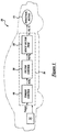
- FIG. 1 is a block diagram of a vehicle which includes a motor control system which is made in accordance with the teachings of a preferred embodiment of the present invention.
- FIG. 2 is a block diagram illustrating functionality of the torque control module used within the control system shown in Figure 1.
- Figure 3 is a block diagram illustrating one non-limiting embodiment of the torque current limitation function performed within the torque control module shown in Figure 2.
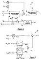
- Figure 4 is a diagram of a circuit used to model the motor in one non-limiting embodiment of the invention.
- Figure 5 is a block diagram illustrating the functionality of the vector control module used within the control system shown in Figure 1.
- Figure 6 is a block diagram illustrating the interrelationship between an adaptive control module, a flux observer module and a slip frequency calculation module used within the vector control module shown in Figure 5.
- Figure 7 is a block diagram illustrating the functionality of the slip frequency control module shown in Figure 5.
- Figure 8 is a block diagram illustrating the functionality of the flux observer module shown in Figure 5.
- Figure 9 is a block diagram illustrating the functionality of a current model portion of the flux observer module shown in Figure 8.
- Figure 10 is a block diagram illustrating the functionality of a voltage model portion of the flux observer module shown in Figure 8.
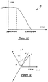
- Figure 11 is a graph illustrating a gain function used by the flux observer module shown in Figure 8.
- Figure 12 is a graphical representation illustrating the relationship between the motor phase currents iA, iB the two axis phase currents i ⁇ and i ⁇ .
- Figure 13 is a graphical representation illustrating the relationship between the phase axis ⁇ - ⁇ co-ordinates and the D-Q axis co-ordinates.
- Figure 14 is a diagram of a conventional circuit used to model an induction motor.
- Figure 15 is a flow diagram illustrating one non-limiting embodiment of the functionality of a proportional and integral control algorithm used within the vector control module shown in Figure 5.
- Figure 16 is a block diagram illustrating the functionality of the space vector PWM module used within the control system shown in Figure 1.
- Figure 17 is a graph of the phase voltage when the modulation amplitude (mi) equals 1.05.
- Figure 18 is a graph of the phase voltage when the modulation amplitude (mi) is greater than or equal to 1.10.
- Figure 19 is a graphical representation of the voltage vector with holding angle.
- Figure 20 is a table illustrating time compensation in three phases versus the current sector.
- Vehicle 10 including a highly efficient motor control system 16 which is made in accordance with the teachings of the preferred embodiment of the present invention.
- Vehicle 10 includes an electric induction motor 12 which selectively provides power and torque to the vehicle's drivetrain and an electrical energy storage device 14 which selectively provides electrical power to the motor 12 by way of control system 16.
- vehicle 10 may comprise a either a conventional electric or hybrid electric vehicle.
- electric motor 12 is a conventional electric induction motor which acts as a "power source” that provides torque and power to the vehicle drive train either exclusively (i.e., in an electric vehicle) or in addition to an internal combustion engine (i.e., in a hybrid electric vehicle).
- motor 12 operates by use of multi-phase (e.g., three-phase) AC electrical power.
- Electrical energy storage device 14 is a conventional source of electrical power, such as a battery or a fuel cell.
- storage device 14 provides DC-type electrical power and is coupled to control system 16 which is effective convert the DC-type electrical power into AC-type electrical power for use with motor 12.
- control system 16 includes one or more microprocessors or controllers as well as other chips, circuits and electrical components which co-operatively control the operation of induction motor 12.
- control system 16 receives signals and/or torque commands generated by vehicle operating systems and driver inputs (e.g., gear selection, accelerator position, and braking effort), and utilises the received torque commands to control the operation of induction motor 12, effective to cause the motor 12 to accurately and consistently deliver the driver-demanded torque to the vehicle's drivetrain.
- driver inputs e.g., gear selection, accelerator position, and braking effort
- control system 16 includes three primary functional blocks, modules or portions 18, 20 and 22, which co-operatively control the operation of motor 12 based upon the torque commands received from the vehicle controls. As described more fully and completely below, control system 16 includes a torque control portion or module 18, a vector control portion or module 20 and a space vector pulse-width-modulator "PWM" portion or module 22.
- PWM space vector pulse-width-modulator
- Module 18 is effective to generate a requested flux reference current, i_d_ref, and a requested torque reference current, i_q_ref, which are based upon the torque commands received from the vehicle controls.
- Functional block 24 represents an optimal flux reference map which is generated based upon the attributes of the specific induction motor 12 and the DC bus voltage of the electrical energy storage device 14.
- the reference map may be stored within a database table or matrix within controller 16.
- the reference map or table is used to select an optimal rotor flux level ⁇ * by indexing the table using the inputted torque and the synchronous speed ⁇ e of the motor.
- a conventional ramp function is applied to the flux current I d *, since flux cannot be changed dramatically, thereby yielding a flux reference current i_d_ref.
- the value of i_d_ref is further limited by the value of the torque reference current i_q_ref (i.e., i_d_ref should not be bigger than i_q_ref).
- the torque current I q * or i qs is calculated.
- FIG. 3 illustrates one non-limiting embodiment of the torque current limitation function performed by block 32.
- the inputs to block 32 are the requested or calculated torque reference current iq_ref; the flux reference current i_d_ref (I ds ); the error value ⁇ iq; and the below-defined inductance values lh (L h ) and l_sig (L ⁇ ).
- the outputs of block 32 are the torque reference current, i_q_ref (I qs ).
- Block 32 also uses several motor specific parameters or values including p_l_sig_h_cor which has a default value of eighty percent (80%); p_iabs_max (I s , max ); and inc_i_q.
- blocks 36 and 41 represent conventional limiting functions or algorithms
- block 38 represents a conventional ramping function
- block 43 corresponds to a conventional fuel cell or electrical power source current limitation controller. The following equations demonstrate the current limiting function provided by block 32.
- the calculated or determined flux reference current i_d_ref (I d ) and torque reference current i_q_ref (I q ) are communicated to the vector control module 20.
- Vector control is very sensitive to induction motor specific parameters. Hence, the D-Q reference voltage, current and slip frequency are all calculated using motor specific parameters. The correct motor parameters are essential for efficient control. Since different motors are installed in different vehicles, all parameters related to a specific motor have to be calibrated for the vehicle in which the motor is used.
- Module 20 further includes a flux observer (closed-loop current and voltage model via a speed-dependent gain) which is applied to estimate rotor flux.
- a current model is used during low speed operation, and a voltage model is used while motor is running at high speeds.
- the non-linear gain function which precisely controls the closed-loop observer bandwidth, permits a transition from the current to voltage model flux estimating attributes based on rotor speed.
- the gain function also allows for the implementation of an on-line parameter tuning in which the voltage model tunes the current model at higher speeds.
- the demanded D-Q voltages are the combination of dynamic and stable voltages.
- the dynamic voltages are calculated from the feedback currents of the motor.
- Two phase current controllers are also implemented within block 20 and provide a quick response to dynamic changes of vehicle condition.
- the stable voltage will dominant the control voltage when the vehicle is in stable condition and dynamic voltage decreases to around zero.
- the feedback currents are close to setting currents.
- the feedback D-Q current is transformed from the measured phase currents.
- the vector rotator function includes transformation of three phases to a-b axes, and a-b axes to D-Q axis.
- Vector control module 20 comprises several functional blocks, portions or modules 40 - 60.
- Block 40 represents a deadbeat adaptive control module or portion. Referring now to Figure 6, there is shown block 40 as it interrelates with blocks 42 and 44 in one non-limiting embodiment.
- the basic principle of the adaptive deadbeat controller 40 is to measure the rotor flux error for use as a feedback signal and to compute the slip frequency correction needed.
- the relationship between the rotor flux error and the slip gain error when detuning occurs (variation of parameters) is the key point in the implementation of the deadbeat adaptive controller.
- the two rotor flux components are effected by any amount of detuning due to change in the machine parameters.
- the function of block 40 is best described by the following equations.
- ⁇ qr L m i qs + L r i qr
- Figure 7 One non-limiting embodiment of the foregoing slip frequency calculation module 44 is illustrated in Figure 7, where the terms G_Prop, G_Int and Cor_Max are calibratable parameters.
- module 42 implements a closed-loop flux observer.
- the closed-loop observer combines a current model, which is represented by block 62, and a voltage model, which is represented by block 64, by use of a speed-dependent gain.
- the current model 62 serves as an implicit flux reference in which the model attributes are dominant at low speed.
- the current model has better performance at low speed and even at zero speed.
- the observer follows the voltage model rotor flux estimation attributes since it is less parameter sensitive.
- the rotor flux is estimated in the stationary frame since the observer is stable in that frame.
- the current model is derived from the induction motor ⁇ - ⁇ model dynamic equation referred to in the stationary reference frame.
- p ⁇ ⁇ r -r r i ⁇ r - ⁇ ⁇ r ⁇ r
- p ⁇ ⁇ r -r r i ⁇ r + ⁇ ⁇ r ⁇ r
- the current model 62 is best implemented in the rotor frame (i.e., the physical rotor frame, not the rotor flux frame) and thus requires transformation (e.g., see Eqs. 70 and 71) between the stationary and rotor frame using the measured rotor position.
- transformation e.g., see Eqs. 70 and 71
- the transformation to the rotor frame completely eliminates some undesirable cross coupling, which is speed-dependent, and makes the model independent of the rotor speed.
- the voltage model of the flux observer is based on the stationary frame.
- the current i ⁇ s is calculated by transforming the D-Q co-ordinates into ⁇ - ⁇ co-ordinates.
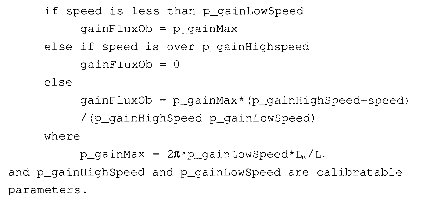
- the gain function which precisely controls the closed-loop observer bandwidth, permits a transition from the current to the voltage model flux estimating attributes based on rotor speed.
- One non-limiting embodiment of the gain function is illustrated by the graph 66 of Figure 11. The gain function operates as follows:
- block 46 comprises a rotor resistance adaption block or module which provides a rotor resistance measurement r r in the following manner.
- 0 r r *i qr +S* ⁇ e * ⁇ dr
- r r -S ⁇ e ⁇ dr /i qr
- Block 48 of vector control module 20 comprises an angle accumulator function.
- Block 48 provides an angle theta ( ⁇ e ) which is used to perform axis transformation or rotation (e.g., to transform from ⁇ - ⁇ axes to D-Q axes, voltage and current sector angle).
- Functional block or module 52 comprises a conventional encoder which is coupled to the motor 12 and which provides a signal to functional block or module 50. Block 50 utilises the signal from block 52 to perform a conventional speed measurement, thereby providing rotor speed ⁇ r .
- Functional block or module 54 takes a conventional current measurement from the motor and provides motor phase currents iA and iB to functional block or module 56.
- Block 56 converts the measured motor phase currents iA, iB into the two axis phase currents i ⁇ and i ⁇ .
- the amplitude of the resulting space vector will have the peak value of the phase current.
- a graphical representation of this relationship is shown in Figure 12.
- Block 56 also performs a transformation between the and ⁇ - ⁇ axis co-ordinates and the D-Q axis co-ordinates.
- the following function realises a transformation from the phase axis ⁇ - ⁇ co-ordinates into the D-Q axis co-ordinates.
- f d f ⁇ cos( ⁇ )+f ⁇ *sin( ⁇ )
- f q -f ⁇ sin( ⁇ )+f ⁇ *sin( ⁇ )
- a transformation from the phase axis D-Q co-ordinates into the ⁇ - ⁇ co-ordinates is performed as follows.
- f ⁇ f d cos( ⁇ )+f q *sin( ⁇ )
- f ⁇ f d sin ( ⁇ )+f q *cos ( ⁇ )
- Figure 13 A graphical representation of this transformation is shown in Figure 13.
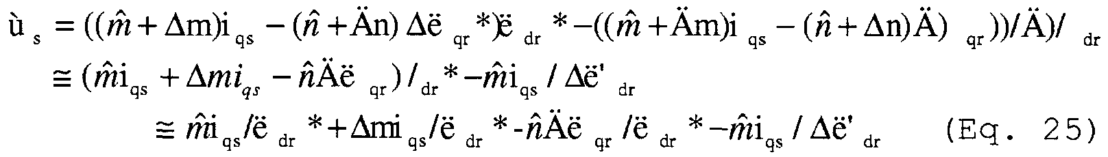
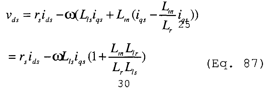
- Functional block or module 60 provides the reference voltage with respect to the D-Q axis.
- the function of module 60 is best described by the following equations.
- Figure 14 is a conventional induction motor equivalent circuit containing two series reactance normally referred to as the stator and rotor leakage reactance. Because this conventional circuit is not well-suited for vector control analysis, the modified equivalent circuit model 34 of Figure 4, in which the series reactance in the rotor branch is zero, is used to analyse the motor control algorithm. It is important to note that the stator current is shown divided into two components; one through the new magnetising branch called Id and one through the new rotor resistance called Iq. These are the two components of stator current which respectively control the rotor flux and torque.
- u_d_ref Rs*i_d_ref - f_stat*l_sig*i_q_ref
- u_d_ref Rs*i_q_ref + f_stat*l_sig*i_d_ref + f_stat*lh*i_d_ref
- blocks 58 of Figure 5 represent conventional proportional and integral (“PI") controllers or control modules.
- PI proportional and integral
- the PI control function provided by blocks 58 is illustrated in functional flow diagram 68 of Figure 15.
- the space vector pulse width modulating "PWM” module 22 activates the two closest voltage vectors and controls the active time for the motor control signal.
- the preferred embodiment of this space vector PWM module 22 is shown in Figure 16.
- Each of the active or inactive times (t0, t1 and t2) are calculated by module 22 from the demanded voltage and frequency. Additionally, the "dead time" of the IGBT device is compensated in this module. Since torque becomes critical during high speed, the below-described over-modulation and six step functions shown in block 72 are especially important in the present system. Particularly, the smooth transition between normal operation, over modulation and six step provided by the present system is important for vehicle applications.
- Functional block or module 70 represents a conventional DC bus, which is coupled to the source of DC electrical power and which provides DC bus voltage Vdc.
- Block 72 represents the over modulation and six step functions of module 22.
- the voltage is a sinusoidal waveform.
- the voltage vector is held at a vertex for particular time and then moves along the side of the hexagon for the rest of the switching period.
- the holding angle which depends on mi, controls the time interval the active switching state remains at the vertex.
- t1 TPWM*mi*sin ( ⁇ /3- ⁇ )
- t2 TPWM*mi*sin( ⁇ )
- the total time of t1 & t2 should not be more than TPWM
- t1' t1*TPWM/(t1+t2)
- the sector angle value ⁇ is between 0 and ⁇ /3.
- the following sector angle values provide the following values for t1, t2, and t0.
- the phase voltage is shown in Figure 18.
- a modulation ratio is calculated within block 72 when the motor operates at over modulation mode and mi is higher than the set point (MI_LINEAR + p_delta_mi) of over modulation. Otherwise the ratio is equal to 100%.
- Block 74 represents the calculation of t0, t1 and t2 and the voltage vectors.
- Block 76 is a conventional digital signal processing ("DSP") register which receives the t2, t1, t0 and voltage vector values from block 74 and which converts the values into three phase voltage values.
- Block 78 represents a conventional IGBT device ("IGBT”) which uses the received three phase values in a conventional manner to convert the DC voltage into a three phase voltage signal which is provided to induction motor 12.
- DSP digital signal processing
- IGBT device IGBT device
- Block 80 represents a conventional cartesian to polar co-ordinate transformation function.
- block 82 of space vector PWM module 22 provides time compensation for the IGBT device.
- tComp is the time compensation. The time period is used to compensate the PWM time according to the angle of current vector.
- the table shown in Figure 20 illustrates the time in three phases versus the current sector.
- control system 16 provides extremely accurate and efficient control of motor 12 by use of torque control module 18, vector control module 20 and space vector PWM module 22. It is understood that the invention is not limited by the exact construction or method illustrated and described above, but that various changes and/or modifications may be made without departing from the spirit and/or the scope of the inventions.
Landscapes
- Engineering & Computer Science (AREA)
- Power Engineering (AREA)
- Transportation (AREA)
- Mechanical Engineering (AREA)
- Life Sciences & Earth Sciences (AREA)
- Sustainable Development (AREA)
- Sustainable Energy (AREA)
- Control Of Ac Motors In General (AREA)
- Electric Propulsion And Braking For Vehicles (AREA)
- Control Of Electric Motors In General (AREA)
Abstract
Description
Lr=Lm+Lir where Lir is the leakage inductance for the rotor.


The sector angle: α<π/6
Claims (9)
- A motor control system for use within a vehicle including an alternating current type electric motor, a direct current type electrical power supply, and at least one driver-operated control, said control system comprising:a torque control portion which receives torque commands from said at least one driver-operated control and which is effective to provide a torque current and a flux current based upon said received torque commands;a vector control portion which receives said torque current and said flux current and which is effective to provide a first voltage value and a second voltage value based upon said torque current and said flux current; anda space vector pulse-width modulating portion, which is coupled to said power supply and to said motor, which receives said first voltage value and said second voltage value and which uses said first and second voltage values to deliver a multi-phase voltage signal to said motor, effective to cause said motor to accurately deliver said torque commands.
- The motor control system of claim 1 wherein said multi-phase voltage signal comprises a three-phase voltage signal.
- The motor control system of either claim 1 or claim 2 wherein said power supply comprises a fuel cell.
- The motor control system of either claim 1 or claim 2 wherein said power supply comprises a battery.
- The motor control system of any one of the preceding claims wherein said first voltage value is a direct axis voltage value and said second voltage value is a quadrature axis voltage value.
- The motor control system of any one of the preceding claims wherein said space vector pulse-width modulating portion comprises a IGBT device which delivers said multi-phase voltage signal to said motor.
- The motor control system of any one of the preceding claims wherein said vehicle is an electric vehicle.
- The motor control system of any one of claims 1 to 6 wherein said vehicle is a hybrid electric vehicle.
- A motor control system for use in combination with a vehicle of the type having an alternating current induction motor which selectively delivers torque to said vehicle, a power supply, and at least one driver-operated control, said motor control system comprising:a first portion which is communicatively coupled to and receives torque commands from said at least one driver operated control, said first portion being effective to generate a flux current and a torque current based upon said received torque commands and a synchronous speed value of said motor;a second portion which receives said generated flux current and torque current, said second portion being effective to generate a direct axis voltage and a quadrature axis voltage based upon said generated flux and torque currents and at least one motor specific parameter; anda third portion which receives said direct and quadrature axis voltages and which converts said direct and quadrature axis voltages into a three phase voltage signal which is communicated to said induction motor, effective to cause said motor to accurately deliver said torque commands.
Applications Claiming Priority (2)
| Application Number | Priority Date | Filing Date | Title |
|---|---|---|---|
| US09/653,654 US6388419B1 (en) | 2000-09-01 | 2000-09-01 | Motor control system |
| US653654 | 2000-09-01 |
Publications (2)
| Publication Number | Publication Date |
|---|---|
| EP1236607A2 true EP1236607A2 (en) | 2002-09-04 |
| EP1236607A3 EP1236607A3 (en) | 2003-09-24 |
Family
ID=24621782
Family Applications (1)
| Application Number | Title | Priority Date | Filing Date |
|---|---|---|---|
| EP01000404A Withdrawn EP1236607A3 (en) | 2000-09-01 | 2001-08-24 | Motor control system |
Country Status (4)
| Country | Link |
|---|---|
| US (1) | US6388419B1 (en) |
| EP (1) | EP1236607A3 (en) |
| JP (1) | JP2002142500A (en) |
| CA (1) | CA2354326A1 (en) |
Cited By (4)
| Publication number | Priority date | Publication date | Assignee | Title |
|---|---|---|---|---|
| WO2009126288A3 (en) * | 2008-04-10 | 2010-01-07 | Tesla Motors, Inc. | Weighted field oriented motor control |
| WO2009126291A3 (en) * | 2008-04-10 | 2010-01-14 | Tesla Motors, Inc. | Voltage estimation feedback of overmodulated signal |
| CN102582460A (en) * | 2012-02-17 | 2012-07-18 | 湖南南车时代电动汽车股份有限公司 | Method for setting target torque of motor applicable to pure electric vehicle |
| JP2023177081A (en) * | 2022-06-01 | 2023-12-13 | 株式会社豊田自動織機 | Parameter calculation device, parameter calculation method, and program |
Families Citing this family (43)
| Publication number | Priority date | Publication date | Assignee | Title |
|---|---|---|---|---|
| US6566840B1 (en) * | 2002-02-11 | 2003-05-20 | Ford Global Technologies, Inc. | Method and system for self-calibration of an induction machine drive |
| US20050046375A1 (en) * | 2002-07-31 | 2005-03-03 | Maslov Boris A. | Software-based adaptive control system for electric motors and generators |
| US20040070363A1 (en) * | 2002-10-10 | 2004-04-15 | Bardsley David J. | Integrated induction starter/generator system with hybrid control for high speed generation and idle speed smoothing |
| US7197390B2 (en) * | 2003-03-13 | 2007-03-27 | Wavecrest Laboratories Llc | Electric vehicle with adaptive cruise control system |
| US7495403B2 (en) * | 2004-03-30 | 2009-02-24 | Continental Automotive Systems Us, Inc. | Method, apparatus and article for vibration compensation in electric drivetrains |
| CN101091119B (en) * | 2005-04-01 | 2010-08-18 | 三菱电机株式会社 | tram control device |
| JP4364845B2 (en) * | 2005-07-05 | 2009-11-18 | 本田技研工業株式会社 | Control device for fuel cell vehicle and control method for fuel cell vehicle |
| JP4727354B2 (en) * | 2005-09-07 | 2011-07-20 | 本田技研工業株式会社 | Control device for electric vehicle |
| JP2007159368A (en) * | 2005-12-08 | 2007-06-21 | Toyota Motor Corp | Control device for motor drive system |
| JP4381408B2 (en) * | 2006-02-17 | 2009-12-09 | 株式会社デンソー | Electric vehicle control device |
| US7577545B2 (en) * | 2007-05-29 | 2009-08-18 | Hamilton Sundstrand Corporation | Method and system for estimating rotor angular position and rotor angular velocity at low speeds or standstill |
| US8604709B2 (en) | 2007-07-31 | 2013-12-10 | Lsi Industries, Inc. | Methods and systems for controlling electrical power to DC loads |
| US8903577B2 (en) | 2009-10-30 | 2014-12-02 | Lsi Industries, Inc. | Traction system for electrically powered vehicles |
| US7598683B1 (en) | 2007-07-31 | 2009-10-06 | Lsi Industries, Inc. | Control of light intensity using pulses of a fixed duration and frequency |
| CN100557943C (en) * | 2008-06-13 | 2009-11-04 | 株洲南车时代电气股份有限公司 | A Synchronous Modulation Method Based on Space Vector |
| KR100986001B1 (en) | 2008-12-22 | 2010-10-06 | 재단법인대구경북과학기술원 | Operation Method of Pulse Width Modulation Driver Module for Controlling Pulse Width Modulation Unit based on ATVSAR |
| DE102009021823A1 (en) * | 2009-05-18 | 2010-12-09 | Bombardier Transportation Gmbh | Overcurrent limiting in the control of converter-fed three-phase machines |
| US8154228B2 (en) * | 2009-06-10 | 2012-04-10 | Kollmorgen Corporation | Dynamic braking for electric motors |
| US8339093B2 (en) * | 2009-06-11 | 2012-12-25 | Eaton Corporation | System and method of dynamic regulation of real power to a load |
| US8232760B2 (en) * | 2009-06-11 | 2012-07-31 | Easton Corporation | System and method of dynamic regulation of real power to a load |
| US9148083B2 (en) | 2009-06-11 | 2015-09-29 | Eaton Corporation | System and method of dynamic regulation of real power to a load |
| ITRM20090334A1 (en) * | 2009-06-26 | 2010-12-27 | Oxygen S P A | METHOD FOR THE CONTROL OF THE ADVANCEMENT SPEED IN SCOOTER WITH ELECTRIC PROPULSION |
| US8676524B2 (en) * | 2010-05-06 | 2014-03-18 | I-Shou University | System for computing machine parameters of an induction machine |
| KR101382305B1 (en) * | 2010-12-06 | 2014-05-07 | 현대자동차주식회사 | Motor control device for hybrid vehicle |
| CN102223138B (en) * | 2011-06-27 | 2013-04-03 | 株洲南车时代电气股份有限公司 | Motor synchronous modulation method and control system thereof |
| US9209736B2 (en) * | 2011-10-03 | 2015-12-08 | General Electric Company | System and method for traction motor control |
| US10020761B2 (en) | 2012-09-20 | 2018-07-10 | Ford Global Technologies, Llc | Electric motor position signal synchronized operation |
| US9479099B2 (en) * | 2013-01-30 | 2016-10-25 | Infineon Technologies Ag | Stator flux magnitude and direction control strategies for permanent magnet synchronous motors |
| US9444382B2 (en) * | 2013-01-30 | 2016-09-13 | Infineon Technologies Ag | Optimized field oriented control strategies for permanent magnet synchronous motors |
| US9966889B2 (en) * | 2013-05-12 | 2018-05-08 | Infineon Technologies Ag | Optimized control for synchronous motors |
| US9847745B1 (en) | 2013-05-21 | 2017-12-19 | Robert Bosch Gmbh | Simulation of a field-oriented stator voltage of a stator of an asynchronous machine steadily required during operation |
| WO2014187749A2 (en) * | 2013-05-21 | 2014-11-27 | Robert Bosch Gmbh | Rotary-encoder-free, field-oriented control of the rotational speed of an asynchronous machine that can be operated by means of a graduated voltage |
| US10521519B2 (en) * | 2013-07-23 | 2019-12-31 | Atieva, Inc. | Induction motor flux and torque control with rotor flux estimation |
| US11418140B2 (en) | 2013-07-23 | 2022-08-16 | Atieva, Inc. | Induction motor flux and torque control |
| US9344026B2 (en) * | 2013-07-23 | 2016-05-17 | Atieva, Inc. | Induction motor flux and torque control |
| KR101583951B1 (en) * | 2014-07-02 | 2016-01-08 | 현대자동차주식회사 | Control device and method for improving inverter output of green car |
| KR101601444B1 (en) * | 2014-07-04 | 2016-03-21 | 현대자동차주식회사 | Device and method for controlling inverter of motor driving system |
| JP6448995B2 (en) * | 2014-11-25 | 2019-01-09 | Ntn株式会社 | Electric vehicle motor drive device |
| KR101684538B1 (en) * | 2015-06-18 | 2016-12-08 | 현대자동차 주식회사 | Inverter control method for hybrid vehicle |
| US9849806B1 (en) | 2016-06-01 | 2017-12-26 | Ford Global Technologies, Llc | Current based six step control |
| US9973120B1 (en) * | 2017-04-20 | 2018-05-15 | GM Global Technology Operations LLC | Control of six step pulse width modulation with flux weakening |
| WO2020049673A1 (en) * | 2018-09-06 | 2020-03-12 | 株式会社Fuji | Electric motor control device and electric motor control method |
| CN113179072B (en) * | 2021-05-13 | 2022-08-19 | 山东中科先进技术有限公司 | Angle compensation method and system for permanent magnet synchronous motor controller |
Family Cites Families (12)
| Publication number | Priority date | Publication date | Assignee | Title |
|---|---|---|---|---|
| JPH05176418A (en) * | 1991-03-25 | 1993-07-13 | Hitachi Ltd | Electric vehicle controller |
| US5285862A (en) * | 1992-03-16 | 1994-02-15 | Toyota Jidosha Kabushiki Kaisha | Power supply system for hybrid vehicles |
| JPH07298698A (en) * | 1994-04-21 | 1995-11-10 | Hitachi Ltd | Induction motor controller |
| JPH08140202A (en) * | 1994-11-07 | 1996-05-31 | Hitachi Ltd | Electric vehicle protection device and protection method |
| JP3487952B2 (en) * | 1995-04-14 | 2004-01-19 | 株式会社日立製作所 | Drive device and drive control method for electric vehicle |
| US5739664A (en) * | 1996-02-05 | 1998-04-14 | Ford Global Technologies, Inc. | Induction motor drive controller |
| JP4372235B2 (en) * | 1996-08-29 | 2009-11-25 | トヨタ自動車株式会社 | Fuel cell system and electric vehicle |
| WO1998011663A1 (en) * | 1996-09-13 | 1998-03-19 | Hitachi, Ltd. | Device for controlling induction motor and method of controlling the same |
| US5994881A (en) * | 1997-10-07 | 1999-11-30 | Hitachi, Ltd. | Control apparatus for a synchronous generator system and a hybrid-type electric vehicle using it |
| JP3527071B2 (en) * | 1997-07-04 | 2004-05-17 | 株式会社日立製作所 | Electric vehicle control device |
| US5959431A (en) * | 1997-10-03 | 1999-09-28 | Baldor Electric Company | Method and apparatus for instability compensation of V/Hz pulse width modulation inverter-fed induction motor drives |
| JP3297371B2 (en) * | 1998-03-12 | 2002-07-02 | 株式会社東芝 | Electric car control device |
-
2000
- 2000-09-01 US US09/653,654 patent/US6388419B1/en not_active Expired - Lifetime
-
2001
- 2001-07-30 CA CA002354326A patent/CA2354326A1/en not_active Abandoned
- 2001-08-24 EP EP01000404A patent/EP1236607A3/en not_active Withdrawn
- 2001-08-31 JP JP2001263133A patent/JP2002142500A/en not_active Withdrawn
Cited By (6)
| Publication number | Priority date | Publication date | Assignee | Title |
|---|---|---|---|---|
| WO2009126288A3 (en) * | 2008-04-10 | 2010-01-07 | Tesla Motors, Inc. | Weighted field oriented motor control |
| WO2009126291A3 (en) * | 2008-04-10 | 2010-01-14 | Tesla Motors, Inc. | Voltage estimation feedback of overmodulated signal |
| US7821224B2 (en) | 2008-04-10 | 2010-10-26 | Tesla Motors, Inc. | Voltage estimation feedback of overmodulated signal for an electrical vehicle |
| CN102582460A (en) * | 2012-02-17 | 2012-07-18 | 湖南南车时代电动汽车股份有限公司 | Method for setting target torque of motor applicable to pure electric vehicle |
| CN102582460B (en) * | 2012-02-17 | 2015-06-24 | 湖南南车时代电动汽车股份有限公司 | Method for setting target torque of motor applicable to pure electric vehicle |
| JP2023177081A (en) * | 2022-06-01 | 2023-12-13 | 株式会社豊田自動織機 | Parameter calculation device, parameter calculation method, and program |
Also Published As
| Publication number | Publication date |
|---|---|
| US6388419B1 (en) | 2002-05-14 |
| CA2354326A1 (en) | 2002-03-01 |
| EP1236607A3 (en) | 2003-09-24 |
| JP2002142500A (en) | 2002-05-17 |
Similar Documents
| Publication | Publication Date | Title |
|---|---|---|
| EP1236607A2 (en) | Motor control system | |
| RU2391767C2 (en) | Device and method for control of drive system from electric motor | |
| US10804831B2 (en) | Control apparatus for alternating-current rotary electric machine | |
| US7800331B2 (en) | Method and system for operating an electric motor coupled to multiple power supplies | |
| US8427087B2 (en) | Control device for AC motor | |
| US9762152B2 (en) | Motor control system for executing drive control of an alternating-current motor | |
| US8281886B2 (en) | Electric motor control device, drive device and hybrid drive device | |
| US9602040B2 (en) | Apparatus for controlling first and second rotary electric machines | |
| US9077275B2 (en) | Rotor position estimating device, electric motor control system and rotor position estimating method | |
| US9413281B2 (en) | Apparatus for controlling AC motor | |
| US10778130B2 (en) | Control apparatus for alternating-current rotary electric machine | |
| US7012389B2 (en) | Electric drive control apparatus, electric drive control method and program thereof | |
| US6194865B1 (en) | Control method and system for electric rotary machine | |
| US9077278B2 (en) | AC motor control apparatus | |
| US9281774B2 (en) | Motor control system | |
| EP2268500B1 (en) | Voltage estimation feedback of overmodulated signal | |
| JP7114968B2 (en) | electric motor drive | |
| US9007009B2 (en) | Control apparatus for AC motor | |
| US10099563B2 (en) | Power supply device for vehicle and method for controlling the same | |
| US10594240B2 (en) | Control device for alternating current motor | |
| US20140225540A1 (en) | Control apparatus for ac motor | |
| US20160181960A1 (en) | Motor control apparatus and motor control method | |
| US9705445B2 (en) | Apparatus for controlling alternating-current rotary electric machines | |
| US6518718B2 (en) | Speed electromotive force phase control system adapted to low speed | |
| US10536101B2 (en) | Control device for alternating current motor |
Legal Events
| Date | Code | Title | Description |
|---|---|---|---|
| PUAI | Public reference made under article 153(3) epc to a published international application that has entered the european phase |
Free format text: ORIGINAL CODE: 0009012 |
|
| AK | Designated contracting states |
Kind code of ref document: A2 Designated state(s): AT BE CH CY DE DK ES FI FR GB GR IE IT LI LU MC NL PT SE TR |
|
| AX | Request for extension of the european patent |
Free format text: AL;LT;LV;MK;RO;SI |
|
| PUAL | Search report despatched |
Free format text: ORIGINAL CODE: 0009013 |
|
| AK | Designated contracting states |
Kind code of ref document: A3 Designated state(s): AT BE CH CY DE DK ES FI FR GB GR IE IT LI LU MC NL PT SE TR |
|
| AX | Request for extension of the european patent |
Extension state: AL LT LV MK RO SI |
|
| 17P | Request for examination filed |
Effective date: 20040315 |
|
| RAP1 | Party data changed (applicant data changed or rights of an application transferred) |
Owner name: BALLARD POWER SYSTEMS CORPORATION |
|
| AKX | Designation fees paid |
Designated state(s): DE FR GB |
|
| RAP1 | Party data changed (applicant data changed or rights of an application transferred) |
Owner name: SIEMENS VDO ELECTRIC DRIVES INC. |
|
| RAP1 | Party data changed (applicant data changed or rights of an application transferred) |
Owner name: SIEMENS VDO AUTOMOTIVE CORPORATION |
|
| 17Q | First examination report despatched |
Effective date: 20080131 |
|
| STAA | Information on the status of an ep patent application or granted ep patent |
Free format text: STATUS: THE APPLICATION IS DEEMED TO BE WITHDRAWN |
|
| 18D | Application deemed to be withdrawn |
Effective date: 20110301 |