EP1235970B1 - Automatic door assembly with video imaging device - Google Patents
Automatic door assembly with video imaging device Download PDFInfo
- Publication number
- EP1235970B1 EP1235970B1 EP00982486A EP00982486A EP1235970B1 EP 1235970 B1 EP1235970 B1 EP 1235970B1 EP 00982486 A EP00982486 A EP 00982486A EP 00982486 A EP00982486 A EP 00982486A EP 1235970 B1 EP1235970 B1 EP 1235970B1
- Authority
- EP
- European Patent Office
- Prior art keywords
- door
- video
- imaging device
- video data
- data signal
- Prior art date
- Legal status (The legal status is an assumption and is not a legal conclusion. Google has not performed a legal analysis and makes no representation as to the accuracy of the status listed.)
- Expired - Lifetime
Links
- 238000003384 imaging method Methods 0.000 title claims description 121
- 238000013459 approach Methods 0.000 claims abstract description 56
- 238000001514 detection method Methods 0.000 claims abstract description 55
- 238000000034 method Methods 0.000 claims description 42
- 230000004044 response Effects 0.000 claims description 26
- 238000012545 processing Methods 0.000 claims description 25
- 230000005355 Hall effect Effects 0.000 claims description 22
- 230000008569 process Effects 0.000 claims description 21
- 238000004891 communication Methods 0.000 claims description 16
- 238000012544 monitoring process Methods 0.000 claims description 9
- 238000009434 installation Methods 0.000 claims description 8
- 230000015654 memory Effects 0.000 claims description 5
- 230000000007 visual effect Effects 0.000 abstract description 2
- 230000007704 transition Effects 0.000 description 14
- 230000008859 change Effects 0.000 description 13
- 230000006870 function Effects 0.000 description 9
- 230000008713 feedback mechanism Effects 0.000 description 7
- 239000000969 carrier Substances 0.000 description 5
- 238000012423 maintenance Methods 0.000 description 5
- 230000003213 activating effect Effects 0.000 description 4
- 230000000712 assembly Effects 0.000 description 4
- 238000000429 assembly Methods 0.000 description 4
- 238000013461 design Methods 0.000 description 3
- 230000000694 effects Effects 0.000 description 3
- 230000000737 periodic effect Effects 0.000 description 2
- 230000008439 repair process Effects 0.000 description 2
- 241000238631 Hexapoda Species 0.000 description 1
- 241001465754 Metazoa Species 0.000 description 1
- 241000555745 Sciuridae Species 0.000 description 1
- 230000009471 action Effects 0.000 description 1
- 238000007664 blowing Methods 0.000 description 1
- 238000010276 construction Methods 0.000 description 1
- 230000007423 decrease Effects 0.000 description 1
- 230000003247 decreasing effect Effects 0.000 description 1
- 238000001914 filtration Methods 0.000 description 1
- 230000007257 malfunction Effects 0.000 description 1
- 238000011017 operating method Methods 0.000 description 1
- 230000003287 optical effect Effects 0.000 description 1
- 238000012552 review Methods 0.000 description 1
- 239000004065 semiconductor Substances 0.000 description 1
- 239000007787 solid Substances 0.000 description 1
Images


Classifications
-
- H—ELECTRICITY
- H04—ELECTRIC COMMUNICATION TECHNIQUE
- H04N—PICTORIAL COMMUNICATION, e.g. TELEVISION
- H04N7/00—Television systems
- H04N7/18—Closed-circuit television [CCTV] systems, i.e. systems in which the video signal is not broadcast
- H04N7/183—Closed-circuit television [CCTV] systems, i.e. systems in which the video signal is not broadcast for receiving images from a single remote source
- H04N7/186—Video door telephones
-
- E—FIXED CONSTRUCTIONS
- E05—LOCKS; KEYS; WINDOW OR DOOR FITTINGS; SAFES
- E05F—DEVICES FOR MOVING WINGS INTO OPEN OR CLOSED POSITION; CHECKS FOR WINGS; WING FITTINGS NOT OTHERWISE PROVIDED FOR, CONCERNED WITH THE FUNCTIONING OF THE WING
- E05F15/00—Power-operated mechanisms for wings
- E05F15/70—Power-operated mechanisms for wings with automatic actuation
- E05F15/73—Power-operated mechanisms for wings with automatic actuation responsive to movement or presence of persons or objects
-
- H—ELECTRICITY
- H04—ELECTRIC COMMUNICATION TECHNIQUE
- H04N—PICTORIAL COMMUNICATION, e.g. TELEVISION
- H04N7/00—Television systems
- H04N7/18—Closed-circuit television [CCTV] systems, i.e. systems in which the video signal is not broadcast
- H04N7/183—Closed-circuit television [CCTV] systems, i.e. systems in which the video signal is not broadcast for receiving images from a single remote source
-
- E—FIXED CONSTRUCTIONS
- E05—LOCKS; KEYS; WINDOW OR DOOR FITTINGS; SAFES
- E05F—DEVICES FOR MOVING WINGS INTO OPEN OR CLOSED POSITION; CHECKS FOR WINGS; WING FITTINGS NOT OTHERWISE PROVIDED FOR, CONCERNED WITH THE FUNCTIONING OF THE WING
- E05F15/00—Power-operated mechanisms for wings
- E05F15/70—Power-operated mechanisms for wings with automatic actuation
- E05F15/73—Power-operated mechanisms for wings with automatic actuation responsive to movement or presence of persons or objects
- E05F2015/767—Power-operated mechanisms for wings with automatic actuation responsive to movement or presence of persons or objects using cameras
-
- E—FIXED CONSTRUCTIONS
- E05—LOCKS; KEYS; WINDOW OR DOOR FITTINGS; SAFES
- E05Y—INDEXING SCHEME ASSOCIATED WITH SUBCLASSES E05D AND E05F, RELATING TO CONSTRUCTION ELEMENTS, ELECTRIC CONTROL, POWER SUPPLY, POWER SIGNAL OR TRANSMISSION, USER INTERFACES, MOUNTING OR COUPLING, DETAILS, ACCESSORIES, AUXILIARY OPERATIONS NOT OTHERWISE PROVIDED FOR, APPLICATION THEREOF
- E05Y2900/00—Application of doors, windows, wings or fittings thereof
- E05Y2900/10—Application of doors, windows, wings or fittings thereof for buildings or parts thereof
- E05Y2900/13—Type of wing
- E05Y2900/132—Doors
Definitions
- the present invention relates to an automatic door assembly for controlling access through a door opening. More particularly, the present invention relates to an automatic door assembly that incorporates the use of a video imaging device that detects the approach of persons and objects to the door assembly and responsively signals the operator of the door assembly to open the door panel(s) thereof.
- an automatic door assembly that automatically opens when a person approaches the doorway to permit entrance/exit therethrough.
- These automatic door assemblies typically use microwave doppler or active and passive infrared (IR) sensors to detect the motion of a person approaching the door.
- IR infrared
- some automatic door assemblies use pressure sensitive mats or electric eyes to determine the presence of a person in front of the door panel(s) thereof. Irrespective of which kind of sensor is used, when a sensor determines that a person is approaching the doorway, the controller of the door assembly responsively signals a door operator thereof to move the door panel(s) to the open position thereof to permit passage therethrough.
- the surveillance imaging device is mounted at a vantage point that provides a view of the persons travelling through the doorway while, at the same time, sensors on the door assembly are also monitoring the areas adjacent to or within the doorway to detect the presence of motion indicative of persons travelling through the doorway.
- the building owner is paying for the costs of two systems that function to some extent to monitor a doorway.
- the imaging device that monitors the doorway and the door assembly itself are typically installed by different companies, thereby increasing installation costs.
- a door operating system having a variable programmed operating method to satisfy certain preselected criteria. It is said that a primary purpose of the system is to improve on a door system and a method of operating a door system such that the opening and closing of the door system are controlled individually as a function of the detected traffic situation' and as a function of ambient conditions.
- the door system can be programmed individually for a given building in such a way as to offer access or passage for people and/or vehicles with as little draught as possible on the one hand, while on the other hand presenting the least possible hindrance to such access or passage and also adapting precisely to the prevailing needs of the building at all times.
- One or more video cameras are connected to an appropriate video image processing system to ascertain how many people and/or vehicles are approaching the door system.
- other detection media may also be provided such as weight identification or speed detection.
- US-A-6,084,367 discloses an automatic door assembly for installation at a doorway formed through a wall of a building, said door assembly comprising: a frame assembly constructed and arranged to be mounted to the building wall at the doorway thereof; a door panel constructed and arranged to be mounted to said frame assembly for movement between a closed position wherein said door panel is positioned in covering relation over the doorway to prevent persons and objects from travelling therethrough and an open position wherein said door panel is moved out of said covering relation to permit persons and objects to travel through the doorway; a door controlling system comprising: (i) a video imaging device constructed and arranged to be mounted in a viewing position wherein said imaging device monitors a field of view that encompasses at least an approach area located adjacent to the doorway, said video imaging device being adapted to transmit an internal video data signal comprising information representative of said field of view; and (ii) a detection system comprising a video signal processor that communicates with said video imaging device, said video signal processor being adapted to receive said internal video data signal from said
- an automatic door assembly characterised in that said door controlling system is adapted to transmit an external video data signal comprising information representative of the field of view of said imaging device to a video processing device that is capable of (a) receiving the video data signal and (b) processing the video data signal into a form suitable for displaying images that are visually representative of the imaging device's field of view, thereby enabling said door controlling system to be in communication with the aforesaid video processing device so that the video device can process the external video data signal into a form suitable for displaying images that are visually representative of the field of view of said video imaging device including at least the approach area adjacent said doorway.
- a method of operating a doorway apparatus comprising an automatic door assembly comprising: a frame assembly; a door panel mounted to the frame assembly for movement between a closed position, and an open position; a door controlling system comprising a video imaging device mounted in a viewing position to monitor a field of view that encompasses at least an approach area located adjacent to the automatic door assembly, and a detection system comprising a video signal processor in communication with the video imaging device; and a door operator connected to the door panel and in communication with the detection system; the method comprising: monitoring the field of view encompassing at least the approach area by the video imaging device receiving images of the field of view; transmitting, from the video imaging device to the video signal processor, an internal video data signal comprising information representative of the images received by the video imaging device; processing the internal video data signal by the processor to determine whether a person or object has entered the approach area; in response to the processor determining that a person or object has entered the approach area, transmitting a
- the video imaging device is a digital video imaging device.
- the door controlling system may further comprise a door controller in communication with both said signal processor and said door operator and said video signal processor may be adapted to generate a detection signal and transmit the detection signal to the controller in response to determining that a person or object has entered the approach area; said door controller being adapted to generate and transmit said door opening signal to said operator in response to receiving said detection signal; said controller being adapted to (a) monitor the positioning of said door panel between said open and closed positions thereof and (b) select a speed at which said operator moves said door panel based on the said positioning of said door panel and in response to control said operator to move said door panel at said selected speed by varying an amplitude or frequency of said door operating signal.
- the processor determines whether a person or object has entered the approach area by detecting motion of the person or object within the approach area.
- the said door panel may be a single sliding door panel movable generally rectilinearly within a threshold area of the doorway, or the door panel may be one of a pair of sliding door panels movable generally rectilinearly towards and away from one another within a threshold area of the doorway.
- a combination comprising: a building having a wall with a doorway formed therethrough; an automatic door assembly generally as set out above with the frame assembly mounted to the building wall at the doorway thereof, and a video processing device as set out above communicated to the said door assembly's controlling system.
- the video processing device may be a video data storing device that (a) processes and stores the information comprising the external video data signal and (b) enables the stored information to be subsequently retrieved for displaying images that are representative of the field of view of said video imaging device including at least the approach area adjacent said doorway.
- said video processing device is a video display device that processes the information comprising the external video data signal and displays images that are visually representative of the field of said video imaging device including at least the approach area adjacent said doorway.
- the imaging device is provided by a digital or analog video camera.
- the detection system may comprise both the processor and a standard door controller.
- the door controller would be of the type known in the art that is capable of monitoring the position of the door panel structure via a feedback mechanism and varying the amplitude or frequency of the door opening signal to control the speed at which the door operator opens the door panel(s). For example, it is usually desired to move the door panel relatively slowly at or near the fully opened and closed positions thereof and relatively faster in the middle of its travel path.
- the processor generates a detection signal and transmits the same to the controller.
- the controller responsively generates and transmits the appropriate door opening signal to the operator based on the position of the door panel. In fact, if the door panel is already in the fully open position thereof, the controller may ignore the detection signal and not transmit any door opening signal to save on wear and tear of the operator.
- the functions of the controller may be built into the processor.
- the video device may include a video display device such as a video monitor or a video data storing device that stores the information for later retrieval and review in conjunction with a video display monitor.
- a video display device such as a video monitor or a video data storing device that stores the information for later retrieval and review in conjunction with a video display monitor.
- the door assembly of the present invention provides the functions and advantages of a video imaging device and the door controlling functions of a typical door assembly into one convenient package. This convenience can be greatly appreciated by establishments that monitor their doorways with video surveillance because the provision of the video imaging device on the door assembly eliminates the need for separately purchasing and installing a video imaging device for monitoring the doorway.
- the door controlling system comprises a video imaging device constructed and arranged to be mounted in a viewing position wherein the imaging device monitors a field of view that encompasses at least a door panel travel area through which the door panel moves during movement thereof between the open and closed positions.
- the door controlling system also comprises a detection system comprising a video signal processor that communicates with the video imaging device.
- the video signal processor is adapted to receive the video data signal from the imaging device and to process the information comprising the internal video data signal to determine whether a person or object is in the door panel structure travel area.
- the detection system is adapted such that the processor ignores the movement of the door panel within the door panel travel area so that the door panel is not determined by the processor to be a person or object in the predetermined area.
- the detection system is also adapted to responsively transmit a door opening signal in response to the processor thereof determining that a person or object is within the door panel travel area.
- a door operator is constructed and arranged to be connected to the door panel and adapted to communicate with the detection system. The door operator is constructed and arranged to move the door panel from the closed position thereof to the open position thereof through the door panel travel area responsive to receiving the door opening signal.
- the assembly of this aspect of the invention is advantageous because the travel area of the door panel can be properly monitored by an imaging device without the costs and complexities associated with continually activating and deactivating multiple sensors as in the prior art arrangements.
- FIG 1 is a perspective view of a sliding door assembly embodying the present invention, generally indicated at 100, mounted within a doorway 102 of a wall 104 of a building 106, the remainder of the building being cut-away around the doorway 102.
- the door assembly 100 comprises a frame assembly, generally indicated at 108, that mounts within the doorway 102.
- the frame assembly 102 comprises a header 110 that houses the door operator (shown schematically at 16 in Fig. 2) and the door controlling system (shown schematically at 10 in Fig. 2) that controls the door operator 16, which system 10 will be described in more detail hereinbelow.
- the frame assembly 108 also comprises a pair of non-sliding panels 112 that cover opposing sides of the doorway 102.
- the door assembly 100 further comprises door panel structure in the form of a pair of sliding door panels 114, 116 that move rectilinearly between open and closed positions.
- the door panels 114, 116 are positioned in covering relation over the portions of the doorway 102 that are not covered by the non-sliding panels 112 to prevent the travel of persons and objects therethrough.
- the door panels 114, 116 are moved out of covering relation with respect to the doorway 102 to permit the travel of persons and objects through the doorway 102.
- the door operator 16 may be of any known construction, such as hydraulic or electromechanical, and connects to door panel carriers (not shown) that are housed inside the header 110. Each of the door panels 114, 116 are individually mounted to these door panel carriers and the carriers roll or slide in a rectilinear manner within the header 110 toward or away from one another to provide the door panels 114, 116 with their movement between the open and closed positions thereof.
- the use of such door panel carriers is well-known in the art and will not be detailed herein.
- the door operator 16 operates to move the door panel carriers away and towards one another to effect the movement of the door panels 114, 116 between the open and closed positions thereof.
- the door assembly 100 also comprises a video imaging device (shown schematically at 26 in Fig. 2) housed within a video camera 120 that is mounted in a viewing position to the outwardly facing surface of the header 110.
- the imaging device 26 of the camera 120 has a field of view as demarcated by lines 122 that encompasses an approach area 124 disposed adjacent to the doorway 102. This enables the imaging device 26 to monitor approach area 124. It is contemplated that the imaging device's field of view may also encompass the doorway 102 itself (i.e., the threshold area). This enables the device 26 to monitor both the approach area 124 for persons approaching the doorway and the threshold area within the doorway 102 itself for persons stopped and standing therein. The role and function of the imaging device 26 is explained in further detail hereinbelow.
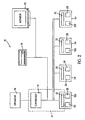
- FIG. 2 schematically illustrates the general concepts and arrangement of the present embodiment of the invention.
- the door controlling system generally indicated at 10, is housed within the header 110 (Fig. 1) and communicates with the door operator, which is indicated schematically in this Fig. 2 at 16.
- the door controlling system 10 has one or more video imaging units, each indicated at 26 and housed within video cameras 120 similar to video camera 120 shown in Fig. 1.
- the door controlling system 10 also comprises a motion detection sub-system 31.
- This sub-system 31 comprises one or more video camera processor 32 and a door controller 14 that communicates with the operator 16.
- Each of the cameras 120 houses one of said processors 32 that is adapted to generate a motion detection signal and transmit the signal to the controller 14 in a manner that is described in further detail hereinbelow.
- the door controller 14 is adapted to generate a door opening signal and transmit the signal to the operator 16 in a manner that is described in further detail hereinbelow.
- each of the cameras 120 has an electronic video imaging device 26, preferably in the form of a digital video imaging device.
- the signal processor 32 receives and processes video data from the video imaging device 26. More specifically, the video imaging device 26 generates and transmits an internal video data signal comprising information representative of its field of view. This internal video data signal is received by the processor 32 and processed or evaluated to determine whether a person or object has entered into the approach area. The specific way in which the processor 32 makes this determination will be described in further detail below.
- the processor 32 determines that a person or object has entered the approach area 24, the processor 32 generates and transmits a motion detection signal to the controller 14, which in turn transmits a door opening signal to the door operator 16 (assuming .the door panels 114, 116 are not already in the open position thereof).
- the controller 14 may be of any type known in the art. Such a controller 14 would treat the motion detection signal from the processor 32 in the same manner as it would if it were a motion detection signal that was transmitted from other well known motion or presence detection systems, such as IR or microwave doppler sensors. As is well-known in the art, the controller 14 monitors the position of the door and uses that information to vary the amplitude or frequency of the door opening signal to affect faster or slower movement of the door panel(s). For example, it is usually desirable that the door operator 16 moves the door panel(s) slower at or near the fully opened and closed positions thereof. The controller 14 monitors the position of the door panel(s) using the same well-known Hall effect sensor arrangement that is described hereinbelow. The controller 14 may also be adapted to wait a predetermined period of time after the processor has ceased generating and transmitting the motion detection signal and then generate and transmit a door closing signal to the operator 16.
- the processor 32 processes or evaluates the information comprising the internal video data signal in accordance with known algorithms in order to detect movement of a person or object in or into the imaging device's the field of view. For example, an image frame taken at one time may be stored and compared with a subsequent image frame taken at a later time. In the case of a digital image, a pixel-by-pixel comparison may be performed between the two images. In that case, if a pixel has a different image value in the subsequent image than in the earlier image, a change in pixel value is tallied for that pixel. If a large object, such as a person, moves between the time of the earlier image, and the subsequent image, then a large number of pixels will register as having different values between the two images.
- a detection threshold value is set.
- the processor 32 responsively treats that as motion and transmits the motion detection signal to the controller 14.
- the detection threshold value can be set at a higher value to eliminate detection of small objects, such as paper blown through the field of view by the wind or other such debris, or small animals such as insects, small birds, and squirrels that may move through the field of view.
- the detection threshold value is set to a value at which motion of a small child is detected.
- the detection threshold may be set such that partially solid objects such as wire frame or. plastic shopping carts are detected.
- the processor 32 filters out the background image and distinguishes certain moving objects from a person or people approaching the automatic door.
- background objects will typically be stationary on a time scale which is long compared to the time it takes for a person to walk into the view of a video imaging device, and to pass through the automatic door and travel out of the field of view of the opposing video imaging device.
- blowing paper or leaves may blow into the field of view, and then remain steady for many minutes, hours or even days.
- Objects may be rearranged and moved, for example, relocating a trashcan within the field of view. Changing weather conditions, such as snow, may present relatively fixed background images.
- each of the imaging devices 26 generates and transmits an internal video data signal to its associated processor 32.
- Each processor 32 processes or evaluates its respective signal to determine whether a person or object has entered into any of the areas monitored by the imaging devices 26.
- that processor 32 determines that a person or object has entered one of these monitored areas 24, that processor 32 generates and transmits a motion detection signal to the controller 14, which in turn transmits a door opening signal to the door operator 16 (assuming the door panels 114, 116 are not already in the open position thereof).
- a black-and-white digital camera that employs CCD elements for image pickup is used to provide the video imaging device(s) 26.
- Color video imaging devices may be used in other embodiments.
- embodiments of the invention are not limited to only digital imaging devices. Analog video cameras may be used in other embodiments of the invention.
- a camera 120 may include LED indicators 28 that provide information on the operational status of a master camera and its imaging device during the installation, operation and/or maintenance thereof.
- the camera(s) 120 are selectively attached to portions of an automatic door assembly and/or structures immediately adjacent thereto.
- the number of cameras 120 used and their particular placement will depend on the particular type of automatic door assembly and, in some cases, on the size of the door.
- the most common applications may be categorized as sliding doors, swinging doors, and bi-fold doors. In the case of swing doors, there are four common types of swing doors encountered: uni-directional single door, uni-directional double door, bi-directional single door, and bi-directional double door.
- the video imaging device(s) 26 of the door controlling system are also communicated to a remotely located external video device that is capable of processing a video data signal received from a video imaging device 26 into a form that is suitable for displaying images that are visually representative of the imaging device's field of view.
- a remotely located external video device that is capable of processing a video data signal received from a video imaging device 26 into a form that is suitable for displaying images that are visually representative of the imaging device's field of view.
- the external video signals from a plurality of imaging devices 26 may be transmitted to a single video device for simultaneous viewing or storage and subsequent viewing with the fields of view being shown in "split screen" fashion.
- This external video data signal may be transmitted to the external video device directly from the imaging device 26 that generates it in parallel with the processor or it may be transmitted to the external video device indirectly through the video processor 32 in series therewith.
- the external video data signal (which may be digital or analog) comprises information that is visually representative of the imaging device's field of view.
- the external video device may be a video data storing device, shown at 18, that is capable of processing a video data signal and storing the same for later use in conjunction with a display device, thereby allowing events taking place in the camera's field of view to be reviewed at a later time.
- the video data storing device 18 is preferably a high-capacity unit, but may generally be selected from a wide range of available semiconductor storage devices, magnetic storage devices, or optical storage media, such as flash memories, hard drives, removable magnetic media, recordable CD, recordable DVD disks, or standard VHS VCR tape, for example.
- a further preferred feature of the video data storing device 18 is that it is adapted to record only when motion is detected in the field of view of the imaging device 26 from which the external video data signal is derived.
- each processor 32 is in communication with the activating device of the storing device 18 and transmits the same motion detection signal that it transmits to the controller 14.
- the controller 14 may be in communication with the activating device of the storing device 18 so that the controller 14 activates the storage device 18 responsive to receiving the motion detection signal from one of the processors.
- the storing device 18 normally stays inactive and does not record or otherwise store the external video signal transmitted thereto.
- the external video device may be a video display device in the form of one or more video monitors, shown at 20.
- the monitor 20 may be viewed by security personnel to track the travel of persons and objects through the doorway 102.
- the monitor 20 may be located at a remote service location and be in communication with the door controlling system 10 via a digital or analog network. This could enable a service or repair technician to visually verify the operational condition of the door assembly (assuming an imaging device on the door assembly has pertinent portions such as the door panel(s) within its field of view) prior to travelling to the location of the door assembly 100. This can reduce the need for travelling of the repair technician to handle problems that he could easily instruct on-site persons to handle over the telephone while viewing their activities on the monitor 20.
- the processor 32 distinguishes between particular "known" moving objects and other moving objects.
- the processor 32 recognizes detection of the moving door panel(s) themselves and ignores such movement. That is, the processor 32 detects the motion of a door panel within a field of view of an imaging device, but does not generate a motion detecting signal in response to such motion.
- a look-up table of data is generated in correlation with known motion and positions of the door panel(s).
- sensors are placed on components, which move in correlation with the motion of the door.
- a suitable feedback mechanism that may be used is disclosed in U.S. Patent No. 4,565,029.
- the feed back mechanism may also have two Hall effect transistors positioned on a circuit board that is fastened to the rear of the motor housing used to effect opening and closing of the door.
- the motor shaft protrudes through the rear of the motor housing where a small magnetically-charged disk having four poles spaced 90° from one another is fastened to the motor shaft.
- the magnetic disk rotates causing four magnetic fields, each created by one of the poles and alternating between positive and negative, to pass alongside the two Hall effect transistors.
- the transistors are positioned substantially along a circular arc relative to the axis of rotation 221 ⁇ 2° out-of-phase from each other.
- a power source is connected to the transistors, and the transistors act as switches that close momentarily each time a magnetic pole passes alongside the two transistors. This results in two separate periodic waveforms from the transistor-magnetic field configuration, each of which is generated by a respective one of the sensors.
- the two waveforms are substantially identical squarewaves having two values that may be referred to a high and low and are 221 ⁇ 2° out-of-phase with each other due to the relative positioning of the transistors along the path of rotation.
- the two waveforms are transmitted to the processor 32 either directly or indirectly via the controller 14.
- the two waveforms output from the feedback mechanism are utilized by the processor to determine the position, direction, and speed of the moving door. Generally, the position and direction of motion of the door are of greater interest than the speed of the door.
- FIGURE 4 is a schematic drawing illustrating an example of such a feedback mechanism. It should be understood that this arrangement is only provided as an illustrative example and is not intended to be limiting.
- the motor has a motor housing 74 and a rotating shaft 76 protruding through the rear of the motor housing 74.
- Two Hall effect transistors 78 and 80 are disposed substantially 221 ⁇ 2° apart on an arc substantially centered on an axis of rotation of the motor shaft 76.
- a magnetic disk on the motor shaft 76 creates a periodic magnetic field, which actuates the Hall effect transistors 78 and 80.
- the four poles on the shaft are marked 82A, 82B, 82C, and 82D, and alternate between positive and negative poles.
- FIGURE 5 also illustrates the signal 86 output from the Hall effect transistor 80, which it should be noted is 221 ⁇ 2° out of phase with signal 84.
- the signal output 86 from Hall effect 80 transistor remains low for a 221 ⁇ 2° turn of the shaft 76 after the output signal 84 from the Hall effect transistor 78 is switched to a high value.
- the positive pole 82A is then proximate the Hall effect transistor 80 thus causing the signal 86 to switch from a low value to a high value.
- the signal 86 remains at a high value for another 90° turn of the motor shaft 76 until negative pole 82B is proximate transistor 80. However, before that occurs. after 671 ⁇ 2° the negative pole 82B passes proximate to the Hall effect transistor 78, and thus it switches the signal 84 thereof to a low value while the signal 86 from the Hall effect transistor 80 remains at a high value.
- each value of the squarewaves 84 and 86 may think of each value of the squarewaves 84 and 86 as having four portions, each corresponding to a 221 ⁇ 2° rotation of the motor shaft 76.
- the signal 86 lags the signal 84 by 221 ⁇ 2° for rotations of the motor shaft 76 in the counterclockwise direction such that each successive pole 82A, B, C, D rotates from the Hall effect transistor 78 counterclockwise to the Hall effect transistor 80.
- each transition from a high value to a low value or a low value to a high value of the signal 84 occurs in one of the above-mentioned units prior to a transition of the signal 86 from a low value to a high value or a high value to a low value.
- the signal from the Hall effect transistor 80 is represented in FIGURE 5 by signal 88.
- transitions from a high value to a low value or a low value to a high value of the signal 88 lags corresponding transitions of the signal 84 by 221 ⁇ 2° because each pole 82A, B, C, D passes proximate transistor 80 prior to transistor 78. Consequently, the asymmetry and the positioning of the Hall effect transistors 78 and 80, permit one to determine the direction of rotation by the relative phase of signals output from Hall effect transistor 78 relative to Hall effect transistor 80.
- Hall effect transistors 78 and 80 are shown as being placed about 221 ⁇ 2° out of phase with each other in the counterclockwise rotation direction, one skilled in the art should recognize that phase differences other than 221 ⁇ 2° may also be used.
- phase differences other than 221 ⁇ 2° may also be used.
- the two waveforms from the Hall effect transistors 78 and 80 continue to propagate and change state from low to high or high to low, depending on the previous state.
- the processor 32 evaluates both waveforms simultaneously.
- signal 84 is initially in a high state 90 while the signal 86 is in the low state 91.
- the waveform 84 at state 93 remains at a high value while for a signal 86, it transitions for a high value 94.
- the processor 32 compares signals 84 and 86 at portions 90 and 91 corresponding to high-low values as compared to portions 92 and 93 corresponding to high-high values. This change is said to be a state transition and state transitions only occur while a door is in motion.
- the controller will process additional state transitions, such as comparing portions 94 to 95 and 96 to 98, corresponding to low-high values and low-low values. This process is continued for succeeding transitions.
- the processor 32 recognizes any transition of states of door motion. In the preferred embodiment, there are two separate algorithms to determine the actual door position, and the direction of travel.
- the door panel moves very slowly to the full open position which is defined as the zero position.
- the two output waveforms 84 and 86 are generated and transmitted to the processor 32 (or processors 32 in the arrangement with more than one camera 120).
- the processor 32 logs each transition of either signal 84, 86 into its memory as a state change.
- the first state change as the door panel moves in the door closing direction from the aforesaid zero position is assigned the position number 1 and the second state change in the door closing direction is assigned position number two and so on.
- each successive state change as the door panel moves in the closing direction thereof is assigned a position number that increases incrementally by 1 until the door reaches the fully closed position.
- the transitions are again logged and the position number is decreased each time a state transition is reached.
- This algorithm of identifying and logging transitions permits the processor to recognize length of travel of the door, but not the direction of travel.
- the processor 32 also evaluates the state changes to determine the type of state change. A high-low state is always followed by a high-high state in the door opening direction, and a high-high state is always followed by a low-high state in the same door opening direction. Conversely, a high-low state is always followed by a low-low state in the door closing direction, and this low-low state is then followed by a low-high state in the door closing direction.
- the processor increases the position number by 1. Conversely, when a state change is detected and the processor determines that it is a state change that corresponds to movement in the door closing direction, the processor decreases the position number by 1. As a result, because the processor continually evaluates these feedback signals 84 and 86 for both distance and direction of travel, the processor always "knows" the position of the door panel as defined by its position number.
- the number of positions will vary depending on the type of door set up, size of motor and gearbox configuration, etc. For a 90° swing door, there are approximately 640 positions between full open and full closed which translates to roughly 7 positions per degree of door travel. For sliding doors, there are roughly 14 positions per inch of travel. This again depends on the motor/gearbox configuration and the timing belt pulley circumference and other mechanical components.
- the video sensor system performs what may be viewed as a learn mode.
- the door position and travel direction is established and monitored.
- the processor 32 or processors 32 in the arrangement with more than one camera 120
- the processor 32 also goes through a learn phase.
- the learn phase care is taken to ensure that other moving objects do not corrupt the data taken during the learn phase.
- the door is moved from the full open position to the full closed position. While this occurs, the video sensor system logs the door position number in memory along with information demarcating the area within the camera's field of view in which the door panel is located and moving. The process continues for each and every door position. This generates a look up table that has a information concerning the location of the door panel with the imaging device's field of view for each and every position of the door panel.
- the processor 32 determines the area where the door panel is in the imaging device's field of view and ignores motion in that area.
- the area of door motion is said to be masked so that during normal door operation the masked area will be insensitive to motion for as long as the door panel is in the specific position stored in a look-up table accessed by the controller.
- the masked area is removed so that the same area will then be sensitive to motion occurring within the previously masked area. After the door has moved, there is then a new masked area associated with the new door position, which is again insensitive to motion.
- masked areas as being sensitive and insensitive to motion
- other embodiments include recognizing the appearance of new objects in addition to moving objects. For example, a person who is motionless within the swing path of a swinging door or within the slide path of the sliding door will be recognized in this embodiment as being different from the pre-established background image.
- the field of view is learned in the sense that background images are stored in a look-up table, thus permitting later comparison to determine significant changes to the background image during normal door operation. This is often referred to as "presence" sensing.
- a learn mode to learn motion and/or video image of a door
- a learn mode to generate a look-up table, or otherwise provide an algorithm, such that other objects besides the door panels can be ignored.
- an automatic door which has imaging devices having a view of moving vehicle traffic can generate a look-up table in a learn mode in order to ignore the moving vehicle traffic.
- Video detection, recording and processing equipment is commercially available.
- the SILENT WITNESS® video surveillance systems provide video motion detection and tracking capability which may be programmed and integrated into the video sensor and surveillance system according to the instant invention.
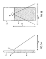
- FIGURES 3A and 3B illustrate side and front views, respectively, of a field of view of a video imaging device 60 in an automatic sliding door 62 according to a preferred embodiment of this invention.
- the field of view has a forward vision distance 64 and a vision width 66.
- the viewing direction of the video imaging device 60 is adjustable at the time of installation and maintenance. More preferably, the direction of view of the video imaging device 60 is adjustable with three axes of rotation at the time of installation and maintenance.
- one video imaging device 60 may be sufficient to both open the sliding door 62 and maintain the sliding door 62 in an open position while a person passes through the portal, if people approach from only one direction.
- LTC0330, LTC0350, TC590, LTC0500 LTC0330, LTC0350, TC590, LTC0500. It should be understood, however, that the present invention contemplates using any kind of imaging device or camera and should not be limited to these examples of commercially available ones.
- FIGURES 3A and 3B illustrate side and front views, respectively, of a field of view of a video imaging device 60 in an automatic sliding door 62 according to a preferred embodiment of this invention.
- the field of view has a forward vision distance 64 and a vision width 66.
- the viewing direction of the video imaging device 60 is adjustable at the time of installation and maintenance. More preferably, the direction of view of the video imaging device 60 is adjustable with three axes of rotation at the time of installation and maintenance.
- one video imaging device 60 may be sufficient to both open the sliding door 62 and maintain the sliding door 62 in an open position while a person passes through the portal, if people approach from only one direction. More typically, people will approach the automatic door illustrated in FIGURES 3A and 3B from both directions.
- a second video imaging device 70 is attached to an opposing side of the wall 72 compared to the video imaging device 60.
- FIGURES 3A and 3B illustrate a single sliding door 62, typically two video imaging devices per each side being monitored may be needed to provide adequate coverage for the approach area on one side of the wall in the case of wide double sliding doors. In the case of the sliding doors, all of the video imaging devices, such as video imaging devices 60 and 70 would provide both approach detection and threshold protection to maintain the sliding doors open while a person is still within the doorway.
Landscapes
- Engineering & Computer Science (AREA)
- Multimedia (AREA)
- Signal Processing (AREA)
- Power-Operated Mechanisms For Wings (AREA)
- Emergency Alarm Devices (AREA)
- Closed-Circuit Television Systems (AREA)
Abstract
Description
- The present invention relates to an automatic door assembly for controlling access through a door opening. More particularly, the present invention relates to an automatic door assembly that incorporates the use of a video imaging device that detects the approach of persons and objects to the door assembly and responsively signals the operator of the door assembly to open the door panel(s) thereof.
- In commercial and industrial buildings, such as, for example, retail stores, factories, warehouses, etc., it is often desirable to provide a video surveillance system to monitor persons and events within the building. One of the key areas where it is desired to direct such video surveillance is at the doorways that permit entrance and exit to certain areas. This allows security personnel to monitor the comings and goings of individuals through the doorways.
- In many commercial and industrial settings, there exists one or more doorways within a building provided with an automatic door assembly that automatically opens when a person approaches the doorway to permit entrance/exit therethrough. These automatic door assemblies typically use microwave doppler or active and passive infrared (IR) sensors to detect the motion of a person approaching the door. Also, some automatic door assemblies use pressure sensitive mats or electric eyes to determine the presence of a person in front of the door panel(s) thereof. Irrespective of which kind of sensor is used, when a sensor determines that a person is approaching the doorway, the controller of the door assembly responsively signals a door operator thereof to move the door panel(s) to the open position thereof to permit passage therethrough.
- In arrangements wherein a video surveillance device is being used to monitor a doorway in which an automatic door assembly is installed, the surveillance imaging device is mounted at a vantage point that provides a view of the persons travelling through the doorway while, at the same time, sensors on the door assembly are also monitoring the areas adjacent to or within the doorway to detect the presence of motion indicative of persons travelling through the doorway. Thus, the building owner is paying for the costs of two systems that function to some extent to monitor a doorway. Also, the imaging device that monitors the doorway and the door assembly itself are typically installed by different companies, thereby increasing installation costs.
- In US-A-6,084,367 (Landert) there is disclosed a door operating system having a variable programmed operating method to satisfy certain preselected criteria. It is said that a primary purpose of the system is to improve on a door system and a method of operating a door system such that the opening and closing of the door system are controlled individually as a function of the detected traffic situation' and as a function of ambient conditions. The door system can be programmed individually for a given building in such a way as to offer access or passage for people and/or vehicles with as little draught as possible on the one hand, while on the other hand presenting the least possible hindrance to such access or passage and also adapting precisely to the prevailing needs of the building at all times. One or more video cameras are connected to an appropriate video image processing system to ascertain how many people and/or vehicles are approaching the door system. In addition to detecting the traffic situation in front of the door system by means of video cameras, other detection media may also be provided such as weight identification or speed detection.
- US-A-6,084,367 discloses an automatic door assembly for installation at a doorway formed through a wall of a building, said door assembly comprising: a frame assembly constructed and arranged to be mounted to the building wall at the doorway thereof; a door panel constructed and arranged to be mounted to said frame assembly for movement between a closed position wherein said door panel is positioned in covering relation over the doorway to prevent persons and objects from travelling therethrough and an open position wherein said door panel is moved out of said covering relation to permit persons and objects to travel through the doorway; a door controlling system comprising: (i) a video imaging device constructed and arranged to be mounted in a viewing position wherein said imaging device monitors a field of view that encompasses at least an approach area located adjacent to the doorway, said video imaging device being adapted to transmit an internal video data signal comprising information representative of said field of view; and (ii) a detection system comprising a video signal processor that communicates with said video imaging device, said video signal processor being adapted to receive said internal video data signal from said imaging device and to process the information comprising said internal video data signal to determine whether a person or object has entered said approach area, said detection system being adapted to responsively transmit a door opening signal in response to said processor thereof determining that a person or object has entered said approach area; and a door operator constructed and arranged to be connected to said door panel and adapted to communicate with said detection system, said door operator being constructed and arranged to move said door panel from said closed position thereof to said open position thereof responsive to receiving said door opening signal.
- In accordance with the present invention in one aspect there is provided such an automatic door assembly, characterised in that said door controlling system is adapted to transmit an external video data signal comprising information representative of the field of view of said imaging device to a video processing device that is capable of (a) receiving the video data signal and (b) processing the video data signal into a form suitable for displaying images that are visually representative of the imaging device's field of view, thereby enabling said door controlling system to be in communication with the aforesaid video processing device so that the video device can process the external video data signal into a form suitable for displaying images that are visually representative of the field of view of said video imaging device including at least the approach area adjacent said doorway.
- There may also be provided in accordance with the present invention in another aspect a method of operating a doorway apparatus, said doorway apparatus comprising an automatic door assembly comprising: a frame assembly; a door panel mounted to the frame assembly for movement between a closed position, and an open position; a door controlling system comprising a video imaging device mounted in a viewing position to monitor a field of view that encompasses at least an approach area located adjacent to the automatic door assembly, and a detection system comprising a video signal processor in communication with the video imaging device; and a door operator connected to the door panel and in communication with the detection system; the method comprising: monitoring the field of view encompassing at least the approach area by the video imaging device receiving images of the field of view; transmitting, from the video imaging device to the video signal processor, an internal video data signal comprising information representative of the images received by the video imaging device; processing the internal video data signal by the processor to determine whether a person or object has entered the approach area; in response to the processor determining that a person or object has entered the approach area, transmitting a door opening signal to the door operator and; in response to receiving the door opening signal, moving the door panel from the closed position thereof to the open position thereof by the door operator; characterised by the additional steps of: transmitting, from the door controlling system to a remote video processing device, an external video data signal comprising information representative of the images received by the video imaging device and, operating the remote video processing device to process the external video data signal into a form suitable for displaying images that are visually representative of the images received by the video imaging device.
- There exists a need in the art for an arrangement wherein video imaging capabilities and sensing capabilities that determine the presence or approach of a person to a doorway controlled by an automatic door assembly are combined into one convenient package that can be easily installed to provide effective door assembly operation and video imaging functions.
- There will now be described a number of further features which may be provided in accordance with the present invention.
- In some arrangements the video imaging device is a digital video imaging device.
- The door controlling system may further comprise a door controller in communication with both said signal processor and said door operator and said video signal processor may be adapted to generate a detection signal and transmit the detection signal to the controller in response to determining that a person or object has entered the approach area; said door controller being adapted to generate and transmit said door opening signal to said operator in response to receiving said detection signal; said controller being adapted to (a) monitor the positioning of said door panel between said open and closed positions thereof and (b) select a speed at which said operator moves said door panel based on the said positioning of said door panel and in response to control said operator to move said door panel at said selected speed by varying an amplitude or frequency of said door operating signal.
- It may be arranged that the processor determines whether a person or object has entered the approach area by detecting motion of the person or object within the approach area.
- The said door panel may be a single sliding door panel movable generally rectilinearly within a threshold area of the doorway, or the door panel may be one of a pair of sliding door panels movable generally rectilinearly towards and away from one another within a threshold area of the doorway.
- In accordance with another aspect of the present invention there may be provided a combination comprising: a building having a wall with a doorway formed therethrough; an automatic door assembly generally as set out above with the frame assembly mounted to the building wall at the doorway thereof, and a video processing device as set out above communicated to the said door assembly's controlling system.
- In some arrangements the video processing device may be a video data storing device that (a) processes and stores the information comprising the external video data signal and (b) enables the stored information to be subsequently retrieved for displaying images that are representative of the field of view of said video imaging device including at least the approach area adjacent said doorway.
- In some arrangements said video processing device is a video display device that processes the information comprising the external video data signal and displays images that are visually representative of the field of said video imaging device including at least the approach area adjacent said doorway.
- Preferably, the imaging device is provided by a digital or analog video camera. The detection system may comprise both the processor and a standard door controller. The door controller would be of the type known in the art that is capable of monitoring the position of the door panel structure via a feedback mechanism and varying the amplitude or frequency of the door opening signal to control the speed at which the door operator opens the door panel(s). For example, it is usually desired to move the door panel relatively slowly at or near the fully opened and closed positions thereof and relatively faster in the middle of its travel path. In this arrangement, the processor generates a detection signal and transmits the same to the controller. Then the controller responsively generates and transmits the appropriate door opening signal to the operator based on the position of the door panel. In fact, if the door panel is already in the fully open position thereof, the controller may ignore the detection signal and not transmit any door opening signal to save on wear and tear of the operator. Alternatively, the functions of the controller may be built into the processor.
- The video device may include a video display device such as a video monitor or a video data storing device that stores the information for later retrieval and review in conjunction with a video display monitor.
- The terms internal and external are used with respect to the video data signals to emphasize the fact that the internal signal remains internal to the door assembly and is used by the door controlling system while the external system is output externally of the door assembly to the video device. As a result, the door assembly of the present invention provides the functions and advantages of a video imaging device and the door controlling functions of a typical door assembly into one convenient package. This convenience can be greatly appreciated by establishments that monitor their doorways with video surveillance because the provision of the video imaging device on the door assembly eliminates the need for separately purchasing and installing a video imaging device for monitoring the doorway.
- In prior art arrangements, such as those disclosed in U.S. Patent Nos. 4,914,859 and 4,565,029, a number of individual energy emitters and detectors are provided in the assembly to provide coverage for the travel area of the door panel structure. The '859 patent relates to a sliding door assembly and the '029 patent relates to a swing door assembly. Each of these assemblies uses a position sensor to determine the position of the door panel structure between the open and closed positions thereof. In each of these assemblies, the processor selectively activates and deactivates the individual detectors as needed to ensure that movements of the door panel structure do not trigger the detectors and responsively cause generation of a door opening signal. These designs, however, are expensive because of the costs associated with obtaining and installing multiple individual detectors, and the increased design costs associated with integrating each of the detectors into the overall system design. Also, the use of multiple detectors introduces additional points for malfunctions.
- To obviate the problems with these prior art arrangements discussed above, in another aspect of the invention the door controlling system comprises a video imaging device constructed and arranged to be mounted in a viewing position wherein the imaging device monitors a field of view that encompasses at least a door panel travel area through which the door panel moves during movement thereof between the open and closed positions. The door controlling system also comprises a detection system comprising a video signal processor that communicates with the video imaging device. The video signal processor is adapted to receive the video data signal from the imaging device and to process the information comprising the internal video data signal to determine whether a person or object is in the door panel structure travel area. The detection system is adapted such that the processor ignores the movement of the door panel within the door panel travel area so that the door panel is not determined by the processor to be a person or object in the predetermined area. The detection system is also adapted to responsively transmit a door opening signal in response to the processor thereof determining that a person or object is within the door panel travel area. A door operator is constructed and arranged to be connected to the door panel and adapted to communicate with the detection system. The door operator is constructed and arranged to move the door panel from the closed position thereof to the open position thereof through the door panel travel area responsive to receiving the door opening signal.
- The assembly of this aspect of the invention is advantageous because the travel area of the door panel can be properly monitored by an imaging device without the costs and complexities associated with continually activating and deactivating multiple sensors as in the prior art arrangements.
- Other objects, features, and advantages of the present invention will become apparent from the following detailed description, the accompanying drawings, and the appended claims.
- Embodiments of the invention will now be describd by way of example with reference to the accompanying drawings, in which:-
- Figure 1 is a perspective view of a sliding door assembly installed in a wall of a building, the door assembly having a video camera provided thereon in accordance with an embodiment of the present invention;
- Figure 2 is a schematic illustration of the components that communicate with the video camera provided on the door assembly;
- Figures 3A and 3B are schematic illustrations showing the placement and orientation of video imaging devices according to a preferred embodiment of the invention;
- Figure 4 is a schematic illustration of components of a feedback mechanism for door positions and motion; and
- Figure 5 illustrates the general features of signals output from the feedback mechanism of Figure 4.
-
- Figure 1 is a perspective view of a sliding door assembly embodying the present invention, generally indicated at 100, mounted within a
doorway 102 of awall 104 of abuilding 106, the remainder of the building being cut-away around thedoorway 102. Thedoor assembly 100 comprises a frame assembly, generally indicated at 108, that mounts within thedoorway 102. Theframe assembly 102 comprises aheader 110 that houses the door operator (shown schematically at 16 in Fig. 2) and the door controlling system (shown schematically at 10 in Fig. 2) that controls thedoor operator 16, whichsystem 10 will be described in more detail hereinbelow. Theframe assembly 108 also comprises a pair ofnon-sliding panels 112 that cover opposing sides of thedoorway 102. - The
door assembly 100 further comprises door panel structure in the form of a pair of slidingdoor panels door panels doorway 102 that are not covered by thenon-sliding panels 112 to prevent the travel of persons and objects therethrough. In the open position thereof, thedoor panels doorway 102 to permit the travel of persons and objects through thedoorway 102. - The
door operator 16 may be of any known construction, such as hydraulic or electromechanical, and connects to door panel carriers (not shown) that are housed inside theheader 110. Each of thedoor panels header 110 toward or away from one another to provide thedoor panels door operator 16 operates to move the door panel carriers away and towards one another to effect the movement of thedoor panels - In accordance with this embodiment of the present invention the
door assembly 100 also comprises a video imaging device (shown schematically at 26 in Fig. 2) housed within avideo camera 120 that is mounted in a viewing position to the outwardly facing surface of theheader 110. In this viewing position, theimaging device 26 of thecamera 120 has a field of view as demarcated bylines 122 that encompasses anapproach area 124 disposed adjacent to thedoorway 102. This enables theimaging device 26 to monitorapproach area 124. It is contemplated that the imaging device's field of view may also encompass thedoorway 102 itself (i.e., the threshold area). This enables thedevice 26 to monitor both theapproach area 124 for persons approaching the doorway and the threshold area within thedoorway 102 itself for persons stopped and standing therein. The role and function of theimaging device 26 is explained in further detail hereinbelow. - Figure 2 schematically illustrates the general concepts and arrangement of the present embodiment of the invention. The door controlling system, generally indicated at 10, is housed within the header 110 (Fig. 1) and communicates with the door operator, which is indicated schematically in this Fig. 2 at 16. The
door controlling system 10 has one or more video imaging units, each indicated at 26 and housed withinvideo cameras 120 similar tovideo camera 120 shown in Fig. 1. Thedoor controlling system 10 also comprises amotion detection sub-system 31. Thissub-system 31 comprises one or morevideo camera processor 32 and a door controller 14 that communicates with theoperator 16. Each of thecameras 120 houses one of saidprocessors 32 that is adapted to generate a motion detection signal and transmit the signal to the controller 14 in a manner that is described in further detail hereinbelow. The door controller 14 is adapted to generate a door opening signal and transmit the signal to theoperator 16 in a manner that is described in further detail hereinbelow. - In the arrangement illustrated in Fig. 2, there are a plurality of said
video cameras 120. Each of thecameras 120 has an electronicvideo imaging device 26, preferably in the form of a digital video imaging device. - For the sake of simplicity, the manner in which the door controlling system operates will be described under the assumption that only one
camera 120, and thus only onevideo imaging device 26 and oneprocessor 32, is being used. Thesignal processor 32 receives and processes video data from thevideo imaging device 26. More specifically, thevideo imaging device 26 generates and transmits an internal video data signal comprising information representative of its field of view. This internal video data signal is received by theprocessor 32 and processed or evaluated to determine whether a person or object has entered into the approach area. The specific way in which theprocessor 32 makes this determination will be described in further detail below. When theprocessor 32 determines that a person or object has entered theapproach area 24, theprocessor 32 generates and transmits a motion detection signal to the controller 14, which in turn transmits a door opening signal to the door operator 16 (assuming .thedoor panels - The controller 14 may be of any type known in the art. Such a controller 14 would treat the motion detection signal from the
processor 32 in the same manner as it would if it were a motion detection signal that was transmitted from other well known motion or presence detection systems, such as IR or microwave doppler sensors. As is well-known in the art, the controller 14 monitors the position of the door and uses that information to vary the amplitude or frequency of the door opening signal to affect faster or slower movement of the door panel(s). For example, it is usually desirable that thedoor operator 16 moves the door panel(s) slower at or near the fully opened and closed positions thereof. The controller 14 monitors the position of the door panel(s) using the same well-known Hall effect sensor arrangement that is described hereinbelow. The controller 14 may also be adapted to wait a predetermined period of time after the processor has ceased generating and transmitting the motion detection signal and then generate and transmit a door closing signal to theoperator 16. - Alternatively, the use of a separate controller and a separate processor may be obviated by using a single processor that performs the above-described functions of both the
processor 32 and the controller 14. - To determine whether an object or person has entered the approach area monitored by the
video imaging device 26, theprocessor 32 processes or evaluates the information comprising the internal video data signal in accordance with known algorithms in order to detect movement of a person or object in or into the imaging device's the field of view. For example, an image frame taken at one time may be stored and compared with a subsequent image frame taken at a later time. In the case of a digital image, a pixel-by-pixel comparison may be performed between the two images. In that case, if a pixel has a different image value in the subsequent image than in the earlier image, a change in pixel value is tallied for that pixel. If a large object, such as a person, moves between the time of the earlier image, and the subsequent image, then a large number of pixels will register as having different values between the two images. - To distinguish between small pixel changes due to noise, which is almost always present at some level, a detection threshold value is set. When the number of pixels registering as having different values exceeds the set detection threshold value, the
processor 32 responsively treats that as motion and transmits the motion detection signal to the controller 14. The detection threshold value can be set at a higher value to eliminate detection of small objects, such as paper blown through the field of view by the wind or other such debris, or small animals such as insects, small birds, and squirrels that may move through the field of view. Preferably, the detection threshold value is set to a value at which motion of a small child is detected. Preferably, motion of a 70cm (= 28 inch) tall child that is approximately 25 cm (=10 inch) wide and approximately 15 cm (= 6 inch) deep and moving at between 8.1 cm (3.2 inches) per second to feet 76.2 cm (= 2.5 feet) per second is detected. In addition, the detection threshold may be set such that partially solid objects such as wire frame or. plastic shopping carts are detected. - In another embodiment of the invention, the
processor 32 filters out the background image and distinguishes certain moving objects from a person or people approaching the automatic door. In the case of background filtering, background objects will typically be stationary on a time scale which is long compared to the time it takes for a person to walk into the view of a video imaging device, and to pass through the automatic door and travel out of the field of view of the opposing video imaging device. For example, blowing paper or leaves may blow into the field of view, and then remain steady for many minutes, hours or even days. Objects may be rearranged and moved, for example, relocating a trashcan within the field of view. Changing weather conditions, such as snow, may present relatively fixed background images. - In an arrangement wherein a plurality of
imaging devices 26 are used, such as the arrangement in Figure 2, each of theimaging devices 26 generates and transmits an internal video data signal to its associatedprocessor 32. Eachprocessor 32 processes or evaluates its respective signal to determine whether a person or object has entered into any of the areas monitored by theimaging devices 26. When one of theseprocessors 32 determines that a person or object has entered one of these monitoredareas 24, thatprocessor 32 generates and transmits a motion detection signal to the controller 14, which in turn transmits a door opening signal to the door operator 16 (assuming thedoor panels - In the preferred embodiment, a black-and-white digital camera that employs CCD elements for image pickup is used to provide the video imaging device(s) 26. Color video imaging devices may be used in other embodiments. Furthermore, embodiments of the invention are not limited to only digital imaging devices. Analog video cameras may be used in other embodiments of the invention.
- A
camera 120 may includeLED indicators 28 that provide information on the operational status of a master camera and its imaging device during the installation, operation and/or maintenance thereof. - The camera(s) 120 are selectively attached to portions of an automatic door assembly and/or structures immediately adjacent thereto. The number of
cameras 120 used and their particular placement will depend on the particular type of automatic door assembly and, in some cases, on the size of the door. The most common applications may be categorized as sliding doors, swinging doors, and bi-fold doors. In the case of swing doors, there are four common types of swing doors encountered: uni-directional single door, uni-directional double door, bi-directional single door, and bi-directional double door. - The video imaging device(s) 26 of the door controlling system are also communicated to a remotely located external video device that is capable of processing a video data signal received from a
video imaging device 26 into a form that is suitable for displaying images that are visually representative of the imaging device's field of view. In the arrangement wherein more than oneimaging device 26 is provided in thedoor controlling system 10, it may be that only the video data signal from oneimaging device 26 will be transmitted as the external video data signal to the external video device; although it may be desirable to transmit external video data signals from two or more of theimaging devices 26 of one controllingsystem 10 that have significantly different fields of view. Alternatively, the external video signals from a plurality ofimaging devices 26 may be transmitted to a single video device for simultaneous viewing or storage and subsequent viewing with the fields of view being shown in "split screen" fashion. This external video data signal may be transmitted to the external video device directly from theimaging device 26 that generates it in parallel with the processor or it may be transmitted to the external video device indirectly through thevideo processor 32 in series therewith. Like the internal video data signal (which may be digital or analog), the external video data signal (which may be digital or analog) comprises information that is visually representative of the imaging device's field of view. - The external video device may be a video data storing device, shown at 18, that is capable of processing a video data signal and storing the same for later use in conjunction with a display device, thereby allowing events taking place in the camera's field of view to be reviewed at a later time. The video
data storing device 18 is preferably a high-capacity unit, but may generally be selected from a wide range of available semiconductor storage devices, magnetic storage devices, or optical storage media, such as flash memories, hard drives, removable magnetic media, recordable CD, recordable DVD disks, or standard VHS VCR tape, for example. - A further preferred feature of the video
data storing device 18 is that it is adapted to record only when motion is detected in the field of view of theimaging device 26 from which the external video data signal is derived. To accomplish this, it may be arranged that eachprocessor 32 is in communication with the activating device of the storingdevice 18 and transmits the same motion detection signal that it transmits to the controller 14. Alternatively, the controller 14 may be in communication with the activating device of the storingdevice 18 so that the controller 14 activates thestorage device 18 responsive to receiving the motion detection signal from one of the processors. The storingdevice 18 normally stays inactive and does not record or otherwise store the external video signal transmitted thereto. However, when the activating device thereof receives the motion detection signal, or a corresponding signal from the controller 14 activates thevideo storing device 18, which in turn begins recording or storing the external video data signal. For further details concerning this feature, reference may be made to U.S. Patent Nos. 5,602,585 and 5,880,775. - Alternatively, the external video device may be a video display device in the form of one or more video monitors, shown at 20. The
monitor 20 may be viewed by security personnel to track the travel of persons and objects through thedoorway 102. In a future application, themonitor 20 may be located at a remote service location and be in communication with thedoor controlling system 10 via a digital or analog network. This could enable a service or repair technician to visually verify the operational condition of the door assembly (assuming an imaging device on the door assembly has pertinent portions such as the door panel(s) within its field of view) prior to travelling to the location of thedoor assembly 100. This can reduce the need for travelling of the repair technician to handle problems that he could easily instruct on-site persons to handle over the telephone while viewing their activities on themonitor 20. - In a preferred embodiment of the invention the
processor 32 distinguishes between particular "known" moving objects and other moving objects. In particular, theprocessor 32 recognizes detection of the moving door panel(s) themselves and ignores such movement. That is, theprocessor 32 detects the motion of a door panel within a field of view of an imaging device, but does not generate a motion detecting signal in response to such motion. - One exemplary way to accomplish this is to generate a look-up table of data. However, the invention also anticipates using algorithms to recognize known moving objects instead of, or in addition to, look-up tables of data. In generating a look-up table, a table of motion data corresponding to a motion map for the moving door panel(s) is generated in correlation with known motion and positions of the door panel(s). Preferably, sensors are placed on components, which move in correlation with the motion of the door. A suitable feedback mechanism that may be used is disclosed in U.S. Patent No. 4,565,029.
- The feed back mechanism may also have two Hall effect transistors positioned on a circuit board that is fastened to the rear of the motor housing used to effect opening and closing of the door. The motor shaft protrudes through the rear of the motor housing where a small magnetically-charged disk having four poles spaced 90° from one another is fastened to the motor shaft. As the motor rotates, the magnetic disk rotates causing four magnetic fields, each created by one of the poles and alternating between positive and negative, to pass alongside the two Hall effect transistors. The transistors are positioned substantially along a circular arc relative to the axis of rotation 22½° out-of-phase from each other. A power source is connected to the transistors, and the transistors act as switches that close momentarily each time a magnetic pole passes alongside the two transistors. This results in two separate periodic waveforms from the transistor-magnetic field configuration, each of which is generated by a respective one of the sensors. The two waveforms are substantially identical squarewaves having two values that may be referred to a high and low and are 22½° out-of-phase with each other due to the relative positioning of the transistors along the path of rotation.
- The two waveforms are transmitted to the
processor 32 either directly or indirectly via the controller 14. The two waveforms output from the feedback mechanism are utilized by the processor to determine the position, direction, and speed of the moving door. Generally, the position and direction of motion of the door are of greater interest than the speed of the door. - FIGURE 4 is a schematic drawing illustrating an example of such a feedback mechanism. It should be understood that this arrangement is only provided as an illustrative example and is not intended to be limiting. The motor has a
motor housing 74 and arotating shaft 76 protruding through the rear of themotor housing 74. TwoHall effect transistors motor shaft 76. A magnetic disk on themotor shaft 76 creates a periodic magnetic field, which actuates theHall effect transistors positive pole Hall effect transistor 78, 82 it causes the signal of that transistor to switch from a low state to a high state. Likewise, when eachnegative pole transistor motor shaft 76 rotates through successive revolutions. - The output signal created by this action is illustrated in FIGURE 5 at 84. FIGURE 5 also illustrates the
signal 86 output from theHall effect transistor 80, which it should be noted is 22½° out of phase withsignal 84. For the time axis going from left to right in FIGURE 5, thesignal output 86 fromHall effect 80 transistor remains low for a 22½° turn of theshaft 76 after theoutput signal 84 from theHall effect transistor 78 is switched to a high value. After the 22½° rotation of themotor shaft 76, thepositive pole 82A is then proximate theHall effect transistor 80 thus causing thesignal 86 to switch from a low value to a high value. Thesignal 86 remains at a high value for another 90° turn of themotor shaft 76 untilnegative pole 82B isproximate transistor 80. However, before that occurs. after 67½° thenegative pole 82B passes proximate to theHall effect transistor 78, and thus it switches thesignal 84 thereof to a low value while thesignal 86 from theHall effect transistor 80 remains at a high value. - One may think of each value of the
squarewaves motor shaft 76. Thus, thesignal 86 lags thesignal 84 by 22½° for rotations of themotor shaft 76 in the counterclockwise direction such that eachsuccessive pole 82A, B, C, D rotates from theHall effect transistor 78 counterclockwise to theHall effect transistor 80. In other words, each transition from a high value to a low value or a low value to a high value of thesignal 84 occurs in one of the above-mentioned units prior to a transition of thesignal 86 from a low value to a high value or a high value to a low value. - In the case where the
motor shaft 76 rotates in the clockwise direction, the signal from theHall effect transistor 80 is represented in FIGURE 5 bysignal 88. In this case, transitions from a high value to a low value or a low value to a high value of thesignal 88 lags corresponding transitions of thesignal 84 by 22½° because eachpole 82A, B, C, D passesproximate transistor 80 prior totransistor 78. Consequently, the asymmetry and the positioning of theHall effect transistors Hall effect transistor 78 relative toHall effect transistor 80. Although theHall effect transistors - In operation, as the door moves the two waveforms from the
Hall effect transistors processor 32 evaluates both waveforms simultaneously. In FIGURE 5, signal 84 is initially in ahigh state 90 while thesignal 86 is in thelow state 91. As the door moves in a particular direction, for example, forward or open, corresponding to counterclockwise rotation ofmotor shaft 76, thewaveform 84 atstate 93 remains at a high value while for asignal 86, it transitions for ahigh value 94. Theprocessor 32 comparessignals portions portions - As the door continues to move, the controller will process additional state transitions, such as comparing
portions 94 to 95 and 96 to 98, corresponding to low-high values and low-low values. This process is continued for succeeding transitions. Theprocessor 32 recognizes any transition of states of door motion. In the preferred embodiment, there are two separate algorithms to determine the actual door position, and the direction of travel. - In regard to the door position, when the door assembly is initially powered up, the door panel moves very slowly to the full open position which is defined as the zero position. As the door starts to close, the two
output waveforms processors 32 in the arrangement with more than one camera 120). Theprocessor 32 logs each transition of eithersignal processor 32 also evaluates the state changes to determine the type of state change. A high-low state is always followed by a high-high state in the door opening direction, and a high-high state is always followed by a low-high state in the same door opening direction. Conversely, a high-low state is always followed by a low-low state in the door closing direction, and this low-low state is then followed by a low-high state in the door closing direction. These state change differences may be reversed. Thus, when a state change is detected and the processor determines that it is a state change that corresponds to movement in the door opening direction, the processor increases the position number by 1. Conversely, when a state change is detected and the processor determines that it is a state change that corresponds to movement in the door closing direction, the processor decreases the position number by 1. As a result, because the processor continually evaluates these feedback signals 84 and 86 for both distance and direction of travel, the processor always "knows" the position of the door panel as defined by its position number. - The number of positions will vary depending on the type of door set up, size of motor and gearbox configuration, etc. For a 90° swing door, there are approximately 640 positions between full open and full closed which translates to roughly 7 positions per degree of door travel. For sliding doors, there are roughly 14 positions per inch of travel. This again depends on the motor/gearbox configuration and the timing belt pulley circumference and other mechanical components.
- In order for the automatic door to recognize detected motion of the door as being distinguishable from the motion of a person, the video sensor system performs what may be viewed as a learn mode. During the initial power-up cycle of the door system, the door position and travel direction is established and monitored. In addition to this, the processor 32 (or
processors 32 in the arrangement with more than one camera 120) also goes through a learn phase. During the learn phase, care is taken to ensure that other moving objects do not corrupt the data taken during the learn phase. The door is moved from the full open position to the full closed position. While this occurs, the video sensor system logs the door position number in memory along with information demarcating the area within the camera's field of view in which the door panel is located and moving. The process continues for each and every door position. This generates a look up table that has a information concerning the location of the door panel with the imaging device's field of view for each and every position of the door panel. - During operation of the door assembly, as the processor evaluates the internal video data signal from a video imaging device, it looks to the look up table generated during the learn mode. By looking at the look up table, the processor 32 (or processors 32) determines the area where the door panel is in the imaging device's field of view and ignores motion in that area. The area of door motion is said to be masked so that during normal door operation the masked area will be insensitive to motion for as long as the door panel is in the specific position stored in a look-up table accessed by the controller. As the door moves to another position, the masked area is removed so that the same area will then be sensitive to motion occurring within the previously masked area. After the door has moved, there is then a new masked area associated with the new door position, which is again insensitive to motion.
- Although the above described masked areas as being sensitive and insensitive to motion, other embodiments include recognizing the appearance of new objects in addition to moving objects. For example, a person who is motionless within the swing path of a swinging door or within the slide path of the sliding door will be recognized in this embodiment as being different from the pre-established background image. Again, during the learn mode of the processor 32 (or processors 32), the field of view is learned in the sense that background images are stored in a look-up table, thus permitting later comparison to determine significant changes to the background image during normal door operation. This is often referred to as "presence" sensing.
- In addition to a learn mode to learn motion and/or video image of a door, one may perform a learn mode to generate a look-up table, or otherwise provide an algorithm, such that other objects besides the door panels can be ignored. For example, in an automatic door which has imaging devices having a view of moving vehicle traffic can generate a look-up table in a learn mode in order to ignore the moving vehicle traffic.
- The above describes features of preferred embodiments of this invention which may be combined with conventional door actuators and door controllers to provide visual sensors and surveillance. Video detection, recording and processing equipment is commercially available. For example, the SILENT WITNESS® video surveillance systems provide video motion detection and tracking capability which may be programmed and integrated into the video sensor and surveillance system according to the instant invention.
- Also, one could use cameras similar to those available from Philips Electronics, such as Model Nos. VC7A775T, VC7A795T, LTC0140, LTC0330, LTC0350, TC590, LTC0500. It should be understood, however, that the present invention contemplates using any kind of imaging device or camera and should not be limited to these examples of commercially available ones.
- FIGURES 3A and 3B illustrate side and front views, respectively, of a field of view of a
video imaging device 60 in an automatic slidingdoor 62 according to a preferred embodiment of this invention. The field of view has aforward vision distance 64 and avision width 66. Preferably, the viewing direction of thevideo imaging device 60 is adjustable at the time of installation and maintenance. More preferably, the direction of view of thevideo imaging device 60 is adjustable with three axes of rotation at the time of installation and maintenance. - In the case of a single sliding door, as illustrated in FIGURES 3A and 3B, one
video imaging device 60 may be sufficient to both open the slidingdoor 62 and maintain the slidingdoor 62 in an open position while a person passes through the portal, if people approach from only one direction. LTC0330, LTC0350, TC590, LTC0500. It should be understood, however, that the present invention contemplates using any kind of imaging device or camera and should not be limited to these examples of commercially available ones. - FIGURES 3A and 3B illustrate side and front views, respectively, of a field of view of a
video imaging device 60 in an automatic slidingdoor 62 according to a preferred embodiment of this invention. The field of view has aforward vision distance 64 and avision width 66. Preferably, the viewing direction of thevideo imaging device 60 is adjustable at the time of installation and maintenance. More preferably, the direction of view of thevideo imaging device 60 is adjustable with three axes of rotation at the time of installation and maintenance. - In the case of a single sliding door, as illustrated in FIGURES 3A and 3B, one
video imaging device 60 may be sufficient to both open the slidingdoor 62 and maintain the slidingdoor 62 in an open position while a person passes through the portal, if people approach from only one direction. More typically, people will approach the automatic door illustrated in FIGURES 3A and 3B from both directions. To detect people approaching from both directions, a secondvideo imaging device 70 is attached to an opposing side of thewall 72 compared to thevideo imaging device 60. Although FIGURES 3A and 3B illustrate a single slidingdoor 62, typically two video imaging devices per each side being monitored may be needed to provide adequate coverage for the approach area on one side of the wall in the case of wide double sliding doors. In the case of the sliding doors, all of the video imaging devices, such asvideo imaging devices
Claims (31)
- An automatic door assembly for installation at a doorway (102) formed through a wall (104) of a building (106), said door assembly comprising:characterised in that said door controlling system (10) is adapted to transmit an external video data signal comprising information representative of the field of view of said imaging device (26, 60) to a video processing device that is capable of (a) receiving the video data signal and (b) processing the video data signal into a form suitable for displaying images that are visually representative of the imaging device's field of view, thereby enabling said door controlling system to be in communication with the aforesaid video processing device so that the video device can process the external video data signal into a form suitable for displaying images that are visually representative of the field of view of said video imaging device (26, 60) including at least the approach area adjacent said doorway.a frame assembly (108) constructed and arranged to be mounted to the building wall (104) at the doorway (102) thereof;a door panel (114, 116, 62) constructed and arranged to be mounted to said frame assembly (108) for movement between a closed position wherein said door panel is positioned in covering relation over the doorway to prevent persons and objects from travelling therethrough and an open position wherein said door panel is moved out of said covering relation to permit persons and objects to travel through the doorway;a door controlling system (10) comprising:(i) a video imaging device (26, 60) constructed and arranged to be mounted in a viewing position wherein said imaging device (26, 60) monitors a field of view that encompasses at least an approach area located adjacent to the doorway, said video imaging device (26, 60) being adapted to transmit an internal video data signal comprising information representative of said field of view; and(ii) a detection system comprising a video signal processor (32) that communicates with said video imaging device (26, 60), said video signal processor (32) being adapted to receive said internal video data signal from said imaging device (26, 60) and to process the information comprising said internal video data signal to determine whether a person or object has entered said approach area, said detection system being adapted to responsively transmit a door opening signal in response to said processor (32) thereof determining that a person or object has entered said approach area; anda door operator (16) constructed and arranged to be connected to said door panel (114, 116, 62) and adapted to communicate with said detection system, said door operator (16) being constructed and arranged to move said door panel (114, 116, 62) from said closed position thereof to said open position thereof responsive to receiving said door opening signal;
- An automatic door assembly according to claim 1, wherein said video imaging device (26, 60) is a digital video imagining device.
- An automatic door assembly according to claim 1 or 2, wherein said door controlling system (10) further comprises a door controller (14) in communication with both said signal processor (32) and said door operator (16) and wherein said video signal processor (32) is adapted to generate a detection signal and transmit said detection signal to said controller (14) in response to determining that a person or object has entered said approach area;
said door controller (14) being adapted to generate and transmit said door opening signal to said operator (16) in response to receiving said detection signal;
said controller (14) being adapted to (a) monitor the positioning of said door panel (114, 116, 62) between said open and closed positions thereof and (b) select a speed at which said operator (16) moves said door panel based on the said positioning of said door panel and in response to control said operator (16) to move said door panel at said selected speed by varying an amplitude or frequency of said door opening signal. - An automatic door assembly according to claim 1, 2 or 3, wherein said processor (32) determines whether a person or object has entered said approach area by detecting motion of the person or object within said approach area.
- An automatic door assembly according to any preceding claim, wherein said frame assembly (108) includes a header (110) and said video imaging device (26, 60) is housed within said header (110).
- An automatic door assembly according to any preceding claim, wherein said door panel is a single sliding door panel movable generally rectilinearly within a threshold area of said doorway.
- An automatic door assembly according to any of claims 1 to 5, wherein said door panel is one of a pair of sliding door panels (114, 116, 62) movable generally rectilinearly towards and away from one another within a threshold area of said doorway.
- A doorway apparatus comprising:an automatic door assembly (100) according to any preceding claim;
anda remotely located video processing device (18, 20) in communication with said door assembly's controlling system (10), said video processing device (18, 20) being adapted to receive said external video data signal and to process the external video data signal into a form suitable for displaying images that are visually representative of the field of view of said video imaging device (26, 60). - Apparatus according to claim 8, wherein said video processing device comprises a video data storing device (18) that (a) stores the information of the external video data signal and (b) enables the stored information to be subsequently retrieved for displaying images that are visually representative of the field of view of said video imaging device (26, 60) including at least the approach area adjacent said doorway.
- Apparatus according to claim 8 or 9, wherein said video processing device comprises a video display device (20) that processes the external video data signal and displays images that are visually representative of the field of view of said video imaging device (26, 60) including at least the approach area adjacent said doorway.
- An automatic door assembly according to any of Claims 1 to 7 wherein said imaging device (26, 60) monitors a field of view that encompasses at least a door panel travel area through which said door panel (114, 116, 62) moves during movement thereof between said open and closed positions, said video imaging device being operable to monitor the field of view by receiving images of the field of view and transmitting a video data signal comprising information representative of said images;
said detection system also comprising a memory including a plurality of stored images of the door travel area corresponding to a plurality of positions of the door panel (114, 116, 62) within the door travel area, ; and
said door operator (16) being constructed and arranged to move said door panel between the open and closed positions through said door panel travel area and to move the door panel towards said open position thereof in response to receiving a door opening signal; there being provided a position sensor in communication with said processor (32) for monitoring a position of the door panel within the door panel travel area;
the video signal processor (32) being adapted to determine whether a person or object other than the door panel is within the door panel travel area by comparing an image received via the video data signal against the stored image corresponding to the position of the door panel (114, 116, 62) as monitored by the position sensor, said detection system being adapted to transmit a door opening signal to the door operator in response to the processor determining that a person or object is within the door travel area. - An automatic door assembly according to claim 11, wherein said door panel travel area is a threshold area within said doorway (102) and wherein said door panel (114, 116, 62) is sliding door panel that moves generally rectilinearly within said threshold area in the doorway between said open and closed positions thereof.
- An automatic door assembly according to claim 11 or 12, wherein said field of view encompasses an approach area (124) located adjacent to and extending away from said doorway (102),
said video signal processor (32) being adapted to process said video data signal to determine whether a person or object is in said approach area (124), said detection system being adapted to responsively transmit said door opening signal in response to said processor (32) thereof determining that a person or object is within said approach area. - An automatic door assembly according to claim 11, 12 or 13, wherein said position sensor is a Hall effect sensor.
- An automatic door assembly according to any of claims 11 to 14, wherein said door controlling system (10) is adapted to transmit an external video data signal comprising information representative of the images received by said imaging device, thereby enabling the external video data signal to be transmitted to the aforesaid video device (18, 20) so that the video device can process the external video data signal into a form suitable for displaying images that are visually representative of the images received by the imaging device (26, 60).
- A doorway apparatus comprising:an automatic door assembly (100) according to any of Claims 1 to 7 wherein said video imaging device (26, 60) is operable to monitor the field of view by receiving images of the field of view and transmitting a video data signal comprising information representative of said images; anda video recorder (18) in communication with said door assembly's controlling system (10), said video recorder (18) being adapted to receive said video data signal and store the information of the video data signal for subsequent retrieval for displaying images that are visually representative of the images received by said video imaging device (26, 60).
- Apparatus according to Claim 16, wherein the video recorder (18) is located remotely from the automatic door assembly (100), and wherein the video data signal is transmitted externally of the automatic door assembly to the video recorder.
- Apparatus according to Claim 16 or 17, wherein the video recorder (18) stores the information of the video data signal only when a person or object has entered the approach area.
- Apparatus according to Claim 18, wherein the door controlling system (10) is adapted to transmit a signal to the video recorder (18) to activate the video recorder to store the information of the video data signal in response to the processor (32) determining that a person or object has entered the approach area.
- A method of operating a doorway apparatus, said doorway apparatus comprising an automatic door assembly (100) comprising: a frame assembly (108); a door panel (114, 116, 62) mounted to the frame assembly (108) for movement between a closed position, and an open position; a door controlling system (10) comprising a video imaging device (26, 60) mounted in a viewing position to monitor a field of view that encompasses at least an approach area (124) located adjacent to the automatic door assembly, and a detection system comprising a video signal processor (32) in communication with the video imaging device; and a door operator (16) connected to the door panel (114, 116, 62) and in communication with the detection system; the method comprising:monitoring the field of view encompassing at least the approach area (124) by the video imaging device (26, 60) receiving images of the field of view;transmitting, from the video imaging device (26, 60) to the video signal processor (32), an internal video data signal comprising information representative of the images received by the video imaging device (26, 60);processing the internal video data signal by the processor (32) to determine whether a person or object has entered the approach area;in response to the processor (32) determining that a person or object has entered the approach area, transmitting a door opening signal to the door operator (16) and;in response to receiving the door opening signal, moving the door panel (114, 116, 62) from the closed position thereof to the open position thereof by the door operator (16);
characterised by the additional steps of:transmitting, from the door controlling system (10) to a remote video processing device (18, 20), an external video data signal comprising information representative of the images received by the video imaging device (26, 60) and,operating the remote video processing device (18, 20) to process the external video data signal into a form suitable for displaying images that are visually representative of the images received by the video imaging device (26, 60). - A method according to claim 20, wherein the remote video processing device comprises a video data storing device (18) and the method includes storing the information of the external video data signal, and subsequently retrieving the stored information for displaying images that are visually representative of the images received by the video imaging device (26, 60).
- A method according to claim 20 or 21, wherein the remote video processing device comprises a video display device (20) and the method includes displaying images that are visually representative of the images received by the video imaging device.
- A method according to claim 20, 21 or 22, including determining by the processor (32) whether a person or object has entered the approach area by detecting motion of the person or object within the approach area.
- A method according to claim 20, 21, 22 or 23, wherein said door controlling system (10) further comprises a door controller (14) in communication with both the signal processor (32) and the door operator (16), the method including:transmitting by the processor (32) a detection signal to the door controller (14) in response to determining that a person or object has entered the approach area; andtransmitting by the door controller (14) the door opening signal to the door operator (16) in response to receiving the detection signal.
- A method according to any of Claims 20 to 24 for monitoring a door travel area associated with the automatic door assembly (100), said door panel (114, 116, 62) being mounted to the frame assembly (108) for movement in the door travel area between the closed position and the open position; wherein the imaging device (26, 60) monitors a field of view that encompasses at least the door travel area, the detection system (10) also comprises a memory including a plurality of stored images of the door travel area corresponding to a plurality of positions of the door panel (114, 116, 62) within the door panel travel area, and said automatic door assembly includes a position sensor in communication with the processor; the method comprising:monitoring the field of view encompassing at least the door travel area by the video imaging device (26, 60) receiving images of the field of view;transmitting, from the video imaging device (26, 60) to the video signal processor (32), a video data signal comprising information representative of the images received by the video imaging device;monitoring a position of the door panel (114, 116, 62) within the door travel area by the position sensor;determining whether a person or object other than the door panel (114, 116, 62) is within the door panel travel area by the processor (32) by comparing an image received via the video data signal against the stored image corresponding to the position of the door panel as monitored by the position sensor;in response to the processor determining that a person or object other than the door panel is within the door travel area, transmitting a door opening signal to the door operator (16); andin response to receiving the door opening signal, moving the door panel (114, 116, 62) towards the open position thereof.
- A method according to Claim 25, wherein the door panel travel area is a threshold area and wherein the door panel (114, 116, 62) is a sliding door panel that moves generally rectilinearly within the threshold area between the open and closed positions thereof.
- A method according to Claim 25 or 26, wherein the field of view encompasses an approach area (124) located adjacent to and extending away from the door assembly (100),
wherein the video signal processor (32) processes the video data signal to determine whether a person or object is in the approach area,
wherein the detection system transmits the door opening signal in response to the processor determining that a person or object is within the approach area. - A method according to any of Claims 20 to 27, the method including:in response to the processor determining that a person or object has entered the approach area, transmitting a door opening signal to the door operator (16);in response to receiving the door opening signal, moving the door panel (114, 116, 62) from the closed position thereof to the open position thereof by the door operator; andtransmitting the external video data signal from the door controlling system to a video recorder (18),the video recorder (18) storing the information of the video data signal for subsequent retrieval for displaying images that are visually representative of images received by the video imaging device (26, 60).
- A method according to Claim 28, wherein the video recorder (18) is located remotely from the automatic door assembly (100).
- A method according to Claim 28 or 29, wherein the video recorder (18) stores the information of the video data signal only when a person or object has entered the approach area (124).
- A method according to Claim 28, 29 or 30, wherein a signal is transmitted to the video recorder (18) to activate the video recorder to store the information of the video data signal in response to the processor (32) determining that a person or object has entered the approach area (124).
Priority Applications (1)
| Application Number | Priority Date | Filing Date | Title |
|---|---|---|---|
| EP05018666.7A EP1666690B1 (en) | 1999-12-10 | 2000-12-07 | Automatic door assembly with video imaging device |
Applications Claiming Priority (3)
| Application Number | Priority Date | Filing Date | Title |
|---|---|---|---|
| US16997799P | 1999-12-10 | 1999-12-10 | |
| US169977P | 1999-12-10 | ||
| PCT/US2000/033122 WO2001042606A2 (en) | 1999-12-10 | 2000-12-07 | Automatic door assembly with video imaging device |
Related Child Applications (1)
| Application Number | Title | Priority Date | Filing Date |
|---|---|---|---|
| EP05018666.7A Division EP1666690B1 (en) | 1999-12-10 | 2000-12-07 | Automatic door assembly with video imaging device |
Publications (2)
| Publication Number | Publication Date |
|---|---|
| EP1235970A2 EP1235970A2 (en) | 2002-09-04 |
| EP1235970B1 true EP1235970B1 (en) | 2005-10-26 |
Family
ID=22617996
Family Applications (1)
| Application Number | Title | Priority Date | Filing Date |
|---|---|---|---|
| EP00982486A Expired - Lifetime EP1235970B1 (en) | 1999-12-10 | 2000-12-07 | Automatic door assembly with video imaging device |
Country Status (8)
| Country | Link |
|---|---|
| US (2) | US7042492B2 (en) |
| EP (1) | EP1235970B1 (en) |
| JP (1) | JP2003534471A (en) |
| CN (1) | CN1319378C (en) |
| AU (1) | AU1951101A (en) |
| CA (2) | CA2394851C (en) |
| DE (1) | DE60023545T2 (en) |
| WO (1) | WO2001042606A2 (en) |
Families Citing this family (79)
| Publication number | Priority date | Publication date | Assignee | Title |
|---|---|---|---|---|
| US7042492B2 (en) * | 1999-12-10 | 2006-05-09 | The Stanley Works | Automatic door assembly with video imaging device |
| US6701005B1 (en) | 2000-04-29 | 2004-03-02 | Cognex Corporation | Method and apparatus for three-dimensional object segmentation |
| JP4639293B2 (en) * | 2001-02-27 | 2011-02-23 | オプテックス株式会社 | Automatic door sensor |
| SE523456C2 (en) * | 2001-09-28 | 2004-04-20 | Wespot Ab | System, device and method for setting up a monitoring unit |
| US7302080B2 (en) | 2001-09-28 | 2007-11-27 | Secumanagement B.V. | System for installation |
| US20030095185A1 (en) * | 2001-11-19 | 2003-05-22 | Naifeh Bill R. | Electronic door viewer and method of use |
| US7397929B2 (en) * | 2002-09-05 | 2008-07-08 | Cognex Technology And Investment Corporation | Method and apparatus for monitoring a passageway using 3D images |
| US7400744B2 (en) * | 2002-09-05 | 2008-07-15 | Cognex Technology And Investment Corporation | Stereo door sensor |
| US7920718B2 (en) * | 2002-09-05 | 2011-04-05 | Cognex Corporation | Multi-zone passageway monitoring system and method |
| DE602004025107D1 (en) | 2003-06-16 | 2010-03-04 | Secuman B V | SENSOR ARRANGEMENTS, SYSTEMS AND AUTOMATIC DOOR OPENERS CONCERNING PROCEDURES |
| JP4267996B2 (en) * | 2003-09-17 | 2009-05-27 | Thk株式会社 | Automatic door device |
| US8326084B1 (en) | 2003-11-05 | 2012-12-04 | Cognex Technology And Investment Corporation | System and method of auto-exposure control for image acquisition hardware using three dimensional information |
| US7623674B2 (en) * | 2003-11-05 | 2009-11-24 | Cognex Technology And Investment Corporation | Method and system for enhanced portal security through stereoscopy |
| FR2880167B1 (en) * | 2004-12-23 | 2009-05-08 | Celec Conception Electronique | PRESENCE AND MOTION DETECTION METHOD FOR DOOR AUTOMATISMS AND DOOR AUTOMATISMS USING SUCH A METHOD |
| JP2008537040A (en) | 2005-04-19 | 2008-09-11 | セデス・アーゲー | Device for controlling a movable member (for example, a door) |
| US20070047837A1 (en) * | 2005-08-29 | 2007-03-01 | John Schwab | Method and apparatus for detecting non-people objects in revolving doors |
| US8111904B2 (en) | 2005-10-07 | 2012-02-07 | Cognex Technology And Investment Corp. | Methods and apparatus for practical 3D vision system |
| US7992687B2 (en) * | 2006-03-20 | 2011-08-09 | Mitsubishi Electric Corporation | Device for elevator door control based on a detected object |
| US7733043B2 (en) * | 2006-06-27 | 2010-06-08 | B.E.A., Inc. | Revolving door control system |
| US8558885B2 (en) | 2006-09-29 | 2013-10-15 | The Chamberlain Group, Inc. | Barrier operator system and method with obstruction detection |
| JP5242040B2 (en) * | 2006-10-24 | 2013-07-24 | ナブテスコ株式会社 | Sensor for automatic door device and automatic door device using this sensor |
| US8792005B2 (en) * | 2006-11-29 | 2014-07-29 | Honeywell International Inc. | Method and system for automatically determining the camera field of view in a camera network |
| US20080228384A1 (en) * | 2007-03-17 | 2008-09-18 | Erickson Clinton W | Navigational system for a personal mobility device |
| US8205387B2 (en) | 2007-04-12 | 2012-06-26 | Stanley Black & Decker, Inc. | Delayed egress sliding door and method |
| US8126260B2 (en) * | 2007-05-29 | 2012-02-28 | Cognex Corporation | System and method for locating a three-dimensional object using machine vision |
| US10487567B1 (en) * | 2007-06-28 | 2019-11-26 | Almon Blair | Apparatus and method for installing glass |
| DE102008004369A1 (en) * | 2008-01-15 | 2009-07-16 | Robert Bosch Gmbh | Surveillance module for a video surveillance system, procedure for condition monitoring of a surveillance area and computer program |
| US8904708B2 (en) * | 2008-05-21 | 2014-12-09 | Otis Elevator Company | Door zone protection |
| JP4636130B2 (en) * | 2008-06-27 | 2011-02-23 | ソニー株式会社 | Image processing apparatus, imaging apparatus, image processing method, and program |
| US8169317B2 (en) * | 2009-04-06 | 2012-05-01 | L. Gale Lemerand | Hands-free door opening system and method |
| JP2011034415A (en) * | 2009-08-03 | 2011-02-17 | Masahide Tanaka | Monitoring apparatus |
| DE202009010858U1 (en) * | 2009-08-11 | 2009-10-22 | Magnetic Autocontrol Gmbh | Passage or transit barrier with a device for monitoring the passage or passage area |
| IT1401301B1 (en) * | 2010-07-19 | 2013-07-18 | Vislab S R L | SYSTEM FOR THE CONTROL OF AUTOMATIC GATES |
| CN101975009A (en) * | 2010-10-29 | 2011-02-16 | 无锡中星微电子有限公司 | Automatic door control device and method |
| KR101529804B1 (en) * | 2010-12-03 | 2015-06-17 | 나부테스코 가부시키가이샤 | Sensor for automatic door |
| US20120169880A1 (en) * | 2010-12-31 | 2012-07-05 | Schneider Electric Buildings Llc | Method and system for video-based gesture recognition to assist in access control |
| CN102747919B (en) * | 2012-06-18 | 2014-11-12 | 浙江工业大学 | Omnidirectional computer vision-based safe and energy-saving control device for pedestrian automatic door |
| SE537366C2 (en) * | 2012-09-25 | 2015-04-14 | Jonas Patrik Graphenius | Safety device and method for detecting movement of a door and monitoring movement in an area |
| FI124166B (en) * | 2013-01-08 | 2014-04-15 | Kone Corp | Elevator call system and procedure for calling elevator in an elevator call system |
| US9036866B2 (en) | 2013-01-28 | 2015-05-19 | Alliance For Sustainable Energy, Llc | Image-based occupancy sensor |
| DE202013100591U1 (en) * | 2013-02-08 | 2013-02-19 | Sick Ag | Access control system |
| US9657516B2 (en) * | 2013-03-15 | 2017-05-23 | Springs Window Fashions, Llc | Window covering motorized lift and control system gear train |
| US10612289B2 (en) | 2013-03-18 | 2020-04-07 | Fadi Ibsies | Automated door |
| US10257470B2 (en) * | 2013-03-18 | 2019-04-09 | Fadi Ibsies | Automated door |
| US9452761B2 (en) | 2013-05-13 | 2016-09-27 | Overhead Door Corporation | Platform screen gate system |
| JP6227284B2 (en) * | 2013-06-06 | 2017-11-08 | オプテックス株式会社 | Object detection system |
| JP6518872B2 (en) * | 2013-08-29 | 2019-05-29 | オプテックス株式会社 | Automatic door sensor device |
| CN103953251A (en) * | 2013-12-09 | 2014-07-30 | 苏州市职业大学 | Electric vehicle electric electric vehicle window anti-pinch device based on cameras |
| CN103696652B (en) * | 2013-12-31 | 2016-02-17 | 深圳市捷顺科技实业股份有限公司 | A kind of guard method of motor-driven folding door, protection system and motor-driven folding door |
| US10619397B2 (en) * | 2015-09-14 | 2020-04-14 | Rytec Corporation | System and method for safety management in roll-up doors |
| US12404714B2 (en) | 2015-09-14 | 2025-09-02 | Rytec Corporation | System and method for safety management in roll-up doors |
| US9487998B1 (en) * | 2015-10-13 | 2016-11-08 | Danny Agudelo | Window blinds with solar panels |
| CA2961090A1 (en) | 2016-04-11 | 2017-10-11 | Tti (Macao Commercial Offshore) Limited | Modular garage door opener |
| CN108780593A (en) | 2016-04-11 | 2018-11-09 | 创科(澳门离岸商业服务)有限公司 | Modularized garage door opener |
| US10816658B2 (en) | 2016-09-07 | 2020-10-27 | OmniPreSense Corporation | Radar enabled weapon detection system |
| CN106401367B (en) * | 2016-12-09 | 2018-10-19 | 贵州大学 | A kind of automatic sensing door and its control method based on image recognition |
| CN110088422B (en) * | 2016-12-14 | 2022-03-08 | 福特全球技术公司 | Garage Door Control System and Method |
| TWI611355B (en) * | 2016-12-26 | 2018-01-11 | 泓冠智能股份有限公司 | Barrier Door Controlling System and Barrier Door Controlling Method |
| US11098519B2 (en) * | 2017-03-30 | 2021-08-24 | Assa Abloy Entrance Systems Ab | Door operator |
| ES3026522T3 (en) * | 2017-04-10 | 2025-06-11 | Bea Sa | Sensor for controlling an automatic door |
| WO2019028039A1 (en) | 2017-08-01 | 2019-02-07 | The Chamberlain Group, Inc. | System for facilitating access to a secured area |
| US11055942B2 (en) | 2017-08-01 | 2021-07-06 | The Chamberlain Group, Inc. | System and method for facilitating access to a secured area |
| US20190108404A1 (en) * | 2017-10-10 | 2019-04-11 | Weixin Xu | Consumer Camera System Design for Globally Optimized Recognition |
| US20190226265A1 (en) * | 2018-01-19 | 2019-07-25 | Cehan Ahmad | Child-Safe Automatic Doors |
| US11066276B2 (en) | 2018-04-30 | 2021-07-20 | Otis Elevator Company | Enhanced door detection |
| US10837215B2 (en) * | 2018-05-21 | 2020-11-17 | Otis Elevator Company | Zone object detection system for elevator system |
| IT201800007514A1 (en) * | 2018-07-26 | 2020-01-26 | Alpac Srl Unipersonale | PERFECTED FRAME FOR WINDOW FRAME |
| WO2020132416A1 (en) | 2018-12-21 | 2020-06-25 | Rytec Corporation | Safety system and method for overhead roll-up doors |
| JP2020113876A (en) * | 2019-01-10 | 2020-07-27 | ナブテスコ株式会社 | Surveillance device, surveillance system, and automatic door device |
| US11397117B2 (en) * | 2019-03-20 | 2022-07-26 | Schlage Lock Company Llc | Door closer diagnostics system |
| US11484012B2 (en) * | 2019-03-22 | 2022-11-01 | Presidio Studios Inc. | Method and system for operating an apparatus through multiple input and output devices coupled with a microprocessor |
| EP3982125A1 (en) * | 2020-10-12 | 2022-04-13 | EXIAS Medical GmbH | Supporting a measurement of a liquid sample |
| US12626216B1 (en) | 2021-05-12 | 2026-05-12 | The Chamberlain Group Llc. | Product delivery system and method |
| JP7775093B2 (en) * | 2022-02-02 | 2025-11-25 | オプテックス株式会社 | Automatic door systems and opening and closing systems |
| US12247432B2 (en) | 2022-04-08 | 2025-03-11 | Allegion Access Technologies LLC | Automatic door with radar sensing |
| US12188288B2 (en) * | 2022-04-08 | 2025-01-07 | Allegion Access Technologies LLC | Automatic door with radar sensing |
| US12006755B2 (en) | 2022-04-08 | 2024-06-11 | Allegion Access Technologies LLC | Automatic door with radar sensing |
| EP4321722A1 (en) * | 2022-08-12 | 2024-02-14 | dormakaba Deutschland GmbH | Door actuator for a door system and method for operating the same |
| TR2023003579A2 (en) | 2023-03-31 | 2023-06-21 | Univ Istanbul Gelisim | THE MECHANISM THAT ALLOWS PEOPLE WITH MUSCLE DISEASES TO OPEN THE DOORS |
Family Cites Families (74)
| Publication number | Priority date | Publication date | Assignee | Title |
|---|---|---|---|---|
| US3903996A (en) | 1973-12-18 | 1975-09-09 | Westinghouse Electric Corp | Closure system |
| US3857466A (en) | 1973-12-18 | 1974-12-31 | Westinghouse Electric Corp | Closure system |
| US4009476A (en) | 1975-06-27 | 1977-02-22 | Solfan Security Systems | Apparatus for automatically controlling door operation |
| CA1116286A (en) | 1979-02-20 | 1982-01-12 | Control Data Canada, Ltd. | Perimeter surveillance system |
| US4565029A (en) | 1983-11-28 | 1986-01-21 | The Stanley Works | Traffic responsive control system for automatic swinging door |
| US4698937A (en) | 1983-11-28 | 1987-10-13 | The Stanley Works | Traffic responsive control system for automatic swinging door |
| US4621452A (en) | 1985-01-18 | 1986-11-11 | Deeg Wyman L | Powered sliding door safety system |
| WO1987000384A1 (en) * | 1985-06-25 | 1987-01-15 | Matsusita Electric Works, Ltd. | Monitoring device applying noctovision for a doorphone system |
| US4832158A (en) * | 1987-01-20 | 1989-05-23 | Delaware Capital Formation, Inc. | Elevator system having microprocessor-based door operator |
| US4914859A (en) | 1987-04-16 | 1990-04-10 | Lanson Electronics, Inc. | Automatic door safety system |
| US4823010A (en) | 1987-05-11 | 1989-04-18 | The Stanley Works | Sliding door threshold sensor |
| JPS6491083A (en) | 1987-10-02 | 1989-04-10 | Mitsubishi Electric Corp | Congestion level detector for elevator hall |
| US4866881A (en) | 1988-05-31 | 1989-09-19 | Lanson Electronics, Inc. | Automatic door safety system |
| ATE89362T1 (en) * | 1988-06-03 | 1993-05-15 | Inventio Ag | METHOD AND DEVICE FOR CONTROLLING THE DOOR POSITION OF AN AUTOMATIC DOOR. |
| US4967083A (en) | 1989-04-14 | 1990-10-30 | The Stanley Works | Door sensor system |
| US5091780A (en) | 1990-05-09 | 1992-02-25 | Carnegie-Mellon University | A trainable security system emthod for the same |
| US5074073A (en) | 1990-10-17 | 1991-12-24 | Zwebner Ascher Z | Car door safety device |
| US5253070A (en) | 1990-12-31 | 1993-10-12 | Goldstar Co., Ltd. | System and method for automatically detecting a variation of video information |
| US5142152A (en) | 1991-01-02 | 1992-08-25 | The Stanley Works | Sliding door sensor |
| US5428923A (en) * | 1991-02-25 | 1995-07-04 | Gmi Holdings, Inc. | Fail safe obstruction detector for door operators and door operator system incorporating such detector |
| US5149921A (en) | 1991-07-10 | 1992-09-22 | Innovation Industries, Inc. | Self correcting infrared intrusion detection system |
| US5191268A (en) | 1991-08-26 | 1993-03-02 | Stanley Home Automation | Continuously monitored supplemental obstruction detector for garage door operator |
| US5268670A (en) * | 1991-10-04 | 1993-12-07 | Senior Technologies, Inc. | Alert condition system usable for personnel monitoring |
| US5235143A (en) | 1991-11-27 | 1993-08-10 | Otis Elevator Company | Elevator system having dynamically variable door dwell time based upon average waiting time |
| US5283551A (en) | 1991-12-31 | 1994-02-01 | Aritech Corporation | Intrusion alarm system |
| US5198661A (en) | 1992-02-28 | 1993-03-30 | Scientific Technologies Incorporated | Segmented light curtain system and method |
| US5517429A (en) * | 1992-05-08 | 1996-05-14 | Harrison; Dana C. | Intelligent area monitoring system |
| US5576972A (en) * | 1992-05-08 | 1996-11-19 | Harrison; Dana C. | Intelligent area monitoring system |
| FI93634C (en) * | 1992-06-01 | 1995-05-10 | Kone Oy | Method and apparatus for controlling elevator doors |
| US5329076A (en) | 1992-07-24 | 1994-07-12 | Otis Elevator Company | Elevator car dispatcher having artificially intelligent supervisor for crowds |
| US5581297A (en) * | 1992-07-24 | 1996-12-03 | Intelligent Instruments Corporation | Low power video security monitoring system |
| US5955854A (en) * | 1992-09-29 | 1999-09-21 | Prospects Corporation | Power driven venting of a vehicle |
| US5387768A (en) * | 1993-09-27 | 1995-02-07 | Otis Elevator Company | Elevator passenger detector and door control system which masks portions of a hall image to determine motion and court passengers |
| JPH06153202A (en) * | 1992-10-29 | 1994-05-31 | F M T:Kk | Abnormality monitoring device |
| US5448484A (en) * | 1992-11-03 | 1995-09-05 | Bullock; Darcy M. | Neural network-based vehicle detection system and method |
| US5657076A (en) * | 1993-01-12 | 1997-08-12 | Tapp; Hollis M. | Security and surveillance system |
| US5398057A (en) | 1993-01-12 | 1995-03-14 | Tapp; Hollis M. | Security and surveillance system |
| JPH06307157A (en) * | 1993-04-27 | 1994-11-01 | Beldex:Kk | Automatic door control system |
| US5410149A (en) | 1993-07-14 | 1995-04-25 | Otis Elevator Company | Optical obstruction detector with light barriers having planes of light for controlling automatic doors |
| US5880775A (en) * | 1993-08-16 | 1999-03-09 | Videofaxx, Inc. | Method and apparatus for detecting changes in a video display |
| US5487451A (en) * | 1994-01-26 | 1996-01-30 | Otis Elevator Company | System and method for determining the availability of an elevator car for response to hall calls |
| CA2155818C (en) * | 1994-08-11 | 1998-09-01 | Masahiro Sai | Automatic door opening and closing system |
| US5541585A (en) * | 1994-10-11 | 1996-07-30 | Stanley Home Automation | Security system for controlling building access |
| JPH08136219A (en) * | 1994-11-09 | 1996-05-31 | Nabco Ltd | Moving object detection device |
| KR960028217A (en) * | 1994-12-22 | 1996-07-22 | 엘리 웨이스 | Motion Detection Camera System and Method |
| US5666157A (en) * | 1995-01-03 | 1997-09-09 | Arc Incorporated | Abnormality detection and surveillance system |
| JPH08225279A (en) * | 1995-02-23 | 1996-09-03 | Otis Elevator Co | Elevator door safety equipment |
| DE19522760C2 (en) | 1995-06-27 | 1999-12-16 | Dorma Gmbh & Co Kg | Automatic door and method for operating an automatic door |
| US5979114A (en) * | 1995-07-12 | 1999-11-09 | Valeo Electrical Systems, Inc. | Electronic control and method for power sliding van door with rear-center-mounted drive |
| US5753931A (en) * | 1995-07-13 | 1998-05-19 | Nike, Inc. | Object imaging device and method using line striping |
| JPH0954883A (en) * | 1995-08-11 | 1997-02-25 | Toshiba Corp | Method for detecting entry of known object and apparatus for detecting entry thereof |
| KR0176157B1 (en) * | 1995-08-14 | 1999-05-01 | 김광호 | Cctv having an improved search function and search method suitable for them |
| JPH09209652A (en) * | 1996-01-31 | 1997-08-12 | Nabco Ltd | Swing door sensor |
| US5990938A (en) * | 1996-03-11 | 1999-11-23 | Bern; Brett L. | Showcase security system |
| DE19613178A1 (en) * | 1996-04-02 | 1997-10-09 | Heinrich Landert | Method for operating a door system and a door system operating according to the method |
| US5734735A (en) * | 1996-06-07 | 1998-03-31 | Electronic Data Systems Corporation | Method and system for detecting the type of production media used to produce a video signal |
| US5778108A (en) * | 1996-06-07 | 1998-07-07 | Electronic Data Systems Corporation | Method and system for detecting transitional markers such as uniform fields in a video signal |
| ATE250741T1 (en) | 1996-10-09 | 2003-10-15 | Geze Gmbh | DEVICE FOR CONTROLLING AND/OR SECURING A MOTOR-DRIVEN LEAVE OF A DOOR, WINDOW OR THE LIKE |
| US5996281A (en) * | 1996-10-31 | 1999-12-07 | Optex Co., Ltd. | Safety auxiliary apparatus for automatic door assembly |
| DE19650569A1 (en) | 1996-12-06 | 1998-06-18 | Dorma Gmbh & Co Kg | Device and method for remote diagnosis, remote monitoring and remote initialization of automatic doors, door systems and gate systems |
| JP3620940B2 (en) * | 1996-12-26 | 2005-02-16 | 池田電機株式会社 | Automatic door control device |
| DE19700811A1 (en) | 1997-01-13 | 1998-07-16 | Heinrich Landert | Method and device for controlling door systems depending on the presence of people |
| DE29701462U1 (en) | 1997-01-29 | 1997-03-13 | HUBER Tortechnik Vertriebs-GmbH, 72793 Pfullingen | Device for the automatic control of gates or doors |
| US5992094A (en) * | 1997-02-11 | 1999-11-30 | Diaz; William | Access control vestibule |
| US6051829A (en) * | 1997-06-23 | 2000-04-18 | Otis Elevator Company | Safety detection system for sliding doors |
| US6023224A (en) * | 1997-07-29 | 2000-02-08 | The Stanley Works | Door frame with integrated keyless entry system |
| US5929580A (en) * | 1997-08-05 | 1999-07-27 | Wayne-Dalton Corp. | System and related methods for detecting an obstruction in the path of a garage door controlled by an open-loop operator |
| US6429893B1 (en) * | 1998-06-04 | 2002-08-06 | Alfred X. Xin | Security system |
| JP2000073657A (en) * | 1998-09-01 | 2000-03-07 | Mitsubishi Electric Corp | Automatic door system |
| JP2000090264A (en) * | 1998-09-11 | 2000-03-31 | Omron Corp | Biometric matching method and device |
| FR2785324B1 (en) * | 1998-11-02 | 2001-01-19 | Unitechniques | DEVICE FOR CONTROLLING THE OPENING OF A DOOR |
| US20020005899A1 (en) * | 1998-11-24 | 2002-01-17 | John B. Fekas | Identification transaction recording system |
| AU2254401A (en) * | 1999-12-08 | 2001-06-18 | Dominic P. Ankers | Elevator door control device |
| US7042492B2 (en) * | 1999-12-10 | 2006-05-09 | The Stanley Works | Automatic door assembly with video imaging device |
-
2000
- 2000-12-06 US US09/729,960 patent/US7042492B2/en not_active Expired - Fee Related
- 2000-12-07 CA CA002394851A patent/CA2394851C/en not_active Expired - Fee Related
- 2000-12-07 CA CA2628204A patent/CA2628204C/en not_active Expired - Fee Related
- 2000-12-07 WO PCT/US2000/033122 patent/WO2001042606A2/en not_active Ceased
- 2000-12-07 CN CNB008182833A patent/CN1319378C/en not_active Expired - Fee Related
- 2000-12-07 EP EP00982486A patent/EP1235970B1/en not_active Expired - Lifetime
- 2000-12-07 DE DE60023545T patent/DE60023545T2/en not_active Expired - Lifetime
- 2000-12-07 AU AU19511/01A patent/AU1951101A/en not_active Abandoned
- 2000-12-07 JP JP2001544463A patent/JP2003534471A/en active Pending
-
2006
- 2006-02-24 US US11/360,401 patent/US7940300B2/en not_active Expired - Lifetime
Also Published As
| Publication number | Publication date |
|---|---|
| US20010030689A1 (en) | 2001-10-18 |
| WO2001042606A3 (en) | 2001-12-06 |
| AU1951101A (en) | 2001-06-18 |
| US20060139453A1 (en) | 2006-06-29 |
| DE60023545T2 (en) | 2006-07-20 |
| US7940300B2 (en) | 2011-05-10 |
| WO2001042606A2 (en) | 2001-06-14 |
| US7042492B2 (en) | 2006-05-09 |
| CA2628204C (en) | 2010-09-14 |
| CA2394851A1 (en) | 2001-06-14 |
| CN1423722A (en) | 2003-06-11 |
| CN1319378C (en) | 2007-05-30 |
| CA2394851C (en) | 2008-07-29 |
| JP2003534471A (en) | 2003-11-18 |
| EP1235970A2 (en) | 2002-09-04 |
| CA2628204A1 (en) | 2001-06-14 |
| DE60023545D1 (en) | 2005-12-01 |
Similar Documents
| Publication | Publication Date | Title |
|---|---|---|
| US7042492B2 (en) | Automatic door assembly with video imaging device | |
| US12579871B2 (en) | Camera detection of object movement with co-occurrence | |
| CA2481250C (en) | Tailgating and reverse entry detection, alarm, recording and prevention using machine vision | |
| CA2943193C (en) | Barrier operator control of a camera | |
| CA2776283C (en) | Image surveillance and reporting technology | |
| KR100905504B1 (en) | Video tripwire | |
| US11443517B1 (en) | Video-based parking garage monitoring | |
| US11305416B1 (en) | Dynamic arrangement of motorized furniture | |
| US8749344B2 (en) | Exit lane monitoring system | |
| US20050140319A1 (en) | Automatic door opening/closing apparatus | |
| WO2021247253A1 (en) | Precipitation removal from video | |
| US20250285403A1 (en) | Camera blindspot analysis | |
| KR102167169B1 (en) | Integration security system in housing developmentusing communication network | |
| AU2019333044B2 (en) | Assisted creation of video rules via scene analysis | |
| EP1666690B1 (en) | Automatic door assembly with video imaging device | |
| JP2004068515A (en) | Switchgear object detection system | |
| JP3500296B2 (en) | Surveillance camera system | |
| CN206928873U (en) | A kind of window and its window system with security monitoring function of entering the room | |
| CN218848814U (en) | An anti-tailgating access control system | |
| KR102357380B1 (en) | Automatic opening and closing system of entrance door using face recognition | |
| JPH06117161A (en) | Opening / closing drive control device for opening / closing tool | |
| JPH0842172A (en) | Bicycle parking access control system | |
| KR20030049794A (en) | Security system using by microwave | |
| KR20050098531A (en) | Control system for pen and a method thereof |
Legal Events
| Date | Code | Title | Description |
|---|---|---|---|
| PUAI | Public reference made under article 153(3) epc to a published international application that has entered the european phase |
Free format text: ORIGINAL CODE: 0009012 |
|
| 17P | Request for examination filed |
Effective date: 20020620 |
|
| AK | Designated contracting states |
Kind code of ref document: A2 Designated state(s): AT BE CH CY DE DK ES FI FR GB GR IE IT LI LU MC NL PT SE TR |
|
| AX | Request for extension of the european patent |
Free format text: AL;LT;LV;MK;RO;SI |
|
| 17Q | First examination report despatched |
Effective date: 20040311 |
|
| RBV | Designated contracting states (corrected) |
Designated state(s): AT BE CH CY DE FR GB IT LI |
|
| GRAP | Despatch of communication of intention to grant a patent |
Free format text: ORIGINAL CODE: EPIDOSNIGR1 |
|
| RBV | Designated contracting states (corrected) |
Designated state(s): DE FR GB IT |
|
| GRAS | Grant fee paid |
Free format text: ORIGINAL CODE: EPIDOSNIGR3 |
|
| GRAA | (expected) grant |
Free format text: ORIGINAL CODE: 0009210 |
|
| AK | Designated contracting states |
Kind code of ref document: B1 Designated state(s): DE FR GB IT |
|
| REG | Reference to a national code |
Ref country code: GB Ref legal event code: FG4D |
|
| REF | Corresponds to: |
Ref document number: 60023545 Country of ref document: DE Date of ref document: 20051201 Kind code of ref document: P |
|
| PG25 | Lapsed in a contracting state [announced via postgrant information from national office to epo] |
Ref country code: IT Free format text: LAPSE BECAUSE OF NON-PAYMENT OF DUE FEES Effective date: 20051207 |
|
| ET | Fr: translation filed | ||
| PG25 | Lapsed in a contracting state [announced via postgrant information from national office to epo] |
Ref country code: DE Free format text: LAPSE BECAUSE OF NON-PAYMENT OF DUE FEES Effective date: 20060701 |
|
| PG25 | Lapsed in a contracting state [announced via postgrant information from national office to epo] |
Ref country code: FR Free format text: LAPSE BECAUSE OF NON-PAYMENT OF DUE FEES Effective date: 20060831 |
|
| PLBE | No opposition filed within time limit |
Free format text: ORIGINAL CODE: 0009261 |
|
| STAA | Information on the status of an ep patent application or granted ep patent |
Free format text: STATUS: NO OPPOSITION FILED WITHIN TIME LIMIT |
|
| 26N | No opposition filed |
Effective date: 20060727 |
|
| REG | Reference to a national code |
Ref country code: FR Ref legal event code: ST Effective date: 20060831 |
|
| REG | Reference to a national code |
Ref country code: FR Ref legal event code: RN |
|
| REG | Reference to a national code |
Ref country code: FR Ref legal event code: FC |
|
| PGRI | Patent reinstated in contracting state [announced from national office to epo] |
Ref country code: FR Effective date: 20070328 |
|
| PGRI | Patent reinstated in contracting state [announced from national office to epo] |
Ref country code: IT Effective date: 20091201 |
|
| PGFP | Annual fee paid to national office [announced via postgrant information from national office to epo] |
Ref country code: GB Payment date: 20141229 Year of fee payment: 15 |
|
| PGFP | Annual fee paid to national office [announced via postgrant information from national office to epo] |
Ref country code: FR Payment date: 20141217 Year of fee payment: 15 |
|
| PGFP | Annual fee paid to national office [announced via postgrant information from national office to epo] |
Ref country code: IT Payment date: 20141227 Year of fee payment: 15 |
|
| PGFP | Annual fee paid to national office [announced via postgrant information from national office to epo] |
Ref country code: DE Payment date: 20141230 Year of fee payment: 15 |
|
| REG | Reference to a national code |
Ref country code: DE Ref legal event code: R119 Ref document number: 60023545 Country of ref document: DE |
|
| GBPC | Gb: european patent ceased through non-payment of renewal fee |
Effective date: 20151207 |
|
| REG | Reference to a national code |
Ref country code: FR Ref legal event code: ST Effective date: 20160831 |
|
| PG25 | Lapsed in a contracting state [announced via postgrant information from national office to epo] |
Ref country code: DE Free format text: LAPSE BECAUSE OF NON-PAYMENT OF DUE FEES Effective date: 20160701 Ref country code: GB Free format text: LAPSE BECAUSE OF NON-PAYMENT OF DUE FEES Effective date: 20151207 |
|
| PG25 | Lapsed in a contracting state [announced via postgrant information from national office to epo] |
Ref country code: FR Free format text: LAPSE BECAUSE OF NON-PAYMENT OF DUE FEES Effective date: 20151231 |
|
| PG25 | Lapsed in a contracting state [announced via postgrant information from national office to epo] |
Ref country code: IT Free format text: LAPSE BECAUSE OF NON-PAYMENT OF DUE FEES Effective date: 20151207 |