EP1235466A2 - Organic electroluminescent element and organic electroluminescent display - Google Patents
Organic electroluminescent element and organic electroluminescent display Download PDFInfo
- Publication number
- EP1235466A2 EP1235466A2 EP01119918A EP01119918A EP1235466A2 EP 1235466 A2 EP1235466 A2 EP 1235466A2 EP 01119918 A EP01119918 A EP 01119918A EP 01119918 A EP01119918 A EP 01119918A EP 1235466 A2 EP1235466 A2 EP 1235466A2
- Authority
- EP
- European Patent Office
- Prior art keywords
- substituted
- group
- organic
- general formula
- designated
- Prior art date
- Legal status (The legal status is an assumption and is not a legal conclusion. Google has not performed a legal analysis and makes no representation as to the accuracy of the status listed.)
- Granted
Links
Images

Classifications
-
- H—ELECTRICITY
- H10—SEMICONDUCTOR DEVICES; ELECTRIC SOLID-STATE DEVICES NOT OTHERWISE PROVIDED FOR
- H10K—ORGANIC ELECTRIC SOLID-STATE DEVICES
- H10K85/00—Organic materials used in the body or electrodes of devices covered by this subclass
- H10K85/60—Organic compounds having low molecular weight
- H10K85/615—Polycyclic condensed aromatic hydrocarbons, e.g. anthracene
- H10K85/624—Polycyclic condensed aromatic hydrocarbons, e.g. anthracene containing six or more rings
-
- H—ELECTRICITY
- H10—SEMICONDUCTOR DEVICES; ELECTRIC SOLID-STATE DEVICES NOT OTHERWISE PROVIDED FOR
- H10K—ORGANIC ELECTRIC SOLID-STATE DEVICES
- H10K85/00—Organic materials used in the body or electrodes of devices covered by this subclass
- H10K85/60—Organic compounds having low molecular weight
- H10K85/631—Amine compounds having at least two aryl rest on at least one amine-nitrogen atom, e.g. triphenylamine
- H10K85/633—Amine compounds having at least two aryl rest on at least one amine-nitrogen atom, e.g. triphenylamine comprising polycyclic condensed aromatic hydrocarbons as substituents on the nitrogen atom
-
- H—ELECTRICITY
- H10—SEMICONDUCTOR DEVICES; ELECTRIC SOLID-STATE DEVICES NOT OTHERWISE PROVIDED FOR
- H10K—ORGANIC ELECTRIC SOLID-STATE DEVICES
- H10K50/00—Organic light-emitting devices
- H10K50/10—OLEDs or polymer light-emitting diodes [PLED]
- H10K50/11—OLEDs or polymer light-emitting diodes [PLED] characterised by the electroluminescent [EL] layers
-
- H—ELECTRICITY
- H10—SEMICONDUCTOR DEVICES; ELECTRIC SOLID-STATE DEVICES NOT OTHERWISE PROVIDED FOR
- H10K—ORGANIC ELECTRIC SOLID-STATE DEVICES
- H10K85/00—Organic materials used in the body or electrodes of devices covered by this subclass
- H10K85/30—Coordination compounds
- H10K85/321—Metal complexes comprising a group IIIA element, e.g. Tris (8-hydroxyquinoline) gallium [Gaq3]
Definitions
- the present invention relates to an organic electroluminescent (EL) element, and more specifically to the red organic EL element having excellent luminescent efficiency, brightness and chromaticity, and an organic EL display using the organic EL element.
- EL organic electroluminescent
- a conventional organic EL element especially a conventional red organic EL element
- an ordinarily used luminescent organic aluminum complex having a higher fluorescent quantum yield, or an aromatic amine derivative is used as a host, and the host doped with a red light emitting material is used as a luminescent layer for obtaining the brightness in a practical use.
- the luminescent organic aluminum complex is designated by (Q) 3 -Al (general formula [a], wherein "Q” is a substituted or non-substituted 8-quinolinolate ligand), and the aromatic amine derivative is designated by a general formula [b] (wherein each of A1 to A4 independently designates an aryl group having a carbon number between 6 and 18, and each of tR1 to R8 independently designates a hydrogen atom, a halogen atom, an alkyl group, an alkoxy group, an aryl group or an amino group).
- a luminescent layer is prepared by doping a luminescent organic aluminum complex [tris-(8-quinolinolate) aluminum] designated by a compound [4] acting as a host, with a red luminescent material (DCJT).
- DCJT red luminescent material
- JP-A-10(1998)-72581 describes a luminescent layer formed by the aromatic amine derivative acting as a host, designated by the general formula [b], and doped with a red luminescent material.
- the current organic EL element requires thermal stability. Accordingly, a hole injecting layer with the resistance to higher temperature is inserted between the anode and a hole transporting layer. Although the hole injecting layer extends a period of life of the organic EL element, the hole injecting ability into the luminescent layer is deteriorated. As a result, a recombination yield in the luminescent layer is lowered and a sufficient luminescent efficiency cannot be obtained. Further, a problem arises that an electron leaks from the luminescent layer due to an applied voltage, or a carrier balance is changed so that the hole transporting layer itself emits light to change the color shade.
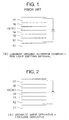
- the conventional organic EL element includes a transparent anode 12 made of ITO (indium-tin oxide), a hole injecting layer 13, a hole transporting layer 14, a luminescent layer 15, an electron transporting layer 16 and a cathode 17 sequentially stacked on a glass substrate 11.
- the luminescent layer 15 includes, as a host, an organic metal complex having a higher fluorescent quantum yield (general formula [a]), doped with the red light emitting material.
- the same or another organic metal complex (general formula [a]) having the electron transporting ability may be used in the electron transporting layer 16.
- the use of the hole injecting layer with the resistance to higher temperature provides the reduction of the recombination yield between the hole and the electron in the luminescent layer, accompanied by the change of the color shade. Accordingly, the organic EL device having the excellent luminescent efficiency, the higher brightness and the permanently stabilized chromaticity cannot be conventionally obtained. This is because the hole injecting ability into the luminescent layer is low, and the electron transporting ability is changed due to increase of a voltage so that the recombination normally occurring in the luminescent layer actually occurs in the hole transporting layer in place of the luminescent layer.
- an object of the present invention is to provide an organic EL element having the excellent luminescent efficiency, brightness and chromaticity.
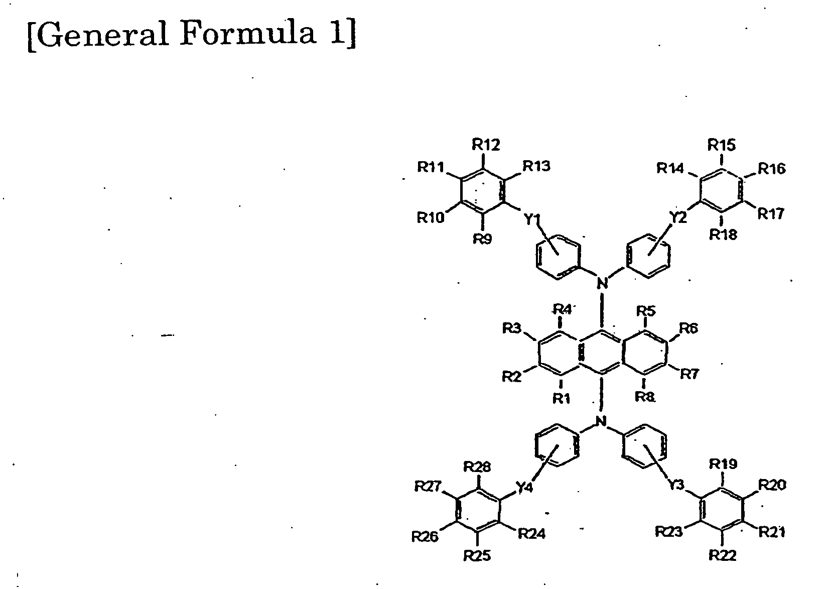
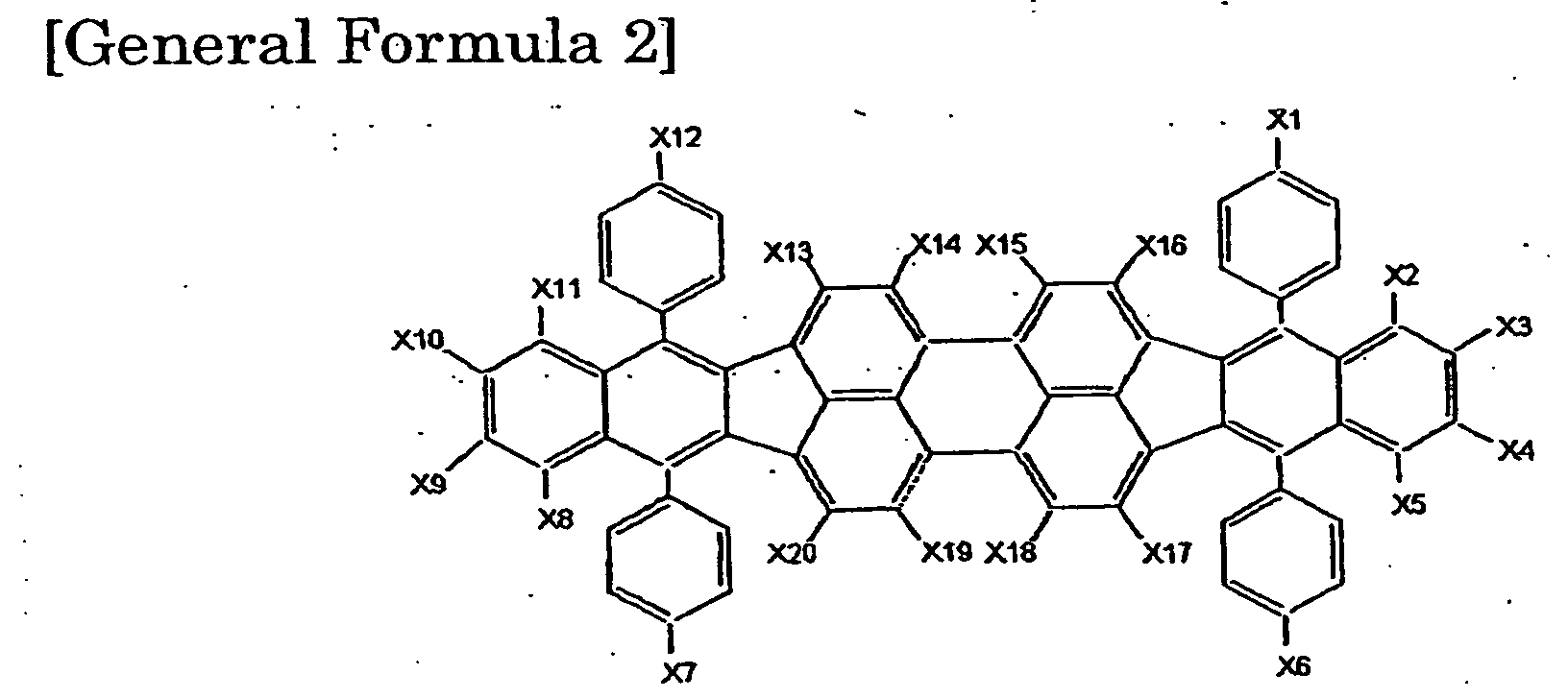
- the present invention provides an organic EL element including an anode and a cathode opposing to each other, and at least one luminescent layer, positioned therebetween, including an aromatic amine derivative designated by a general formula [1], [4], [5] or [6] and a dibenzo- ⁇ [f,f']-4,4',7,7'-tetraphenyl ⁇ -diindeno[1,2,3-cd:1',2',3'-lm] perylene derivative designated by a general formula [2].
- each of R1 to R 28 is independently selected from the group consisting of a hydrogen atom, a halogen atom, a substituted or non-substituted alkyl group, a substituted or non-substituted alkoxy group, a substituted or non-substituted aryl group and a substituted or non-substituted amino group
- two of R1 to R4 and/or two of R5 to R8 may be bonded to form a substituted or non-substituted five-membered or six-membered ring.
- each of R1 to R 28 is independently selected from the group consisting of a hydrogen atom, a halogen atom, a substituted or non-substituted alkyl group, a substituted or non-substituted alkoxy group, a substituted or non-substituted aryl group and a substituted or non-substituted amino group
- two of R1 to R4 and/or two of R5 to R8 may be bonded to form a substituted or non-substituted five-membered or six-membered ring.
- each of R1 to R 28 is independently selected from the group consisting of a hydrogen atom, a halogen atom, a substituted or non-substituted alkyl group, a substituted or non-substituted alkoxy group, a substituted or non-substituted aryl group and a substituted or non-substituted amino group
- each of X1 to X8 is independently selected from the group consisting of a substituted or non-substituted alkyl group having a carbon number of 1 to 20 and a substituted or non-substituted aryl group having a carbon number of 6 to 16
- two of R1 to R4 and/or two of R5 to R8 may be bonded to form a substituted or non-substituted five-membered or six-membered ring.
- each of R1 to R 28 is independently selected from the group consisting of a hydrogen atom, a halogen atom, a substituted or non-substituted alkyl group, a substituted or non-substituted alkoxy group, a substituted or non-substituted aryl group and a substituted or non-substituted amino group, and two of R1 to R4 and/or two of R5 to R8 may be bonded to form a substituted or non-substituted five-membered or six-membered ring.
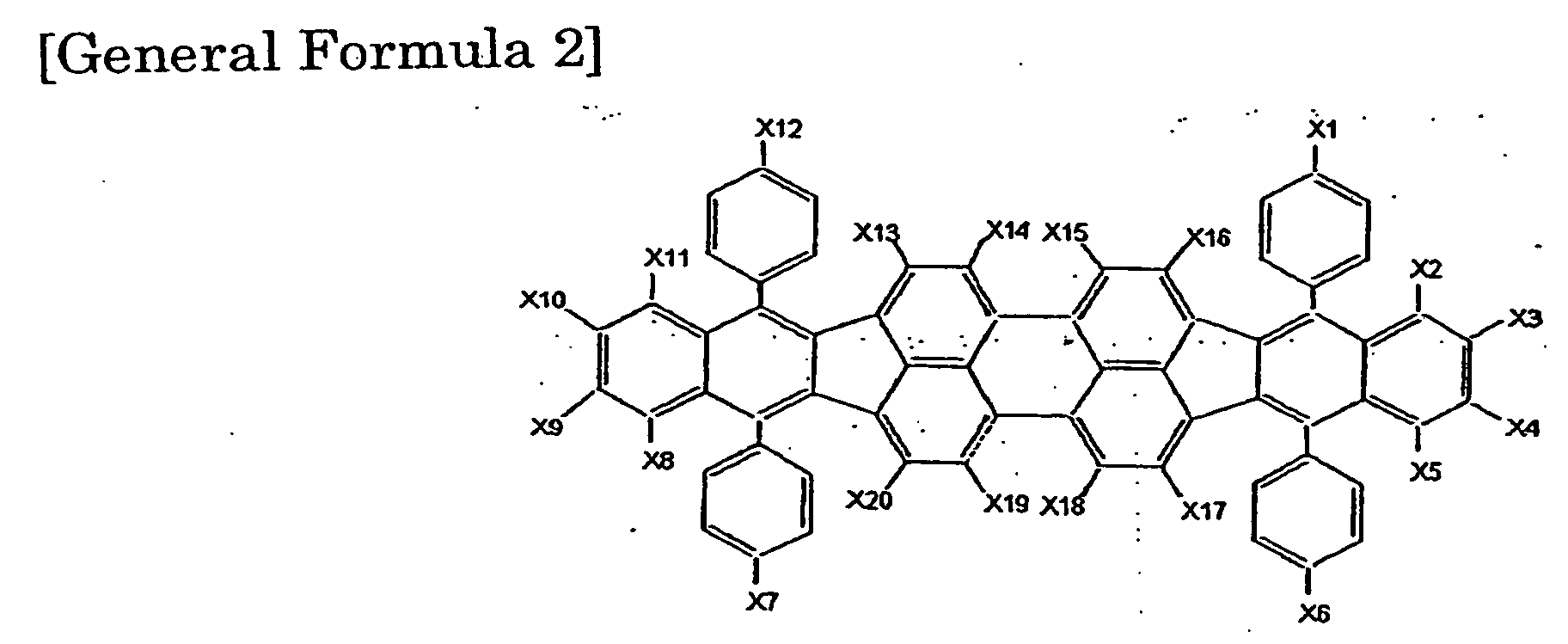
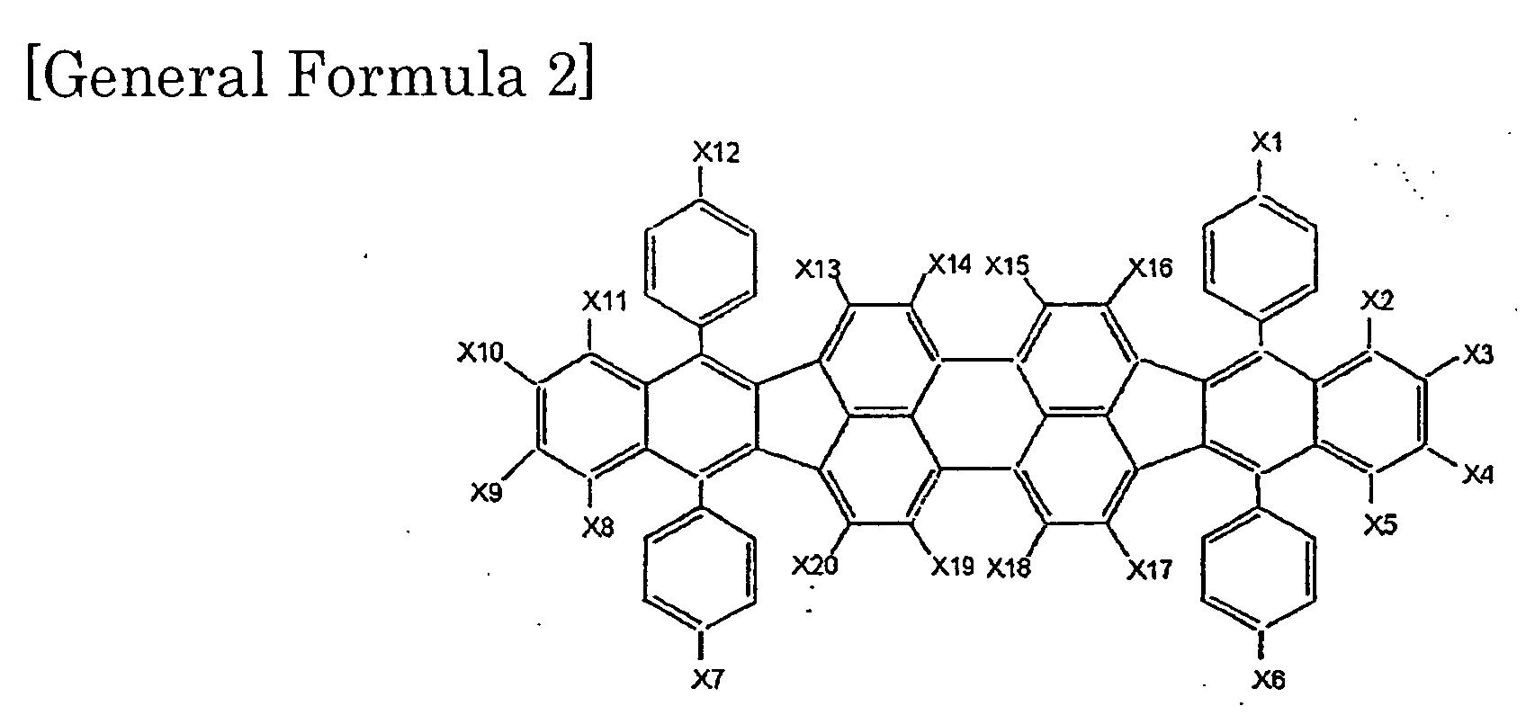
- each of X1 to X20 is independently selected from the group consisting of a hydrogen atom, a halogen atom, a substituted or non-substituted alkyl group, a substituted or non-substituted alkoxy group, a substituted or non-substituted aryl group and a substituted or non-substituted amino group, and two of X1 to X20 may be bonded to form a substituted or non-substituted five-membered or six-membered ring.
- the aromatic amine derivative and the perylene derivative in the luminescent layer can provide an excellent hole transporting ability (electron blocking ability) to the luminescent layer.
- the hole injecting efficiency into the luminescent layer is improved to elevate the recombination efficiency between the hole and the electron in the luminescent layer, thereby providing the higher brightness.
- the luminescent layer also acts as an electron blocking layer to prevent the permeation of the electron through the luminescent layer, thereby elevating the purity of the color.
- the organic EL display using the organic EL element also exhibits the excellent display characteristic.
- the brightness can be maintained higher. If one organic metal complex is used in the electron injection layer or the electron transporting layer, the agglomeration or the crystallization of the film tends to proceed to deteriorate the electron injecting property and the electron transporting property. On the other hand, two organic metal complexes in the layer increase the amorphous property. Accordingly, the agglomeration or the crystallization hardly occurs even after a longer period of time to suppress the decrease of the electron injecting property and the electron transporting property.
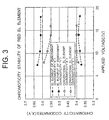
- an organic EL element of the present Embodiment includes a transparent anode 12 made of ITO (indium-tin oxide), a hole injecting layer 13, a hole transporting layer 14, a luminescent layer 15, an electron transporting layer 16 and a cathode 17 sequentially stacked on a glass substrate 11.
- the hole injecting layer 13 has an excellent resistance to higher temperature for improving the thermal stability of the organic EL element.
- the luminescent layer 15 includes an aromatic amine derivative designated by a general formula [1] and a dibenzo- ⁇ [f,f']-4,4',7,7'-tetraphenyl ⁇ -diindeno[1,2,3-cd:1',2',3'-lm] perylene derivative designated by a general formula [2] mixed with each other.
- the doping amount of the perylene derivative is controlled by a vapor deposition rate, and is preferably between 1 and 10 % with respect to the aromatic amine derivative for suppressing the concentration quenching of pigment itself.
- the luminescent layer 15 may be formed by stacked two layers each containing the above perylene derivative having the different doping amounts.
- the compound designated by the general formula [1] can be synthesized in accordance with a known process, for example, by reacting an anthracene derivative or an anthraquinone derivative with a substituted or non-substituted amine derivative under existence of potassium carbonate, sodium carbonate, potassium hydroxide or sodium hydroxide in a solvent such as benzene, toluene and xylene.
- a catalyst employable therefor includes copper powder, cuprous chloride, tin, stannous chloride and pyridine.
- the compound designated by the general formula [2] can be synthesized in accordance with a known process, for example, by reacting a benzo[k]fluoran derivative under existence of aluminum chloride/sodium chloride, cobalt fluoride or thallium trifluoroacetate.
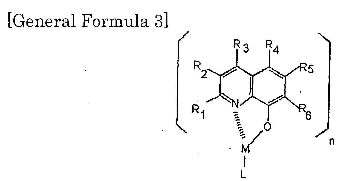
- the use of the organic metal complex designated by the general formula [3] having a higher ionization potential in the electron transporting layer 16 increases the ionization potential of the electron transporting layer larger than that of the luminescent layer.
- the hole blocking ability of the electron transporting layer 16 is improved for preventing the leakage of the hole into the electron transporting layer, thereby further elevating the recombination yield between the hole and the electron in the luminescent layer.
- the electron transporting material designated by the general formula [3] can also be synthesized in accordance with a known process, for example, by reacting a gallium compound with a compound having a part specified in a bracket of the general formula [3] and a ligand residue of "L".
- alkyl gallium, gallium alkoxide, gallium halogenide, gallium nitride or gallium oxide is reacted with a compound having, as the ligands in the brackets of the general formula [3], two ligands of a quinoline residue such as 8-hydroxyquinoline and 2-methyl-8- hydroxyquinoline and one ligand (for the "L" ligand) of a halogen atom, substituted or non-substituted alkoxy group, aryloxy group or alkyl group in a solvent such as methanol, ethanol-benzene, toluene and tetrahydrofuran.
- an aromatic amine derivative designated by a compound [1] shown below was doped with dibenzotetraphenylperyfurantene designated by a compound [2] shown below in a vapor deposition rate of 2.5 % to prepare a luminescent layer.
- An electron transporting layer was prepared by using a gallium metal complex designated by a compound [3] shown below.
- red light emission could be obtained having a current efficiency of 6 cd/A or more (up to 1,000 cd/m 2 ) and a maximum brightness of 38,000 cd/m 2 each of which was at the practical level.
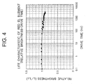
- the chromaticity stability of the organic EL element was excellent, and the change of the color shade due to the applied voltage was small.
- a graph of Fig.3 shows the relations between the applied voltage (V, abscissa) and the coordinates of "X" and "Y” of the CIE chromaticity (ordinate) of the organic EL element of the Example 1 and of the conventional organic EL element. As shown therein, the change of the color shade in the chromaticity "X" was suppressed when the applied voltage was increased, compared with the conventional EL element.
- the life characteristic of the organic EL element of the Example 1 at the constant current driving of 5 mA/cm 2 was improved.
- the organic EL element of the Example 1 maintained 90 % or more of the initial brightness even after the lapse of 3,000 hours. Further, dark spots (non-emitting section) were seldom observed.
- another luminescent layer was prepared by doping 4,4'-bis[N-phenyl-N- (1" -naphtyl)amino]biphenyl with the compound [2] at 5 % in weight.
- red light emission having brightness of 2,650 cd/m 2 was obtained by applying a direct voltage of 15 V.
- the brightness of the organic EL element after the stable and successive operation at the constant current for 2,700 hours was reduced as low as to 30 cd/m 2 .
- the brightness of the organic EL element was much lower than that of Example 1 and the period of life was short. Accordingly, the practical use thereof seemed difficult.
- the brightness and the luminescent efficiency were insufficient, and the brightness, the luminescent efficiency, the period of life and the chromaticity stability could be improved by using the metal complex of the general formula [3] as the electron transporting layer of the red EL element.
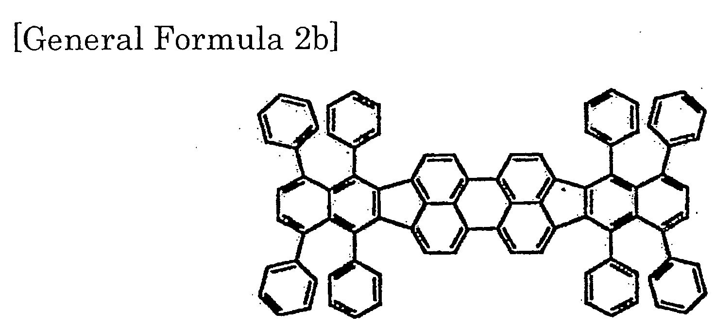
- the aromatic amine derivative designated by the compound I was doped with the compound [2b] at a vaporization rate of 2.5 % to fabricate the luminescent layer of the organic EL device of the present Example.
- the gallium metal complex [3a] was used to prepare the electron transporting layer.
- the organic EL device was fabricated in accordance with the procedures of Example 4 except that the gallium metal complexes [3a] and [3b] were used to prepare the electron transporting layer.
- the ratio between the gallium metal complexes [3a] and [3b] was 9:1 in weight.
- red light emission could be obtained having a current efficiency of 6.6 cd/A or more (up to 1,000 cd/m 2 ) and a maximum brightness of 43,000 cd/m 2 .
- the organic EL device was fabricated in accordance with the procedures of Example 4 except that the gallium metal complex [3] was used to prepare the electron transporting layer.
- the gallium metal complex [3] was used to prepare the electron transporting layer.
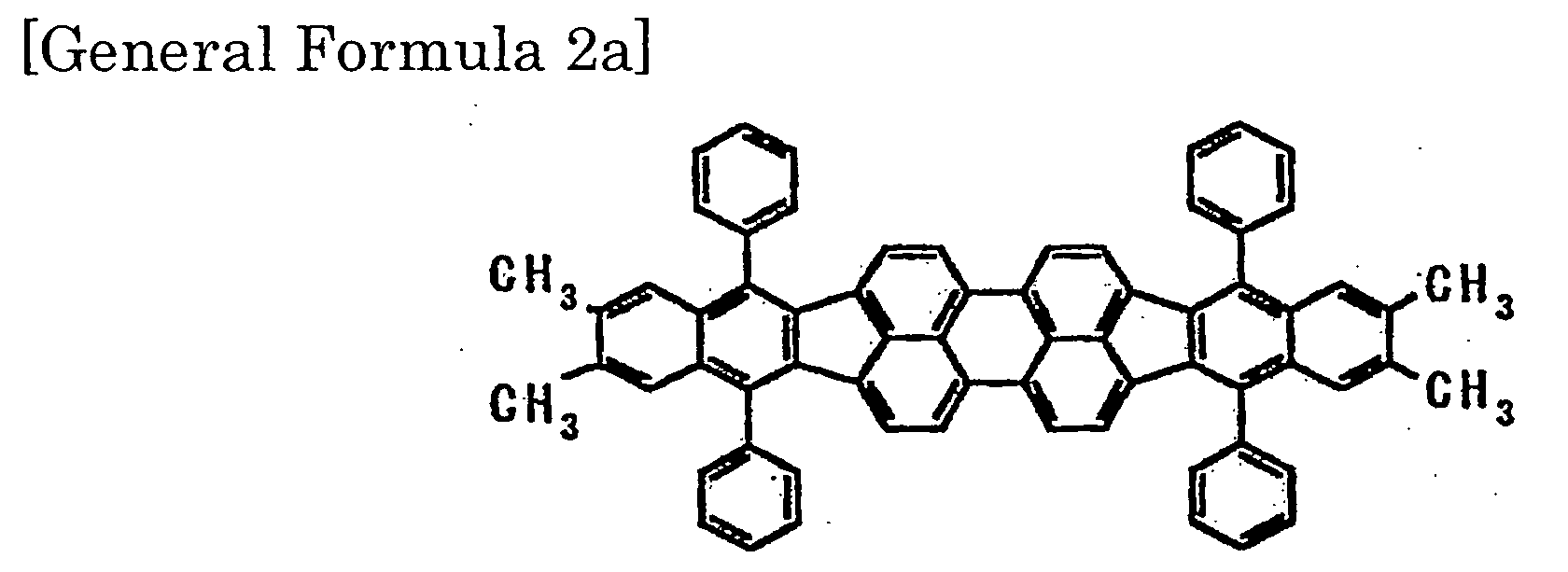
- the aromatic amine derivative designated by the compound I was doped with a compound of general formula [2a] at a vaporization rate of 2.5 % to fabricate the luminescent layer of the organic EL device of the present Example.
- the gallium metal complex [3a] was used to prepare the electron transporting layer.
- the organic EL device was fabricated in accordance with the procedures of Example 7 except that the gallium metal complexes [3a] and [3b] were used to prepare the electron transporting layer.
- the ratio between the gallium metal complexes [3a] and [3b] was 9:1 in weight.
- the organic EL device was fabricated in accordance with the procedures of Example 7 except that the gallium metal complex [3] was used to prepare the electron transporting layer.
- the gallium metal complex [3] was used to prepare the electron transporting layer.
- Example 1 Life Time at Room Temp. (hr)* Efficiency at 100cd/m 2 (cd/A) Maximum Brightness (cd/m 2 ) Life Time at 85 °C (hr) Chromaticity @1000 cd/m 2
- Example 1 10000 6 38000 500 (0.62,0.38)
- Example 4 15000 6.8 45000 1900 (0.63,0.36)
- Example 5 16000 6.6 43000 ⁇ 2000 (0.63,0.37)
- Example 6 10000 6 38000 700 Example 7 ⁇ 12000 6.5 42000 1600 (0.62,0.37)
- Example 8 ⁇ 12000 6.4 41000 ⁇ 2000 (0.62,0.37)
- Example 9 10000 5.8 37000 600 (0.62,0.38)
- the aromatic amine derivative designated by the compound I was doped with dibenzotetraphenylperifurantene of the compound [2] at a vaporization rate of 2.5 % to fabricate the luminescent layer.
- the gallium metal complex [3a] was used to prepare the electron transporting layer in the present Example.
- the L-V characteristic and the J-V characteristic of the device of Example 10 compared with a conventional device were shown in Figs.5A and 5B, respectively.
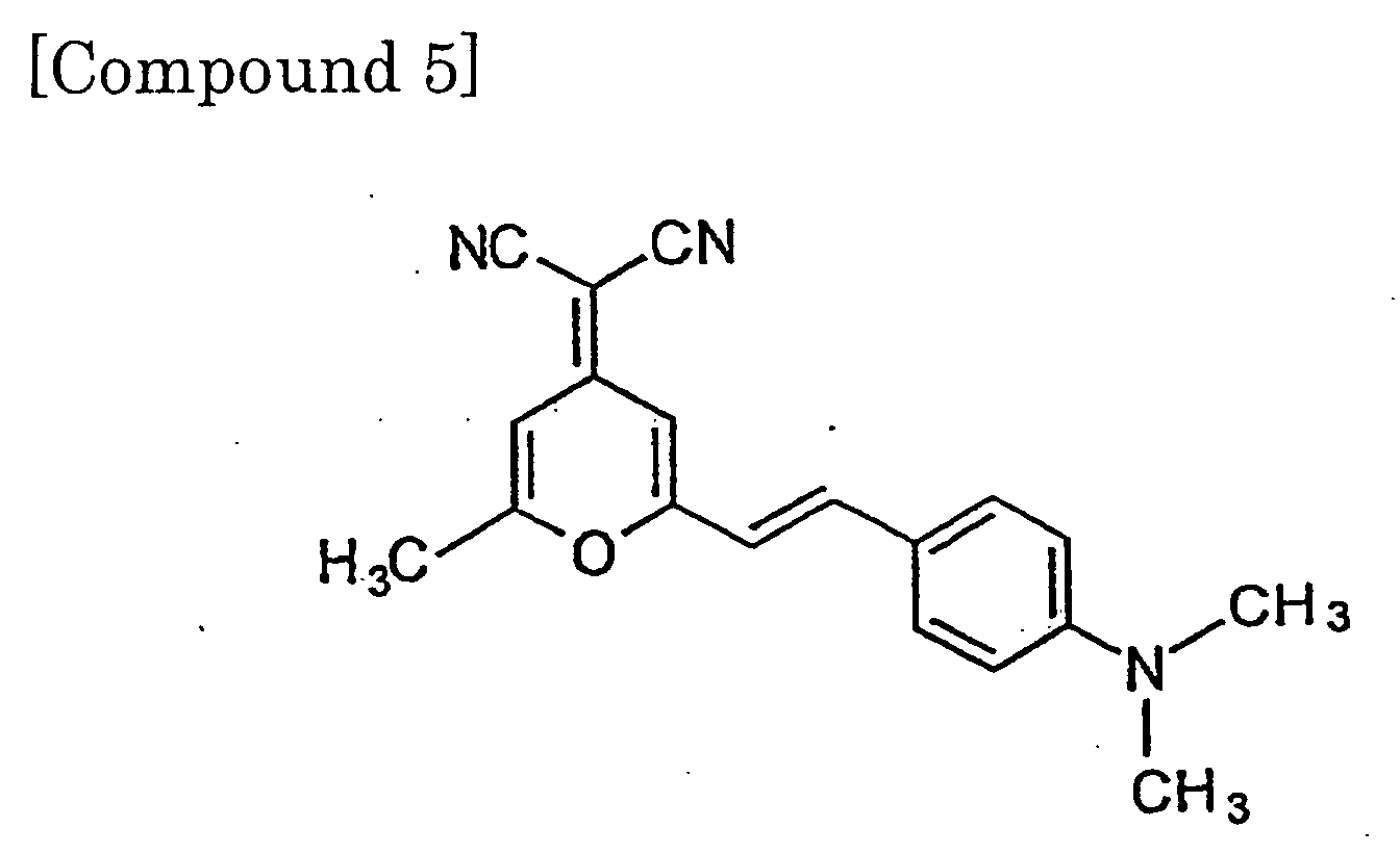
- the conventional device included the luminescent layer having tris-(8-quinolinolate) aluminum designated by the compound [4] doped with the red dopant (DCM) designated by the compound [5], and the electron transporting layer having tris-(8-quinolinolate) aluminum designated by the compound [4].
- the device of Example 10 could be operated at the lower voltage than the conventional red device.
Landscapes
- Physics & Mathematics (AREA)
- Spectroscopy & Molecular Physics (AREA)
- Chemical & Material Sciences (AREA)
- Engineering & Computer Science (AREA)
- Materials Engineering (AREA)
- Electroluminescent Light Sources (AREA)
Abstract

Description


| Life Time at Room Temp. (hr)* | Efficiency at 100cd/m2 (cd/A) | Maximum Brightness (cd/m2) | Life Time at 85 °C (hr) | Chromaticity @1000 cd/m2 | |
| Example 1 | 10000 | 6 | 38000 | 500 | (0.62,0.38) |
| Example 4 | 15000 | 6.8 | 45000 | 1900 | (0.63,0.36) |
| Example 5 | 16000 | 6.6 | 43000 | ≧2000 | (0.63,0.37) |
| Example 6 | 10000 | 6 | 38000 | 700 | (0.63,0.37) |
| Example 7 | ≧12000 | 6.5 | 42000 | 1600 | (0.62,0.37) |
| Example 8 | ≧12000 | 6.4 | 41000 | ≧2000 | (0.62,0.37) |
| Example 9 | 10000 | 5.8 | 37000 | 600 | (0.62,0.38) |
Claims (18)
- An organic EL element comprising an anode and a cathode opposing to each other, and at least one luminescent layer, sandwiched therebetween, including an aromatic amine derivative designated by a general formula [1] (wherein each of R1 to R 28 is independently selected from the group consisting of a hydrogen atom, a halogen atom, a substituted or non-substituted alkyl group, a substituted or non-substituted alkoxy group, a substituted or non-substituted aryl group and a substituted or non-substituted amino group, each of Y1 to Y4 is independently selected from the group consisting of O, S, SO2, C=O, CH2O, CH2OCH2 and a substituted or non-substituted alkylene group, and two of R1 to R4 and/or two of R5 to R8 may be bonded to form a substituted or non-substituted five-membered or six-membered ring) and a dibenzo{[f,f'] -4,4',7,7'-tetraphenyl}-diindeno[1,2,3-cd:1',2',3'-lm] perylene derivative designated by a general formula [2] (wherein each of X1 to X20 is independently selected from the group consisting of a hydrogen atom, a halogen atom, a substituted or non-substituted alkyl group, a substituted or non-substituted alkoxy group, a substituted or non-substituted aryl group and a substituted or non-substituted amino group, and two of X1 to X20 may be bonded to form a substituted or non-substituted five-membered or six-membered ring).

- An organic EL element comprising an anode and a cathode opposing to each other, and at least a luminescent layer, positioned therebetween, including an aromatic amine derivative designated by a general formula [4] (wherein each of R1 to R 28 is independently selected from the group consisting of a hydrogen atom, a halogen atom, a substituted or non-substituted alkyl group, a substituted or non-substituted alkoxy group, a substituted or non-substituted aryl group and a substituted or non-substituted amino group, each of Y1 to Y4 is independently selected from the group consisting of O, S, SO2, C=O, CH2O, CH2OCH2 and a substituted or non-substituted alkylene group, and two of R1 to R4 and/or two of R5 to R8 may be bonded to form a substituted or non-substituted five-membered or six-membered ring) and a dibenzo- {[f,f]-4,4',7,7'tetraphenyl}-diindeno[1,2,3-cd:1',2',3'-lm] perylene derivative designated by a general formula [2] (wherein each of X1 to X20 is independently selected from the group consisting of a hydrogen atom, a halogen atom, a substituted or non-substituted alkyl group, a substituted or non-substituted alkoxy group, a substituted or non-substituted aryl group and a substituted or non-substituted amino group, and two of X1 to X20 may be bonded to form a substituted or non-substituted five- non-substituted five-membered or six-membered ring).

- An organic EL element comprising an anode and a cathode opposing to each other, and at least a luminescent layer, positioned therebetween, including an aromatic amine derivative designated by a general formula [5] (wherein each of R1 to R 28 is independently selected from the group consisting of a hydrogen atom, a halogen atom, a substituted or non-substituted alkyl group, a substituted or non-substituted alkoxy group, a substituted or non-substituted aryl group and a substituted or non-substituted amino group, each of X1 to X8 is independently selected from the group consisting of a substituted or non-substituted alkyl group having a carbon number of 1 to 20 and a substituted or non-substituted aryl group having a carbon number of 6 to 16, and two of R1 to R4 and/or two of R5 to R8 may be bonded to form a substituted or non-substituted five-membered or six-membered ring) and a dibenzo{[f,f'] -4,4',7,7'-tetraphenyl}-diindeno[1,2,3-cd:1',2',3'-lm] perylene derivative designated by a general formula [2] (wherein each of X1 to X20 is independently selected from the group consisting of a hydrogen atom, a halogen atom, a substituted or non-substituted alkyl group, a substituted or non-substituted alkoxy group, a substituted or non-substituted aryl group and a substituted or non-substituted amino group, and two of X1 to X20 may be bonded to form a substituted or non-substituted five-membered or six-membered ring).

- An organic EL element comprising an anode and a cathode opposing to each other, and at least a luminescent layer, positioned therebetween, including an aromatic amine derivative designated by a general formula [6] (wherein each of R1 to R 28 is independently selected from the group consisting of a hydrogen atom, a halogen atom, a substituted or non-substituted alkyl group, a substituted or non-substituted alkoxy group, a substituted or non-substituted aryl group and a substituted or non-substituted amino group, and two of R1 to R4 and/or two of R5 to R8 may be bonded to form a substituted or non-substituted five-membered or six-membered ring) and a dibenzo{[f,f']-4,4',7,7'-tetraphenyl}-diindeno[1,2,3-cd:1',2',3'-lm] perylene derivative designated by a general formula [2] (wherein each of X1 to X20 is independently selected from the group consisting of a hydrogen atom, a halogen atom, a substituted or non-substituted alkyl group, a substituted or non-substituted alkoxy group, a substituted or non-substituted aryl group and a substituted or non-substituted amino group, and two of X1 to X20 may be bonded to form a substituted or non-substituted five-membered or six-membered ring).

- The organic EL element as defined in claim 1, wherein the dibenzo-{[f,f']-4,4',7,7'-tetraphenyl}diindeno[1,2,3-cd:1',2',3'-lm] perylene derivative designated by the general formula [2] is a compound designated by a general formula [2a].
- The organic EL element as defined in claim 1, wherein the dibenzo-{[f,f']-4,4',7,7'-tetraphenyl}diindeno[1,2,3-cd:1',2',3'-lm] perylene derivative designated by the general formula [2] is a compound designated by a general formula [2b].
- The organic EL element as defined in claim 1, wherein the aromatic amine derivative designated by the general formula [1] is used as a host doped with the perylene derivative designated by the general formula [2] at a doping ratio between 1 and 10 %.
- The organic EL element as defined in claim 2, wherein the aromatic amine derivative designated by the general formula [4] is used as a host doped with the perylene derivative designated by the general formula [2] at a doping ratio between 1 and 10 %.
- The organic EL element as defined in claim 3, wherein the aromatic amine derivative designated by the general formula [5] is used as a host doped with the perylene derivative designated by the general formula [2] at a doping ratio between 1 and 10 %.
- The organic EL element as defined in claim 4, wherein the aromatic amine derivative designated by the general formula [6] is used as a host doped with the perylene derivative designated by the general formula [2] at a doping ratio between 1 and 10 %.
- The organic EL element as defined in claim 1 further comprising an electron injection layer or an electron transporting layer including an organic metal complex designated by a general formula [3] (wherein X designates a metal atom, each of R1 to R 6 is independently selected from the group consisting of a hydrogen atom, a halogen atom, a substituted or non-substituted alkyl group, a substituted or non-substituted alkoxy group, a substituted or non-substituted aryl group, a substituted or non-substituted aryloxy group, a substituted or non-substituted cycloalkyl group and a cyano group, L designates a ligand having a halogen atom, a substituted or non-substituted alkoxy group, a substituted or non-substituted aryloxy group, a substituted or non-substituted alkyl group or a substituted or non-substituted cycloalkyl group).
- The organic EL element as defined in claim 11, wherein the R4 of the organic metal complex of the general formula [3] is the aryl group.
- The organic EL element as defined in claim 11, wherein the organic metal complex of the general formula [3] is a compound designated by a general formula [3a].

- The organic EL element as defined in claim 11, wherein the organic metal complex of the general formula [3] is a compound designated by a general formula [3b].

- The organic EL element as defined in claim 11, wherein the electron injection layer or the electron transporting layer includes a plurality of the organic metal complexes designated by the general formula [3].
- The organic EL element as defined in claim 11, wherein the electron injection layer or the electron transporting layer includes the compounds designated by the general formulae [3a] and [3b].
- The organic EL element as defined in claim 11, wherein the electron injection layer or the electron transporting layer includes a luminescent organic aluminum complex designated by (Q)3-Al (wherein "Q" is a substituted or non-substituted 8-quinolinolate ligand).
- An organic EL display comprising the organic EL element as defined in claim 1.
Applications Claiming Priority (2)
| Application Number | Priority Date | Filing Date | Title |
|---|---|---|---|
| JP2001042102 | 2001-02-19 | ||
| JP2001042102A JP3688207B2 (en) | 2000-02-18 | 2001-02-19 | Organic EL device and organic EL display |
Publications (3)
| Publication Number | Publication Date |
|---|---|
| EP1235466A2 true EP1235466A2 (en) | 2002-08-28 |
| EP1235466A3 EP1235466A3 (en) | 2005-08-17 |
| EP1235466B1 EP1235466B1 (en) | 2018-10-03 |
Family
ID=18904448
Family Applications (1)
| Application Number | Title | Priority Date | Filing Date |
|---|---|---|---|
| EP01119918.9A Expired - Lifetime EP1235466B1 (en) | 2001-02-19 | 2001-08-17 | Organic electroluminescent element and organic electroluminescent display |
Country Status (1)
| Country | Link |
|---|---|
| EP (1) | EP1235466B1 (en) |
Cited By (1)
| Publication number | Priority date | Publication date | Assignee | Title |
|---|---|---|---|---|
| EP1435669A3 (en) * | 2002-12-31 | 2007-07-04 | Eastman Kodak Company | Efficient electroluminescent device |
Family Cites Families (4)
| Publication number | Priority date | Publication date | Assignee | Title |
|---|---|---|---|---|
| EP0765106B1 (en) * | 1995-09-25 | 2002-11-27 | Toyo Ink Manufacturing Co., Ltd. | Light-emitting material for organic electroluminescence device, and organic electroluminescence device for which the light-emitting material is adapted |
| JP3824417B2 (en) * | 1997-04-04 | 2006-09-20 | 三井化学株式会社 | Hydrocarbon compounds and organic electroluminescent devices |
| JP3357857B2 (en) * | 1998-07-24 | 2002-12-16 | 出光興産株式会社 | Organic electroluminescence device and method of manufacturing the same |
| KR100869622B1 (en) * | 1998-12-28 | 2008-11-21 | 이데미쓰 고산 가부시키가이샤 | A material for organic electroluminescent element and an organic electroluminescent element comprising same |
-
2001
- 2001-08-17 EP EP01119918.9A patent/EP1235466B1/en not_active Expired - Lifetime
Cited By (1)
| Publication number | Priority date | Publication date | Assignee | Title |
|---|---|---|---|---|
| EP1435669A3 (en) * | 2002-12-31 | 2007-07-04 | Eastman Kodak Company | Efficient electroluminescent device |
Also Published As
| Publication number | Publication date |
|---|---|
| EP1235466A3 (en) | 2005-08-17 |
| EP1235466B1 (en) | 2018-10-03 |
Similar Documents
| Publication | Publication Date | Title |
|---|---|---|
| US6689493B2 (en) | Organic electroluminescent element and organic electroluminescent display | |
| US7026480B2 (en) | Organometallic light-emitting material | |
| KR100803125B1 (en) | Red phosphorescent compound and organic light emitting device using the same | |
| CN100469204C (en) | organic electroluminescent element | |
| US7504163B2 (en) | Hole-trapping materials for improved OLED efficiency | |
| EP1265298A2 (en) | Organic light-emitting device having a color-neutral dopant in a hole-transport layer and/or in an electron-transport layer | |
| EP1298737A2 (en) | Organic light emitting diode having an interface layer between the hole-transporting layer and the light-emitting layer | |
| EP1286568A1 (en) | Organic light-emitting device having a color-neutral dopant | |
| JP2006140434A (en) | Organic electroluminescence device | |
| KR101517903B1 (en) | High-Performance Broadband OLED Device | |
| KR20110110172A (en) | Improved OLD stability through doped hole transport layer | |
| KR101494789B1 (en) | Organic light emitting material and organic light emitting element using the same | |
| KR101989667B1 (en) | Organic electroluminescent devices | |
| WO2011011501A1 (en) | Oled device with stabilized yellow light-emitting layer | |
| US20040142206A1 (en) | Binaphthol based chromophores for the fabrication of blue organic light emitting diodes | |
| JP3688207B2 (en) | Organic EL device and organic EL display | |
| KR100525409B1 (en) | organic electroluminescence device | |
| USH2084H1 (en) | Pentacene derivatives as red emitters in organic light emitting devices | |
| EP2232611B1 (en) | Barrier coated substrate and electro-optical device | |
| US20010028961A1 (en) | Organic electroluminescent element and organic electroluminescent display | |
| EP1235466B1 (en) | Organic electroluminescent element and organic electroluminescent display | |
| WO2002022760A1 (en) | Organic electro-luminescence device | |
| KR100354861B1 (en) | Organic electroluminescent device | |
| KR19990086810A (en) | High melting point complex and organic light emitting device comprising the same | |
| KR100552961B1 (en) | Organic electroluminescent display device |
Legal Events
| Date | Code | Title | Description |
|---|---|---|---|
| PUAI | Public reference made under article 153(3) epc to a published international application that has entered the european phase |
Free format text: ORIGINAL CODE: 0009012 |
|
| AK | Designated contracting states |
Kind code of ref document: A2 Designated state(s): AT BE CH CY DE DK ES FI FR GB GR IE IT LI LU MC NL PT SE TR |
|
| AX | Request for extension of the european patent |
Free format text: AL;LT;LV;MK;RO;SI |
|
| RAP1 | Party data changed (applicant data changed or rights of an application transferred) |
Owner name: SAMSUNG SDI CO., LTD. |
|
| PUAL | Search report despatched |
Free format text: ORIGINAL CODE: 0009013 |
|
| AK | Designated contracting states |
Kind code of ref document: A3 Designated state(s): AT BE CH CY DE DK ES FI FR GB GR IE IT LI LU MC NL PT SE TR |
|
| AX | Request for extension of the european patent |
Extension state: AL LT LV MK RO SI |
|
| RIC1 | Information provided on ipc code assigned before grant |
Ipc: 7C 09K 11/06 B Ipc: 7H 01L 51/30 A |
|
| 17P | Request for examination filed |
Effective date: 20060213 |
|
| AKX | Designation fees paid |
Designated state(s): DE GB |
|
| RAP1 | Party data changed (applicant data changed or rights of an application transferred) |
Owner name: SAMSUNG MOBILE DISPLAY CO., LTD. |
|
| RAP1 | Party data changed (applicant data changed or rights of an application transferred) |
Owner name: SAMSUNG DISPLAY CO., LTD. |
|
| RAP1 | Party data changed (applicant data changed or rights of an application transferred) |
Owner name: SAMSUNG DISPLAY CO., LTD. |
|
| STAA | Information on the status of an ep patent application or granted ep patent |
Free format text: STATUS: EXAMINATION IS IN PROGRESS |
|
| GRAP | Despatch of communication of intention to grant a patent |
Free format text: ORIGINAL CODE: EPIDOSNIGR1 |
|
| STAA | Information on the status of an ep patent application or granted ep patent |
Free format text: STATUS: GRANT OF PATENT IS INTENDED |
|
| INTG | Intention to grant announced |
Effective date: 20180403 |
|
| GRAS | Grant fee paid |
Free format text: ORIGINAL CODE: EPIDOSNIGR3 |
|
| GRAA | (expected) grant |
Free format text: ORIGINAL CODE: 0009210 |
|
| STAA | Information on the status of an ep patent application or granted ep patent |
Free format text: STATUS: THE PATENT HAS BEEN GRANTED |
|
| AK | Designated contracting states |
Kind code of ref document: B1 Designated state(s): DE GB |
|
| REG | Reference to a national code |
Ref country code: GB Ref legal event code: FG4D |
|
| REG | Reference to a national code |
Ref country code: DE Ref legal event code: R096 Ref document number: 60150959 Country of ref document: DE |
|
| RIC2 | Information provided on ipc code assigned after grant |
Ipc: C09K 11/06 20060101ALI20050627BHEP Ipc: H01L 51/30 20060101AFI20050627BHEP |
|
| REG | Reference to a national code |
Ref country code: DE Ref legal event code: R097 Ref document number: 60150959 Country of ref document: DE |
|
| PLBE | No opposition filed within time limit |
Free format text: ORIGINAL CODE: 0009261 |
|
| STAA | Information on the status of an ep patent application or granted ep patent |
Free format text: STATUS: NO OPPOSITION FILED WITHIN TIME LIMIT |
|
| 26N | No opposition filed |
Effective date: 20190704 |
|
| GBPC | Gb: european patent ceased through non-payment of renewal fee |
Effective date: 20190817 |
|
| PG25 | Lapsed in a contracting state [announced via postgrant information from national office to epo] |
Ref country code: GB Free format text: LAPSE BECAUSE OF NON-PAYMENT OF DUE FEES Effective date: 20190817 |
|
| PGFP | Annual fee paid to national office [announced via postgrant information from national office to epo] |
Ref country code: DE Payment date: 20200806 Year of fee payment: 20 |
|
| REG | Reference to a national code |
Ref country code: DE Ref legal event code: R071 Ref document number: 60150959 Country of ref document: DE |