EP1235446A2 - Wireless base station and method for maintaining same - Google Patents
Wireless base station and method for maintaining same Download PDFInfo
- Publication number
- EP1235446A2 EP1235446A2 EP01123925A EP01123925A EP1235446A2 EP 1235446 A2 EP1235446 A2 EP 1235446A2 EP 01123925 A EP01123925 A EP 01123925A EP 01123925 A EP01123925 A EP 01123925A EP 1235446 A2 EP1235446 A2 EP 1235446A2
- Authority
- EP
- European Patent Office
- Prior art keywords
- maintenance
- base station
- wireless base
- block
- wireless
- Prior art date
- Legal status (The legal status is an assumption and is not a legal conclusion. Google has not performed a legal analysis and makes no representation as to the accuracy of the status listed.)
- Withdrawn
Links
Images


Classifications
-
- H—ELECTRICITY
- H04—ELECTRIC COMMUNICATION TECHNIQUE
- H04B—TRANSMISSION
- H04B17/00—Monitoring; Testing
-
- H—ELECTRICITY
- H04—ELECTRIC COMMUNICATION TECHNIQUE
- H04W—WIRELESS COMMUNICATION NETWORKS
- H04W24/00—Supervisory, monitoring or testing arrangements
Definitions
- the present invention relates to a wireless base station in a mobile wireless system and a method for maintaining same.
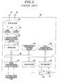
- FIG. 2 there is shown a functional block diagram of a conventional wireless base station 20.
- a radio wave received by a reception antenna 22 is transmitted to a low noise amplification (LNA) block 25 via a duplexer (DUP) block 23.
- the LNA block 25 amplifies the received radio wave and transmits the amplified radio wave to a modulation/demodulation (MODEM) block 26, which converts the amplified radio wave into a baseband signal to transmit same to a baseband processing (BB) block 27.
- the BB block 27 performs an error correction and a deframing of the baseband signal, demodulates data of the baseband signal and then transmits the demodulated data to an interface 35.
- the interface 35 delivers the demodulated data to a wire transmission line interface (I/F) block 30 that sends the demodulated data to a wire transmission line.
- I/F wire transmission line interface
- a signal inputted from the wire transmission line is delivered to the BB block 27 via the interface 35 and the wire transmission line I/F block 30.
- the BB block 27 performs the error correction and framing of the input signal, modulates data of the input signal and transmits the modulated data to the MODEM block 26.
- the MODEM block 26 converts the modulated data into a quadrature modulated radio frequency signal and transmits same to an amplification (AMP) block 24.
- the AMP block 24 amplifies a power of the modulated radio frequency signal up to a predetermined level and then a transmission antenna 21 transmits the amplified radio frequency signal.
- a supervisory control block 28 monitors a state of the wireless base station 20 and a call processing control block 29 takes charge of the management, the establishment and the release of a wireless line.
- a system data memory (SDM) block 31 is a memory for storing program or data file required by the wireless base station 20 and a file load (FLD) block 32 locally performs an operation of file in a memory medium section 33 where a program or a data file required by the wireless base station 20 is stored.
- the memory medium section 33 uses, e.g., a PC card as a memory medium, and a switch (SW) section 34 serves to select the data file to be loaded from the memory medium section 33.
- the interface 35 which is implemented with, e.g., PCI/VME bus, ATM, LAN or the like, interfaces each functional block of the wireless base station 20.
- the wireless base station 20 is constituted of a housing body incorporating a plurality of circuit boards or cards received in its slots, each of the boards having thereon one of the functional blocks shown in Fig. 2.
- Fig. 3 illustrates a schematic view of the housing body incorporating therein the boards. As exemplified in Fig. 3, each board is arranged in the order of the DUP block 23, the AMP block 24, the LNA block 25, the modulation/ demodulation block 26, the BB block 27, the supervisory control block 28, the call processing control block 29, the wire transmission line I/F block 30, the SDM block 31 and the FLD block 32, wherein the board of the FLD block 32 has the SW section 34 and the memory media section 33 therein.
- Each board has light emission diode (LED) ramps for presenting the state of a corresponding functional block, a maintenance connector for repairing and debugging the corresponding functional block, and a reset switch (RST_SW) on its front panel.
- LED light emission diode
- RST_SW reset switch
- the state presentation ramps such as an ACT_LED, an ALM_LED, an ERR_LED and a BLK_LED, wherein the ACT_LED lights up when the corresponding functional block operates normally, the ALM_LED lights up in case where an operation error or failure occurs in the corresponding functional block, the ERR_LED lights up in case where a communication error occurs between the corresponding functional block and another functional block, and the BLK_LED lights up in case where the corresponding block is blocked.
- a maintenance work is performed on the board-by-board basis allotted for a specific functional block shown in Fig. 2, it is desirable to provide a board serving as a maintenance unit with LEDs, a maintenance connector and a reset switch for presenting a state and resetting an operation of the corresponding functional part.
- the maintenance personnel has to directly inspect the wireless base station 20. For instance, the maintenance personnel should come to the housing body of the wireless base station 20 and look into the state presentation ramps on each board of the housing body to find out whether or not an error occurred in a functional block. If the LEDs indicate that an error has occurred in a functional block, data communications to and from the fault functional block has to be carried out for the maintenance thereof through the corresponding maintenance connector, when necessary.
- the requested program or data has to be loaded by inserting a memory medium into the memory medium section 33 and manipulating the SW section 34.
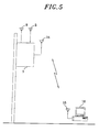
- the required number of wireless base stations has also been increased in proportion thereto. Accordingly, the size of a wireless base station needs to be scaled down in order to facilitate the acquisition of the installation site of the wireless base stations. Further, because an ultra-small capacity wireless base station serving, e.g., only dozens of communications channels sometimes needs to be installed on a utility pole such as a telephone or an electric pole, it has also become important to develop a scheme capable of facilitating the manipulation and maintenance of the wireless base station.
- each functional block serving as a maintenance unit shown in Fig. 2 has to be identified. Therefore, a functional part is mounted in one board, which is provided with the state presentation ramps, the maintenance connector and the reset switch thereon as described above.
- the surface of each board may not be fully utilized, leaving some unoccupied space therein; and thus such architecture is not suitable for the miniaturization of the wireless base station.
- the maintenance personnel since the maintenance personnel has to reach each board in person for the maintenance thereof, the installation of the wireless base station on a utility pole would cause the maintenance problem. Therefore, there has been required to develop a method capable of maintaining a wireless base station from a remote place.
- an object of the present invention to provide a miniaturized wireless base station capable of being remotely maintained without having to gain a direct access thereto, and a method for remotely maintaining same.
- a wireless base station of a mobile wireless system including:
- a method for maintaining a wireless base station including the step of:
- a method for maintaining a wireless base station including the step of:
- a block diagram for illustrating a wireless base station 1 in accordance with a preferred embodiment of the present invention wherein a duplexer (DUP) 4 is connected to a transmission antenna 2, a reception antenna 3 and a wireless processing block 5.
- DUP duplexer
- the wireless processing block 5 incorporates therein parts corresponding to the amplification (AMP) block 24, the low noise amplification (LNA) block 25 and the modulation/demodulation (MODEM) block 26 shown in Fig. 2.
- the wireless processing block 5 converts a signal provided from the baseband processing (BB) block 6 into a quadrature modulated signal.
- the modulated signal is transmitted from the transmission antenna 2 via the DUP block 4.
- the wireless processing block 5 also demodulates a wireless frequency signal received by the reception antenna 3 and provided through the DUP block 4.
- the baseband processing block 6 performs an error correction encoding, a framing and a data modulation of a transmission signal; and an error correction decoding, a deframing and a data demodulation of the received signal from the wireless processing block 5.
- An interface 12 which is implemented with, e.g., PCI/VME bus, ATM, LAN or the like, is an interface for blocks of the wireless base station 1.
- a wire transmission line I/F block 7 similarly acts as the wire transmission line I/F block 30 of Fig. 2 and functions as an interface with the wire transmission line.
- a control block 8 is an integrated block having therein the supervisory control block 28, the call processing control block 29, the system data memory (SDM) block 31 and the file load (FLD) block 32 shown in Fig. 2.
- the control block 8 monitors the state of the wireless base station 1, carries out a management, an establishment and a release of a wireless line and controls the system data memory, which stores a program and a data file of the wireless base station 1, and file loading from a memory medium.
- a memory medium section 9 and a switch (SW) section 10 similarly act as the memory medium section 33 and the SW section 34 shown in Fig. 2, respectively.
- the memory medium section 9 serves to locally load the program or the data file of the wireless base station 1 from the memory medium.
- a PC memory or the like can be used as the memory medium.
- the switch section 10 locally controls the loading of programs or data files from the memory medium section 9.
- the wireless base station 1 communicates with a maintenance terminal 16 by way of a maintenance block 11.
- the maintenance block 11 which includes a maintenance transceiver part 111, a maintenance control part 112 and a maintenance memory 113, is connected to a maintenance antenna 14, thereby transmitting maintenance information representing states of the functional blocks of the wireless base station 1 to the maintenance terminal 16 and receiving maintenance control information therefrom.
- the maintenance terminal 16 includes a maintenance terminal antenna 15 and a wireless transceiver part (not shown).
- the maintenance block 11 and the maintenance terminal 16 form a wireless link between the maintenance antenna 14 and the maintenance terminal antenna 15. Such wireless link can be implemented by using, e.g., the Bluetooth.
- the maintenance control part 112 of the maintenance block 11 is connected to other parts of the wireless base station 1 through a control line 13 so as to receive and monitor the states of the functional blocks and transmit to a functional block a control signal for enabling, e.g., the resetting or the blocking thereof when necessary.
- the maintenance terminal 16 displays the states of the functional blocks of the wireless base station 1 on a display screen thereof and provides, if necessary, the maintenance block 11 with a control signal for instructing, e.g., resetting or blocking a certain functional block or downloading a software.
- the interface 12 is connected to the baseband processing block 6, the wire transmission line I/F block 7, the control block 8 and the maintenance block 11, thereby enabling the data communications therebetween.
- Each of the DUP block 4, the wireless processing block 5, the baseband processing block 6, the wire transmission line I/F block 7 and the control block 8 corresponds to one hardware board of the wireless base station 1. That is, three boards of the AMP block 24, the LNA block 25 and the modulation/demodulation block 26 in the prior art wireless base station 20 shown in Figs. 2 and 3 are integrated into one board of the wireless processing part 5 in accordance with the present invention, which facilitates the scale-down of the wireless base station 1.
- control block 8 is a block that integrates four conventional boards of the supervisory control block 28, the call processing control block 29, the SDM block 31 and the FLD block 32 into one board.
- the boards of the present invention are made not to include any of such parts required for maintenance in the prior art, e.g., LEDs, a connector and a reset switch provided on each board in the conventional wireless base station 20. Therefore, by removing such maintenance parts from the boards, the size of the boards of the present invention can be made smaller than that of the conventional board, which further facilitates the miniaturization of the wireless base station.
- the wireless base station 1 of the present invention has been described to include the memory medium section 9 and the switch section 10.
- the memory medium section 9 and the switch section 10 may be removed from the wireless base station 1 and the maintenance terminal 16 can be configured to perform their operations on behalf of them.
- the program or the system data which used to be stored in a memory medium used in connection with the memory medium section 9 of the prior art can be stored in a memory medium 17 (for example, if the maintenance terminal 16 is a personal computer, a CD or a FD can be used as the memory medium 17) used by the maintenance terminal 16.
- the memory medium 17 is inserted into the maintenance terminal 16 and the data of the memory medium 17 is loaded to the maintenance memory 113 of the maintenance block 11 via the maintenance wireless link.
- Such architecture helps the wireless base station 1 to be further miniaturized.
- the data indicating the state detected at each part of the wireless base station 1, i.e., the maintenance information, is collected by the maintenance control part 112 via the control line 13 and then stored in the maintenance memory 113.
- the maintenance information is transmitted through the wireless link and received by the maintenance terminal 16.
- the maintenance information includes, for example, a bit error rate (BER) for representing a quality of service (QoS), such as a quality of a voice data service or a quality of data communications, a desired wave level and an interference wave level of a wireless channel, a signal to noise power ratio, a code domain power and the like.
- BER bit error rate
- QoS quality of service
- the maintenance information may also include fault indication data identifying, for example, abnormalities in power and temperature, a synthesizer malfunction, an output overshoot, an automatic gain control (AGC) error and a sequential access method (SAM) error of a non-volatile memory.
- AGC automatic gain control
- SAM sequential access method
- the maintenance terminal 16 Upon receiving the maintenance information, the maintenance terminal 16 displays, e.g., the BER or a warning message indicating the warning state, or sounds an alarm when necessary.
- the maintenance terminal 16 transmits the maintenance control information to the maintenance block 11 through the wireless link and the maintenance block 11 stores the received maintenance control information in the maintenance memory 113.
- the maintenance control part 112 controls parts of the wireless base station 1 based on the maintenance control information stored in the maintenance memory 113.
- the maintenance control information includes, e.g., an update control signal for updating system parameters for controlling a gain of the LNA part of the wireless processing block 5 and the like, and a monitoring request signal requesting the monitoring of internal state parameters, and so on.
- the maintenance terminal 16 recognizes whether or not there is an error in a certain part of the wireless base station 1 by the help of the maintenance information provided from the maintenance block 11. If a certain part of the wireless base station 1 is determined to be erroneous, the corresponding part is first reset so as to restore the part into its normal state. Such a resetting operation can be performed manually by an operator of the maintenance terminal 16, e.g., by the operator's manipulation of a mouse or a keyboard of the maintenance terminal 16 in response to the maintenance information displayed thereon.
- the control operation can also be carried out automatically under a control of a control software of the maintenance terminal 16, which is configured to automatically generate and transmit the maintenance control information to the wireless base station 1.
- the maintenance terminal 16 upon receipt of the maintenance information indicating a fault or erroneous state, the maintenance terminal 16 identifies a board and further a functional block therein serving as a maintenance unit in which the error occurred, and transmits a reset signal for the identified functional block as the maintenance control information to the maintenance block 11 of the wireless base station 1.
- the control software resets the maintenance terminal 16 itself by means of, e.g., a watchdog timer.
- the preferred embodiment of the present invention has been described under the assumption that collecting the maintenance information and transmitting the maintenance control information from and to each part are carried out through the control line 13. Since, however, the maintenance block 11 in accordance with the present invention is also connected to the baseband processing block 6, a wire transmission line I/F block 7 and the control block 8 by means of the interface 12, the maintenance block 11 can collect the maintenance information and transmit the maintenance control information from and to the corresponding parts via the interface 12 without using the control line 13.
- Fig. 4 exemplifies a display image on a screen of the maintenance terminal 16.
- the maintenance information transmitted from the maintenance block 11 is received by the maintenance antenna 15 and is piled up in the maintenance terminal 16.
- the maintenance information is displayed on the screen of the maintenance terminal 16 under the control of the control software of the maintenance terminal 16 and such display image can be deliberately altered and modified by manipulating the control software.
- the exemplary display image shown in Fig. 4 is the one representing the maintenance information on the basis of maintenance units, which is different from the board arrangement of the wireless base station 1.
- the display image shown in Fig. 4 is a close replica resembling the board arrangement of the conventional wireless base station 20 shown in Fig. 3 in order to keep the similarity with the conventional maintenance work. That is, the display image shown in Fig. 4 replicates the board image of the conventional base station 20 shown in Fig.
- AMP block 3 identifies the boards by displaying on top thereof corresponding names of the functional blocks of AMP block, LNA block, modulation/demodulation block, baseband processing (BB) block, wire transmission line I/F block, supervisory control block, call processing block, SDM block and FLD block in that order from the far left hand side of the screen.
- BB baseband processing
- the display image of each board also includes LEDs for indicating the state of a corresponding part, a maintenance connector for maintaining and debugging the corresponding part and a reset switch (RST_SW) as in the real board of the prior art.
- the state indicating ramp images such as ACT_LED, ALM_LED, ERR_LED and BLK_LED are displayed on the respective board image, wherein an ACT_LED lights up in case where the corresponding functional block normally operates without any trouble, an ALM_LED image lights up in case where an operation error occurs in the corresponding functional block, an ERR_LED image lights up in case where a communication error occurs between the corresponding functional block and another functional block, and a BLK_LED image lights up in case where the corresponding block is blocked.
- the ACT_LED image of that functional block lights up. If an error occurs, e.g., in the baseband processing block 6, the ALM_LED image of the baseband processing block 6 lights up.
- the maintenance terminal 16 can make an alarm sound if necessary.
- the board image thereof is not displayed, but instead the display screen of the maintenance terminal 16 displays which one is erroneous among the maintenance units of the AMP block, the LNA block and the modulation/demodulation block integrated into the wireless processing part 5.
- the maintenance information has to be detected from each maintenance unit and transmitted to the maintenance terminal 16 via the maintenance block 11.
- the operator can immediately recognize where an error occurs by simply watching the display image shown in Fig. 4 and can take necessary steps to fix the problem in an expeditious manner. For instance, if the ALM_LED image of the AMP part shown in Fig. 4 lights up, the operator first clicks the RST_SW image of the AMP block on the display screen with, e.g., a mouse, and then the control software of the maintenance terminal 16 transmits a reset signal of the maintenance control information through the maintenance terminal antenna 15. The reset signal is received by the maintenance antenna 14 and is forwarded to the maintenance block 11. Next, the reset signal is transferred to the wireless processing block 5 via the control line 13 to drive a reset terminal of the AMP block of the wireless processing block 5 and reset the AMP block. If the fault is of a transient, the system may be simply recovered by the reset operation. Then the ALM_LED is turned off and the ACT_LED is turned on, representing the restoration of the AMP block into its normal state.
- the gain level and output power level can be updated and blocking of the functional block can be executed on a basis of the maintenance unit.
- a block control signal is transmitted as the maintenance control information from the maintenance terminal 16 to the maintenance block 11.
- the maintenance information indicating the block state of the corresponding functional block is transmitted to the maintenance terminal 16 via the maintenance block 11 and the BLK_LED image of the corresponding functional block lights up.
- the maintenance work in accordance with the present invention can be performed on the display screen of the remote maintenance terminal 16, without having to directly manipulate the boards in the housing body of the conventional wireless base station as shown in Fig. 3. Accordingly, the maintenance of a wireless base station can be performed without climbing up an electric pole, even when the wireless base station 1 is installed on the electric pole as shown in Fig. 5.
- the maintenance of the wireless base station is performed not only to remove an error therein but also to routinely monitor the state of the wireless base station 1 by regularly obtaining data regarding, e.g., the communication quality, the reception level and the like.
- the state of a conventional wireless base station is checked by connecting a maintenance terminal to the maintenance connector of each board.
- the maintenance information representing the state of each functional block is provided to the maintenance terminal 16.
- the maintenance information thus provided can be modified to various forms in the maintenance terminal 16 and the modified data can be displayed in various forms on the display screen of the maintenance terminal 16.
- the efficiency for performing the task can be significantly improved by programming the sequence to eliminate the need to manually repeat the same sequence every time to perform the task.
- the BER is generally measured by a series of operations of: receiving a predetermined pattern, comparing the predetermined pattern with a received pattern, and detecting bit errors based on the comparison result. Therefore, if the sequence of these operations is registered as a BER measurement item in the maintenance terminal 16, the operator can measure BER by simply selecting the item.
- measurement data for reflecting the communication quality such as BER, signal to noise power ratio and the like can be carried out and displayed on the display screen of the maintenance terminal 16 by executing the control software of the maintenance terminal 16.
- the operator can obtain the desired data by simply running a measurement item specifying the sequence of operations stored in the control software, without executing the operations in the sequence one by one.
- the wireless base station in accordance with the present invention can be globally adopted without changing the hardware.
Landscapes
- Engineering & Computer Science (AREA)
- Computer Networks & Wireless Communication (AREA)
- Signal Processing (AREA)
- Physics & Mathematics (AREA)
- Electromagnetism (AREA)
- Mobile Radio Communication Systems (AREA)
- Monitoring And Testing Of Transmission In General (AREA)
Abstract
Description
Claims (4)
- A wireless base station of a mobile wireless system, comprising:a maintenance unit for collecting information on an internal state of the wireless base station as a maintenance information, converting the maintenance information into a radio signal, transmitting the radio signal through a wireless link, and controlling an internal circuit of the wireless base station under a control of a control signal obtained from a signal received through the wireless link.
- A method for maintaining the wireless base station of claim 1, comprising the step of:wherein the maintenance terminal receives the maintenance information transmitted from the maintenance unit and displays the maintenance information on a basis of a maintenance unit of internal circuit of the wireless base station.preparing a maintenance terminal for communicating with the maintenance unit in the wireless base station through the wireless link;
- A method for maintaining a wireless base station of claim 1, comprising the step of:wherein the maintenance terminal transmits control information for maintaining the wireless base station.preparing a maintenance terminal for communicating with the maintenance unit in the wireless base station through a wireless link;
- The method of claim 3, wherein the maintenance terminal has a storage for storing maintenance control information for performing a sequence of maintenance works to be carried out in the wireless base station, and sequentially reads the maintenance control information from the storage means and transmits the maintenance control information read to the maintenance unit to carry out the maintenance works in the wireless base station.
Applications Claiming Priority (2)
| Application Number | Priority Date | Filing Date | Title |
|---|---|---|---|
| JP2001046226A JP4299975B2 (en) | 2001-02-22 | 2001-02-22 | Wireless base station maintenance method |
| JP2001046226 | 2001-02-22 |
Publications (2)
| Publication Number | Publication Date |
|---|---|
| EP1235446A2 true EP1235446A2 (en) | 2002-08-28 |
| EP1235446A3 EP1235446A3 (en) | 2003-02-05 |
Family
ID=18907889
Family Applications (1)
| Application Number | Title | Priority Date | Filing Date |
|---|---|---|---|
| EP01123925A Withdrawn EP1235446A3 (en) | 2001-02-22 | 2001-10-06 | Wireless base station and method for maintaining same |
Country Status (4)
| Country | Link |
|---|---|
| US (1) | US6954637B2 (en) |
| EP (1) | EP1235446A3 (en) |
| JP (1) | JP4299975B2 (en) |
| KR (1) | KR100793522B1 (en) |
Cited By (7)
| Publication number | Priority date | Publication date | Assignee | Title |
|---|---|---|---|---|
| EP1598984A2 (en) | 2004-05-20 | 2005-11-23 | Samsung Electronics Co., Ltd. | Wireless network with performance signalling |
| KR100793522B1 (en) * | 2001-02-22 | 2008-01-14 | 가부시키가이샤 히다치 고쿠사이 덴키 | Wireless base station and its repair method |
| EP2278569A3 (en) * | 2004-09-03 | 2011-09-07 | Cooper Technologies Company | Electrical system controlling device with wireless communication link |
| WO2013081524A2 (en) | 2011-11-28 | 2013-06-06 | Telefonaktiebolaget L M Ericsson (Publ) | App driven base station man-machine interface |
| CN103974308A (en) * | 2013-02-01 | 2014-08-06 | 中兴通讯股份有限公司 | Base station maintenance equipment, method, device and system, mobile terminal and base station |
| EP2793502A4 (en) * | 2011-12-21 | 2015-01-14 | Huawei Tech Co Ltd | Method and user equipment for maintaining small base station based on air interface of small base station |
| EP3208990A1 (en) * | 2016-02-16 | 2017-08-23 | EXFO Oy | Cellular network base station |
Families Citing this family (13)
| Publication number | Priority date | Publication date | Assignee | Title |
|---|---|---|---|---|
| US6952568B2 (en) * | 2001-01-12 | 2005-10-04 | Lucent Technologies Inc. | Tracking power levels in a wireless telecommunications network |
| US20030182418A1 (en) * | 2002-03-21 | 2003-09-25 | Adc Telecommunications Israel Ltd. | Monitoring circuit cards of electronic systems technical field |
| US7053763B2 (en) * | 2002-05-24 | 2006-05-30 | Cingular Wireless Ii, Llc | System and method for alarm monitoring |
| JP2007174591A (en) * | 2005-12-26 | 2007-07-05 | Sanyo Electric Co Ltd | Base station |
| JP4757723B2 (en) * | 2006-06-28 | 2011-08-24 | 京セラ株式会社 | Wireless terminal authentication method and wireless communication system |
| JP2011155405A (en) * | 2010-01-26 | 2011-08-11 | Toshiba Corp | Radio communication system and base station device |
| US20120083226A1 (en) * | 2010-10-05 | 2012-04-05 | Peter Kenington | Remotely-located transceiver device and method for maintaining a transceiver device |
| CN103947249B (en) * | 2011-09-30 | 2018-04-27 | 英特尔公司 | The method that internet service is simultaneously transmitted by multiple wireless networks |
| US9656626B2 (en) | 2013-03-29 | 2017-05-23 | Nippon Kayaku Kabushiki Kaisha | Gas generator |
| JP2016092644A (en) * | 2014-11-06 | 2016-05-23 | 住友電気工業株式会社 | Active antenna system |
| CN105813118A (en) * | 2014-12-30 | 2016-07-27 | 中兴通讯股份有限公司 | Base station remote maintenance method and base station remote maintenance system |
| JP6555816B2 (en) * | 2015-12-09 | 2019-08-07 | 株式会社日立国際電気 | Test system |
| JP2024090125A (en) * | 2022-12-22 | 2024-07-04 | 東芝テック株式会社 | Information processing device |
Family Cites Families (20)
| Publication number | Priority date | Publication date | Assignee | Title |
|---|---|---|---|---|
| US5361402A (en) * | 1992-03-30 | 1994-11-01 | Motorola, Inc. | Test device for analyzing communication channels in a trunked radio system |
| JPH0865229A (en) * | 1994-08-18 | 1996-03-08 | Fujitsu Ltd | Radio base station maintenance monitoring system |
| US5654901A (en) | 1995-01-30 | 1997-08-05 | Telefonaktiebolaget Lm Ericsson | Loading software into field test equipment |
| JPH08289366A (en) * | 1995-04-13 | 1996-11-01 | Hitachi Ltd | Mobile communication system |
| JPH0993643A (en) * | 1995-09-25 | 1997-04-04 | Kyocera Corp | Radio base station maintenance system |
| KR100196719B1 (en) * | 1996-03-29 | 1999-06-15 | 김영환 | The remote terminal with the remote terminal automated control apparatus and the remote terminal control method |
| EP0849891A3 (en) * | 1996-12-20 | 2000-01-19 | Siemens Aktiengesellschaft | Method and apparatus for establishing a traffic channel in a mobile radio network |
| KR100267846B1 (en) * | 1997-03-31 | 2000-10-16 | 윤종용 | Antenna vswr measuring method in a mobile communication system |
| DE19720594C1 (en) * | 1997-05-16 | 1999-01-28 | Siemens Ag | Instance number and symbolic name allocation method |
| KR100222001B1 (en) * | 1997-07-02 | 1999-10-01 | 윤종용 | Diagnosis method for abnormality of internal system in wireless receiving path of mobile communication system base station |
| WO1999001993A2 (en) * | 1997-07-02 | 1999-01-14 | Siemens Aktiengesellschaft | Operation and maintenance system for a mobile telecommunications network |
| US6108536A (en) * | 1997-10-23 | 2000-08-22 | Qualcomm Inc. | System and method for displaying performance characteristics of a cell site modem |
| EP0967817B1 (en) | 1998-06-25 | 2004-08-25 | Siemens Aktiengesellschaft | Connection of a local maintenance terminal with a base station of a mobile telecommunications network |
| KR20000007199A (en) * | 1998-07-01 | 2000-02-07 | 김영환 | State indicating apparatus of base station examining device of radio subscriber network |
| JP2994371B1 (en) * | 1998-11-02 | 1999-12-27 | 日本電気移動通信株式会社 | Mobile phone base station test equipment |
| US6366789B1 (en) * | 1999-03-29 | 2002-04-02 | Telefonaktiebolaget L M Ericsson (Publ) | Exploring radio base station configurations |
| FI19992002A7 (en) * | 1999-09-20 | 2001-03-21 | Nokia Networks Oy | Circuit-switched quality of service measurement in cellular radio networks |
| DE60131845D1 (en) | 2000-05-30 | 2008-01-24 | Ericsson Telefon Ab L M | OPERATION AND MAINTENANCE OF RADIO BASE STATIONS IN A MOBILE TELECOMMUNICATIONS SYSTEM |
| US6662008B1 (en) * | 2000-07-03 | 2003-12-09 | Telefonaktiebolaget Lm Ericsson (Publ) | System and method for testing a communication system |
| JP4299975B2 (en) * | 2001-02-22 | 2009-07-22 | 株式会社日立国際電気 | Wireless base station maintenance method |
-
2001
- 2001-02-22 JP JP2001046226A patent/JP4299975B2/en not_active Expired - Fee Related
- 2001-10-04 KR KR1020010061175A patent/KR100793522B1/en not_active Expired - Fee Related
- 2001-10-04 US US09/969,667 patent/US6954637B2/en not_active Expired - Lifetime
- 2001-10-06 EP EP01123925A patent/EP1235446A3/en not_active Withdrawn
Cited By (11)
| Publication number | Priority date | Publication date | Assignee | Title |
|---|---|---|---|---|
| KR100793522B1 (en) * | 2001-02-22 | 2008-01-14 | 가부시키가이샤 히다치 고쿠사이 덴키 | Wireless base station and its repair method |
| EP1598984A2 (en) | 2004-05-20 | 2005-11-23 | Samsung Electronics Co., Ltd. | Wireless network with performance signalling |
| EP1598984A3 (en) * | 2004-05-20 | 2009-08-12 | Samsung Electronics Co., Ltd. | Wireless network with performance signalling |
| EP2278569A3 (en) * | 2004-09-03 | 2011-09-07 | Cooper Technologies Company | Electrical system controlling device with wireless communication link |
| WO2013081524A2 (en) | 2011-11-28 | 2013-06-06 | Telefonaktiebolaget L M Ericsson (Publ) | App driven base station man-machine interface |
| WO2013081524A3 (en) * | 2011-11-28 | 2013-12-19 | Telefonaktiebolaget L M Ericsson (Publ) | Error detection, interpretation and display in wireless communication |
| EP2745547A4 (en) * | 2011-11-28 | 2015-05-06 | Ericsson Telefon Ab L M | App driven base station man-machine interface |
| EP2793502A4 (en) * | 2011-12-21 | 2015-01-14 | Huawei Tech Co Ltd | Method and user equipment for maintaining small base station based on air interface of small base station |
| CN103974308A (en) * | 2013-02-01 | 2014-08-06 | 中兴通讯股份有限公司 | Base station maintenance equipment, method, device and system, mobile terminal and base station |
| EP2953394A4 (en) * | 2013-02-01 | 2016-03-16 | Zte Corp | DEVICE, METHOD, APPARATUS AND SYSTEM FOR MAINTENANCE OF BASE STATION, MOBILE TERMINAL, AND BASE STATION |
| EP3208990A1 (en) * | 2016-02-16 | 2017-08-23 | EXFO Oy | Cellular network base station |
Also Published As
| Publication number | Publication date |
|---|---|
| US20020115434A1 (en) | 2002-08-22 |
| KR20020069093A (en) | 2002-08-29 |
| JP2002246990A (en) | 2002-08-30 |
| KR100793522B1 (en) | 2008-01-14 |
| EP1235446A3 (en) | 2003-02-05 |
| US6954637B2 (en) | 2005-10-11 |
| JP4299975B2 (en) | 2009-07-22 |
Similar Documents
| Publication | Publication Date | Title |
|---|---|---|
| US6954637B2 (en) | Wireless base station and method for maintaining same | |
| JP4575418B2 (en) | How to manage mobile stations with radio waves | |
| JP3183623B2 (en) | Method and apparatus for testing wireless module of base station in wireless communication network | |
| EP1471691A2 (en) | Device and method for hybrid wired and wireless communication | |
| KR20060008311A (en) | A control device, a control communication device, a relay device, a control system, a control method, a control program for realizing the control method, and a computer-readable recording medium storing the program | |
| CN109857435A (en) | A diffusive software upgrade method between offline devices | |
| JP3102752B2 (en) | Automatic replacement procedure of mobile terminal user identification module in wireless communication network | |
| US7133666B2 (en) | Radio communication system and reception status display method | |
| KR100959774B1 (en) | A recording medium on which a sensing information processing apparatus, method and program executing the method are recorded | |
| JP6838568B2 (en) | Information processing system and information processing method | |
| JP2001157247A (en) | Mobile communication system | |
| KR20050122529A (en) | The method of mobile station remote control in mobile communication system | |
| CN114755223A (en) | Electronic equipment wiring monitoring method, device and system | |
| EP1898575B1 (en) | Microwave wireless communication system | |
| KR100742896B1 (en) | Fault detection and control device of production facility, fault detection and control method of production facility | |
| KR100610864B1 (en) | Small type repeater monitoring device and method | |
| JP4367150B2 (en) | Mobile phone radio base station apparatus and information acquisition and state control method thereof | |
| JP2003235085A (en) | Building remote management device | |
| KR200259906Y1 (en) | Wireless control system for Constant Temperature and Humidity Equipment | |
| KR20030027322A (en) | Wireless control system for Constant Temperature and Humidity Equipment | |
| KR20080022405A (en) | Remote control terminal | |
| KR100545290B1 (en) | Integrated management method of base station and repeater for network failure determination | |
| CN114679346A (en) | Equipment pairing method and system using same | |
| KR20080029221A (en) | Remote control terminal and manager server linked with it | |
| JP2007189435A (en) | Monitoring device |
Legal Events
| Date | Code | Title | Description |
|---|---|---|---|
| PUAI | Public reference made under article 153(3) epc to a published international application that has entered the european phase |
Free format text: ORIGINAL CODE: 0009012 |
|
| AK | Designated contracting states |
Kind code of ref document: A2 Designated state(s): AT BE CH CY DE DK ES FI FR GB GR IE IT LI LU MC NL PT SE TR |
|
| AX | Request for extension of the european patent |
Free format text: AL;LT;LV;MK;RO;SI |
|
| PUAL | Search report despatched |
Free format text: ORIGINAL CODE: 0009013 |
|
| AK | Designated contracting states |
Designated state(s): AT BE CH CY DE DK ES FI FR GB GR IE IT LI LU MC NL PT SE TR |
|
| AX | Request for extension of the european patent |
Extension state: AL LT LV MK RO SI |
|
| 17P | Request for examination filed |
Effective date: 20030410 |
|
| AKX | Designation fees paid |
Designated state(s): DE FR GB |
|
| 17Q | First examination report despatched |
Effective date: 20040304 |
|
| STAA | Information on the status of an ep patent application or granted ep patent |
Free format text: STATUS: THE APPLICATION IS DEEMED TO BE WITHDRAWN |
|
| 18D | Application deemed to be withdrawn |
Effective date: 20040504 |