EP1235362A1 - Base station device and arrival direction deducing method - Google Patents
Base station device and arrival direction deducing method Download PDFInfo
- Publication number
- EP1235362A1 EP1235362A1 EP20010961239 EP01961239A EP1235362A1 EP 1235362 A1 EP1235362 A1 EP 1235362A1 EP 20010961239 EP20010961239 EP 20010961239 EP 01961239 A EP01961239 A EP 01961239A EP 1235362 A1 EP1235362 A1 EP 1235362A1
- Authority
- EP
- European Patent Office
- Prior art keywords
- signals
- arrival
- base station
- directions
- antenna
- Prior art date
- Legal status (The legal status is an assumption and is not a legal conclusion. Google has not performed a legal analysis and makes no representation as to the accuracy of the status listed.)
- Withdrawn
Links
Images


Classifications
-
- H—ELECTRICITY
- H04—ELECTRIC COMMUNICATION TECHNIQUE
- H04B—TRANSMISSION
- H04B7/00—Radio transmission systems, i.e. using radiation field
- H04B7/02—Diversity systems; Multi-antenna system, i.e. transmission or reception using multiple antennas
- H04B7/04—Diversity systems; Multi-antenna system, i.e. transmission or reception using multiple antennas using two or more spaced independent antennas
- H04B7/08—Diversity systems; Multi-antenna system, i.e. transmission or reception using multiple antennas using two or more spaced independent antennas at the receiving station
-
- G—PHYSICS
- G01—MEASURING; TESTING
- G01S—RADIO DIRECTION-FINDING; RADIO NAVIGATION; DETERMINING DISTANCE OR VELOCITY BY USE OF RADIO WAVES; LOCATING OR PRESENCE-DETECTING BY USE OF THE REFLECTION OR RERADIATION OF RADIO WAVES; ANALOGOUS ARRANGEMENTS USING OTHER WAVES
- G01S3/00—Direction-finders for determining the direction from which infrasonic, sonic, ultrasonic or electromagnetic waves, or particle emission, not having a directional significance, are being received
- G01S3/02—Direction-finders for determining the direction from which infrasonic, sonic, ultrasonic or electromagnetic waves, or particle emission, not having a directional significance, are being received using radio waves
- G01S3/74—Multi-channel systems specially adapted for direction-finding, i.e. having a single antenna system capable of giving simultaneous indications of the directions of different signals
-
- H—ELECTRICITY
- H01—ELECTRIC ELEMENTS
- H01Q—ANTENNAS, i.e. RADIO AERIALS
- H01Q1/00—Details of, or arrangements associated with, antennas
- H01Q1/12—Supports; Mounting means
- H01Q1/22—Supports; Mounting means by structural association with other equipment or articles
- H01Q1/24—Supports; Mounting means by structural association with other equipment or articles with receiving set
- H01Q1/241—Supports; Mounting means by structural association with other equipment or articles with receiving set used in mobile communications, e.g. GSM
- H01Q1/246—Supports; Mounting means by structural association with other equipment or articles with receiving set used in mobile communications, e.g. GSM specially adapted for base stations
-
- H—ELECTRICITY
- H01—ELECTRIC ELEMENTS
- H01Q—ANTENNAS, i.e. RADIO AERIALS
- H01Q3/00—Arrangements for changing or varying the orientation or the shape of the directional pattern of the waves radiated from an antenna or antenna system
- H01Q3/26—Arrangements for changing or varying the orientation or the shape of the directional pattern of the waves radiated from an antenna or antenna system varying the relative phase or relative amplitude of energisation between two or more active radiating elements; varying the distribution of energy across a radiating aperture
-
- H—ELECTRICITY
- H04—ELECTRIC COMMUNICATION TECHNIQUE
- H04B—TRANSMISSION
- H04B1/00—Details of transmission systems, not covered by a single one of groups H04B3/00 - H04B13/00; Details of transmission systems not characterised by the medium used for transmission
- H04B1/69—Spread spectrum techniques
- H04B1/707—Spread spectrum techniques using direct sequence modulation
- H04B1/7097—Interference-related aspects
- H04B1/711—Interference-related aspects the interference being multi-path interference
- H04B1/7115—Constructive combining of multi-path signals, i.e. RAKE receivers
Definitions
- the present invention relates to a base station apparatus provided with an array antenna, which is used in a digital radio communication system, and a direction-of-arrival estimating method.
- An array antenna has been known as a technology for controlling the interference, and for strongly receiving only a signal arriving from a desired direction.
- the array antenna comprises a plurality of antenna elements, and is an antenna for arbitrarily setting a directivity by adjusting the amplitudes and phases of signals received through each antenna element.
- weight a weighting coefficient
- RAKE receiving technology As a technology for improving the received quality.
- path diversity gain may be obtained by combining signals arriving through different paths from each other under a multipath environment on a time axis.
- the RAKE receiving is often used together.
- the base station apparatus estimates each direction-of-arrival for signals arriving through paths respectively, and receives signals through the array antenna forming directivities in the estimated directions.
- a conventional base station apparatus performing the array receiving and the RAKE receiving together will be described.
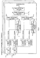
- FIG. 1 is a block diagram showing a configuration of the conventional base station apparatus.
- signals received through antennas 11-1 to 11-n are input to despreading sections 13-1 to 13-m after predetermined radio processing (such as down conversion, and analog to digital conversion) in RF sections 12-1 to 12-n provided corresponding to each antenna.
- predetermined radio processing such as down conversion, and analog to digital conversion
- the despreading sections 13-1 to 13-m perform despreading processing of signals arriving respectively through a first path to an m-th path. That is, the despreading sections 13-1 to 13-m perform the despreading processing according to receiving timing of the signals arriving through each path.
- signals passed through the first path hereinafter, called as "the path-1 signals” which have been received through the antennas 11-1 to 11-n are extracted by the despreading sections 13-1, respectively
- signals passed through the m-th path hereinafter, called as "the path-m signals" which have been received through the antennas 11-1 to 11-n are extracted by the despreading sections 13-m, respectively.
- N number of the path-1 signals are input to a direction-of-arrival estimation section 14-1 and an array receiving section 15-1
- N number of the path-m signals are input to a direction-of-arrival estimation section 14-m and an array receiving section 15-m.
- directions-of-arrival ⁇ 1 to ⁇ m of the path-1 to path-m signals are estimated.
- the estimated directions-of-arrival ⁇ 1 to ⁇ m are input to the array receiving sections 15-1 to 15-m, respectively.
- the path-1 signals received through each antenna are multiplied by a receiving weight generated by using the direction-of-arrival ⁇ 1 , and, then, the signals subjected to the multiplication are combined.
- the path-1 signals subjected to array combining are output from the array receiving section 15-1.
- the path-m signals subjected to array combining are output from the array receiving section 15-m.
- Channel fluctuations h 1 to h m are compensated by multiplication of the signals subjected to array combining by complex conjugates h 1 ' * to h m '* of channel estimation values h 1 ' to h m ', and, thereafter, RAKE combining of the signals is performed in a RAKE combining section 16.
- the signals subjected to the RAKE combining are demodulated in a demodulation section 17, and, thereby, demodulated data are obtained.
- the path-m signal received through an n-th antenna element may be expressed as the following formula (1).
- x nm ( t ) h m e j ⁇ ( n -1)sin ⁇ m ⁇ s ( t )
- h m represents a channel fluctuation on the path m; ⁇ m a direction-of-arrival of the path-m signal; and s(t) a desired signal.
- e j ⁇ (n-1)sin ⁇ m represents a phase rotation between each antenna element.
- interference components and noise components included in the received signal may be neglected.
- the path-1 signal received through the antenna 11-1 is expressed as the following formula (2); the path-1 signal received through the antenna 11-2 is expressed as the following formula (3); the path-2 signal received through the antenna 11-1 is expressed as the following formula (4); and the path-2 signal received through the antenna 11-2 is expressed as the following formula (5).
- the direction-of-arrival estimation section 14-1 estimates a direction-of-arrival ⁇ 1 , using the signal expressed in the above formula (2), and the signal expressed in the above formula (3).
- the direction-of-arrival estimation section 14-2 estimates a direction-of-arrival ⁇ 2 , using the signal expressed in the above formula (4), and the signal expressed in the above formula (5).
- the direction-of-arrival is estimated according to the following procedure. Here, it is assumed that a beamformer method is used as one example of methods for estimating the direction-of-arrival.
- a receiving weight vector W( ⁇ ) by which the signals received through each antenna are multiplied is assumed to be the following formula (6).
- W ( ⁇ ) [1, e - j ⁇ sin ⁇ , ⁇ , e - j (n-1) ⁇ sin ⁇ ]
- H represents a complex conjugate transposition
- E an average in the above formula (7).
- the signal expressed by the above formula (2), and the signal expressed by the above formula (3) are multiplied by receiving weight vectors expressed by the above formula (6), respectively, and, thereafter, angle spectrums are obtained by the above formula (7), with changing ⁇ . Then, a peak position on the angle spectrum is estimated as the direction-of-arrival ⁇ 1 of the path-1 signal. For example, when an angle spectrum for the path-1 signal is as shown in FIG. 2A, it is estimated that the direction-of-arrival ⁇ 1 is a direction of -40 degrees.
- the signal expressed by the above formula (4), and the signal expressed by the above formula (5) are multiplied by receiving weight vectors expressed by the above formula (6), respectively, and, thereafter, angle spectrums are obtained by the above formula (7), with changing ⁇ . Then, a peak position on the angle spectrum is estimated as the direction-of-arrival ⁇ 2 of the path-2 signal. For example, when the angle spectrum for the path-2 signal is as shown in FIG. 2B, it is estimated that the direction-of-arrival ⁇ 2 is a direction of 0 degrees.
- the apparatus size and the amount of operations are further increased, when the number of communication terminals (that is, a number of channels) that the base station apparatus can simultaneously communicate with.
- the apparatus size and the amount of operations in the base station apparatus have still more increasing tendency along with recent remarkable increase in the number of communication-terminal users.
- the object of the present invention is to provide a base station apparatus and a direction-of-arrival estimating method, by which path-diversity gain may be obtained, and, moreover, the apparatus sizemay be reduced by reducing the amount of operations at estimating a direction-of-arrival in the base station apparatus with an array antenna.
- the inventors of the present invention have noticed signal components required for estimating the direction-of-arrival, and have found that, under assumption that a signal input to a direction-of-arrival estimation section is a signal subjected to RAKE combining, directions-of-arrival for signals on a plurality of paths may be estimated at once, using one angle spectrum. Then, the present invention has been made.
- the present invention has a configuration in which, under a condition that a signal input to the direction-of-arrival estimation section is a signal including a plurality of components representing a phase rotation between each antenna element (that is, e j ⁇ (n-1)sin ⁇ m ), the directions-of-arrival for signals on a plurality of paths are estimated at once at one-time direction-of-arrival estimation processing.
- the apparatus size, and the amount of operations of the base station apparatus may be reduced.
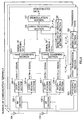
- FIG. 3 is a block diagram showing a configuration of a base station apparatus according to the embodiment 1 of the present invention.
- a plurality of antennas 101-1 to 101-n are arranged straight at intervals of the half wave-length of a carrier wave.
- signals received through the antennas 101-1 to 101-n are input to despreading sections 103-1 to 103-m after predetermined radio processing (such as down conversion, and analog to digital conversion) in RF sections 102-1 to 102-n provided corresponding to each antenna.
- predetermined radio processing such as down conversion, and analog to digital conversion
- the despreading sections 103-1 to 103-m perform despreading processing of the signals which arrive at the antennas 101-1 to 101-n through the paths 1 to m. That is, the despreading sections 103-1 to 103-m perform the despreading processing according to receiving timing of the signals arriving at the antennas 101-1 to 101-n through each path.
- the path-1 to path-m signals received through the antenna 101-1 are extracted by the despreading sections 103-1 to 103-m connected to the antenna 101-1, respectively.
- the path-1 to path-m signals received through the antenna 101-n are extracted by the despreading sections 103-1 to 103-m connected to the antenna 101-n, respectively.
- the path-1 to path-m signals received through the antenna 101-1 are input to a RAKE combining section 104-1, respectively, and the path-1 to path-m signals received through the antenna 101-n are input to a RAKE combining section 104-n, respectively.
- channel fluctuations h 1 to h m are compensated by multiplication of the path-1 to path-m signals received through the antenna 101-1 by complex conjugates h 1 '* to h m '* of channel estimation values h 1 ' to h m ', and, thereafter, RAKE combining of the signals is performed.
- the channel variations h 1 to h m are compensated by multiplication of the path-1 to path-m signals received through the antenna 101-n by the complex conjugates h 1 '* to h m '* of the channel estimation values h 1 ' to h m ', and, thereafter, RAKE combining of the signals is performed.
- the path-1 to the path-m signals are combined for each antenna, respectively, in the RAKE combining sections 104-1 to 104-n.
- the signals through each antenna subjected to RAKE combining are input to the direction-of-arrival estimation section 105, and the array receiving section 106.
- channel estimation method there are no special limitations in the channel estimation method.
- a method for channel estimation using known signals such as pilot symbols included in the received signals may be applied.
- the direction-of-arrival estimation section 105 estimates directions-of-arrival ⁇ 1 to ⁇ m of the path-1 to path-m signals at once, using the signals through each antenna subjected to the RAKE combining. That is, the direction-of-arrival estimation section 105 estimates directions-of-arrival for signals of a plurality of paths at once, using one angle spectrum. Operations of estimating the directions-of-arrival will be described later.
- the estimated directions-of-arrival ⁇ 1 to ⁇ m are input to the array receiving section 106.
- the signals through each antenna are multiplied by receiving weights generated by using the directions-of-arrival ⁇ 1 to ⁇ m , and, thereafter, the signals subjected to the multiplication are combined.
- a method for array combining will be described later.
- the signals subjected to the array combining are demodulated in a demodulation section 107, and, thereby, demodulated data are obtained.
- the path-m signal received through an n-th antenna element may be expressed as the above formula (1).
- the path-1 signal received through the antenna 101-1 may be expressed as the following formula (8); the path-2 signal received through the antenna 101-1 as the following formula (9); the path-1 signal received through the antenna 101-2 as the following formula (10); and the path-2 signal received through the antenna 101-2 as the following formula (11).
- the signals expressed by the above formulae (12), (13) are input to the direction-of-arrival estimation section 105, respectively.
- the direction-of-arrival estimation section 105 estimates, by one-time processing for direction-of-arrival estimation, the direction-of-arrival ⁇ 1 of the path-1 signal, and the direction-of-arrival ⁇ 2 of the path-2 signal at once, using the signals expressed by the above formulae (12), (13).
- the direction-of-arrival estimation section 105 estimates directions-of-arrival at once according to the following method, using the same method as that of the above conventional case (a beamformer method listed as one example).
- the signal expressed by the above formula (12), and the signal expressed by the above formula (13) are multiplied by receiving weight vectors expressed by the above formula (6), respectively, and, thereafter, angle spectrums are obtained by the above formula (7), with changing ⁇ .
- a first peak position is estimated as the direction-of-arrival ⁇ 1 of the path-1 signal
- a second peak position is estimated as the direction-of-arrival ⁇ 2 of the path-2 signal. That is, it is estimated from one angle spectrum that the direction-of-arrival ⁇ 1 is as a direction of -40 degrees, and the direction-of-arrival ⁇ 2 is as a direction of 0 degrees.
- two directions-of-arrival are estimated at once from one angle spectrum in the direction-of-arrival estimation section 105.
- the estimated directions-of-arrival ⁇ 1 , ⁇ 2 are output to the array receiving section 106.
- the signals expressed by the above formula (12), and by the above formula (13) are multiplied by a receiving weight generated by using the directions-of-arrival ⁇ 1 , ⁇ 2 , respectively, and, thereafter, the signals subjected to the multiplication are combined.
- the array receiving section 106 generates a receiving weight expressed by the following formula (14), using W( ⁇ 1 ) generated by substituting the direction-of-arrival ⁇ 1 into the above formula (6), and W( ⁇ 2 ) generated by substituting the direction-of-arrival ⁇ 2 into the above formula (6).
- the base station apparatus may strongly receive only a signal arriving from a direction of ⁇ 1 , and a signal arriving from a direction of ⁇ 2 .
- directions-of-arrival may be estimated in the direction-of-arrival estimation section, using signals representing a plurality of components representing a phase rotation between each antenna element (that is, e j ⁇ (n-1)sin ⁇ m ), as signals input to the direction-of-arrival estimation section are configured to be signals after RAKE combining. Accordingly, a plurality of directions-of-arrival may be estimated from one angle spectrum at once in the direction-of-arrival estimation section. Thereby, the amount of operations may be reduced.
- the base station apparatus is required to be provided with only one direction-of-arrival estimation section every communication terminal, as all the directions-of-arrival may be estimated from one angle spectrum in the direction-of-arrival estimation section. Thereby, reduction in the size of the base station apparatus may be realized.
- the direction-of-arrival estimation section is not required to be newly developed, and the conventional direction-of-arrival estimation section may be used as it is, as a plurality of directions-of-arrival may be estimated at once, using the same method as that of the conventional case. Accordingly, development cost may be suppressed when a base station apparatus with small apparatus size is developed.
- a number, which is equal to that of the antennas, of RAKE combining sections are required to be provided in the configuration shown in FIG. 3 when the configuration shown in FIG. 3, and the conventional one shown in FIG. 1 are compared. Accordingly, in the present embodiment, the number of the RAKE combining sections is increased in comparison with that of the conventional case.
- the amount of operations in the RAKE combining sections is remarkably small, comparing with that of matrix operations and so on required for estimating the directions-of-arrival. Accordingly, the apparatus size and the amount of operations may be reduced as the whole base station apparatus by reducing the number of direction-of-arrival estimation sections even if the number of the RAKE combining sections is increased.
- FIG. 5 is a block diagram showing a configuration of a base station apparatus according to the embodiment 2 of the present invention.
- the base station apparatus shown in FIG. 5 has a configuration in which a modulation section 301; an array transmission section 302; and a spreading section 303 are further provided in addition to sections shown in FIG. 3, and directions-of-arrival ⁇ 1 to ⁇ m which have been estimated in a direction-of-arrival estimation section 105 are configured to be used at signal transmission.
- FIG. 5 parts similar to those previously shown in FIG. 3 are denoted by the same reference numbers as those in FIG. 3, and detailed description will be eliminated.
- the modulation section 301 modulates transmission data for output to the array transmission section 302. And, a direction-of-arrival estimation section 105 outputs estimated directions-of-arrival ⁇ 1 to ⁇ m to the array transmission section 302.
- the array transmission section 302 generates transmission weights, using directions-of-arrival ⁇ 1 to ⁇ m which have been estimated in the direction-of-arrival estimation section 105. Then, the array transmission section 302 multiplies the signals output from the modulation section 301 by the transmission weights. Thereby, directivities for transmission signals are formed in the directions of angles of ⁇ 1 to ⁇ m . The transmission signals after multiplication by the transmission weights are output to the spreading section 303.
- the spreading section 303 spreads the output signals from the array transmission section 302, and outputs the signals after the spreading to a RF section 102.
- the RF section 102 performs predetermined radio processing (digital-to-analog conversion, up conversion, and so on) of the output signals from the spreading section 303, and, thereafter, transmits the signals to a communication terminal through antennas 101-1 to 101-n.
- directions-of-arrival ⁇ 1 to ⁇ m which have been estimated in one direction-of-arrival estimation section provided for every communication terminal, are used at transmitting signals.
- only one line connecting the direction-of-arrival estimation section and the array receiving section is required, though a plurality of the sections are required to be provided for every communication terminal. Accordingly, the size of the apparatus may be reduced, and, at the same time, the manufacturing cost may be suppressed in the base station apparatus which transmits signals under forming directivities by using an array antenna.
- signals which have arrived through each path have been combined, using RAKE combining.
- the combining method is not limited to the above one, and any combining methods, which can combine, for every antenna, signals which have arrived through each path, may be used in the present invention.
- the beamformer method has been listed as one example of a method for estimating directions-of-arrival in the above embodiments.
- the estimating method is not limited to the above one, and the present invention can be applied to a base station apparatus using an estimation method other than the beamformer method.
- the above embodiments have been described under assumption that a plurality of antennas are arranged straight at intervals of the half wave-length of a carrier wave.
- the configuration is not limited to the above one, and the present invention can be applied to all the base station apparatus which comprises a plurality of antennas, and forms directivities. That is, the present invention can be executed regardless of the arrangement of each antenna, as long as signals which have been combined for every antenna are signals including a plurality of components representing a phase rotation between antennas.
- the base station apparatus used for a communication system using a CDMA method as a multiplexing method has been described in the above embodiments.
- the multiplexing method is not limited to the above one, and the present invention can be applied to a base station apparatus used in a communication system using a multiplexing method such as a TDMA method, and an OFDM method.
- path diversity gain may be obtained in a base station apparatus provided with an array antenna, and, moreover, the apparatus size may be reduced and the amount of operations at estimating directions-of-arrival may be reduced.
Landscapes
- Engineering & Computer Science (AREA)
- Computer Networks & Wireless Communication (AREA)
- Signal Processing (AREA)
- Physics & Mathematics (AREA)
- General Physics & Mathematics (AREA)
- Radar, Positioning & Navigation (AREA)
- Remote Sensing (AREA)
- Radio Transmission System (AREA)
- Variable-Direction Aerials And Aerial Arrays (AREA)
- Mobile Radio Communication Systems (AREA)
Abstract
Signals including a plurality of components
representing a phase rotation between antenna elements
by combining signals, which have arrived through each
path of a first to an m-th paths, for every antenna are
generated in RAKE combining sections 104-1 to 104-n; one
angle spectrum is obtained in one direction-of-arrival
estimation section 105 provided in each communication
terminal, using the signals generated in the RAKE
combining sections 104-1 to 104-n; and a plurality of
directions-of-arrival are estimated en bloc by detecting
a plurality of peak positions on the angle spectrum.
Description
- The present invention relates to a base station apparatus provided with an array antenna, which is used in a digital radio communication system, and a direction-of-arrival estimating method.
- Interference by various kinds of signals causes deterioration in received quality of a signal which a base station apparatus receives. An array antenna has been known as a technology for controlling the interference, and for strongly receiving only a signal arriving from a desired direction. The array antenna comprises a plurality of antenna elements, and is an antenna for arbitrarily setting a directivity by adjusting the amplitudes and phases of signals received through each antenna element. By using the array antenna, only a signal arriving from a desired direction may be strongly received by adjusting a weighting coefficient (hereinafter, called as "weight") by which the received signal is multiplied, and by regulating the amplitudes and phases of the received signal.
- Moreover, there is a RAKE receiving technology as a technology for improving the received quality. By using the RAKE receiving, path diversity gain may be obtained by combining signals arriving through different paths from each other under a multipath environment on a time axis. Generally, even in a base station apparatus provided with the array antenna, the RAKE receiving is often used together.
- In this case, the base station apparatus estimates each direction-of-arrival for signals arriving through paths respectively, and receives signals through the array antenna forming directivities in the estimated directions. Hereinafter, a conventional base station apparatus performing the array receiving and the RAKE receiving together will be described.
- FIG. 1 is a block diagram showing a configuration of the conventional base station apparatus. In the base station apparatus, signals received through antennas 11-1 to 11-n are input to despreading sections 13-1 to 13-m after predetermined radio processing (such as down conversion, and analog to digital conversion) in RF sections 12-1 to 12-n provided corresponding to each antenna.
- The despreading sections 13-1 to 13-m perform despreading processing of signals arriving respectively through a first path to an m-th path. That is, the despreading sections 13-1 to 13-m perform the despreading processing according to receiving timing of the signals arriving through each path. Thereby, signals passed through the first path (hereinafter, called as "the path-1 signals") which have been received through the antennas 11-1 to 11-n are extracted by the despreading sections 13-1, respectively, and signals passed through the m-th path (hereinafter, called as "the path-m signals") which have been received through the antennas 11-1 to 11-n are extracted by the despreading sections 13-m, respectively. N number of the path-1 signals are input to a direction-of-arrival estimation section 14-1 and an array receiving section 15-1, and N number of the path-m signals are input to a direction-of-arrival estimation section 14-m and an array receiving section 15-m.
- In the direction-of-arrival estimation sections 14-1 to 14-m, directions-of-arrival 1 to m of the path-1 to path-m signals are estimated. The estimated directions-of-arrival 1 to m are input to the array receiving sections 15-1 to 15-m, respectively.
- In the array receiving section 15-1, the path-1 signals received through each antenna are multiplied by a receiving weight generated by using the direction-of-arrival 1, and, then, the signals subjected to the multiplication are combined. Thereby, the path-1 signals subjected to array combining are output from the array receiving section 15-1. Similarly, the path-m signals subjected to array combining are output from the array receiving section 15-m.
- Channel fluctuations h1 to hm are compensated by multiplication of the signals subjected to array combining by complex conjugates h1 '* to hm'* of channel estimation values h1' to hm', and, thereafter, RAKE combining of the signals is performed in a
RAKE combining section 16. The signals subjected to the RAKE combining are demodulated in ademodulation section 17, and, thereby, demodulated data are obtained. - Subsequently, operations for estimating a direction-of-arrival, which are executed in the above conventional base station apparatus, will be described. Here, it is assumed for easy description that received signals arrive through two paths of the
path 1 and thepath 2 , and an array antenna comprises two antenna elements of the antennas 11-1 and 11-2. In a word, description will be made under assumption of m=2 and n=2 in the block diagram shown in FIG. 1. Moreover, it is assumed that each antenna element is arranged straight at intervals of the half wave-length of a carrier wave. - Generally, the path-m signal received through an n-th antenna element may be expressed as the following formula (1).
- In the above formula (1), hm represents a channel fluctuation on the path m; m a direction-of-arrival of the path-m signal; and s(t) a desired signal.
- Moreover, ejπ(n-1)sinm represents a phase rotation between each antenna element. Here, it is assumed for easy description that interference components and noise components included in the received signal may be neglected.
- Accordingly, the path-1 signal received through the antenna 11-1 is expressed as the following formula (2); the path-1 signal received through the antenna 11-2 is expressed as the following formula (3); the path-2 signal received through the antenna 11-1 is expressed as the following formula (4); and the path-2 signal received through the antenna 11-2 is expressed as the following formula (5).
h h - The direction-of-arrival estimation section 14-1 estimates a direction-of-arrival 1, using the signal expressed in the above formula (2), and the signal expressed in the above formula (3). Similarly, the direction-of-arrival estimation section 14-2 estimates a direction-of-arrival 2, using the signal expressed in the above formula (4), and the signal expressed in the above formula (5). Specifically, the direction-of-arrival is estimated according to the following procedure. Here, it is assumed that a beamformer method is used as one example of methods for estimating the direction-of-arrival.
- In the beamformer method, a receiving weight vector W() by which the signals received through each antenna are multiplied is assumed to be the following formula (6).
- Then, directions-of-arrival for signals of each path are estimated by detecting peak positions of angle spectrums PBF(), which is represented by the following formula (7) using an auto-correlation matrix RXX of a received signal X.
- Here, H represents a complex conjugate transposition, and E an average in the above formula (7).
- That is, in the direction-of-arrival estimation section 14-1, the signal expressed by the above formula (2), and the signal expressed by the above formula (3) are multiplied by receiving weight vectors expressed by the above formula (6), respectively, and, thereafter, angle spectrums are obtained by the above formula (7), with changing . Then, a peak position on the angle spectrum is estimated as the direction-of-arrival 1 of the path-1 signal. For example, when an angle spectrum for the path-1 signal is as shown in FIG. 2A, it is estimated that the direction-of-arrival 1 is a direction of -40 degrees.
- Similarly, in the direction-of-arrival estimation section 14-2, the signal expressed by the above formula (4), and the signal expressed by the above formula (5) are multiplied by receiving weight vectors expressed by the above formula (6), respectively, and, thereafter, angle spectrums are obtained by the above formula (7), with changing . Then, a peak position on the angle spectrum is estimated as the direction-of-arrival 2 of the path-2 signal. For example, when the angle spectrum for the path-2 signal is as shown in FIG. 2B, it is estimated that the direction-of-arrival 2 is a direction of 0 degrees.
- However, as angle spectrums are obtained for each path, direction-of-arrival estimation sections for one same operation is required to be provided for each path in the conventional base station apparatus with the above configuration, there has been caused a problem that the apparatus size is increased. When m number of path signals are subjected to RAKE combining, it is required to provide m number of direction-of-arrival estimation sections for one same operation.
- Moreover, as operations as expressed in the above formula (6) and the above formula (7) are performed in order to obtain an angle spectrum, there has been a problem in the above conventional base station apparatus that the amount of operations is exponentially increased according to increase in the number of antenna elements and the number of target paths for the RAKE combining.
- Moreover, as the above configuration is provided for each communication terminal as shown in FIG. 1, the apparatus size and the amount of operations are further increased, when the number of communication terminals (that is, a number of channels) that the base station apparatus can simultaneously communicate with. The apparatus size and the amount of operations in the base station apparatus have still more increasing tendency along with recent remarkable increase in the number of communication-terminal users.
- The object of the present invention is to provide a base station apparatus and a direction-of-arrival estimating method, by which path-diversity gain may be obtained, and, moreover, the apparatus sizemay be reduced by reducing the amount of operations at estimating a direction-of-arrival in the base station apparatus with an array antenna.
- The inventors of the present invention have noticed signal components required for estimating the direction-of-arrival, and have found that, under assumption that a signal input to a direction-of-arrival estimation section is a signal subjected to RAKE combining, directions-of-arrival for signals on a plurality of paths may be estimated at once, using one angle spectrum. Then, the present invention has been made.
- Now, the present invention has a configuration in which, under a condition that a signal input to the direction-of-arrival estimation section is a signal including a plurality of components representing a phase rotation between each antenna element (that is, ejπ(n-1)sin m), the directions-of-arrival for signals on a plurality of paths are estimated at once at one-time direction-of-arrival estimation processing. Thereby, the apparatus size, and the amount of operations of the base station apparatus may be reduced.
-
- FIG. 1 is a block diagram showing a configuration of a conventional base station apparatus;
- FIG. 2A shows one example of an angle spectrum which is obtained in a direction-of-arrival estimation section in the conventional base station apparatus;
- FIG. 2B shows another example of the angle spectrum which is obtained in the direction-of-arrival estimation section in the conventional base station apparatus;
- FIG. 3 is a block diagram showing a configuration
of a base station apparatus according to an
embodiment 1 of the present invention; - FIG. 4 shows one example of an angle spectrum which
is obtained in a direction-of-arrival estimation section
in the base station apparatus according to the
embodiment 1 of the present invention; and - FIG. 5 is a block diagram showing a configuration
of a base station apparatus according to an
embodiment 2 of the present invention. -
- Hereinafter, embodiments of the present invention will be described in detail, referring to drawings.
- FIG. 3 is a block diagram showing a configuration of a base station apparatus according to the
embodiment 1 of the present invention. Here, it is assumed in the base station apparatus that a plurality of antennas 101-1 to 101-n are arranged straight at intervals of the half wave-length of a carrier wave. - In the base station apparatus shown in FIG. 3, signals received through the antennas 101-1 to 101-n are input to despreading sections 103-1 to 103-m after predetermined radio processing (such as down conversion, and analog to digital conversion) in RF sections 102-1 to 102-n provided corresponding to each antenna.
- The despreading sections 103-1 to 103-m perform despreading processing of the signals which arrive at the antennas 101-1 to 101-n through the
paths 1 to m. That is, the despreading sections 103-1 to 103-m perform the despreading processing according to receiving timing of the signals arriving at the antennas 101-1 to 101-n through each path. - Thereby, the path-1 to path-m signals received through the antenna 101-1 are extracted by the despreading sections 103-1 to 103-m connected to the antenna 101-1, respectively. Similarly, the path-1 to path-m signals received through the antenna 101-n are extracted by the despreading sections 103-1 to 103-m connected to the antenna 101-n, respectively. The path-1 to path-m signals received through the antenna 101-1 are input to a RAKE combining section 104-1, respectively, and the path-1 to path-m signals received through the antenna 101-n are input to a RAKE combining section 104-n, respectively.
- In the RAKE combining section 104-1, channel fluctuations h1 to hm are compensated by multiplication of the path-1 to path-m signals received through the antenna 101-1 by complex conjugates h1'* to hm'* of channel estimation values h1' to hm', and, thereafter, RAKE combining of the signals is performed. Similarly, in the RAKE combining section 104-n, the channel variations h1 to hm are compensated by multiplication of the path-1 to path-m signals received through the antenna 101-n by the complex conjugates h1'* to hm'* of the channel estimation values h1' to hm', and, thereafter, RAKE combining of the signals is performed. That is, the path-1 to the path-m signals are combined for each antenna, respectively, in the RAKE combining sections 104-1 to 104-n. The signals through each antenna subjected to RAKE combining are input to the direction-of-
arrival estimation section 105, and thearray receiving section 106. - Here, there are no special limitations in the channel estimation method. For example, a method for channel estimation using known signals such as pilot symbols included in the received signals may be applied.
- The direction-of-
arrival estimation section 105 estimates directions-of-arrival 1 to m of the path-1 to path-m signals at once, using the signals through each antenna subjected to the RAKE combining. That is, the direction-of-arrival estimation section 105 estimates directions-of-arrival for signals of a plurality of paths at once, using one angle spectrum. Operations of estimating the directions-of-arrival will be described later. The estimated directions-of-arrival 1 to m are input to thearray receiving section 106. - In the
array receiving section 106, the signals through each antenna are multiplied by receiving weights generated by using the directions-of-arrival 1 to m, and, thereafter, the signals subjected to the multiplication are combined. A method for array combining will be described later. The signals subjected to the array combining are demodulated in ademodulation section 107, and, thereby, demodulated data are obtained. - Then, operations for estimating directions-of-arrival and array combining in the base station apparatus with the above configuration will be described. Here, it is assumed for easy description that the received signals arrive through two paths of the
path 1 and thepath 2, and the array antenna comprises two antenna elements of the antennas 101-1 and 101-2. That is, description will be made under assumption of m=2 and n=2 in the block diagram shown in FIG. 3. - As described above, the path-m signal received through an n-th antenna element may be expressed as the above formula (1). Accordingly, the path-1 signal received through the antenna 101-1 may be expressed as the following formula (8); the path-2 signal received through the antenna 101-1 as the following formula (9); the path-1 signal received through the antenna 101-2 as the following formula (10); and the path-2 signal received through the antenna 101-2 as the following formula (11).
h h - Here, it is assumed for easy description that interference components and noise components included in the received signals may be neglected.
- Then, the signals expressed by the above formulae (8), (9) are input to the RAKE combining section 104-1; and the signals expressed by the above formulae (10), (11) are input to the RAKE combining section 104-2.
- The signals expressed by the above formulae (8), (9) are multiplied by the complex conjugates h1'*, h2'* of the channel estimation values h1', h2', respectively, and, thereafter, RAKE combining of the signals is performed. Accordingly, the signal obtained after RAKE combining of the signal received through the antenna 101-1 is expressed by the following formula (12).
- And, the signals expressed by the above formulae (10), (11) are multiplied by the complex conjugates h1'*, h2'* of the channel estimation values h1', h2', and, thereafter, RAKE combining of the signals is performed. Accordingly, the signal obtained after the RAKE combining of the signals received through the antenna 101-2 is expressed by the following formula (13).
- The signals expressed by the above formulae (12), (13) are input to the direction-of-
arrival estimation section 105, respectively. Subsequently, the direction-of-arrival estimation section 105 estimates, by one-time processing for direction-of-arrival estimation, the direction-of-arrival 1 of the path-1 signal, and the direction-of-arrival 2 of the path-2 signal at once, using the signals expressed by the above formulae (12), (13). Specifically, the direction-of-arrival estimation section 105 estimates directions-of-arrival at once according to the following method, using the same method as that of the above conventional case (a beamformer method listed as one example). - That is, in the direction-of-
arrival estimation section 105, the signal expressed by the above formula (12), and the signal expressed by the above formula (13) are multiplied by receiving weight vectors expressed by the above formula (6), respectively, and, thereafter, angle spectrums are obtained by the above formula (7), with changing . - Here, noticing the signal expressed by the above formula (13), which has been subjected to RAKE combining in the RAKE combining section 104-2, a plurality of components representing a phase rotation between the antenna elements are included in the signal expressed by the above formula (13). That is, both a phase rotation ejπsin1 expressed by using the direction-of-arrival 1, and a phase rotation ejπsin2 expressed by using the direction-of-arrival 2 are included in the signal expressed by the above formula (13).
- Accordingly, two peaks appear on one angle spectrum, as shown in FIG. 4, when the angle spectrum is obtained by using signals expressed by the above formulae (12), (13) in the direction-of-
arrival estimation section 105. In a word, a first peak appears at a position of 1, and a second peak appears at a position of 2. - Then, in the direction-of-
arrival estimation section 105, a first peak position is estimated as the direction-of-arrival 1 of the path-1 signal, and a second peak position is estimated as the direction-of-arrival 2 of the path-2 signal. That is, it is estimated from one angle spectrum that the direction-of-arrival 1 is as a direction of -40 degrees, and the direction-of-arrival 2 is as a direction of 0 degrees. Thus, two directions-of-arrival are estimated at once from one angle spectrum in the direction-of-arrival estimation section 105. The estimated directions-of-arrival 1, 2 are output to thearray receiving section 106. - In the
array receiving section 106, the signals expressed by the above formula (12), and by the above formula (13) are multiplied by a receiving weight generated by using the directions-of-arrival 1, 2, respectively, and, thereafter, the signals subjected to the multiplication are combined. - For example, the
array receiving section 106 generates a receiving weight expressed by the following formula (14), using W(1) generated by substituting the direction-of-arrival 1 into the above formula (6), and W( 2) generated by substituting the direction-of-arrival 2 into the above formula (6). - Then, the signals expressed by the above formula (12), and by the above formula (13) are multiplied by the receiving weight expressed by the above formula (14), respectively, and, thereafter, the signals subjected to the multiplication are combined. Thereby, the base station apparatus may strongly receive only a signal arriving from a direction of 1, and a signal arriving from a direction of 2.
- Thus, according to the present embodiment, directions-of-arrival may be estimated in the direction-of-arrival estimation section, using signals representing a plurality of components representing a phase rotation between each antenna element (that is, ej π (n-1)sin m), as signals input to the direction-of-arrival estimation section are configured to be signals after RAKE combining. Accordingly, a plurality of directions-of-arrival may be estimated from one angle spectrum at once in the direction-of-arrival estimation section. Thereby, the amount of operations may be reduced.
- Moreover, according to the present embodiment, the base station apparatus is required to be provided with only one direction-of-arrival estimation section every communication terminal, as all the directions-of-arrival may be estimated from one angle spectrum in the direction-of-arrival estimation section. Thereby, reduction in the size of the base station apparatus may be realized.
- In addition, a number, which is equal to that of the paths, of lines connecting the direction-of-arrival estimation section and the array receiving section have been required to be provided in the above conventional base station apparatus, as a number, which is equal to that of the paths, of the direction-of-arrival estimation sections have been required to be provided. However, according to the present embodiment, only one line connecting the direction-of-arrival estimation section and the array receiving section is required, as only one direction-of-arrival section is required to be provided for every communication terminal. Accordingly, the size of the apparatus may be further reduced, and, at the same time, the manufacturing cost may be also suppressed.
- And, according to the present embodiment, the direction-of-arrival estimation section is not required to be newly developed, and the conventional direction-of-arrival estimation section may be used as it is, as a plurality of directions-of-arrival may be estimated at once, using the same method as that of the conventional case. Accordingly, development cost may be suppressed when a base station apparatus with small apparatus size is developed.
- Here, a number, which is equal to that of the antennas, of RAKE combining sections are required to be provided in the configuration shown in FIG. 3 when the configuration shown in FIG. 3, and the conventional one shown in FIG. 1 are compared. Accordingly, in the present embodiment, the number of the RAKE combining sections is increased in comparison with that of the conventional case. However, the amount of operations in the RAKE combining sections is remarkably small, comparing with that of matrix operations and so on required for estimating the directions-of-arrival. Accordingly, the apparatus size and the amount of operations may be reduced as the whole base station apparatus by reducing the number of direction-of-arrival estimation sections even if the number of the RAKE combining sections is increased.
- FIG. 5 is a block diagram showing a configuration of a base station apparatus according to the
embodiment 2 of the present invention. The base station apparatus shown in FIG. 5 has a configuration in which amodulation section 301; anarray transmission section 302; and a spreadingsection 303 are further provided in addition to sections shown in FIG. 3, and directions-of-arrival 1 to m which have been estimated in a direction-of-arrival estimation section 105 are configured to be used at signal transmission. Here, in FIG. 5, parts similar to those previously shown in FIG. 3 are denoted by the same reference numbers as those in FIG. 3, and detailed description will be eliminated. - In the base station apparatus shown in FIG. 5, the
modulation section 301 modulates transmission data for output to thearray transmission section 302. And, a direction-of-arrival estimation section 105 outputs estimated directions-of-arrival 1 to m to thearray transmission section 302. - The
array transmission section 302 generates transmission weights, using directions-of-arrival 1 to m which have been estimated in the direction-of-arrival estimation section 105. Then, thearray transmission section 302 multiplies the signals output from themodulation section 301 by the transmission weights. Thereby, directivities for transmission signals are formed in the directions of angles of 1 to m. The transmission signals after multiplication by the transmission weights are output to the spreadingsection 303. - The spreading
section 303 spreads the output signals from thearray transmission section 302, and outputs the signals after the spreading to aRF section 102. TheRF section 102 performs predetermined radio processing (digital-to-analog conversion, up conversion, and so on) of the output signals from the spreadingsection 303, and, thereafter, transmits the signals to a communication terminal through antennas 101-1 to 101-n. - As described above, according to the present embodiment, directions-of-arrival 1 to m, which have been estimated in one direction-of-arrival estimation section provided for every communication terminal, are used at transmitting signals. Thereby, according to the present embodiment, only one line connecting the direction-of-arrival estimation section and the array receiving section is required, though a plurality of the sections are required to be provided for every communication terminal. Accordingly, the size of the apparatus may be reduced, and, at the same time, the manufacturing cost may be suppressed in the base station apparatus which transmits signals under forming directivities by using an array antenna.
- Here, in the above embodiments, signals which have arrived through each path have been combined, using RAKE combining. However, the combining method is not limited to the above one, and any combining methods, which can combine, for every antenna, signals which have arrived through each path, may be used in the present invention.
- Moreover, the beamformer method has been listed as one example of a method for estimating directions-of-arrival in the above embodiments. However, the estimating method is not limited to the above one, and the present invention can be applied to a base station apparatus using an estimation method other than the beamformer method.
- In addition, the above embodiments have been described under assumption that a plurality of antennas are arranged straight at intervals of the half wave-length of a carrier wave. However, the configuration is not limited to the above one, and the present invention can be applied to all the base station apparatus which comprises a plurality of antennas, and forms directivities. That is, the present invention can be executed regardless of the arrangement of each antenna, as long as signals which have been combined for every antenna are signals including a plurality of components representing a phase rotation between antennas.
- Furthermore, the base station apparatus used for a communication system using a CDMA method as a multiplexing method has been described in the above embodiments. However, the multiplexing method is not limited to the above one, and the present invention can be applied to a base station apparatus used in a communication system using a multiplexing method such as a TDMA method, and an OFDM method.
- As described above, according to the present invention, path diversity gain may be obtained in a base station apparatus provided with an array antenna, and, moreover, the apparatus size may be reduced and the amount of operations at estimating directions-of-arrival may be reduced.
- The present description is based upon claims from the prior Japanese Patent Application 2000 - 272543, filed on September 8, 2000. The entire contents are incorporated herein by reference.
Claims (6)
- A base station apparatus comprising:a receiver for receiving same signals, which have arrived from a plurality of directions through different paths, using an array antenna having a plurality of antenna elements;a first combiner for combining a plurality of said same signals, which have been received through each antenna element, for every antenna element; anda direction-of-arrival estimator for estimating said plurality of directions at once, using signals combined by said first combiner.
- A base station apparatus according to claim 1, wherein
signals combined by said first combiner are signals including a plurality of components representing a phase rotation between said antenna elements; - A base station apparatus according to claim 1, wherein
said direction-of-arrival estimator obtains one angle spectrum, using said signals combined by said first combiner, and
estimates a plurality of directions at once by detecting a plurality of peak positions on said angle spectrum. - A base station apparatus according to claim 1, further comprising:a second combiner which multiplies signals combined by said first combiner by receiving weights generated by using directions estimated by said direction-of-arrival estimator, and, thereafter, combines signals after multiplication, whereindirectivity is formed in directions estimated by said direction-of-arrival estimator, and signals are received.
- A base station apparatus according to claim 1, further comprising:a transmitter which multiplies transmission signal by transmission weight generated by using directions estimated by said direction-of-arrival estimator, and, thereafter, transmits signal after multiplication, whereindirectivity is formed in directions estimated by said direction-of-arrival estimator, and the signal is transmitted.
- A direction-of-arrival estimating method having the following steps:a step of estimating said plurality of directions at once by detecting a plurality of peak positions of said angle spectrum.a step of receiving same signals, which have arrived from a plurality of directions through different paths, using an array antenna having a plurality of antenna elements;a step of generating signals including a plurality of components representing a phase rotation between antenna elements by combining a plurality of said same signals which have been received through each antenna element;a step of obtaining one angle spectrum, using said generated signals; and
Applications Claiming Priority (3)
| Application Number | Priority Date | Filing Date | Title |
|---|---|---|---|
| JP2000272543A JP2002084217A (en) | 2000-09-08 | 2000-09-08 | Base station apparatus and arrival direction estimation method |
| JP2000272543 | 2000-09-08 | ||
| PCT/JP2001/007517 WO2002021723A1 (en) | 2000-09-08 | 2001-08-31 | Base station device and arrival direction deducing method |
Publications (1)
| Publication Number | Publication Date |
|---|---|
| EP1235362A1 true EP1235362A1 (en) | 2002-08-28 |
Family
ID=18758638
Family Applications (1)
| Application Number | Title | Priority Date | Filing Date |
|---|---|---|---|
| EP20010961239 Withdrawn EP1235362A1 (en) | 2000-09-08 | 2001-08-31 | Base station device and arrival direction deducing method |
Country Status (6)
| Country | Link |
|---|---|
| US (1) | US7095984B2 (en) |
| EP (1) | EP1235362A1 (en) |
| JP (1) | JP2002084217A (en) |
| CN (1) | CN1153375C (en) |
| AU (1) | AU2001282567A1 (en) |
| WO (1) | WO2002021723A1 (en) |
Cited By (1)
| Publication number | Priority date | Publication date | Assignee | Title |
|---|---|---|---|---|
| EP1883176A4 (en) * | 2005-05-12 | 2009-12-16 | Shanghai Ultimate Power Comm | A direction of arrival estimation method for terminals of the same frequency cells |
Families Citing this family (7)
| Publication number | Priority date | Publication date | Assignee | Title |
|---|---|---|---|---|
| JP3895228B2 (en) | 2002-05-07 | 2007-03-22 | 松下電器産業株式会社 | Wireless communication apparatus and direction of arrival estimation method |
| JP3796212B2 (en) * | 2002-11-20 | 2006-07-12 | 松下電器産業株式会社 | Base station apparatus and transmission allocation control method |
| JP2004297665A (en) * | 2003-03-28 | 2004-10-21 | Kyocera Corp | Wireless receiving device, communication control method |
| CN100444531C (en) * | 2003-03-31 | 2008-12-17 | 富士通株式会社 | receiving device |
| JP4299083B2 (en) * | 2003-09-09 | 2009-07-22 | 株式会社エヌ・ティ・ティ・ドコモ | Wireless communication apparatus and wireless communication method |
| JP4555656B2 (en) * | 2003-10-16 | 2010-10-06 | 日本放送協会 | Radio wave arrival direction estimation device |
| SG133423A1 (en) * | 2005-12-14 | 2007-07-30 | Oki Techno Ct Singapore Pte | A method, apraratus and receiver for demapping dual carrier modulated cofdm signals |
Family Cites Families (22)
| Publication number | Priority date | Publication date | Assignee | Title |
|---|---|---|---|---|
| EP0846378B1 (en) * | 1995-08-22 | 1999-10-06 | Thomson-Csf | Method and device for spatial multiplexing-demultiplexing of radio signals for an sdma mobile radio system |
| JP3204111B2 (en) * | 1996-08-28 | 2001-09-04 | 松下電器産業株式会社 | Directivity control antenna device |
| US6122260A (en) * | 1996-12-16 | 2000-09-19 | Civil Telecommunications, Inc. | Smart antenna CDMA wireless communication system |
| JPH1141157A (en) * | 1997-07-23 | 1999-02-12 | Kokusai Electric Co Ltd | Receiver |
| DE19753932A1 (en) * | 1997-12-05 | 1999-06-10 | Cit Alcatel | Method for determining the direction of reception by means of a group antenna, base station and radio system |
| JP3233088B2 (en) * | 1998-01-22 | 2001-11-26 | 松下電器産業株式会社 | Directivity control antenna device |
| US5936575A (en) * | 1998-02-13 | 1999-08-10 | Science And Applied Technology, Inc. | Apparatus and method for determining angles-of-arrival and polarization of incoming RF signals |
| JP3716398B2 (en) | 1998-03-05 | 2005-11-16 | 富士通株式会社 | Direction-of-arrival estimation method using array antenna and DS-CDMA receiver using the method |
| JP3510784B2 (en) | 1998-03-12 | 2004-03-29 | シャープ株式会社 | Video recording and playback methods |
| JPH11266180A (en) * | 1998-03-18 | 1999-09-28 | Fujitsu Ltd | Array antenna system for wireless base station |
| JP3406831B2 (en) * | 1998-03-19 | 2003-05-19 | 富士通株式会社 | Array antenna system for wireless base station |
| JP3465739B2 (en) * | 1998-04-07 | 2003-11-10 | 日本電気株式会社 | CDMA adaptive antenna receiving apparatus and communication system |
| JP2000022611A (en) * | 1998-06-29 | 2000-01-21 | Matsushita Electric Ind Co Ltd | Transmission power control method and wireless communication device |
| EP0975100A1 (en) * | 1998-07-23 | 2000-01-26 | Siemens Aktiengesellschaft | Receiver and method of recovering data from radio signals |
| JP2000059278A (en) | 1998-08-03 | 2000-02-25 | Matsushita Electric Ind Co Ltd | Wireless communication device |
| US6311043B1 (en) * | 1998-10-27 | 2001-10-30 | Siemens Aktiengesellschaft | Method and measurement configuration for measuring the characteristics of radio channels |
| JP2000147083A (en) | 1998-11-06 | 2000-05-26 | Ntt Mobil Communication Network Inc | Arrival angle measuring method and angle of arrival measuring instrument |
| JP3920483B2 (en) * | 1998-12-28 | 2007-05-30 | 株式会社東芝 | Radio wave arrival direction estimation method and antenna apparatus |
| US6075484A (en) * | 1999-05-03 | 2000-06-13 | Motorola, Inc. | Method and apparatus for robust estimation of directions of arrival for antenna arrays |
| US6333713B1 (en) * | 1999-08-24 | 2001-12-25 | Matsushita Electric Industrial Co., Ltd. | Direction estimating apparatus, directivity controlling antenna apparatus, and direction estimating method |
| JP2002237766A (en) * | 2001-02-08 | 2002-08-23 | Nec Corp | Adaptive antenna receiving device |
| FR2824145B1 (en) * | 2001-04-27 | 2005-04-15 | Thomson Csf | METHOD AND DEVICE FOR SPATIO-TEMPORAL ESTIMATION OF ONE OR MORE TRANSMITTERS |
-
2000
- 2000-09-08 JP JP2000272543A patent/JP2002084217A/en not_active Withdrawn
-
2001
- 2001-08-31 EP EP20010961239 patent/EP1235362A1/en not_active Withdrawn
- 2001-08-31 CN CNB018025838A patent/CN1153375C/en not_active Expired - Fee Related
- 2001-08-31 WO PCT/JP2001/007517 patent/WO2002021723A1/en not_active Ceased
- 2001-08-31 US US10/129,378 patent/US7095984B2/en not_active Expired - Fee Related
- 2001-08-31 AU AU2001282567A patent/AU2001282567A1/en not_active Abandoned
Non-Patent Citations (1)
| Title |
|---|
| See references of WO0221723A1 * |
Cited By (2)
| Publication number | Priority date | Publication date | Assignee | Title |
|---|---|---|---|---|
| EP1883176A4 (en) * | 2005-05-12 | 2009-12-16 | Shanghai Ultimate Power Comm | A direction of arrival estimation method for terminals of the same frequency cells |
| US8054785B2 (en) | 2005-05-12 | 2011-11-08 | Shanghai Ultimate Power Communications Technology Co., Ltd. | Method for estimating direction-of-arrival of terminal in multiple co-frequency cells |
Also Published As
| Publication number | Publication date |
|---|---|
| CN1153375C (en) | 2004-06-09 |
| JP2002084217A (en) | 2002-03-22 |
| US7095984B2 (en) | 2006-08-22 |
| CN1389030A (en) | 2003-01-01 |
| US20020183007A1 (en) | 2002-12-05 |
| WO2002021723A1 (en) | 2002-03-14 |
| AU2001282567A1 (en) | 2002-03-22 |
Similar Documents
| Publication | Publication Date | Title |
|---|---|---|
| US7099630B2 (en) | Beam forming method | |
| US7096041B2 (en) | Beam forming method | |
| EP1361679B1 (en) | Radio communication device and arrival direction estimation method | |
| US6771988B2 (en) | Radio communication apparatus using adaptive antenna | |
| AU2001296598B2 (en) | Method and apparatus for estimating downlink beamforming weights in a communications system | |
| US7747225B2 (en) | Mobile assisted downlink beamforming with antenna weight feedback | |
| US7342535B2 (en) | Beam-forming apparatus and method using a spatial interpolation based on regular spatial sampling | |
| EP1654891B1 (en) | Weight generation method for multi-antenna communication systems utilizing rf-based and baseband signal weighting and combining | |
| US8559402B2 (en) | Method and system for channel estimation in a spatial multiplexing MIMO system | |
| US7760814B2 (en) | Indoor radio transmission method for parallel radio transmission of digital data substreams and a mobile radio transmission system | |
| US6470192B1 (en) | Method of an apparatus for beam reduction and combining in a radio communications system | |
| JP4107494B2 (en) | Wireless communication system | |
| US20030128677A1 (en) | Method and system for transmitting data, with transmission antenna diversity | |
| EP1361678A2 (en) | Path search circuit, radio receiver and radio transmitter, utilizing a directional beam | |
| EP1345337A2 (en) | Adaptive antenna base station apparatus with direction of arrival estimation | |
| US20150124713A1 (en) | Methods Circuits Systems and Associated Computer Executable Code for Performing Beamforming Based Wireless Communication | |
| US20070009016A1 (en) | Radio communication system, radio communication method, radio transmitter and radio receiver | |
| EP1133072A1 (en) | Communication terminal device and channel estimating method | |
| CN101375517B (en) | Apparatus and method for controlling dynamic range of weight vectors according to combining methods in a mobile station equipped with multiple antennas in high rate packet data system using code division multiple access scheme | |
| EP1248386A1 (en) | Base station device | |
| EP1235362A1 (en) | Base station device and arrival direction deducing method | |
| US7319822B2 (en) | System and method of space-time equalization to mitigate effects of fading and scintillation for wireless communication | |
| US7418067B1 (en) | Processing diversity signals at a mobile device using phase adjustments | |
| JP4001880B2 (en) | Spatial multiplex transmission equipment | |
| JP4430060B2 (en) | Wireless communication apparatus and method |
Legal Events
| Date | Code | Title | Description |
|---|---|---|---|
| PUAI | Public reference made under article 153(3) epc to a published international application that has entered the european phase |
Free format text: ORIGINAL CODE: 0009012 |
|
| 17P | Request for examination filed |
Effective date: 20020506 |
|
| AK | Designated contracting states |
Kind code of ref document: A1 Designated state(s): AT BE CH CY DE DK ES FI FR GB GR IE IT LI LU MC NL PT SE TR |
|
| AX | Request for extension of the european patent |
Free format text: AL;LT;LV;MK;RO;SI |
|
| RIN1 | Information on inventor provided before grant (corrected) |
Inventor name: HOSHINO, MASAYUKI |
|
| RBV | Designated contracting states (corrected) |
Designated state(s): AT BE CH DE FR GB LI |
|
| STAA | Information on the status of an ep patent application or granted ep patent |
Free format text: STATUS: THE APPLICATION HAS BEEN WITHDRAWN |
|
| 18W | Application withdrawn |
Effective date: 20060628 |