EP1235333A2 - Soft start circuit for switching power supply - Google Patents
Soft start circuit for switching power supply Download PDFInfo
- Publication number
- EP1235333A2 EP1235333A2 EP01119453A EP01119453A EP1235333A2 EP 1235333 A2 EP1235333 A2 EP 1235333A2 EP 01119453 A EP01119453 A EP 01119453A EP 01119453 A EP01119453 A EP 01119453A EP 1235333 A2 EP1235333 A2 EP 1235333A2
- Authority
- EP
- European Patent Office
- Prior art keywords
- circuit
- power source
- soft
- switching power
- triangular wave
- Prior art date
- Legal status (The legal status is an assumption and is not a legal conclusion. Google has not performed a legal analysis and makes no representation as to the accuracy of the status listed.)
- Withdrawn
Links
- 239000003990 capacitor Substances 0.000 claims description 24
- 230000010354 integration Effects 0.000 claims description 2
- 238000000034 method Methods 0.000 description 12
- 238000010586 diagram Methods 0.000 description 11
- 230000010355 oscillation Effects 0.000 description 6
- 238000010276 construction Methods 0.000 description 3
- 230000000694 effects Effects 0.000 description 3
- 230000003247 decreasing effect Effects 0.000 description 2
- 101150053844 APP1 gene Proteins 0.000 description 1
- 241001362574 Decodes Species 0.000 description 1
- 101100189105 Homo sapiens PABPC4 gene Proteins 0.000 description 1
- 102100039424 Polyadenylate-binding protein 4 Human genes 0.000 description 1
- 230000007423 decrease Effects 0.000 description 1
- 238000007599 discharging Methods 0.000 description 1
- 230000001360 synchronised effect Effects 0.000 description 1
Images




Classifications
-
- H—ELECTRICITY
- H02—GENERATION; CONVERSION OR DISTRIBUTION OF ELECTRIC POWER
- H02M—APPARATUS FOR CONVERSION BETWEEN AC AND AC, BETWEEN AC AND DC, OR BETWEEN DC AND DC, AND FOR USE WITH MAINS OR SIMILAR POWER SUPPLY SYSTEMS; CONVERSION OF DC OR AC INPUT POWER INTO SURGE OUTPUT POWER; CONTROL OR REGULATION THEREOF
- H02M3/00—Conversion of DC power input into DC power output
- H02M3/22—Conversion of DC power input into DC power output with intermediate conversion into AC
- H02M3/24—Conversion of DC power input into DC power output with intermediate conversion into AC by static converters
- H02M3/28—Conversion of DC power input into DC power output with intermediate conversion into AC by static converters using discharge tubes with control electrode or semiconductor devices with control electrode to produce the intermediate AC
- H02M3/325—Conversion of DC power input into DC power output with intermediate conversion into AC by static converters using discharge tubes with control electrode or semiconductor devices with control electrode to produce the intermediate AC using devices of a triode or a transistor type requiring continuous application of a control signal
- H02M3/335—Conversion of DC power input into DC power output with intermediate conversion into AC by static converters using discharge tubes with control electrode or semiconductor devices with control electrode to produce the intermediate AC using devices of a triode or a transistor type requiring continuous application of a control signal using semiconductor devices only
-
- H—ELECTRICITY
- H02—GENERATION; CONVERSION OR DISTRIBUTION OF ELECTRIC POWER
- H02M—APPARATUS FOR CONVERSION BETWEEN AC AND AC, BETWEEN AC AND DC, OR BETWEEN DC AND DC, AND FOR USE WITH MAINS OR SIMILAR POWER SUPPLY SYSTEMS; CONVERSION OF DC OR AC INPUT POWER INTO SURGE OUTPUT POWER; CONTROL OR REGULATION THEREOF
- H02M1/00—Details of apparatus for conversion
- H02M1/36—Means for starting or stopping converters
-
- Y—GENERAL TAGGING OF NEW TECHNOLOGICAL DEVELOPMENTS; GENERAL TAGGING OF CROSS-SECTIONAL TECHNOLOGIES SPANNING OVER SEVERAL SECTIONS OF THE IPC; TECHNICAL SUBJECTS COVERED BY FORMER USPC CROSS-REFERENCE ART COLLECTIONS [XRACs] AND DIGESTS
- Y10—TECHNICAL SUBJECTS COVERED BY FORMER USPC
- Y10S—TECHNICAL SUBJECTS COVERED BY FORMER USPC CROSS-REFERENCE ART COLLECTIONS [XRACs] AND DIGESTS
- Y10S323/00—Electricity: power supply or regulation systems
- Y10S323/901—Starting circuits
Definitions
- the present invention relates to a soft-start circuit for a switching power source, and particularly to a soft-start circuit suitable for being implemented in a power source LSI chip.
- the soft-start circuit for the switching power source is a circuit for preventing occurrence of an overshoot (a rush current flowing through a main SW) at starting the switching power source by gradually opening a PWM pulse width from a minimum pulse width to slowly increasing a DC converted output of the power source.
- an external CR circuit or a circuit composed of a constant current source and an external capacitor is added to the switching power source, and the soft-start time period is determined by a time constant of the CR circuit or an integrating time of the capacitor.
- the capacitor can not be implemented in the power source LSI because a large capacitor of several tens nF to several ⁇ F is necessary to obtain the soft-start time period of several ms to several tens ms.
- the second or the third method uses a mainly digital circuit structure suitable for LSI, the digital circuit can be implemented in the LSI.
- the digital circuit is large in circuit scale and soft-started (or initialized) by microcomputer control, it is necessary to start up a power source of the microcomputer before starting the controlled circuit (the power source circuit). Therefore, the second or the third method has a problem in that the method does not fit to general-purpose switching power sources which do not require microcomputer control.
- a feature of a soft-start circuit of a switching power source in accordance with the present invention is that in the switching power source comprising a triangular wave generating circuit and an error amplifier and a PWM comparator, in normal time PWM pulses being obtained by comparing an output amplitude of triangular wave of the triangular wave generating circuit with an output voltage of the error amplifier as a reference voltage using the PWM comparator, the soft-start circuit of the switching power source comprises a soft-start reference value setting part composed of a group of resistance networks and a group of switches using the same means as an upper-and-lower limit setting part, composed of networks and switches, for setting an upper and a lower limits of the amplitude of triangular wave of the triangular generating circuit; and a counting circuit for counting cycles of the triangular wave of the triangular wave generating circuit to obtain a plurality of arbitrary soft-start time periods in order to switch the group of switches.
- Another feature of a soft-start circuit of a switching power source in accordance with the present invention is constructed in such that a plurality of comparators are used instead of the counting circuit, and each of a plurality of reference voltages extracted from arbitrary voltage dividing points of an output voltage of a reference voltage generating circuit is individually added to one input terminal of each of the plurality of comparators, and a voltage corresponding to a DC converted output of the power source is input to the other input terminal of each of all the comparators.
- the group of switches described above are sequentially switched in decreasing order of difference between the reference voltage and the DC converted output voltage of the power source in outputs of the plurality of comparators.
- the width of PWM pulse of the PWM comparator described above is gradually increased from a minimum width toward a wider width, and similarly, the soft-start circuit having a simple circuit structure can be implemented in an LSI.
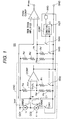
- FIG. 1 shows an embodiment of a soft-start circuit of a switching power source.
- the reference character OSC indicates a triangular wave generating circuit (the portion surrounded by a dot line), the reference character SS indicates a soft-start circuit, and the reference character PWMCOMP indicates a PWM comparator.
- the triangular wave generating circuit OSC comprises a series circuit composed of constant current sources CC1, CC2 and a switch SW1; a series circuit composed of a timing capacitor CT and resistors Ra, Rd, Rb; a series circuit composed of a resistor Rc and a switch SW2; and a comparator COMP.
- the soft-start circuit SS comprises a series circuit composed of resistors Ra', Rd', Rb'; a series circuit composed of a resistor Rc' and a switch SW3; a switch SW4; a counting circuit COUNT; and an AND circuit AND.
- One end of the resistor Rc' and one end of the switch SW4 are connected to a point of intersection of the resistors Rd' and Rb'.
- two output terminals of the counting circuit COUNT are individually connected to control input terminals of the switches SW3 and SW4, and one of the output terminals (connection of the control input to the switch SW3 side) of the counting circuit COUNT is connected to one of input terminals of the AND circuit AND, and further, an output terminal of the AND circuit AND is connected to the counting circuit COUNT.
- the other input terminal of the AND citcuit AND is connected to the comparator COMP of the triangular wave generating circuit OSC.
- circuit UVL is connected to an input terminal RST of the counting circuit COUNT.
- a first input terminal (+) is connected to an error amplifier EA (refer to FIG. 10 to be described later), and a second input terminal (+) is connected to the point of intersection of the resistors Rd' and Rb' of the soft-start circuit SS, as described above, and an input terminal (-) is connected to one end of the timing capacitor CT.
- an output voltage Vref of a reference voltage generating circuit VREF (refer to FIG. 10 to be described later) is supplied to one end of the resistor Ra of the triangular wave generating circuit OSC and one end of the resistor Ra' of the soft-start circuit SS.
- Operation of the triangular wave generating circuit is that a current value Io of a constant current source CC1 is always conducted to the timing capacitor CT.
- a terminal voltage VCT of the timing capacitor CT exceeds a threshold voltage VH of the comparator COMP
- the switch SW1 is turned on by an output of the comparator COMP and at the same time the switch SW2 is also turned on.
- the timing capacitor CT is started to discharge by a current value 4 ⁇ Io of a constant current source CC2, and the terminal voltage VCT of the timing capacitor CT gradually decreases.
- the two threshold voltages VH and VL of an upper and a lower limit values of voltage of the triangular wave can be calculated from the following equations, where values of the resistors Ra, Rd, Rb, Rc are expressed by Ra, Rd, Rb, Rc, and the output voltage of the reference voltage generating circuit VREF is expressed by Vref.
- VH Rd + Rb Ra + Rd + Rb •
- Vref HL ( Rd + Rb )/ / Rc Ra + ( Rd + Rb )/ / Rc • Vref
- the triangular wave having the oscillation frequency fOSC is generated in the triangular wave generating circuit, as described above, operation of the soft-start circuit SS using the triangular wave will be described below, referring to operating waveform of FIG. 2.
- the UVL circuit when the power is turned on and the input voltage VIN to the switching power source is low, the UVL circuit is initially operated to turn the PWM pulse off. When the UVL operation is released, the triangular wave generating circuit OSC starts to generate the triangular wave of FIG. 2 through the operation described above.
- the counting circuit COUNT of the soft-start circuit SS starts counting of the output pulses of the comparator COMP of the triangular wave generating circuit OSC. Then, since the counting time in the counting circuit COUNT is in a tsoft1 period of the soft-start time period, the input (reference) voltage Vx of the PWM comparator PWMCOMP becomes 0 (zero) because the switch SW4 is kept to be turned on during this period, as shown in FIG. 2.
- the period tsoft1 is the period that the output of the triangular wave of the triangular wave generating circuit OSC is determined, and also the period for preventing erroneous operation (a failure)of the main switch SW.
- the switch SW4 is turned off and the switch SW3 is turned on when the counting circuit COUNT progresses counting of the output pulses of the comparator COMP and the counting time enters into the tsoft2 period of the soft-start time period
- the reference voltage Vx of the PWM comparator PWMCOMP becomes a value VSF, as shown in FIG. 2.
- the PWM comparator PWMCOMP performs comparing operation between the triangular wave and the reference voltage Vx to generate and output PWM pulses having a narrow pulse width.
- the period tsoft2 is the period for preventing occurrence of overshoot at starting operation of the power source by narrowing the ON time period of the main SW. Further, when counting of the output pulses of the comparator COMP is progressed and the counting time exceeds the period tsoft1 + tsoft2 of the soft-start time period, the switches SW 4 and SW3 are turned off. Therefore, the AND circuit AND prohibits the pulses from inputting to the counting circuit COUNT, and the value of the reference voltage Vx is switched to a value VDB, as shown in FIG. 2, and thus the soft-start operation at starting the power source is completed and normal operation of the power source is started.
- the PWM comparator PWMCOMP generates PWM pulses by comparing the triangular wave of the triangular wave generating circuit OSC with an output of the error amplifier EA as the reference voltage.
- Vx VDB is for setting a dead band duty, that is, the PWM pulse width is restricted to exceed the limiting value.
- the relationship among VDB or VSF and the voltage setting resistance values is as follows.
- VDB Rb ' Ra '+ Rd '+ Rb ' • Vref
- VSF Rb / / Rc Ra '+ Rd '+( Rb' / / Rc ') • Vref
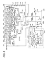
- FIG. 3 is a detailed circuit diagram showing the embodiment of a soft-start circuit of the switching power source of FIG. 1.
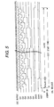
- the switches SW3, SW4 of the soft-start circuit SS are replaced with a single channel MOS, and the counting circuit COUNT and the AND circuit AND are constructed of a sequential circuit using flip-flops FF1 to FF9 for dividing the output pulse of the triangular wave generating circuit OSC; and a plurality of NAND circuit NA21 to NA34 for generating timings of the SW3, SW4, shown in FIG. 5; and a plurality of inverter circuits I12 to I44.
- an embodiment of a flip-flop used for the flip-flops FF1 to FF9 is as shown in FIG. 4.
- the same means as an upper-and-lower value setting part composed of a resistor network Ra to Rd and a switch SW2 of the triangular wave generating circuit OSC is used, and the same kinds and shapes of resistors as the resistors for setting the upper limit value VH and the lower limit value VL of the triangular wave of the triangular wave generating circuit OSC are used, and further the same reference voltage Vref is used. Therefore, the method of relatively setting voltages suitable for LSI can be formed because the set values of VSF, VDB as the Vx values can be highly accurately set between the voltages VH and VL, and accordingly the stable values of VSF and VDB can be obtained. Futher, since the soft-start time period can be obtained from the counting circuit using the output pulses of the triangular wave generating circuit OSC, no external capacitor is necessary, differently from the conventional soft-start circuit, and consequently the external parts can be eliminated.
- the Vx value is composed of the two values of VSF and VDB in the above-described embodiment, the Vx value may be switched in multi-steps, as shown in FIG. 6.
- FIG. 6 shows three-step switching, but the number of steps is not limited. Operation of FIG. 6 can be performed by connecting circuits equivalent to the series circuit composed of the resistor Rc' and the switch SW3 to the series circuit composed of the resistor Rc' and the switch SW3 in parallel, and changing the sequential circuit of the counting circuit COUNT of FIG. 3 so as to generates tsoft2, tsoft3, tsoft4 of the soft-start time period for controlling the plurality of switches (here, the structure of the sequential circuit for controlling the plurality of switches is not shown).
- Vx values of VSF, VSF2, VSF3 can be obtained by determining resistor values so as to satisfy Equation (4).
- the Vx value can be also increased stepwise by simulating the exponential function voltage using a CR circuit or the integration voltage using a capacitor in the conventional case of using the external capacitor.
- FIG. 12 As a method of multi-step switching, there is, for example, a construction of FIG. 12 in which the resistor Rc' is divided into a plurality of parts, and the divided resistors are connected in series, and a switch is individually arranged in both ends of each of all the divided resistors except one of the divided resistor. Operation of the circuit of FIG. 12 will be described below as a circuit performing the soft-start operation of FIG. 6.
- the multi-step switching can be performed through the method as described above.
- FIG. 7 is an example of a circuit structure capable of setting a four-system soft-start time period.
- a selector composed of flop-flops FF11 to FF14; inverters I15 to I54; AND circuits AN21 to AN28; and OR circuits OR21 to OR24 is arranged in the front stage of the counting circuit COUNT, and the soft-start time period is changed by determining based on 2-bit external set codes D0, D1 through a decoder DECOD and the selector whether or not the flip-flop signal is allowed to pass through the first stage, the second stage, ...
- setting of the soft-start time periods is not limited to this type of series.
- number of flip-flop stages is not limited to four stages.
- FIG. 8 In addition to the structure of FIG. 7 for changing the soft-start time periods to arbitrary time periods, another embodiment is shown in FIG. 8.
- a 95 % voltage of the reference voltage Vref of the reference voltage generating circuit VREF is compared with a one-half voltage of the DC converted output Vcc of the power source using a comparator COMF1, and the switch SW3 is turned on when the voltage Vcc exceeds a 95 % of the final value (the operating waveform is similar to that of FIG. 2).
- This method can automatically change the soft-start time period regardless of a load condition or values L, C of an output filter because the DC converted output Vcc of the power source is monitored.
- This part serves to determine only the time period tsoft2 in the FIG. 2, and accordingly the counting circuit is necessary in order to determine the time period tsoft1, as shown in FIG. 1.
- the logic of sequential circuit can be simplified because number of the flip-flop stages can be made 2 to 3 stages.
- FIG. 9 shows a further embodiment in which the part of the tsoft2 of FIG. 8 is divided into plural parts.
- the reference voltage Vref is divided using a plurality of resistors to form many divided voltages, and the many divided voltages are individually compared with a one-half voltage of the DC converted output Vcc of the power source using a plurality of comparators COMF1 to COMPn, and it is determined based on the comparing results which switch or switches among the switches SW1 to SWn (the switch side is not shown in the figure) are turned on through a decoder DECOD2.
- FIG. 10 is a functional block diagram of an embodiment of a switching power source to which the soft-start circuit in accordance with the present invention is applied.
- the switching power source of FIG. 10 comprises a main switch SW; a flywheel diode D; an over current sensor CS; an over current comparison voltage CLREF; an over current comparator CLCOMP; a driver circuit DRV; a NOR circuit NOR; a source grounding circuit composed of a constant current source CC and a single channel MOS M6; a PWM comparator PWMCOMP; a triangular wave generating circuit OSC; an error amplifier EA; a UVL (under voltage lock) circuit UVL; an over voltage detecting circuit OVP; a soft-start circuit SS having a DB (dead band) function in accordance with the present invention; an inner power source Vinner, a reference voltage generating circuit VREF; a resistor RT and a capacitor CT for setting an oscillation frequency of the triangular wave generating circuit OSC; dividing
- the terminals of the power source LSI are an input power supply terminal VIN; an output terminal VOUT; and a grounding terminal GRD.
- the external parts used are only an input capacitor Ci connected to the input power supply terminal VIN; and an inductor L and an output capacitor Co connected between the output terminal VOUT and the grounding terminal GRD. Therefore, it is possible to form an LSI without any external adjusting parts necessary for the control circuit of the power source.
- the soft-start circuit in accordance with the present invention can be applied to a switching power source of a synchronous rectification type.
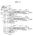
- FIG. 11 shows an embodiment in which the power source described above is applied to a power source circuit of a transceiver of DeviceNet (DeviceNet: a registered trademark of ODVA (Open DeviceNet Vendor Association)).
- DeviceNet DeviceNet: a registered trademark of ODVA (Open DeviceNet Vendor Association)
- a plurality of nodes 1 to n are connected to a serial interface bus cable (shield wire is not shown in the figure) composed of a pair of power wires V+ and V- and a pair of signal wires CANH and CANL.
- Each of the nodes (description will be made only on NODE1) is composed of a transceiver TRNCV1; a node power source PS1; a microcomputer/ CAN controller MPU1; and a circuit APP1 specific to an application.
- the transceiver TRNCV1 communicates with the other transceivers through the pair of signal wires CANH, CANL which are terminated by two resistors RTEM1 and RTEM2. Electric power is supplied to the transceiver TRNCV1 from a network power source PSNW connected to the power wires V+, V- through a power source circuit PS1.
- a network power source PSNW connected to the power wires V+, V- through a power source circuit PS1.
- the power source circuits PS1 to PSn are started at a time.
- a load as heavy as more than 1.5 times of normal load may be put on the network power supply at starting operation of the power source. Therefore, it is necessary to use a power source having a large current capacity for the network power source PSNW.
- the node power source containing the soft-start circuit As that of the present embodiment, a power source having a small current capacity can be used for the network power source PSNW, and any external capacitor used in a conventional soft-start circuit is not necessary in order to perform soft starting. Therefore, number of the parts can be reduced, and accordingly the cost can be reduced. Furthermore, the transceiver and the node power source an be implemented on a single chip LSI.
- the present switching power source described above can be applied to a power source of the other field network transceiver such as CAN (controller area network) of a serial bus system capable of performing real time processing.
- CAN controller area network
- the soft-start circuit of the switching power source comprises the soft-start reference value setting part composed of the group of resistance networks and the group of switches using the same means as the upper-and-lower limit setting part composed of networks and switches for setting the upper and the lower limits of the amplitude of triangular wave of the triangular generating circuit, and by counting cycles of the triangular wave of the triangular wave generating circuit using the counting circuit at starting operation of the power source, the group of switches are sequentially switched to generate a comparing voltage, and as the result of comparison of the comparing voltage with the triangular wave, output can be generated so as to gradually increase the PWM pulse width from the minimum width. Therefore, the soft-start circuit having a simple circuit structure can be implemented in an LSI. Accordingly, since the external parts become unnecessary, number of the parts can be reduced, and the apparatus can be made small in size and low in cost.
- the plurality of comparators are used instead of the counting circuit, and the group of switches are switched in decreasing order of the outputs of the plurality of comparators each indicating the difference between the reference voltage and the DC converted output voltage of the power source.
- the PWM pulse width of the PWM comparator can be gradually increased from the minimum width. Therefore, the same effects as the effects in the above can be obtained. Furthermore, there is an effect in that it is unnecessary to change the soft-start time period depending on the load or the values of L and C of the filter.
- the soft-start circuit can be applied to not only the node power source for DeviceNet (R) transceiver, but also to the power source for the other field network transceiver such as CAN, SDS (smart distributed system) PROFIBUS and so on, and accordingly a wide application of the soft-start circuit can be expected.
- R DeviceNet
- SDS smart distributed system
- the power source LSI without external parts can be materialized, noise generated from the power source can be minimized by integrating, for example, the transceiver LSI and the power source LSI into a single chip.
- the LSI by applying the LSI to an apparatus or a system, the cost of the apparatus or the system can be reduced.
Landscapes
- Engineering & Computer Science (AREA)
- Power Engineering (AREA)
- Dc-Dc Converters (AREA)
Abstract
In a switching power source comprising a triangular
wave generating circuit and an error amplifier and a PWM
comparator, in normal time PWM pulses being obtained by
comparing an output amplitude of triangular wave of the
triangular wave generating circuit with an output voltage
of the error amplifier as a reference voltage using the PWM
comparator, the soft-start circuit of the switching power
source comprises a soft-start reference value setting part
composed of a group of resistance networks and a group of
switches using the same means as an upper-and-lower limit
setting part, composed of networks and switches, for
setting an upper and a lower limits of the amplitude of
triangular wave of the triangular generating circuit; and a
counting circuit for counting cycles of the triangular wave
of the triangular wave generating circuit to obtain a
plurality of arbitrary soft-start timings in order to
switch the group of switches.
Description
The present invention relates to a soft-start circuit
for a switching power source, and particularly to a soft-start
circuit suitable for being implemented in a power
source LSI chip.
The soft-start circuit for the switching power source
is a circuit for preventing occurrence of an overshoot (a
rush current flowing through a main SW) at starting the
switching power source by gradually opening a PWM pulse
width from a minimum pulse width to slowly increasing a DC
converted output of the power source. As known methods of
performing soft start, there are methods of performing soft
start using an exponential function voltage of a CR circuit
or using an integrated voltage of a capacitor are disclosed
in Japanese Patent Application Laid-Open No.8-317637,
Japanese Patent Application Laid-Open No.9-233806, USP-5675485;
and a method of generating a PWM signal using a
digital circuit structure according to an instruction of a
microcomputer is disclosed in Japanese Patent Application
Laid-Open No.9-74737; and a method of generating a ramp
voltage according to an instruction data of a microcomputer
through a D/A converter is disclosed in Japanese Patent
Application Laid-Open No.2-7115.
In order solve the above problem, in the first method,
an external CR circuit or a circuit composed of a constant
current source and an external capacitor is added to the
switching power source, and the soft-start time period is
determined by a time constant of the CR circuit or an
integrating time of the capacitor. There is a problem that
the capacitor can not be implemented in the power source
LSI because a large capacitor of several tens nF to several
µF is necessary to obtain the soft-start time period of
several ms to several tens ms.
On the other hand, since the second or the third
method uses a mainly digital circuit structure suitable for
LSI, the digital circuit can be implemented in the LSI.
However, because the digital circuit is large in circuit
scale and soft-started (or initialized) by microcomputer
control, it is necessary to start up a power source of the
microcomputer before starting the controlled circuit (the
power source circuit). Therefore, the second or the third
method has a problem in that the method does not fit to
general-purpose switching power sources which do not
require microcomputer control.
An object of the present invention is to materialize
a soft-start circuit of a switching power source, and
particularly to materialize a soft-start circuit without
using any external capacitor in order to eliminate external
parts. Another object of the present invention is to
materialize a power source IC small in scale of the soft-start
circuit and suitable for a general-purpose switching
power source which does not require microcomputer control.
A feature of a soft-start circuit of a switching
power source in accordance with the present invention is
that in the switching power source comprising a triangular
wave generating circuit and an error amplifier and a PWM
comparator, in normal time PWM pulses being obtained by
comparing an output amplitude of triangular wave of the
triangular wave generating circuit with an output voltage
of the error amplifier as a reference voltage using the PWM
comparator, the soft-start circuit of the switching power
source comprises a soft-start reference value setting part
composed of a group of resistance networks and a group of
switches using the same means as an upper-and-lower limit
setting part, composed of networks and switches, for
setting an upper and a lower limits of the amplitude of
triangular wave of the triangular generating circuit; and a
counting circuit for counting cycles of the triangular wave
of the triangular wave generating circuit to obtain a
plurality of arbitrary soft-start time periods in order to
switch the group of switches.
Another feature of a soft-start circuit of a
switching power source in accordance with the present
invention is constructed in such that a plurality of
comparators are used instead of the counting circuit, and
each of a plurality of reference voltages extracted from
arbitrary voltage dividing points of an output voltage of a
reference voltage generating circuit is individually added
to one input terminal of each of the plurality of
comparators, and a voltage corresponding to a DC converted
output of the power source is input to the other input
terminal of each of all the comparators.
In order to generate the plurality of reference
voltages in the soft-start reference value setting part at
starting the power source, cycles of the triangular wave of
the triangular wave generating circuit are counted using
the counting circuit, and the group of switches described
above are sequentially switched every time when the
calculated time reaches to each desired time. By doing so,
the width of PWM pulse of the PWM comparator can be
gradually increased, and therefore, the soft-start circuit
having a simple circuit structure can be implemented in an
LSI.
On the other hand, in the case where the plurality of
comparators are used instead of the counting circuit
described above, the group of switches described above are
sequentially switched in decreasing order of difference
between the reference voltage and the DC converted output
voltage of the power source in outputs of the plurality of
comparators. By doing so, the width of PWM pulse of the PWM
comparator described above is gradually increased from a
minimum width toward a wider width, and similarly, the
soft-start circuit having a simple circuit structure can be
implemented in an LSI.
The above-mentioned features and the other features
of the present invention will be described below.
FIG. 1 shows an embodiment of a soft-start circuit of
a switching power source. In FIG. 1, the reference
character OSC indicates a triangular wave generating
circuit (the portion surrounded by a dot line), the
reference character SS indicates a soft-start circuit, and
the reference character PWMCOMP indicates a PWM comparator.
The triangular wave generating circuit OSC comprises a
series circuit composed of constant current sources CC1,
CC2 and a switch SW1; a series circuit composed of a timing
capacitor CT and resistors Ra, Rd, Rb; a series circuit
composed of a resistor Rc and a switch SW2; and a
comparator COMP. A point of intersection of the constant
current sources CC1 and CC2 and one end of the timing
capacitor CT are connected to an input terminal (+) of the
comparator COMP, and a point of intersection of the
resistors Ra and Rd and one end of the resistor Rc are
connected to an input terminal (-) of the comparator COMP.
Further, the output terminal of the comparator COMP is
connected to input control terminals of the switches SW1
and SW2. The soft-start circuit SS comprises a series
circuit composed of resistors Ra', Rd', Rb'; a series
circuit composed of a resistor Rc' and a switch SW3; a
switch SW4; a counting circuit COUNT; and an AND circuit
AND. One end of the resistor Rc' and one end of the switch
SW4 are connected to a point of intersection of the
resistors Rd' and Rb'. As shown in the figure, two output
terminals of the counting circuit COUNT are individually
connected to control input terminals of the switches SW3
and SW4, and one of the output terminals (connection of the
control input to the switch SW3 side) of the counting
circuit COUNT is connected to one of input terminals of the
AND circuit AND, and further, an output terminal of the AND
circuit AND is connected to the counting circuit COUNT. The
other input terminal of the AND citcuit AND is connected to
the comparator COMP of the triangular wave generating
circuit OSC. An output of a UVL (under voltage lock, refer
to FIG. 10 to be described later) circuit UVL is connected
to an input terminal RST of the counting circuit COUNT.
Among three input terminals of the PWM comparator PWMCOMP,
a first input terminal (+) is connected to an error
amplifier EA (refer to FIG. 10 to be described later), and
a second input terminal (+) is connected to the point of
intersection of the resistors Rd' and Rb' of the soft-start
circuit SS, as described above, and an input terminal (-)
is connected to one end of the timing capacitor CT. Further,
an output voltage Vref of a reference voltage generating
circuit VREF (refer to FIG. 10 to be described later) is
supplied to one end of the resistor Ra of the triangular
wave generating circuit OSC and one end of the resistor Ra'
of the soft-start circuit SS.
Operation of the circuit of FIG. 1 constructed as
above will be described below.
Operation of the triangular wave generating circuit
is that a current value Io of a constant current source CC1
is always conducted to the timing capacitor CT. When a
terminal voltage VCT of the timing capacitor CT exceeds a
threshold voltage VH of the comparator COMP, the switch SW1
is turned on by an output of the comparator COMP and at the
same time the switch SW2 is also turned on. Then, the
timing capacitor CT is started to discharge by a current
value 4 · Io of a constant current source CC2, and the
terminal voltage VCT of the timing capacitor CT gradually
decreases. When the terminal voltage VCT becomes below the
threshold voltage VL of the comparator COMP, both of the
switches SW1 and SW2 are again switched off by the output
of the comparator COMP to stop the discharge of the current
value 4 · Io of a constant current source CC2. By repeating
the above, the oscillation operation of the triangular wave
is performed.
The two threshold voltages VH and VL of an upper and
a lower limit values of voltage of the triangular wave can
be calculated from the following equations, where values of
the resistors Ra, Rd, Rb, Rc are expressed by Ra, Rd, Rb,
Rc, and the output voltage of the reference voltage
generating circuit VREF is expressed by Vref.
VH = Rd + Rb Ra + Rd + Rb •Vref
HL = (Rd + Rb )/ /Rc Ra + (Rd + Rb )/ /Rc • Vref
An oscillation frequency fOSC of the triangular wavw
generating circuit OSC can be calculated from the
reciprocal of the sum of charging time period t1 and
discharging time period t2 of the timing capacitor CT, and
the t1 and t2 are expressed by t1 = CT (VH - VL)/Io and t2
= CT (VH - VL)/(3 · Io), respectively. Therefore, the
oscillation frequency fOSC becomes as follows.
fOSC = 1/(t1 + t2) = 0.75 · Io/{CT (VH - VL)}
Assuming that Io = 10 µA, CT = 50 pF and VH - VL = 0.6 V,
fOSC becomes 250 kHz. In a case of high speed operation,
the oscillation frequency generally becomes a value smaller
than the calculated value because the delay time of the
comparator COMP is added to the time period t1 + t2.
Since the triangular wave having the oscillation
frequency fOSC is generated in the triangular wave
generating circuit, as described above, operation of the
soft-start circuit SS using the triangular wave will be
described below, referring to operating waveform of FIG. 2.
Referring to FIG. 2, when the power is turned on and the
input voltage VIN to the switching power source is low, the
UVL circuit is initially operated to turn the PWM pulse off.
When the UVL operation is released, the triangular wave
generating circuit OSC starts to generate the triangular
wave of FIG. 2 through the operation described above. On
the other hand, since the UVL operation of the reset input
RST of the counting circuit COUNT of the soft-start circuit
SS is also released, the counting circuit COUNT of the
soft-start circuit SS starts counting of the output pulses
of the comparator COMP of the triangular wave generating
circuit OSC. Then, since the counting time in the counting
circuit COUNT is in a tsoft1 period of the soft-start time
period, the input (reference) voltage Vx of the PWM
comparator PWMCOMP becomes 0 (zero) because the switch SW4
is kept to be turned on during this period, as shown in FIG.
2. That is, the period tsoft1 is the period that the output
of the triangular wave of the triangular wave generating
circuit OSC is determined, and also the period for
preventing erroneous operation (a failure)of the main
switch SW. Next, because the switch SW4 is turned off and
the switch SW3 is turned on when the counting circuit COUNT
progresses counting of the output pulses of the comparator
COMP and the counting time enters into the tsoft2 period of
the soft-start time period, the reference voltage Vx of the
PWM comparator PWMCOMP becomes a value VSF, as shown in FIG.
2. During this period, the PWM comparator PWMCOMP performs
comparing operation between the triangular wave and the
reference voltage Vx to generate and output PWM pulses
having a narrow pulse width. That is, the period tsoft2 is
the period for preventing occurrence of overshoot at
starting operation of the power source by narrowing the ON
time period of the main SW. Further, when counting of the
output pulses of the comparator COMP is progressed and the
counting time exceeds the period tsoft1 + tsoft2 of the
soft-start time period, the switches SW 4 and SW3 are
turned off. Therefore, the AND circuit AND prohibits the
pulses from inputting to the counting circuit COUNT, and
the value of the reference voltage Vx is switched to a
value VDB, as shown in FIG. 2, and thus the soft-start
operation at starting the power source is completed and
normal operation of the power source is started. The PWM
comparator PWMCOMP generates PWM pulses by comparing the
triangular wave of the triangular wave generating circuit
OSC with an output of the error amplifier EA as the
reference voltage. Therein, Vx = VDB is for setting a dead
band duty, that is, the PWM pulse width is restricted to
exceed the limiting value. The relationship among VDB or
VSF and the voltage setting resistance values is as follows.
Letting the resistance values of the resistors Ra', Rd',
Rb', Rc' be Ra', Rd', Rb', Rc', respectively,
VDB = Rb ' Ra '+Rd '+Rb ' • Vref
VSF = Rb / /Rc Ra '+Rd '+(Rb' / /Rc ') • Vref
FIG. 3 is a detailed circuit diagram showing the
embodiment of a soft-start circuit of the switching power
source of FIG. 1. In FIG. 3, the switches SW3, SW4 of the
soft-start circuit SS are replaced with a single channel
MOS, and the counting circuit COUNT and the AND circuit AND
are constructed of a sequential circuit using flip-flops
FF1 to FF9 for dividing the output pulse of the triangular
wave generating circuit OSC; and a plurality of NAND
circuit NA21 to NA34 for generating timings of the SW3, SW4,
shown in FIG. 5; and a plurality of inverter circuits I12
to I44. Therein, an embodiment of a flip-flop used for the
flip-flops FF1 to FF9 is as shown in FIG. 4.
In the construction and the operation described above,
in the soft-start reference value setting part, the same
means as an upper-and-lower value setting part composed of
a resistor network Ra to Rd and a switch SW2 of the
triangular wave generating circuit OSC is used, and the
same kinds and shapes of resistors as the resistors for
setting the upper limit value VH and the lower limit value
VL of the triangular wave of the triangular wave generating
circuit OSC are used, and further the same reference
voltage Vref is used. Therefore, the method of relatively
setting voltages suitable for LSI can be formed because the
set values of VSF, VDB as the Vx values can be highly
accurately set between the voltages VH and VL, and
accordingly the stable values of VSF and VDB can be
obtained. Futher, since the soft-start time period can be
obtained from the counting circuit using the output pulses
of the triangular wave generating circuit OSC, no external
capacitor is necessary, differently from the conventional
soft-start circuit, and consequently the external parts can
be eliminated.
Although the Vx value is composed of the two values
of VSF and VDB in the above-described embodiment, the Vx
value may be switched in multi-steps, as shown in FIG. 6.
FIG. 6 shows three-step switching, but the number of steps
is not limited. Operation of FIG. 6 can be performed by
connecting circuits equivalent to the series circuit
composed of the resistor Rc' and the switch SW3 to the
series circuit composed of the resistor Rc' and the switch
SW3 in parallel, and changing the sequential circuit of the
counting circuit COUNT of FIG. 3 so as to generates tsoft2,
tsoft3, tsoft4 of the soft-start time period for
controlling the plurality of switches (here, the structure
of the sequential circuit for controlling the plurality of
switches is not shown). In that case, the necessary Vx
values of VSF, VSF2, VSF3 can be obtained by determining
resistor values so as to satisfy Equation (4). By doing as
described above, the Vx value can be also increased
stepwise by simulating the exponential function voltage
using a CR circuit or the integration voltage using a
capacitor in the conventional case of using the external
capacitor.
Further, as a method of multi-step switching, there
is, for example, a construction of FIG. 12 in which the
resistor Rc' is divided into a plurality of parts, and the
divided resistors are connected in series, and a switch is
individually arranged in both ends of each of all the
divided resistors except one of the divided resistor.
Operation of the circuit of FIG. 12 will be described below
as a circuit performing the soft-start operation of FIG. 6.
In the soft-start time period tsoft2, all of the newly
added switches and the switch SW3 are turned on, and during
the soft-start time periods tsoft3 and tsoft4 for
controlling the switches, the newly added switches are
turned off so that the reference voltage Vx may be
gradually increased, and then the switch SW3 is turned off
at the time when the total soft-start operation is
completed. Thus, the multi-step switching can be performed
through the method as described above.
Next, another embodiment for changing the soft-start
time period to an arbitrary time period is shown in FIG. 7.
The embodiment of FIG. 7 is an example of a circuit
structure capable of setting a four-system soft-start time
period. In the embodiment of FIG. 7, a selector composed of
flop-flops FF11 to FF14; inverters I15 to I54; AND circuits
AN21 to AN28; and OR circuits OR21 to OR24 is arranged in
the front stage of the counting circuit COUNT, and the
soft-start time period is changed by determining based on
2-bit external set codes D0, D1 through a decoder DECOD and
the selector whether or not the flip-flop signal is allowed
to pass through the first stage, the second stage, ...
Although the description hear has been made on the example
in which the soft-start time periods are set by the nth
power of 2, setting of the soft-start time periods is not
limited to this type of series. Further, number of flip-flop
stages is not limited to four stages.
In addition to the structure of FIG. 7 for changing
the soft-start time periods to arbitrary time periods,
another embodiment is shown in FIG. 8. In FIG. 8, as an
example, a 95 % voltage of the reference voltage Vref of
the reference voltage generating circuit VREF is compared
with a one-half voltage of the DC converted output Vcc of
the power source using a comparator COMF1, and the switch
SW3 is turned on when the voltage Vcc exceeds a 95 % of the
final value (the operating waveform is similar to that of
FIG. 2). This method can automatically change the soft-start
time period regardless of a load condition or values
L, C of an output filter because the DC converted output
Vcc of the power source is monitored. This part serves to
determine only the time period tsoft2 in the FIG. 2, and
accordingly the counting circuit is necessary in order to
determine the time period tsoft1, as shown in FIG. 1.
However, the logic of sequential circuit can be simplified
because number of the flip-flop stages can be made 2 to 3
stages.
FIG. 9 shows a further embodiment in which the part
of the tsoft2 of FIG. 8 is divided into plural parts. The
reference voltage Vref is divided using a plurality of
resistors to form many divided voltages, and the many
divided voltages are individually compared with a one-half
voltage of the DC converted output Vcc of the power source
using a plurality of comparators COMF1 to COMPn, and it is
determined based on the comparing results which switch or
switches among the switches SW1 to SWn (the switch side is
not shown in the figure) are turned on through a decoder
DECOD2.
FIG. 10 is a functional block diagram of an
embodiment of a switching power source to which the soft-start
circuit in accordance with the present invention is
applied. The switching power source of FIG. 10 comprises a
main switch SW; a flywheel diode D; an over current sensor
CS; an over current comparison voltage CLREF; an over
current comparator CLCOMP; a driver circuit DRV; a NOR
circuit NOR; a source grounding circuit composed of a
constant current source CC and a single channel MOS M6; a
PWM comparator PWMCOMP; a triangular wave generating
circuit OSC; an error amplifier EA; a UVL (under voltage
lock) circuit UVL; an over voltage detecting circuit OVP; a
soft-start circuit SS having a DB (dead band) function in
accordance with the present invention; an inner power
source Vinner, a reference voltage generating circuit VREF;
a resistor RT and a capacitor CT for setting an oscillation
frequency of the triangular wave generating circuit OSC;
dividing voltage input resistors R1 and R2 for performing
negative feedback a DC converted output Vcc of the power
source to the error amplifier EA; a feedback circuit
composed of a resistor RF and a capacitor CF; and single
channel MOS's M1 to M5. These blocks are connected as shown
in FIG. 10. The terminals of the power source LSI are an
input power supply terminal VIN; an output terminal VOUT;
and a grounding terminal GRD. The external parts used are
only an input capacitor Ci connected to the input power
supply terminal VIN; and an inductor L and an output
capacitor Co connected between the output terminal VOUT and
the grounding terminal GRD. Therefore, it is possible to
form an LSI without any external adjusting parts necessary
for the control circuit of the power source.
Further, the soft-start circuit in accordance with
the present invention can be applied to a switching power
source of a synchronous rectification type.
FIG. 11 shows an embodiment in which the power source
described above is applied to a power source circuit of a
transceiver of DeviceNet (DeviceNet: a registered trademark
of ODVA (Open DeviceNet Vendor Association)). Referring to
FIG. 11, a plurality of nodes 1 to n are connected to a
serial interface bus cable (shield wire is not shown in the
figure) composed of a pair of power wires V+ and V- and a
pair of signal wires CANH and CANL. Each of the nodes
(description will be made only on NODE1) is composed of a
transceiver TRNCV1; a node power source PS1; a
microcomputer/ CAN controller MPU1; and a circuit APP1
specific to an application. The transceiver TRNCV1
communicates with the other transceivers through the pair
of signal wires CANH, CANL which are terminated by two
resistors RTEM1 and RTEM2. Electric power is supplied to
the transceiver TRNCV1 from a network power source PSNW
connected to the power wires V+, V- through a power source
circuit PS1. In such a construction, when the network power
source PSNW is turned on, the power source circuits PS1 to
PSn are started at a time. In general, a load as heavy as
more than 1.5 times of normal load may be put on the
network power supply at starting operation of the power
source. Therefore, it is necessary to use a power source
having a large current capacity for the network power
source PSNW. By using the node power source containing the
soft-start circuit as that of the present embodiment, a
power source having a small current capacity can be used
for the network power source PSNW, and any external
capacitor used in a conventional soft-start circuit is not
necessary in order to perform soft starting. Therefore,
number of the parts can be reduced, and accordingly the
cost can be reduced. Furthermore, the transceiver and the
node power source an be implemented on a single chip LSI.
The present switching power source described above
can be applied to a power source of the other field network
transceiver such as CAN (controller area network) of a
serial bus system capable of performing real time
processing.
According to the above, the soft-start circuit of the
switching power source comprises the soft-start reference
value setting part composed of the group of resistance
networks and the group of switches using the same means as
the upper-and-lower limit setting part composed of networks
and switches for setting the upper and the lower limits of
the amplitude of triangular wave of the triangular
generating circuit, and by counting cycles of the
triangular wave of the triangular wave generating circuit
using the counting circuit at starting operation of the
power source, the group of switches are sequentially
switched to generate a comparing voltage, and as the result
of comparison of the comparing voltage with the triangular
wave, output can be generated so as to gradually increase
the PWM pulse width from the minimum width. Therefore, the
soft-start circuit having a simple circuit structure can be
implemented in an LSI. Accordingly, since the external
parts become unnecessary, number of the parts can be
reduced, and the apparatus can be made small in size and
low in cost.
Further, the plurality of comparators are used
instead of the counting circuit, and the group of switches
are switched in decreasing order of the outputs of the
plurality of comparators each indicating the difference
between the reference voltage and the DC converted output
voltage of the power source. By doing so, the PWM pulse
width of the PWM comparator can be gradually increased from
the minimum width. Therefore, the same effects as the
effects in the above can be obtained. Furthermore, there is
an effect in that it is unnecessary to change the soft-start
time period depending on the load or the values of L
and C of the filter.
Further, the soft-start circuit can be applied to not
only the node power source for DeviceNet (R) transceiver,
but also to the power source for the other field network
transceiver such as CAN, SDS (smart distributed system)
PROFIBUS and so on, and accordingly a wide application of
the soft-start circuit can be expected.
Further, since the power source LSI without external
parts can be materialized, noise generated from the power
source can be minimized by integrating, for example, the
transceiver LSI and the power source LSI into a single chip.
In addition, by applying the LSI to an apparatus or a
system, the cost of the apparatus or the system can be
reduced.
According to the present invention, it is possible to
materialize a soft-start circuit which does not use any
external capacitor.
Claims (8)
- A soft-start circuit of a switching power source, said switching power source comprising a triangular wave generating circuit and an error amplifier and a PWM comparator, in normal time PWM pulses being obtained by comparing an output amplitude of triangular wave of said triangular wave generating circuit with an output voltage of said error amplifier as a reference (comparing) voltage using said PWM comparator, wherein
the same means as an upper-and-lower limit setting part for setting an upper and a lower limits of the amplitude of triangular wave of said triangular generating circuit is provided, said same means as an upper-and-lower limit setting part being composed of networks and switches, and in said same means as an upper-and-lower limit setting part cycles of the triangular wave of said triangular wave generating circuit are counted using a counting circuit at starting the power source in order to generate a plurality of reference voltages, and when said counting time reaches a desired time, said reference voltage is sequentially switched to generate PWM pulses so that a PWM pulse width of said PWM comparator may be gradually increased from a minimum width toward a wider width. - A soft-start circuit of a switching power source according to claim 1, wherein relationship between the counting time and a generating time is set so as to become an exponential function voltage using a CR circuit or an integration voltage using a capacitor.
- A soft-start circuit of a switching power source according to any one of claim 1 and claim 2, wherein arbitrary time periods can be obtained by set codes in order to obtain desired start timings.
- A soft-start circuit of a switching power source according to claim 1, wherein a soft-start time period is determined by a voltage level before an output voltage of the switching power source reaches a final value, not determined by the counting circuit.
- A soft-start circuit of a switching power source, which has the both configurations according to claim 1 and claim 4.
- A soft-start circuit of a switching power source according to any one of claim 1 to claim 5, wherein a filter circuit is placed after said same means as the upper-and-lower limit setting part for setting an upper and a lower limits of the amplitude of triangular wave of said triangular generating circuit, said same means as the upper-and-lower limit setting part being composed of networks and switches.
- A network transceiver to which electric power is supplied from a switching power source having the soft-start circuit according to any one of claim 1 to claim 6.
- A switching power source having the soft-start circuit according to any one of claim 1 to claim 6.
Applications Claiming Priority (2)
| Application Number | Priority Date | Filing Date | Title |
|---|---|---|---|
| JP2001009659A JP3675339B2 (en) | 2001-01-18 | 2001-01-18 | Switching power supply |
| JP2001009659 | 2001-01-18 |
Publications (1)
| Publication Number | Publication Date |
|---|---|
| EP1235333A2 true EP1235333A2 (en) | 2002-08-28 |
Family
ID=18877101
Family Applications (1)
| Application Number | Title | Priority Date | Filing Date |
|---|---|---|---|
| EP01119453A Withdrawn EP1235333A2 (en) | 2001-01-18 | 2001-08-13 | Soft start circuit for switching power supply |
Country Status (4)
| Country | Link |
|---|---|
| US (1) | US6377480B1 (en) |
| EP (1) | EP1235333A2 (en) |
| JP (1) | JP3675339B2 (en) |
| KR (1) | KR20020061475A (en) |
Cited By (1)
| Publication number | Priority date | Publication date | Assignee | Title |
|---|---|---|---|---|
| US7638995B2 (en) | 2005-01-18 | 2009-12-29 | Freescale Semiconductor, Inc. | Clocked ramp apparatus for voltage regulator softstart and method for softstarting voltage regulators |
Families Citing this family (34)
| Publication number | Priority date | Publication date | Assignee | Title |
|---|---|---|---|---|
| US6813170B2 (en) | 2002-08-19 | 2004-11-02 | Semtech Corporation | Multiple output power supply having soft start protection for load over-current or short circuit conditions |
| JP2004166445A (en) * | 2002-11-15 | 2004-06-10 | Rohm Co Ltd | Dc-ac converter and its controller ic |
| BR0300173A (en) * | 2003-01-31 | 2004-10-26 | Engetron Engenharia Eletronica | Single-phase or multi-phase inverter power supply system |
| JP2005176476A (en) * | 2003-12-10 | 2005-06-30 | Seiko Instruments Inc | Switching regulator |
| US7250744B2 (en) * | 2004-04-26 | 2007-07-31 | Da Feng Weng | Quasi average current mode control scheme for switching power converter |
| US7095215B2 (en) * | 2004-06-04 | 2006-08-22 | Astec International Limited | Real-time voltage detection and protection circuit for PFC boost converters |
| US7088078B2 (en) * | 2004-06-04 | 2006-08-08 | Astec International Limited | Soft-start circuit for power converters |
| US6965223B1 (en) * | 2004-07-06 | 2005-11-15 | National Semiconductor Corporation | Method and apparatus to allow rapid adjustment of the reference voltage in a switching regulator |
| JP4359843B2 (en) * | 2004-10-14 | 2009-11-11 | 横河電機株式会社 | Output circuit |
| US7719249B2 (en) * | 2005-01-28 | 2010-05-18 | Semiconductor Components Industries, Llc | Soft-start circuit and method therefor |
| JP4764978B2 (en) * | 2005-02-03 | 2011-09-07 | 富士電機株式会社 | Switching power supply |
| JP2006333589A (en) * | 2005-05-25 | 2006-12-07 | Mitsumi Electric Co Ltd | Switching power supply device and control method thereof |
| CN101167236B (en) * | 2005-07-15 | 2010-08-25 | 半导体元件工业有限责任公司 | Power supply controller and method thereof |
| JP4862500B2 (en) * | 2006-06-05 | 2012-01-25 | 富士電機株式会社 | Soft start circuit and semiconductor device |
| JP5211523B2 (en) * | 2007-03-27 | 2013-06-12 | 富士通セミコンダクター株式会社 | DC-DC converter, power supply method and power supply system |
| US8026707B2 (en) * | 2007-08-29 | 2011-09-27 | Monolithic Power Systems, Inc. | Circuit system and method for reducing an in-rush current |
| JP2009033090A (en) * | 2007-12-27 | 2009-02-12 | Rohm Co Ltd | Drive device |
| TWI354875B (en) * | 2008-02-19 | 2011-12-21 | Realtek Semiconductor Corp | Soft start apparatus |
| US7808277B2 (en) * | 2008-09-18 | 2010-10-05 | Hewlett-Packard Development Company, L.P. | Bidirectional signal separation module for a bus converter |
| WO2010134516A1 (en) * | 2009-05-19 | 2010-11-25 | ローム株式会社 | Power supply device and electronic device provided with same |
| JP5398422B2 (en) * | 2009-08-24 | 2014-01-29 | 新日本無線株式会社 | Switching power supply |
| JP5398458B2 (en) * | 2009-10-07 | 2014-01-29 | 新電元工業株式会社 | Switching power supply |
| US8327165B2 (en) * | 2010-01-21 | 2012-12-04 | Dell Products L.P. | Soft start with active reset |
| JP2011151325A (en) * | 2010-01-25 | 2011-08-04 | Kyosan Electric Mfg Co Ltd | Led driving circuit, lamplight device, and signal lamplight device |
| US8456868B2 (en) * | 2010-04-30 | 2013-06-04 | Infineon Technologies Ag | Controller for a resonant switched-mode power converter |
| US8665611B2 (en) | 2010-04-30 | 2014-03-04 | Infineon Technologies Ag | Controller for a resonant switched-mode power converter |
| WO2012132221A1 (en) | 2011-03-28 | 2012-10-04 | ルネサスエレクトロニクス株式会社 | Pwm signal generating circuit and processor system |
| WO2012148977A1 (en) * | 2011-04-25 | 2012-11-01 | Fairchild Semiconductor Corporation | Soft-start control techniques for a switched-mode power supply |
| US9285812B2 (en) | 2013-02-01 | 2016-03-15 | Allegro Microsystems, Llc | Soft start circuits and techniques |
| US10003252B2 (en) | 2015-05-08 | 2018-06-19 | Analog Devices, Inc. | Over-current recovery including overshoot suppression |
| US9641073B2 (en) | 2015-09-04 | 2017-05-02 | Qualcomm Incorporated | Start up method for switching converters using the same reference voltage in the error amplifier and PWM comparator |
| US10826397B2 (en) * | 2018-09-03 | 2020-11-03 | Rohm Co., Ltd. | Switching power supply operable in an intermittent driving mode |
| CN113162386B (en) * | 2021-03-05 | 2023-09-26 | 广州大学 | A reference voltage soft-start circuit suitable for boost conversion circuits |
| CN114337266B (en) * | 2021-12-17 | 2023-12-26 | 上海晶丰明源半导体股份有限公司 | Switching power supply and control circuit for switching power supply |
Family Cites Families (17)
| Publication number | Priority date | Publication date | Assignee | Title |
|---|---|---|---|---|
| JPS6028036B2 (en) * | 1981-12-16 | 1985-07-02 | 横河電機株式会社 | integral circuit |
| IT1221246B (en) * | 1988-02-04 | 1990-06-27 | Sgs Thomson Microelectronics | POWER SUPPLY WITH OUTPUT VOLTAGE DEVELOPED GRADUALLY AT IGNITION |
| JP3251770B2 (en) * | 1994-06-02 | 2002-01-28 | ローム株式会社 | Power supply circuit for semiconductor integrated circuit |
| KR0119883B1 (en) | 1994-12-22 | 1997-10-30 | 김광호 | Controller for switching power supply and switching power supply using same |
| JPH08317637A (en) * | 1995-05-22 | 1996-11-29 | Nemic Lambda Kk | Soft start circuit for switching power-supply device |
| JPH0974737A (en) * | 1995-09-01 | 1997-03-18 | Canon Inc | PWM signal generator |
| KR0167900B1 (en) * | 1995-12-28 | 1999-03-20 | 김광호 | Soft-Start Pulse Width Modulation Integrated Circuits |
| US5698973A (en) * | 1996-07-31 | 1997-12-16 | Data General Corporation | Soft-start switch with voltage regulation and current limiting |
| GB9620890D0 (en) * | 1996-10-07 | 1996-11-27 | Thomson Multimedia Sa | Switch mode power supply |
| JP3798527B2 (en) * | 1997-08-29 | 2006-07-19 | 富士通株式会社 | DC-DC converter drive circuit control method, DC-DC converter control circuit, DC-DC converter |
| JPH10333626A (en) * | 1997-05-27 | 1998-12-18 | Fujitsu Ltd | Power supply modulation circuit |
| US5917313A (en) * | 1997-12-19 | 1999-06-29 | Stmicroelectronics, Inc. | DC-to-DC converter with soft-start error amplifier and associated method |
| JP4158285B2 (en) * | 1998-08-28 | 2008-10-01 | 株式会社デンソー | Electric load drive |
| US6118263A (en) * | 1999-01-27 | 2000-09-12 | Linear Technology Corporation | Current generator circuitry with zero-current shutdown state |
| JP2001008462A (en) * | 1999-06-16 | 2001-01-12 | Japan Storage Battery Co Ltd | Uninterruptible power system |
| US6188210B1 (en) * | 2000-01-13 | 2001-02-13 | Ophir Rf, Inc. | Methods and apparatus for soft start and soft turnoff of linear voltage regulators |
| US6316926B1 (en) * | 2000-05-19 | 2001-11-13 | Stmicroelectronics S.R.L. | Switching control circuit |
-
2001
- 2001-01-18 JP JP2001009659A patent/JP3675339B2/en not_active Expired - Fee Related
- 2001-08-13 EP EP01119453A patent/EP1235333A2/en not_active Withdrawn
- 2001-08-14 US US09/928,442 patent/US6377480B1/en not_active Expired - Fee Related
- 2001-08-31 KR KR1020010053158A patent/KR20020061475A/en not_active Ceased
Cited By (1)
| Publication number | Priority date | Publication date | Assignee | Title |
|---|---|---|---|---|
| US7638995B2 (en) | 2005-01-18 | 2009-12-29 | Freescale Semiconductor, Inc. | Clocked ramp apparatus for voltage regulator softstart and method for softstarting voltage regulators |
Also Published As
| Publication number | Publication date |
|---|---|
| JP3675339B2 (en) | 2005-07-27 |
| KR20020061475A (en) | 2002-07-24 |
| JP2002218737A (en) | 2002-08-02 |
| US6377480B1 (en) | 2002-04-23 |
Similar Documents
| Publication | Publication Date | Title |
|---|---|---|
| EP1235333A2 (en) | Soft start circuit for switching power supply | |
| US11081954B2 (en) | Phase shedding control method used in multiphase switching converters with daisy chain configuration | |
| EP0581016B1 (en) | Apparatus and method for forced sharing of switching losses of parallel connected transistors | |
| US20020130705A1 (en) | Charge pump mode transition control | |
| US9716436B2 (en) | Soft start controller of a converter | |
| JP2006509485A (en) | Multi-output DC-DC converter | |
| KR20080098396A (en) | LED driver circuit | |
| US6130528A (en) | Switching regulator controlling system having a light load mode of operation based on a voltage feedback signal | |
| US20220271668A1 (en) | Scalable multi-phase switching converter and converter module and control method thereof | |
| JP4026422B2 (en) | Power supply control circuit, multi-channel power supply circuit device, and soft start circuit | |
| CN113841326A (en) | Switching Converters with Multiple Driver Stages and Associated Modes | |
| CN116880668A (en) | Server | |
| JP2006197595A (en) | Method and circuit for galvanically isolated transmission of signal | |
| CN100435460C (en) | mode conversion control circuit and method for charge pump | |
| US20250079984A1 (en) | Conversion control circuit and method for use in stackable multiphase power converter | |
| JPH07129289A (en) | Device for recognizing bus line length | |
| JP7239756B1 (en) | DC-DC converter | |
| US12483140B2 (en) | Switching regulator and control circuit thereof and quick response method | |
| EP4637013A1 (en) | Control circuit, power conversion device, control method, and program | |
| CN112737321B (en) | Power conversion circuit with multi-function pin and multi-function setting method thereof | |
| JP3081387B2 (en) | Successive approximation type AD converter | |
| US6052075A (en) | Data processing device having a D/A function | |
| CN118944389A (en) | Switching power supply and its control circuit and fast response method | |
| CN120834729A (en) | Low inrush current power converter circuit | |
| WO2024104597A1 (en) | Method of operating a flying capacitor converter |
Legal Events
| Date | Code | Title | Description |
|---|---|---|---|
| PUAI | Public reference made under article 153(3) epc to a published international application that has entered the european phase |
Free format text: ORIGINAL CODE: 0009012 |
|
| AK | Designated contracting states |
Kind code of ref document: A2 Designated state(s): AT BE CH CY DE DK ES FI FR GB GR IE IT LI LU MC NL PT SE TR |
|
| AX | Request for extension of the european patent |
Free format text: AL;LT;LV;MK;RO;SI |
|
| STAA | Information on the status of an ep patent application or granted ep patent |
Free format text: STATUS: THE APPLICATION HAS BEEN WITHDRAWN |
|
| 18W | Application withdrawn |
Effective date: 20040210 |