EP1235053A2 - Apparatus and method for collecting and processing data from a plurality of sensors - Google Patents
Apparatus and method for collecting and processing data from a plurality of sensors Download PDFInfo
- Publication number
- EP1235053A2 EP1235053A2 EP02250475A EP02250475A EP1235053A2 EP 1235053 A2 EP1235053 A2 EP 1235053A2 EP 02250475 A EP02250475 A EP 02250475A EP 02250475 A EP02250475 A EP 02250475A EP 1235053 A2 EP1235053 A2 EP 1235053A2
- Authority
- EP
- European Patent Office
- Prior art keywords
- sense element
- bridge
- node
- signal
- condition responsive
- Prior art date
- Legal status (The legal status is an assumption and is not a legal conclusion. Google has not performed a legal analysis and makes no representation as to the accuracy of the status listed.)
- Granted
Links
Images



Classifications
-
- G—PHYSICS
- G01—MEASURING; TESTING
- G01D—MEASURING NOT SPECIALLY ADAPTED FOR A SPECIFIC VARIABLE; ARRANGEMENTS FOR MEASURING TWO OR MORE VARIABLES NOT COVERED IN A SINGLE OTHER SUBCLASS; TARIFF METERING APPARATUS; MEASURING OR TESTING NOT OTHERWISE PROVIDED FOR
- G01D3/00—Indicating or recording apparatus with provision for the special purposes referred to in the subgroups
- G01D3/028—Indicating or recording apparatus with provision for the special purposes referred to in the subgroups mitigating undesired influences, e.g. temperature, pressure
- G01D3/036—Indicating or recording apparatus with provision for the special purposes referred to in the subgroups mitigating undesired influences, e.g. temperature, pressure on measuring arrangements themselves
- G01D3/0365—Indicating or recording apparatus with provision for the special purposes referred to in the subgroups mitigating undesired influences, e.g. temperature, pressure on measuring arrangements themselves the undesired influence being measured using a separate sensor, which produces an influence related signal
Definitions
- This invention relates generally to systems for sensing a condition at a plurality of locations and more particularly to systems for conditioning multiple sense elements with a common electronic circuit.
- electro-hydraulic brake or EHB systems generally have six locations that require sensing of the fluid pressure.
- Pressure sensing is required at each wheel for closed loop brake force control, at a location to sense driver input and at the pressure accumulator to sense system reserve pressure.
- Hydraulic sensing points are all routed through the hydraulic control unit or HCU having a system controller, i.e., microprocessor, so that there exists one member at which all different hydraulic circuit pressures are sensed.
- the provision of six discrete pressure sensors with full conditioning electronics results in suitable operation; however, it also results in a total pressure sensor cost which is higher than desirable compared to the remaining system component costs.
- an object of the present invention to provide a reliable yet lower cost condition responsive sense system than the prior art system referenced above.
- Yet another object is the provision of a relatively low cost, accurate and reliable sense system responsive to pressure, acceleration, torque, force and the like and to an improved low cost method for conditioning condition responsive sense elements.
- a plurality of sense elements are connected to an ASIC with the output of any selected sense element being connected to a common signal conditioning circuit path by analog multiplexing.
- the sense element signal is conditioned by the signal conditioning circuit of the ASIC to provide partial conditioning comprising basic calibration data.
- Complete characterization data for all the sense elements is stored in non-volatile memory of the ASIC and is transferred to a host controller, e.g., microprocessor, upon command to enable the host controller to perform appropriate mathematical operations to provide the additional amount of compensation required to complete the signal conditioning.
- a diagnostic circuit path is included in the ASIC for diagnosing sense element and sense element connection faults.
- first and second fixed test sense elements are formed in the ASIC for diagnosing ASIC faults.
- the sense elements may be formed of individual strain bridges known in the art, such as silicon resistor bridges bonded to a diaphragm through glass material fired at high temperatures and adapted for placement in a fluid pressure port.
- the resistors in the bridge are made of silicon, they exhibit a piezoresistive effect exhibiting a change in resistance when subjected to strain.
- a voltage to the bridge By applying a voltage to the bridge, a small voltage change results at the output of the bridges.
- a circuit for six sense elements is shown; however, it will be realized that the circuit can be modified to accommodate more or fewer sense elements as desired.
- a bridge bias is provided through an electronically programmable resistor in series with the strain bridge.
- the resistor can be set either to a specific value in order to derive a temperature signal from the bridge or it can be set at zero to bias the bridge with the full supply voltage. Selection of the bias resistor value is accomplished via selection of a register value.
- Generation of the temperature signal utilizes the bridge temperature coefficient of resistance (TCR) to form a voltage divider with the low/zero TRC programmable resistor. Derivation of the temperature signal by this means is conventional.
- the bridge conditioning circuit functions with one bridge at a time, therefore, a means of switching bridge bias and each bridge output to the conditioning circuit input is provided. This is accomplished via analog multiplexers.
- the input to the conditioning circuit is controlled by three register values. All bridges are connected to a terminal of the ASIC at all times.
- two reference bridges are also included in the circuit and are selected via the analog multiplexer registers for the purpose of circuit diagnostic testing. The function of the reference bridges will be explained more below.
- Electronically programmable Offset and Gain correction of the signal proportional to pressure is provided through control of respective registers. This minimal amount of calibration is required to maximize the output range of the pressure signal in order to use the largest possible input range of the Analog to Digital Converter (ADC). By using this approach, the bit resolution of the ADC block can be reduced to the minimum acceptable level thereby reducing the size and cost of this circuit element.
- Optional input Low Pass Filters are provided to attenuate high frequency noise sources (e.g., EMI), and optional low pass filters at the output of the electronically programmable gain stages are provided to tailor the system to meet customer frequency response characteristics.
- the first is a sense element diagnostic circuit which:
- the second portion of the circuitry for providing diagnostic function, first and second reference bridges :
- the circuit is electronically calibrated via control of the binary register values and all digital settings are stored in Non-Volatile memory in the ASIC (e.g., EEPROM).
- the sense elements and circuit outputs are then characterized as an assembly over pressure and temperature to determine the operation over the full operating parameter range. From this test data, coefficients suitable to mathematically correct the remaining temperature, pressure and diagnostic signal errors are determined and stored in the ASIC Non-Volatile memory.
- the conditioning electronics has the ability to communicate the compensation coefficients to the system controller so that it can utilize its existing capabilities to perform high accuracy, mathematical correction of the pressure, temperature and diagnostic signals.
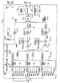
- numeral 1 indicates a condition responsive sense element in the form of a bridge described above. Although described as being responsive to pressure, it could also be used to sense other conditions such as acceleration, torque and force suitable for such bridge structures.
- ASIC application specific integrated circuit
- MSC is formed with first, second and third 8 to1 analog multiplexers 10a, 10b, 10c respectively at its front end.
- Multiplexer 10a has eight address positions IPO-IP7;
- multiplexer 10b has eight address positions IMO-IM7 and
- multiplexer 10c has address positions GD0-GD7.
- Each sense element bridge has a bridge node BRG, ground node GND, a plus output node INP and a minus output node INM.
- Sense element 1 has its plus output node connected to IP1 of multiplexer 10a, its minus output node connected to IM1 and its ground node GND connected to GD1 of multiplexer 10c.
- the other sense elements are similarly connected to ASIC 10 as shown in Fig. 1.
- the bridge voltage node of each sense element is connected to a voltage source V pwr through an electronically programmable low temperature coefficient bias resistor 10d1 through node BRG.
- Electronically programmable bias resistor 10d1 is controlled by register R REG, a digitally controlled variable to adjust the bias resistor connected to a selected sense element bridge that has a relatively high temperature coefficient in order to derive a temperature signal. It should be understood that in some applications the bridges could be biased with a zero valued resistor; however, in the present application a signal proportional to temperature signal is used for circuit compensation of temperature errors.
- the specific resistance level to correctly bias each bridge is selected at the time of calibration along with offset and gain to be discussed.
- the bridge voltage V brg is also fed through amplifiers 10d2 to analog to digital converter 10g to be discussed.
- Multiplexers 10a, 10b and 10c are controlled by respective registers MIP REG, MIM REG and MGD REG.
- a sense element is conditioned by setting each multiplexer to the same address position tying the selected sense element bridge ground node to signal ground to complete the bias of the sense element bridge.
- the plus and minus outputs are multiplexed into a common signal conditioning circuit path 10f.
- a command is issued by logic control section 10e which synchronizes the control of the various ASIC components.
- the command calls out of non-volatile memory section 10h and routes all the register values corresponding to the selected sense element bridge to all locations.
- the signal conditioning circuit path 10f is used to condition the sensed parameter, in the particular preferred embodiment, pressure.
- the sense element bridge plus and minus outputs are first fed into a differential gain amplifier 10F1 with the amplifier output connected to an offset correction stage comprising a summing network 10f2 controlled by register B REG to provide an offset correction proportional to voltage V brg which is added to the signal to correct for initial sense element offset error.
- the offset corrected signal proportional to pressure is then fed to a gain stage comprising a variable gain amplifier 10f3 controlled by register G REG with the resulting conditioned signal then connected to analog to digital converter 10g.
- Low pass filtering LPF is optionally provided as shown at the input to differential amplifier 10f1 to attenuate inputted noise and at the output of variable gain amplifier 10f3 to customize the pressure response to the system requirements.
- Analog to digital converter 10g then converts all the information related to the selected sense element into a digital word and transmits the information through digital port 10k to system controller 12 shown in Fig. 1.
- This information has offset and gain correction but no thermal correction in order to simplify the ASIC and reduce cost.
- data needed for providing thermal compensation is stored in non-volatile memory section 10h which is down loaded to system controller 12 upon command enabling controller 12 to make mathematical corrections for the signal.
- sense element plus and minus outputs are also multiplexed into sense element diagnostic circuit path 10m being summed into a summing node 10m1 with the summed signal connected to an offset correction stage comprising a summing network 10m2 proportional to the bridge drive V brg and controlled by register CB REG.
- the offset corrected signal is then fed to a variable gain stage 10m3 controlled by register CG REG.
- a low pass filter LPF preferably is used to tune the response of the circuit and the signal is inputted to analog to digital converter 10k.
- This provides the average of the sense element plus and minus outputs providing information which is independent of the input parameters of temperature and pressure to enable the system controller (12) to analyze this information and determine whether there are any sense elements or sense element connection faults, wherein the diagnostic signal varies beyond a certain boundary.
- a second diagnostic tool is provided by fixed test bridges RB1 and RB2 which are formed in the ASIC itself and are adapted to simulate one condition, e.g., zero pressure, and a second condition, e.g., full scale pressure, respectively.
- the register values of register R REG are selected for bridges RB1, RB2 so that when address 0 for test bridge RB1 is chosen or address 7 for test bridge RB2, the respective bridges are multiplexed through the sense element conditioning circuit path 10f temperature circuit path and the sense element diagnostic circuit path with the appropriate register values.
- Characterization data also stored at the time of manufacture, enable the system controller (12) to analyze this information and determine whether there are any faults in the ASIC.
- the test bridges provide a fixed input that does not vary over time, temperature or other parameter and which allows the analysis to determine whether the temperature pressure and sense element diagnostic circuits are functioning properly at both extremities of the condition, e.g., pressure range.
- each sense element has a set of register values stored to enable custom offset, gain, bridge drive and common mode signals so that any variation in such information will be applied to each selected sense element.
- This characterization data of the temperature and pressure matrix is stored in non-volatile memory section 10h.
- This information enables the system controller to respond to the specific performance of each sense element and perform appropriate mathematical compensation by means, for example, of a look-up table or polynomial coefficient correction to provide high accuracy compensation.
- the registers are originally set at two pressures and one temperature to calibrate the sense elements and this calibration then enables characterization at additional temperature and pressure points.
- Characterization refers to obtaining outputs for these additional temperature and pressure points and storing this data in table form or indirectly as polynomial coefficients without changing or adjusting the original calibration data. This provides a complete matrix of data required to mathematically fully correct the output signals in the system controller.
- Digital port 10k is used to transfer digital information to or from system controller 12.
- the digital port receives commands from the system controller 12 which are suitably verified by logic control 10e, as by conventional parity checks, decoded by the logic control section and performs the necessary function, e.g., select the addresses of the multiplexes, recall the appropriate register settings from non-volatile memory section 10h, initiate analog to digital conversion and then transmission of that data out of digital port 10k to system controller 12.
- the command can be issued individually to obtain and transmit a single piece of information, e.g., a pressure condition at a specified sense element, a diagnostic signal or other selected information or it could continually issue commands through a selected sequence obtaining data from each of the sense elements and diagnostics, as desired.
- the circuit on the ASIC is preferably formed so that data is obtained within a period of time which is short enough that whether the signal is already fully conditioned, i.e., temperature and pressure compensated and multiplexed by the system controller when a piece of information is called for in accordance with the prior art or partially conditioned with the compensation completed within the system controller in accordance with the invention is equivalent, for example, within a fraction of a millisecond.
- analog conditioning is effected in the sensor system, i.e., the ASIC providing a signal which is digitized and then compensation of the signal is completed in a host controller with information provided to volatile memory of the host controller from non-volatile memory of the ASIC.
- a plurality of sensors are multiplexed to a common electrically calibratible temperature, pressure and diagnostic signal conditioning path performing partial compensation of sense element errors which is transmitted to a host controller along with data coefficients enabling the host controller to digitally compensate for each of the sense elements.
- the test bridges and sense element diagnostic circuit path provide a continuing ability to ensure reliable operation.
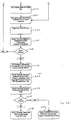
- the initialization sequence for transferal of characterization data from the ASIC MSC to the system controller is shown in Figs. 3a, 3b and includes application of power at 100, sending a command to transfer a specific piece of factory stored characterization data at step 102, transmission verification at step 104 and a decision step 106 to see if an error is detected.
- a negative decision leads to step 108 of decoding the command and controlling other circuit blocks to execute the command and then to step 110 for a parity check and to decision step 112 to see if an error is detected.
- a negative response leads to step 114 of loading the requested information into the digital port and then to step 116 adding transmission verification data and step 118 of transmitting the data.
- a positive response for decision blocks 104 and 112 lead to step 120 in which the error bit is loaded into the digital port.
- step 118 Following transmission of the data (step 118) the routine goes to step 122 in which the system controller digital port receives and verifies the transmission and then to decision step 124 to see if an error is detected. If no error is detected, the routine proceeds to process step 126 in which the data is stored in system controller memory and then to step 130 which goes to step 102 repeating the whole routine until all the characterization data is transferred from the ASIC MSC to the system controller. A positive decision of decision block 124 is also routed back to step 102.
- step 150 the system controller sends a command to transmit sense element data for element SE1 and at step 152 the digital port receives and verifies the transmission.
- Decision step 154 determines if an error is detected and upon a negative decision, the routine proceeds to step 156 in which the logic block decodes the command and controls other circuit blocks to execute the command and process step 158 performing a parity check and another error detect decision block 160.
- a negative response leads to step 162 transferring circuit calibration data associated with the sense element from non-volatile memory to the various registers and then to step 164 setting the address of the analog multiplexers.
- a time delay is provided to step 166 to allow the circuit to stabilize and then at step 168, analog to digital conversion of pressure, temperature and sense element SE1 diagnostic signal is effected.
- the ADC values are loaded into the digital port in step 170 and at step 172 the logic block adds transmission bits to data in the digital port. Going back to decision step 154 and 160, positive decisions lead to step 174 in which the detected error bit is loaded into the digital port. Process steps 172 and 174 lead to step 176 in which the digital port transfers the data and on to step 178 in which the system controller digital port receives and verifies the transmission.
- decision step 180 checks whether an error is detected, a positive response directing the routine back to the beginning step 150 and a negative response leading to step 182 storing the SE1 pressure, temperature and diagnostic data in the system controller memory.
- the system controller uses the stored characterization data to mathematically correct the pressure, temperature and diagnostic data of sense element SE1 and then at step 186 the system controller compares the corrected diagnostic data of sense element SE1 to fault thresholds.
- Decision block 190 checks to see if a fault is detected, a negative response leads to step 192 in which the system controller uses the corrected sense element SE1 pressure and temperature data in a control algorithm and a positive response results in the data not being used in the algorithm and the system controller reporting the error.
- Figs. 5a, 5b show the diagnostic data acquisition sequence for one of the tests or reference bridges, RB1.
- the sequence begins at step 200 when the system controller sends a command to the ASIC MSC to transmit bridge RB1 data and then proceeds to step 202 in which the digital port of the ASIC receives and verifies the transmission followed by error detection step 204.
- a negative response leads to step 206 in which the logic block decodes the command and controls other circuit blocks to execute the command and then to step 208 performing a parity check to verify the contents.
- a negative response of error detection step 210 leads to step 212 in which circuit calibration data associated with bridge RB1 is transferred from non-volatile memory to the appropriate registers and then to step 214 to set the analog multiplexers address.
- Step 216 provides a time delay to allow the circuit to stabilize and then the pressure, temperature and sense element diagnostic signal is converted from analog to digital format at step 218.
- the conversion values are loaded into the digital port at step 220 and at step 222 the logic block adds transmission verification to the data in the digital port. Going back to error detection steps 204 and 210, a detected error leads to step 224 in which the error bit is loaded into the digital port and then to step 222 where verification bits are added.
- Step 222 then proceeds to step 226 in which the digital port transmits the data and then to step 228 in which the digital port of the system controller receives and verifies the transmission.
- a detected error results in the routine cycling back to the beginning step 200 and if there is no detected error the routine goes on to step 232 in which the pressure, temperature and diagnostic data of bridge RB1 is stored in the system controller memory. Then the system controller calculates at step 234 the differences between bridge RB1 measured data and the corresponding bridge RB1 characterization data. At process step 236 the system controller compares the differences to allowed error limits and checks to see if an error is detected at step 238. A negative decision leads to step 240 in which the system controller determines that the ASIC has passed the diagnostic check while a positive decision leads to step 242 in which the system controller determines an error has occurred and reports the error.
Landscapes
- Physics & Mathematics (AREA)
- General Physics & Mathematics (AREA)
- Measuring Fluid Pressure (AREA)
- Testing Or Calibration Of Command Recording Devices (AREA)
Abstract
Description
- Provides an offset corrected and amplified signal proportional to the addition of the selected bridge output signals. Ideally, the output of the sense element diagnostic circuit is independent of pressure and temperature and, therefore, changes in this parameter can be used to indicate sense element failures (e.g., bridge parameter drift or hard failure). System comparison of the compensated output, with the value stored at the time of manufacture, is performed to determine if the sense element performance has degraded. Due to manufacturing tolerances, there will be a pressure and temperature dependence, which will reduce the accuracy of the sense element diagnostic signal and reduce system level error detection capability. System use of the pressure and temperature signal from the selected bridge provide a means of correcting pressure and temperature related sense element diagnostic signal errors allowing for more accurate analysis and finer error detection capability.
A digital port function is provided to transmit data to and receive data from the host or system controller. The system controller inputs a command to the conditioning electronics, which in turn, performs the function requested by the controller. For example, the controller may request pressure information from
Claims (23)
- A condition responsive sense element system comprising:a plurality of condition responsive sense elements having outputs,an electronic circuit having at least one multiplexer with addressable inputs connected to the sense elements outputs, the at least one multiplexer having an output connected to a signal conditioning circuit path, the signal conditioning circuit path having signal conditioning components, nonvolatile memory for storing calibration and characterisation data for each of the sense elements and the electronic circuit and a data port for transmitting data from the nonvolatile memory to the multiplexers and to the signal conditioning components for each sense element addressed for conditioning the signals for each sense element and to an external controller to enable the external controller to perform mathematical corrections of the conditioned signal.
- A condition responsive sense element system according to claim 1 in which the sense elements each comprises a bridge network, each bridge network having a bridge voltage node, a ground node, a plus output node and a minus output node and further comprising an electronically programmable resistor connected in series between a voltage source and each respective bridge voltage node for providing a selected bias to each respective sense node.
- A condition responsive sense element system according to claim 1 or 2 further comprising first and second non-condition responsive sense element test bridge networks formed in the electronic circuit, the test bridge networks each having a bridge voltage node, a ground node, a plus output node and a minus output node, the test bridge networks enabling the diagnoses of sense element bias faults.
- A condition responsive sense element system according to claim 1 or 2 further comprising first and second non-condition responsive test bridge networks formed in the electronic circuit, the test bridge networks each having a bridge voltage node, a ground node, a plus output node and a minus output node, the output nodes connected through a multiplexer to the signal conditioning circuit path, the plus and minus outputs of the first test bridge providing signals of a first value, the plus and minus outputs of the second test bridge providing signals of a second value, the test bridge network providing data for diagnosing electronic circuit faults.
- A condition responsive sense element system according to any one of the preceding claims in which the electronic circuit is an ASIC.
- A condition responsive sense element system according to any one of the preceding claims further comprising a sense element diagnostic circuit path including a summing circuit and conditioning components, plus and minus outputs of an addressed sense element being connected to the summing circuit and being summed with the summed value fed to the conditioning components of the sense element diagnostic circuit path to provide a diagnostic signal, the stored calibration and characterisation data for each of the sense elements and diagnostic circuit path transmitted to the external controller for enabling the external controller to perform mathematical corrections of the diagnostic signal.
- A condition responsive sense element system according to claim 6 further comprising first and second non-condition responsive sense element test bridge networks formed in the electronic circuit, the test bridge networks each having a bridge voltage node, a ground node, a plus output node and a minus output node, the output nodes connected to the diagnostic circuit path through a multiplexer, the plus and minus outputs of the first test bridge network providing signals of a first value, the plus and minus outputs of the second test bridge network providing signals of a second value, the test bridge networks providing data for diagnosing diagnostic circuit path faults.
- A condition responsive sense element system according to any one of the preceding claims in which the condition being sensed is one of pressure, acceleration, force and torque.
- A condition responsive sense element system according to any one of the preceding claims in which the condition being sensed is pressure.
- A condition responsive sense element system comprising:a plurality of condition responsive sense elements providing a voltage output dependent on the condition, the sense elements each having a bridge network with a bridge voltage node, a ground node, a plus output node and a minus output node,a voltage source,each bridge voltage node connected to the voltage source,an electronic circuit having first, second and third multiplexers, each having an output and a plurality of address input positions, the plus node of each sense element connected to a respective multiplexer address position of the first multiplexer, the minus node of each sense element connected to a respective multiplexer address position of the second multiplexer and the ground node of each sense element connected to a respective address position of the third multiplexer, a respective register connected to each multiplexer,a signal ground, the output of the third multiplexer connected to a signal ground,a signal conditioning circuit path, the signal conditioning circuit path comprising a differential amplifier having a plus and a minus input and an output, the output of the first multiplexer connected to the plus input of the differential amplifier, the output of the second multiplexer connected to the minus input of the differential amplifier, an offset correction network having a summing circuit with an output and inputs, the input connected to the output of the differential amplifier and an offset circuit controlled by a register to provide a correction proportional to bridge voltage, and a gain correction network having a variable gain amplifier having an input connected to the output of the offset correction network and controlled by a gain correction register,a digital port,an analog to digital converter having an input and an output, the output of the gain correction network inputted to the analog to digital converter to provide a digital signal corresponding to the sensed condition to the digital port,a logic control and a nonvolatile memory section, the nonvolatile memory section being connected to the several registers under the control of the logic control, the digital port forming an interface for transmitting data to and receiving data from an external controller, the nonvolatile memory providing data to the external controller enabling the external controller to perform mathematical error correction for the condition sensor signals and the logic control providing commands for obtaining sense element data from a selected sense element.
- A condition responsive sense element system according to claim 10 further comprising an electronically programmable resistor connected in series between the voltage source and each respective bridge voltage node for providing a selected bias to each respective sense element when selected and a register for receiving data from nonvolatile memory connected to the electronically programmable resistor to control the value of the resistor.
- A condition responsive sense element system according to claim 10 or 11 further comprising first and second non-condition responsive test bridge networks formed in the electronic circuit, each test bridge network having a bridge voltage node, a ground node, a plus output node and a minus output node, the test bridge networks enabling the diagnoses of sense element bias faults.
- A condition responsive sense element system according to claim 10 or 11 further comprising first and second non-condition responsive test bridge networks formed in the electronic circuit, each test bridge network having a bridge voltage node, a ground node, a plus output node and a minus output node, the output nodes and the ground nodes connected respectively to the signal conditioning circuit path and a signal ground through a multiplexer, the plus and the minus output nodes of the first test bridge network providing signals of a first value, the plus and minus output nodes of the second test bridge network providing signals of a second value, the test bridge networks providing data for diagnosing electronic circuit faults.
- A condition responsive sense element system according to any one of claims 10 to 13 in which the electronic circuit is an ASIC.
- A condition responsive sense element system according to any one of claims 10 to 14 further comprising a sense element diagnostic circuit path including a summing circuit and conditioning components, plus and minus outputs of an addressed sense element being connected to the summing circuit and being summed with the summed value fed to the conditioning components of the sense element diagnostic circuit path to provide a diagnostic signal, the stored calibration and characterisation data for each of the sense elements and diagnostic circuit path transmitted to the external controller for enabling the external controller to perform mathematical corrections of the diagnostic signal.
- A condition responsive sense element system according to claim 15 comprising first and second non-condition responsive sense element test bridge networks formed in the electronic circuit, the test bridge networks each having a bridge voltage node, a ground node, a plus output node and a minus output node, the output nodes connected respectively to the diagnostic circuit path and a signal ground through a multiplexer, the plus and minus outputs of the first test bridge network providing signals of a first value, the plus and minus outputs of the second test bridge network providing signals of a second value, the test bridge networks providing data for diagnosing diagnostic circuit path faults.
- A condition responsive sense element system according to any one of claims 10 to 16 in which the condition is one of pressure, acceleration, torque and force.
- A condition responsive sense element system according to any one of claims 10 to 17 in which the condition is pressure.
- A method of condition sensing in a condition responsive sensing system having a plurality of condition sense bridge elements, the method comprising the steps of:providing a bias for each sense element,providing an electronic circuit having multiplexers, a signal conditioning circuit path having signal conditioning components, an analog to digital converter, logic control, nonvolatile memory and a digital port for transmitting and receiving data,obtaining electronic calibration data for each sense element during manufacture of the system and storing that information in nonvolatile memory,connecting the electronic controller to an external controller,transmitting data from nonvolatile memory to enable the external controller to perform mathematical corrections to a conditioned digital signal,selecting an address of the multiplexers for connecting outputs of a selected bridge sense element to the signal conditioning circuit path and to transmit basic offset and gain calibration data to the signal conditioning components in the signal conditioning path,partially conditioning the addressed sense element using the basic offset and gain calibration data transmitted from nonvolatile memory, to provide a partially conditioned signal,converting the partially conditioned signal from an analog format to a digital format in the analog to digital converter to provide a digital signal,transmitting the digital signal to the external controller andcompleting the conditioning of the partially conditioned signal by performing mathematical corrections to the digital signal in the external controller using the data transferred from the nonvolatile memory.
- A method according to claim 19 further comprising the steps of:forming a first non-condition responsive test bridge in the electronic circuit, the first bridge providing a first reference value, andforming a second non-condition responsive test bridge in the electronic circuit, the second bridge providing a second reference value, the data from the first and second test bridges providing reference data for diagnostic use of electronic circuit faults.
- A method according to claim 19 or 20 further comprising the steps of:forming a sense element diagnostic circuit path in the electronic circuit including a summing circuit for summing the plus and minus outputs of the selected sense element and offset and gain components corresponding to the offset and gain correction networks of the signal conditioning circuit path to provide reference data for diagnostic use of sense element and sense element connection faults.
- A method according to any one of claims 19 to 21 in which the electronic circuit faults includes faults in the sense element bias.
- A method according to any one of claims 19 to 22 further comprising the step of forming the electronic circuit as an ASIC.
Applications Claiming Priority (4)
| Application Number | Priority Date | Filing Date | Title |
|---|---|---|---|
| US26447301P | 2001-01-26 | 2001-01-26 | |
| US264473P | 2001-01-26 | ||
| US36719P | 2001-12-21 | ||
| US10/036,719 US6687642B2 (en) | 2001-01-26 | 2001-12-21 | Condition responsive sense system and method |
Publications (3)
| Publication Number | Publication Date |
|---|---|
| EP1235053A2 true EP1235053A2 (en) | 2002-08-28 |
| EP1235053A3 EP1235053A3 (en) | 2004-07-21 |
| EP1235053B1 EP1235053B1 (en) | 2007-07-25 |
Family
ID=26713432
Family Applications (1)
| Application Number | Title | Priority Date | Filing Date |
|---|---|---|---|
| EP02250475A Expired - Lifetime EP1235053B1 (en) | 2001-01-26 | 2002-01-24 | Apparatus and method for collecting and processing data from a plurality of sensors |
Country Status (2)
| Country | Link |
|---|---|
| US (1) | US6687642B2 (en) |
| EP (1) | EP1235053B1 (en) |
Cited By (2)
| Publication number | Priority date | Publication date | Assignee | Title |
|---|---|---|---|---|
| EP1548417A1 (en) | 2003-12-22 | 2005-06-29 | Texas Instruments Incorporated | Sensor system for and method of measuring variable physical quantities |
| US12013259B2 (en) | 2018-09-26 | 2024-06-18 | Infineon Technologies Ag | Providing compensation parameters for sensor integrated circuits |
Families Citing this family (21)
| Publication number | Priority date | Publication date | Assignee | Title |
|---|---|---|---|---|
| DE10254391B4 (en) * | 2002-11-21 | 2016-05-12 | Dr. Johannes Heidenhain Gmbh | Circuit arrangement and equipped with this circuit arrangement angle or length measuring device |
| US7668512B2 (en) * | 2003-01-15 | 2010-02-23 | Avago Technologies Fiber Ip (Singapore) Pte. Ltd. | Transceiver with a test mode of operation |
| US7007552B2 (en) | 2004-07-26 | 2006-03-07 | Texas Instruments Incorporated | Multi-channel pressure sensing apparatus |
| SG120999A1 (en) * | 2004-09-15 | 2006-04-26 | Oki Techno Ct Singapore Pte | Automatic gain control system and method |
| US7486996B2 (en) * | 2005-09-26 | 2009-02-03 | Eaton Corporation | Transmission control unit having pressure transducer package |
| US7383735B2 (en) * | 2005-09-26 | 2008-06-10 | Eaton Corporation | Pressure transducer package for a manifold |
| US8175835B2 (en) * | 2006-05-17 | 2012-05-08 | Honeywell International Inc. | Flow sensor with conditioning-coefficient memory |
| US8010322B2 (en) | 2006-05-17 | 2011-08-30 | Honeywell International Inc. | Signal conditioning IC with conditioning-coefficient memory |
| US7631228B2 (en) * | 2006-09-12 | 2009-12-08 | International Business Machines Corporation | Using bit errors from memory to alter memory command stream |
| US7509221B2 (en) * | 2007-01-17 | 2009-03-24 | Caterpillar Inc. | Custom configuration strategy for on-package genset controllers |
| US8718981B2 (en) | 2011-05-09 | 2014-05-06 | Honeywell International Inc. | Modular sensor assembly including removable sensing module |
| US9342695B2 (en) * | 2012-10-02 | 2016-05-17 | Mordecai Barkan | Secured automated or semi-automated systems |
| US11188652B2 (en) | 2012-10-02 | 2021-11-30 | Mordecai Barkan | Access management and credential protection |
| JP5900536B2 (en) | 2013-09-30 | 2016-04-06 | 株式会社デンソー | Sensor signal detection device |
| CN103954315B (en) * | 2014-04-25 | 2017-01-04 | 西安航空动力股份有限公司 | Data collecting system online test method |
| CN106527390A (en) * | 2015-09-11 | 2017-03-22 | 九江长江仪表精密液压件厂 | Fault detection and diagnosis method for smart electrohydraulic actuator |
| HUE058966T2 (en) * | 2017-12-15 | 2022-10-28 | Kistler Holding Ag | Wim sensor and method for manufacturing the wim sensor |
| US10782157B2 (en) | 2018-06-26 | 2020-09-22 | Faurecia Automotive Seating, Llc | Analog signal conditioning with diagnostics for capacitive sensor elements |
| CN209326840U (en) | 2018-12-27 | 2019-08-30 | 热敏碟公司 | Pressure sensor and pressure transmitter |
| US11965790B2 (en) * | 2020-07-03 | 2024-04-23 | Honeywell International Inc. | Sensor diagnostic method and system for pressure transmitter |
| US20260074704A1 (en) * | 2024-09-09 | 2026-03-12 | National Instruments Corporation | Simultaneously Sampled Data Acquisition Device |
Family Cites Families (8)
| Publication number | Priority date | Publication date | Assignee | Title |
|---|---|---|---|---|
| JPS57111421A (en) * | 1980-12-29 | 1982-07-10 | Fuji Photo Film Co Ltd | Measuring device of multielement sensor |
| US4399515A (en) * | 1981-03-31 | 1983-08-16 | The United States Of America As Represented By The Administrator Of The National Aeronautics And Space Administration | Self-correcting electronically scanned pressure sensor |
| USH81H (en) * | 1984-09-24 | 1986-07-01 | The United States Of America As Represented By The Secretary Of The Army | Projectile guidance recording system |
| US5005142A (en) * | 1987-01-30 | 1991-04-02 | Westinghouse Electric Corp. | Smart sensor system for diagnostic monitoring |
| US5014238A (en) * | 1987-07-15 | 1991-05-07 | Distributed Matrix Controls Inc. | Universal input/output device |
| US5068811A (en) * | 1990-07-27 | 1991-11-26 | Bha Group, Inc. | Electrical control system for electrostatic precipitator |
| US5095453A (en) * | 1990-11-13 | 1992-03-10 | Johnson Service Company | Sensor monitoring arrangement with error correction |
| DE4405607A1 (en) * | 1994-02-22 | 1995-08-24 | Hey Tec Regelungstechn Gmbh | Measurement and conversion circuit for different physical quantities |
-
2001
- 2001-12-21 US US10/036,719 patent/US6687642B2/en not_active Expired - Lifetime
-
2002
- 2002-01-24 EP EP02250475A patent/EP1235053B1/en not_active Expired - Lifetime
Cited By (3)
| Publication number | Priority date | Publication date | Assignee | Title |
|---|---|---|---|---|
| EP1548417A1 (en) | 2003-12-22 | 2005-06-29 | Texas Instruments Incorporated | Sensor system for and method of measuring variable physical quantities |
| US7031863B2 (en) | 2003-12-22 | 2006-04-18 | Texas Instruments Incorporated | Variable condition responsive sense system and method |
| US12013259B2 (en) | 2018-09-26 | 2024-06-18 | Infineon Technologies Ag | Providing compensation parameters for sensor integrated circuits |
Also Published As
| Publication number | Publication date |
|---|---|
| US20020103613A1 (en) | 2002-08-01 |
| EP1235053A3 (en) | 2004-07-21 |
| EP1235053B1 (en) | 2007-07-25 |
| US6687642B2 (en) | 2004-02-03 |
Similar Documents
| Publication | Publication Date | Title |
|---|---|---|
| EP1235053B1 (en) | Apparatus and method for collecting and processing data from a plurality of sensors | |
| JP5173115B2 (en) | Field transmitter with diagnostic self-test mode | |
| US6519546B1 (en) | Auto correcting temperature transmitter with resistance based sensor | |
| US6450005B1 (en) | Method and apparatus for the calibration and compensation of sensors | |
| US7031863B2 (en) | Variable condition responsive sense system and method | |
| EP0980601B1 (en) | Signal conditioning circuit including a combined adc/dac, sensor system, and method therefor | |
| EP1111344B1 (en) | Sensor fault detection method and apparatus | |
| US6996488B2 (en) | Sensor signal conditioner | |
| EP1825241B1 (en) | Method and apparatus for storing vacuum gauge calibration parameters and measurement data on a vacuum gauge structure | |
| CN112834974B (en) | Method for testing battery sensor, and battery sensor | |
| GB2296328A (en) | Vehicle load measuring systems | |
| US6035721A (en) | Process for compensating for the incorrect operation of measuring devices caused by external influences | |
| JP4936337B2 (en) | Status response detection system and method | |
| JPH0243236B2 (en) | ||
| US6765391B2 (en) | Low cost asic architecture for safety critical applications monitoring an applied stimulus | |
| KR102013644B1 (en) | Error reduction device for automatic calibrator of sensor acquisition instrument | |
| US6053050A (en) | Signal conditioning system | |
| EP4707761A1 (en) | Pressure sensor, method, brake system, vehicle and use of a pressure sensor | |
| US5798692A (en) | Digital compensation circuit for calibration of sensors | |
| KR101377531B1 (en) | The moudule of smart pressure sensor | |
| JP4179214B2 (en) | Sensor temperature characteristics inspection method | |
| DE60221305T2 (en) | Apparatus and method for collecting and processing data from multiple sensors | |
| JP2541438B2 (en) | Signal input circuit | |
| JP2536821B2 (en) | Self-diagnosis circuit | |
| KR102035924B1 (en) | Pressure sensor having bridge structure integrated with breakwon diagnosis circuit and breakdown diagnosis method thereof |
Legal Events
| Date | Code | Title | Description |
|---|---|---|---|
| PUAI | Public reference made under article 153(3) epc to a published international application that has entered the european phase |
Free format text: ORIGINAL CODE: 0009012 |
|
| AK | Designated contracting states |
Kind code of ref document: A2 Designated state(s): AT BE CH CY DE DK ES FI FR GB GR IE IT LI LU MC NL PT SE TR |
|
| AX | Request for extension of the european patent |
Free format text: AL;LT;LV;MK;RO;SI |
|
| PUAL | Search report despatched |
Free format text: ORIGINAL CODE: 0009013 |
|
| AK | Designated contracting states |
Kind code of ref document: A3 Designated state(s): AT BE CH CY DE DK ES FI FR GB GR IE IT LI LU MC NL PT SE TR |
|
| AX | Request for extension of the european patent |
Extension state: AL LT LV MK RO SI |
|
| RIC1 | Information provided on ipc code assigned before grant |
Ipc: 7G 01D 3/00 A Ipc: 7G 01R 17/10 B Ipc: 7G 01D 3/02 B |
|
| 17P | Request for examination filed |
Effective date: 20040903 |
|
| AKX | Designation fees paid |
Designated state(s): DE FR GB |
|
| 17Q | First examination report despatched |
Effective date: 20050411 |
|
| GRAP | Despatch of communication of intention to grant a patent |
Free format text: ORIGINAL CODE: EPIDOSNIGR1 |
|
| RAP1 | Party data changed (applicant data changed or rights of an application transferred) |
Owner name: SENSATA TECHNOLOGIES, INC. |
|
| GRAS | Grant fee paid |
Free format text: ORIGINAL CODE: EPIDOSNIGR3 |
|
| GRAA | (expected) grant |
Free format text: ORIGINAL CODE: 0009210 |
|
| AK | Designated contracting states |
Kind code of ref document: B1 Designated state(s): DE FR GB |
|
| REG | Reference to a national code |
Ref country code: GB Ref legal event code: FG4D |
|
| REF | Corresponds to: |
Ref document number: 60221305 Country of ref document: DE Date of ref document: 20070906 Kind code of ref document: P |
|
| ET | Fr: translation filed | ||
| PLBE | No opposition filed within time limit |
Free format text: ORIGINAL CODE: 0009261 |
|
| STAA | Information on the status of an ep patent application or granted ep patent |
Free format text: STATUS: NO OPPOSITION FILED WITHIN TIME LIMIT |
|
| 26N | No opposition filed |
Effective date: 20080428 |
|
| PGFP | Annual fee paid to national office [announced via postgrant information from national office to epo] |
Ref country code: FR Payment date: 20120111 Year of fee payment: 11 |
|
| REG | Reference to a national code |
Ref country code: FR Ref legal event code: ST Effective date: 20130930 |
|
| PG25 | Lapsed in a contracting state [announced via postgrant information from national office to epo] |
Ref country code: FR Free format text: LAPSE BECAUSE OF NON-PAYMENT OF DUE FEES Effective date: 20130131 |
|
| PGFP | Annual fee paid to national office [announced via postgrant information from national office to epo] |
Ref country code: GB Payment date: 20141230 Year of fee payment: 14 |
|
| PGFP | Annual fee paid to national office [announced via postgrant information from national office to epo] |
Ref country code: DE Payment date: 20150126 Year of fee payment: 14 |
|
| REG | Reference to a national code |
Ref country code: DE Ref legal event code: R119 Ref document number: 60221305 Country of ref document: DE |
|
| GBPC | Gb: european patent ceased through non-payment of renewal fee |
Effective date: 20160124 |
|
| PG25 | Lapsed in a contracting state [announced via postgrant information from national office to epo] |
Ref country code: GB Free format text: LAPSE BECAUSE OF NON-PAYMENT OF DUE FEES Effective date: 20160124 Ref country code: DE Free format text: LAPSE BECAUSE OF NON-PAYMENT OF DUE FEES Effective date: 20160802 |