EP1235010B1 - Repositionable brush seal for turbomachinery - Google Patents
Repositionable brush seal for turbomachinery Download PDFInfo
- Publication number
- EP1235010B1 EP1235010B1 EP02251031A EP02251031A EP1235010B1 EP 1235010 B1 EP1235010 B1 EP 1235010B1 EP 02251031 A EP02251031 A EP 02251031A EP 02251031 A EP02251031 A EP 02251031A EP 1235010 B1 EP1235010 B1 EP 1235010B1
- Authority
- EP
- European Patent Office
- Prior art keywords
- brush seal
- component
- mounting member
- seal
- brush
- Prior art date
- Legal status (The legal status is an assumption and is not a legal conclusion. Google has not performed a legal analysis and makes no representation as to the accuracy of the status listed.)
- Expired - Lifetime
Links
Images


Classifications
-
- F—MECHANICAL ENGINEERING; LIGHTING; HEATING; WEAPONS; BLASTING
- F16—ENGINEERING ELEMENTS AND UNITS; GENERAL MEASURES FOR PRODUCING AND MAINTAINING EFFECTIVE FUNCTIONING OF MACHINES OR INSTALLATIONS; THERMAL INSULATION IN GENERAL
- F16J—PISTONS; CYLINDERS; SEALINGS
- F16J15/00—Sealings
- F16J15/16—Sealings between relatively-moving surfaces
- F16J15/32—Sealings between relatively-moving surfaces with elastic sealings, e.g. O-rings
- F16J15/3284—Sealings between relatively-moving surfaces with elastic sealings, e.g. O-rings characterised by their structure; Selection of materials
- F16J15/3288—Filamentary structures, e.g. brush seals
Description
- This invention relates to a brush seal for sealing between two components, e.g., a stationary component and a rotating component and, more particularly, relates to a brush seal whose position can be changed in two perpendicular directions relative to the components, e.g., radial and axial directions relative to fixed and rotating components.
- In turbomachinery, brush seals are typically installed in a fixed position on a stationary component. The turbomachinery comprises many individual components, such as wheels, buckets, nozzles, diaphragms, casings, bearings and the like, each with its own manufacturing tolerances. As a result, when clearances between stationary and rotating components are measured at final assembly, different and relatively large variations in clearances can be expected due to the accumulation of the component manufacturing tolerances. During operation of the turbomachinery, the clearances between the components may also change due to differences in thermal expansion and the effects of rotation. Brush seals must be designed to accommodate these variations in clearances and to prevent a "hard rub" condition wherein the brush seal backing plate contacts the rotating component. In applications in turbomachinery where the space allotted for the brush seal is very limited, it becomes very difficult, if not impossible, to accommodate all of the manufacturing tolerances and provide a sufficient clearance margin to avoid a hard rub with the current brush seal designs.
- Brush seals are currently mounted within a stationary component, typically a diaphragm, or nested within a labyrinth seal, using a T-shaped or L-shaped slot to establish the axial and radial position of the brush seal. Typically, the seal is repositionable only to the extent the position of the component carrying the brush seal, e.g., a diaphragm, is likewise repositionable. The position of the brush seal with respect to the carrier component is conventionally not repositionable. Accordingly, there is a need for a brush seal assembly which enables the position of the brush seal to be changed relative to its carrier component.
- According to the invention, there is provided a repositionable seal assembly for sealing between first and second components, comprising a brush seal for securement to the first component and having a plurality of bristles disposed between a pair of backing plates, said bristles arranged in a common plane and projecting from between said plates to terminate in bristle tips for sealing engagement with the second component; a mounting member carrying said brush seal for securing the brush seal to the first component; a first shim cooperable with and disposed between the first component and the mounting member for changing the position of the brush seal relative to the first component in a direction perpendicular to said plane; a second shim disposed between the first component and said mounting member for changing the position of the brush seal in a direction parallel to said plane; and at least one fastener for securing the brush seal to the first component in a changed position.
- In a preferred embodiment of the invention, a brush seal assembly is provided wherein the position of the brush seal can be changed relative to the carrier component in two directions generally perpendicular to one another. The brush seal typically includes a pair of backing plates and elongated bristles disposed between the backing plates and terminating in bristle tips spaced from margins of the backing plates for engagement with the rotating component. It is desirable to be able to reposition the brush seal in both axial and radial directions relative to the rotating component. To accomplish this, an annular or arcuately segmented brush seal is provided with a mounting member receivable within an axially opening slot or groove formed on the stationary component. By forming the slot or groove to a length exceeding the length of the mounting member and with the mounting member extending normal to the plane of the brush seal, the brush seal may be repositioned axially into the desired position. To change the position of the brush seal in a radial direction relative to the stationary and rotating member, shims are deployed on opposite sides of the mounting member and between the walls of the slot or groove. By varying the thicknesses of the shims between the brush seal and the slot or groove, the radial location of the brush seal is changed relative to the shaft. To fix the brush seal in the new position, two or more pins or screws may be used to secure the brush seal to the stationary component. In this embodiment, as well as other embodiments hereof, the seal may be repositioned in this manner as part of an original equipment manufacture or during a retrofit of the seal into the turbomachinery. Thus the turbomachinery may be delivered to an installation site with the stationary component having pre-drilled, undersized holes and the brush seal provided without pre-drilled holes. The final location of the holes on the brush seal is determined based on measurements at assembly. Pins or screws also provide an anti-rotation feature which prevents the brush seal from being displaced circumferentially relative to the fixed component.
- In another preferred embodiment of the invention, set screws are employed to change the position of the mounting member relative to the stationary component in a radial direction. Once the desired radial position is obtained, the screws can be staked to the brush seal to prevent further rotation, thus fixing the position of the brush seal. The axial position of the brush seal is repositioned by inserting a laminated shim pack into the slot or groove of the fixed component. This laminated shim pack may be formed of individual foils, for example 0,1 mm (.004 inches) thick, joined by an adhesive. By removing layers of the foil from the shim pack, the axial position of the brush seal relative to the fixed component can be accurately determined.
- Brush seals are typically applied in turbomachinery in arcuate segments whereby a plurality of segments form a complete annulus about the rotating component. In a further preferred embodiment of the invention, each segment is provided with an eccentric cam rotatable about an axis. The segment includes a cam follower positioned so that rotation of the cam causes the segment to be displaced in a radial direction, thereby repositioning the brush seal relative to the two components. At least a pair of eccentric cams are utilized for repositioning each segment.
- In a still further preferred embodiment of the invention, the brush seal radial and axial positions are set by shims. The brush seal segment is secured to the stationary or fixed component by radial socket head cap screws and retaining pins. The brush seal segment has slots machined to accept the socket head cap screws. Once the radial and axial position of the seal has been set, the cap screws can be tightened to secure the assembly. By tack-welding the screw heads to the brush seal, loosening of the screws is prevented. Additional strength to the assembly is provided by installing retaining pins through the mounting arm and fixed component.
- In another preferred embodiment of the invention, a repositionable seal assembly is provided for sealing between first and second components. This assembly comprises a brush seal for securement to the first component and having a plurality of bristles disposed between a pair of backing plates, the bristles arranged in a common plane and projecting from between the plates to terminate in bristle tips for sealing engagement with the second component, a mounting member carrying the brush seal for securing the brush seal to the first component, at least one shim cooperable between the first component and the mounting member for repositioning the brush seal relative to the first component in one of first and second directions, respectively generally perpendicular and parallel to the plane, and at least one fastener for securing the brush seal to the first component in a new position.
- In a further preferred embodiment of the invention, a seal assembly for a turbine comprises a first, generally annular component fixed against rotation, a second component rotatable about an axis, and a seal assembly between the first and second components including a brush seal carried by one of the first and second components. The brush seal includes a plurality of bristles carried by at least one mounting plate and projecting from the mounting plate to terminate in bristle tips for sealing engagement with another of the first and second components, and a mounting member for mounting the brush seal to one component. The seal assembly further includes at least one shim cooperable between one component and the mounting member to reposition the brush seal relative to one component in one of first and second directions, respectively generally perpendicular and parallel to the axis, and at least one fastener securing the brush seal and one component to one another in the new position.
- The invention will now be described in greater detail, by way of example, with reference to the drawings, in which:-
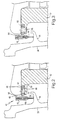
- FIGURE 1 is a fragmentary cross-sectional view of a segmented brush seal assembly in a finally changed position between stationary and rotary components in turbomachinery;
- FIGURE 2 is a view similar to Figure 1 illustrating a further embodiment of a repositioned brush seal assembly according to one embodiment of the invention;
- FIGURE 3 is a view similar to Figure 2 at a different circumferential location illustrating a pinned connection between the brush seal and the stationary component;
- FIGURE 4 is a view similar to Figure 1 illustrating a further embodiment of a repositionable brush seal assembly according to the invention;
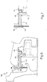
- FIGURE 5 is an enlarged front elevational view of an eccentric cam employed in the repositionable brush seal assembly of Figure 4;
- FIGURE 6 is a view similar to Figure 1 illustrating a further embodiment of the invention; and
- FIGURE 7 is a view of the brush seal segment of Figure 6 at a different circumferential location.
- Figure 1 illustrates a first fixed or stationary annular component, e.g., a
diaphragm 10, in turbomachinery surrounding a secondrotating component 12, e.g., a rotor, and a repositionable brush seal assembly, generally designated 14, for sealing between the first andsecond components Brush seal assembly 14 includes abrush seal 16 having a pair ofbacking plates bristles 22 extending between the backing plates.Bristles 22 are elongated, may be formed of a metal or ceramic material, and havetips 24 projecting from the radial margins ofbacking plates opposing sealing surface 26 ofrotor 12.Bristles 22 are disposed at a cant angle, preferably in the direction of rotation of the rotor, for example, a cant angle of approximately 30-40°. Where repositionablebrush seal assembly 14 is used in turbomachinery as illustrated,brush seal 16 is provided in a plurality of arcuate segments arranged in end-to-end relation relative to one another to form a complete annulus aboutrotor 12. - To reposition
brush seal assembly 14 relative to both components in axial and radial directions, i.e., directions perpendicular to one another,fixed component 10 is provided with a slot or agroove 30 which, while illustrated as a channel with opposed sides and a base wall, may comprise a recess having only a pair of sides as shown in Figure 4. To mountbrush seal assembly 14 to fixedcomponent 10,brush seal 16 includes amounting member 32 which, in a preferred form, projects in an axial direction and conforms to the arcuate configuration of the brush seal and slot orgroove 30. Consequently, by insertingmounting member 32 into slot orgroove 30, the axial position of the brush seal can be altered relative tofixed component 10 until the desired axial dimension relative torotor 12 is obtained. To reposition the radial position ofbrush seal 16,arcuate shims 34 are provided on opposite sides of mountingmember 32. By varying the thickness of the shims betweenmounting member 32 and the side walls of slot orgroove 30, the radial position ofbrush seal 16 relative to both components can be changed.Shims 34 may extend the full length of the arcuate segment or be provided in discrete arcuate lengths at discrete positions along slot orgroove 30. - To fix
brush seal 16 in the new position, fasteners, which may be in the form of pins or screws, such aspin 36, may be employed to secure mountingmember 32 to fixedcomponent 10. Two or more such fasteners may be used, depending upon the circumferential length of the arcuate seal segment. - The brush seal may be repositioned upon initial manufacture or as a retrofit. For example, as a retrofit, a diaphragm may be delivered to the installation site with pre-drilled and undersized holes. The brush seal may be provided without pre-drilled holes, with the final location of the holes for final securement of the brush seal to
component 10 being determined based on measurements at the assembly site. Pins or screws 36 provide an anti-rotation feature which prevents the seal from circumferential displacement relative to fixedcomponent 10. - In the embodiment illustrated in Figures 2 and 3, a brush seal assembly, generally designated 40, includes a
brush seal 42 havingbristles 44 disposed between a pair ofplates member 50 for supporting the brush seal from a fixed orstationary component 52 with the tips 54 of the brush seal engaging thewings 56 of abucket 58. In this embodiment, the mounting member is provided with at least a pair ofset screws 60 at circumferentially spaced positions about the seal segment and threaded to mountingmember 50. By appropriately positioning the set screws, i.e., threading the set screws in mountingmember 50, the radial position of the brush seal is set. The screws can then be staked to brushseal mounting member 50 to prevent further rotation. The axial position of the seal is repositioned by inserting an arcuate laminatedfoil shim pack 62 into the slot orgroove 64. By removing adhesively attached foil layers of the shim pack, the thickness of the shim pack can be reduced to accurately locate the brush seal in the axial direction. Once the appropriate radial and axial positions of the brush seal have been identified, a secondlaminated shim pack 66 may be disposed between opposite sides of mountingmember 50 and the sides ofgroove 64. As illustrated in Figure 3, two or moreradial pins 68 may be disposed in openings throughstationary component 52 and mountingarm 50 to finally securebrush seal assembly 40 tostationary component 52. - Figures 4 and 5 illustrate a further preferred embodiment of the brush seal assembly of the invention. The brush seal assembly, generally designated 70, includes a
brush seal 72 having a plurality ofbristles 74, as in the preceding embodiments, disposed between abacking plate 76 and the front face of anarcuate angle element 78 which includes a generally radially extendingarcuate leg 80. At two or more locations along the circumferential extent ofleg 80,eccentric cams 82 are provided. Eacheccentric cam 82 has an off-center opening 84 which receives thehead 86 of aconnection 88 fastened to thestationary component 90 by, for example, screw threads. Eachopening 92 inleg 80 serves as a cam follower for radially positioningbrush seal 72. For example, by rotating eccentricallymounted cam 82 about the axis ofhead 86, which axis may be parallel to the rotor axis of rotation, the radial position ofbrush seal 72 is altered. Once the desired radial distance is obtained,cam 82 may be secured toleg 80 by, for example, peening along the surface ofleg 80, as illustrated in Figure 5. Axial positioning ofbrush seal 72 is accomplished as in the prior embodiments by locating ashim pack 94 between fixedcomponent 90 and the back side ofleg 80. By peeling fromshim pack 94 an appropriate number of foil layers, the brush seal is located in the desired axial position. - In Figures 6 and 7, a brush seal assembly, generally designated 100, includes a
brush seal 102 having a plurality ofbristles 104 as in the preceding embodiments, withbacking plates member 110 for mountingbrush seal assembly 100 on astationary component 112. In this embodiment, the brush seal radial and axial positions are set byshims stationary component 112 by two or more radial socket head cap screws 118; that is, each brush seal segment has slots machined to accept the socket head cap screws and, once the new positions have been obtained, the cap screws can be tightened to secure the assembly in place. The heads ofscrews 118 can be tack-welded to the brush seal to prevent loosening. As illustrated in Figure 7, retainingpins 120 may be installed to provide additional strength to the assembly. The retaining pin hole in mountingmember 110 of the brush seal segment can be pre-drilled, while the retaining pin hole in the stationary component is drilled at the time of assembly. Thus this form of the invention enables a retrofit of the brush seal assembly in the field. - While the foregoing describes repositionable brush seals for sealing between components in turbomachinery, it will be appreciated that such brush seals are applicable to any sealing environment in which a brush seal is used and requires repositioning relative to one of the components, and are not necessarily applicable only to seals between stationary and rotary sealing components.
Claims (6)
- A repositionable seal assembly for sealing between first and second components (10, 12), comprising:a brush seal (16) for securement to the first component and having a plurality of bristles (22) disposed between a pair of backing plates (18, 20), said bristles arranged in a common plane and projecting from between said plates to terminate in bristle tips for sealing engagement with the second component;a mounting member (32) carrying said brush seal for securing the brush seal to the first component;a first shim (34, 66, 62, 94, 114, 116) cooperable with and disposed between the first component and the mounting member for changing the position of the brush seal relative to the first component in a direction perpendicular to said plane;a second shim (62, 116) disposed between the first component and said mounting member for changing the position of the brush seal in a direction parallel to said plane; andat least one fastener (36) for securing the brush seal to the first component in a changed position.
- An assembly according to Claim 1 including an eccentric cam (82) rotatable about an axis, said mounting member having a cam follower (92), said mounting member being positionable relative to the first component to change the position of the brush seal in one of said directions in response to rotation of said eccentric cam about said axis.
- A seal assembly as claimed in claim 1, wherein the first component (10) is an angular component fixed against rotation and the second component (12) is rotatable about a first axis.
- An assembly according to Claim 3 wherein one shim (34, 36) is disposed between said one component and the mounting member for changing the position of the brush seal in a direction normal to said first axis.
- An assembly according to Claim 3 or 4 wherein one shim (62) is disposed between said one component and the mounting member for changing the position of the brush seal in a direction parallel to said first axis.
- An assembly according to any one of Claims 3 to 5 wherein said brush seal comprises a plurality of arcuate segments arranged end-to-end forming an annular brush seal between said first and second components, and further comprising at least a pair of additional fasteners (36) respectively, securing each brush seal segment and said one component to one another in a changed position.
Applications Claiming Priority (2)
| Application Number | Priority Date | Filing Date | Title |
|---|---|---|---|
| US788716 | 2001-02-21 | ||
| US09/788,716 US6382632B1 (en) | 2001-02-21 | 2001-02-21 | Repositionable brush seal for turbomachinery |
Publications (3)
| Publication Number | Publication Date |
|---|---|
| EP1235010A2 EP1235010A2 (en) | 2002-08-28 |
| EP1235010A3 EP1235010A3 (en) | 2004-01-21 |
| EP1235010B1 true EP1235010B1 (en) | 2007-08-15 |
Family
ID=25145333
Family Applications (1)
| Application Number | Title | Priority Date | Filing Date |
|---|---|---|---|
| EP02251031A Expired - Lifetime EP1235010B1 (en) | 2001-02-21 | 2002-02-15 | Repositionable brush seal for turbomachinery |
Country Status (4)
| Country | Link |
|---|---|
| US (1) | US6382632B1 (en) |
| EP (1) | EP1235010B1 (en) |
| JP (1) | JP4205349B2 (en) |
| DE (1) | DE60221729T2 (en) |
Cited By (1)
| Publication number | Priority date | Publication date | Assignee | Title |
|---|---|---|---|---|
| US8777563B2 (en) | 2011-01-31 | 2014-07-15 | General Electric Company | Axial brush seal |
Families Citing this family (30)
| Publication number | Priority date | Publication date | Assignee | Title |
|---|---|---|---|---|
| US6622490B2 (en) * | 2002-01-11 | 2003-09-23 | Watson Cogeneration Company | Turbine power plant having an axially loaded floating brush seal |
| US8181965B2 (en) * | 2002-06-27 | 2012-05-22 | United Technologies Corporation | Replaceable brush seal elements |
| US7093835B2 (en) * | 2002-08-27 | 2006-08-22 | United Technologies Corporation | Floating brush seal assembly |
| US6679500B1 (en) * | 2002-09-25 | 2004-01-20 | Alstom (Switzerland) Ltd | Coal pulverizer brush seal assembly |
| US7270333B2 (en) * | 2002-11-27 | 2007-09-18 | United Technologies Corporation | Brush seal with adjustable clearance |
| US6910858B2 (en) * | 2002-12-26 | 2005-06-28 | United Technologies Corporation | Seal |
| US7001144B2 (en) * | 2003-02-27 | 2006-02-21 | General Electric Company | Gas turbine and method for reducing bucket tip shroud creep rate |
| DE10331601B4 (en) * | 2003-07-12 | 2019-06-06 | MTU Aero Engines AG | Sealing arrangement and method for producing the same |
| FR2860040B1 (en) * | 2003-09-19 | 2006-02-10 | Snecma Moteurs | REALIZING THE SEALING IN A TURBOJET FOR THE CABIN TAKEN BY A BRUSH SEAL |
| US20050073106A1 (en) * | 2003-10-03 | 2005-04-07 | General Electric Company | Brush seal support for turbine applications |
| US7329098B2 (en) * | 2005-05-06 | 2008-02-12 | Geenral Electric Company | Adjustable support bar with adjustable shim design for steam turbine diaphragms |
| US7653993B2 (en) * | 2005-09-29 | 2010-02-02 | General Electric Company | Method of manufacturing a brush seal for sealing between stationary and rotary components |
| US7255352B2 (en) * | 2005-09-29 | 2007-08-14 | General Electric Company | Pressure balanced brush seal |
| US20070132190A1 (en) * | 2005-12-12 | 2007-06-14 | Charles Trabert | Axial dynamic brush seal |
| US7565729B2 (en) * | 2006-03-17 | 2009-07-28 | General Electric Company | Methods of manufacturing a segmented brush seal for sealing between stationary and rotary components |
| US20070237629A1 (en) * | 2006-04-05 | 2007-10-11 | General Electric Company | Gas turbine compressor casing flowpath rings |
| DE102006034483A1 (en) * | 2006-07-21 | 2008-01-24 | Alstom Technology Ltd. | Regenerative air preheater with brush seal |
| US20080315529A1 (en) * | 2007-06-19 | 2008-12-25 | Addis Mark E | Ease of assembly aid for brush seal |
| US7878756B2 (en) * | 2007-10-31 | 2011-02-01 | United Technologies Corporation | Systems and methods for controlling seal clearance in a turbine engine |
| US8028996B2 (en) * | 2008-04-04 | 2011-10-04 | General Electric Company | System and method for adjusting stiffness of a brush sealing system |
| US8210823B2 (en) * | 2008-07-08 | 2012-07-03 | General Electric Company | Method and apparatus for creating seal slots for turbine components |
| DE102009049690A1 (en) * | 2009-10-16 | 2011-04-21 | Siemens Aktiengesellschaft | Sealing arrangement on a steam turbine housing, comprising an adjustable sealing ring |
| US8794918B2 (en) | 2011-01-07 | 2014-08-05 | General Electric Company | System for adjusting brush seal segments in turbomachine |
| US9255486B2 (en) | 2011-03-28 | 2016-02-09 | General Electric Company | Rotating brush seal |
| US9121297B2 (en) | 2011-03-28 | 2015-09-01 | General Electric Company | Rotating brush seal |
| US20130170979A1 (en) * | 2012-01-04 | 2013-07-04 | General Electric Company | Double ended brush seal assembly for a compressor |
| US20160186839A1 (en) * | 2014-12-26 | 2016-06-30 | The Gates Corporation | Tensioner with axial seal |
| FR3035154B1 (en) | 2015-04-17 | 2017-05-05 | Snecma | SEALING DEVICE FOR TURBOMACHINE BEARING OIL ENCLOSURE |
| TWI758700B (en) * | 2019-03-28 | 2022-03-21 | 美商聖高拜塑膠製品公司 | Seal assembly and method of forming seal |
| FR3104224A1 (en) | 2019-12-10 | 2021-06-11 | Psa Automobiles Sa | SEALING SYSTEM AND PROCEDURE FOR CHANGING A SEAL |
Family Cites Families (13)
| Publication number | Priority date | Publication date | Assignee | Title |
|---|---|---|---|---|
| US3647311A (en) * | 1970-04-23 | 1972-03-07 | Westinghouse Electric Corp | Turbine interstage seal assembly |
| US4403779A (en) * | 1981-11-21 | 1983-09-13 | Crane Packing Limited | Seals for liquid-tight closure between rotary component and partition |
| DE3802653C2 (en) * | 1988-01-29 | 2000-06-29 | Mtu Muenchen Gmbh | Brush seal |
| GB9020317D0 (en) * | 1990-09-18 | 1990-10-31 | Cross Mfg Co | Sealing devices |
| US5114159A (en) * | 1991-08-05 | 1992-05-19 | United Technologies Corporation | Brush seal and damper |
| FR2690493B1 (en) * | 1992-04-23 | 1996-10-25 | Snecma | BRUSHED ANNULAR JOINT. |
| US6131910A (en) * | 1992-11-19 | 2000-10-17 | General Electric Co. | Brush seals and combined labyrinth and brush seals for rotary machines |
| US5425543A (en) * | 1993-09-17 | 1995-06-20 | Buckshaw; Dennis J. | Seal assembly for rotating shaft |
| US5509780A (en) * | 1995-03-08 | 1996-04-23 | General Electric Co. | Apparatus and method for providing uniform radial clearance of seals between rotating and stationary components |
| US5630590A (en) * | 1996-03-26 | 1997-05-20 | United Technologies Corporation | Method and apparatus for improving the airsealing effectiveness in a turbine engine |
| US6168162B1 (en) * | 1998-08-05 | 2001-01-02 | General Electric Co. | Self-centering brush seal |
| DE69919681T2 (en) * | 1999-05-26 | 2005-09-08 | Techspace Aero, Milmort | Lifting arrangement with buoyancy for turbomachinery bearing housing |
| US6308958B1 (en) * | 1999-10-12 | 2001-10-30 | General Electric Company | Arrangement and method for radially positioning a turbine brush seal |
-
2001
- 2001-02-21 US US09/788,716 patent/US6382632B1/en not_active Expired - Fee Related
-
2002
- 2002-02-15 EP EP02251031A patent/EP1235010B1/en not_active Expired - Lifetime
- 2002-02-15 DE DE60221729T patent/DE60221729T2/en not_active Expired - Fee Related
- 2002-02-21 JP JP2002044088A patent/JP4205349B2/en not_active Expired - Fee Related
Cited By (1)
| Publication number | Priority date | Publication date | Assignee | Title |
|---|---|---|---|---|
| US8777563B2 (en) | 2011-01-31 | 2014-07-15 | General Electric Company | Axial brush seal |
Also Published As
| Publication number | Publication date |
|---|---|
| EP1235010A2 (en) | 2002-08-28 |
| US6382632B1 (en) | 2002-05-07 |
| JP2002310304A (en) | 2002-10-23 |
| DE60221729T2 (en) | 2008-06-05 |
| DE60221729D1 (en) | 2007-09-27 |
| EP1235010A3 (en) | 2004-01-21 |
| JP4205349B2 (en) | 2009-01-07 |
Similar Documents
| Publication | Publication Date | Title |
|---|---|---|
| EP1235010B1 (en) | Repositionable brush seal for turbomachinery | |
| RU2438019C2 (en) | Unit of turbine blade | |
| US6045134A (en) | Combined labyrinth and brush seals for rotary machines | |
| CA2232166C (en) | Brush seal having bristles tilted in the circumferential direction | |
| JP4822716B2 (en) | Gas turbine with seal structure | |
| KR950006875B1 (en) | Trenched brush seal | |
| US6550777B2 (en) | Split packing ring segment for a brush seal insert in a rotary machine | |
| JP6012174B2 (en) | A monitoring device for a low ductility turbine shroud. | |
| US20020081195A1 (en) | Bucket tip brush seals in steam tubines and methods of installation | |
| RU2509941C2 (en) | Manufacturing method of elastic plate-like seal assembly | |
| US20030071423A1 (en) | Rotor seal with folding strip | |
| JPS60145500A (en) | Tapping device for internal ring of stator with setting-angle variable blade | |
| US20060067813A1 (en) | Compliant mounting system for turbine shrouds | |
| CA2807570C (en) | Inter stage seal housing having a replaceable wear strip | |
| EP1403467B1 (en) | Bumper system | |
| EP1375983B1 (en) | Replaceable brush seal elements | |
| JP4762402B2 (en) | Rotating machine blade retaining device and retaining method | |
| US6811375B2 (en) | Raised sealing surface platform with external breech ring locking system for a brush seal in a turbine and methods of installation | |
| WO2001040631A1 (en) | Shear pin with locking cam | |
| JP6527734B2 (en) | Fixing device, steam turbine, manufacturing method and assembly method of rotary machine | |
| US20060045747A1 (en) | Compressor stator floating tip shroud and related method | |
| US20050073106A1 (en) | Brush seal support for turbine applications | |
| US7497658B2 (en) | Stacked reaction steam turbine stator assembly | |
| US6811374B2 (en) | Raised rotor platform with an internal breech ring locking mechanism for brush seal application in a turbine and methods of installation | |
| EP0236337B1 (en) | Seal ring means for a bladed rotor assembly |
Legal Events
| Date | Code | Title | Description |
|---|---|---|---|
| PUAI | Public reference made under article 153(3) epc to a published international application that has entered the european phase |
Free format text: ORIGINAL CODE: 0009012 |
|
| AK | Designated contracting states |
Kind code of ref document: A2 Designated state(s): AT BE CH CY DE DK ES FI FR GB GR IE IT LI LU MC NL PT SE TR |
|
| AX | Request for extension of the european patent |
Free format text: AL;LT;LV;MK;RO;SI |
|
| PUAL | Search report despatched |
Free format text: ORIGINAL CODE: 0009013 |
|
| AK | Designated contracting states |
Kind code of ref document: A3 Designated state(s): AT BE CH CY DE DK ES FI FR GB GR IE IT LI LU MC NL PT SE TR |
|
| AX | Request for extension of the european patent |
Extension state: AL LT LV MK RO SI |
|
| 17P | Request for examination filed |
Effective date: 20040721 |
|
| AKX | Designation fees paid |
Designated state(s): CH DE FR GB IT LI |
|
| 17Q | First examination report despatched |
Effective date: 20040920 |
|
| GRAP | Despatch of communication of intention to grant a patent |
Free format text: ORIGINAL CODE: EPIDOSNIGR1 |
|
| GRAS | Grant fee paid |
Free format text: ORIGINAL CODE: EPIDOSNIGR3 |
|
| GRAA | (expected) grant |
Free format text: ORIGINAL CODE: 0009210 |
|
| AK | Designated contracting states |
Kind code of ref document: B1 Designated state(s): CH DE FR GB IT LI |
|
| REG | Reference to a national code |
Ref country code: GB Ref legal event code: FG4D |
|
| REG | Reference to a national code |
Ref country code: CH Ref legal event code: EP |
|
| REF | Corresponds to: |
Ref document number: 60221729 Country of ref document: DE Date of ref document: 20070927 Kind code of ref document: P |
|
| REG | Reference to a national code |
Ref country code: CH Ref legal event code: NV Representative=s name: SERVOPATENT GMBH |
|
| REG | Reference to a national code |
Ref country code: CH Ref legal event code: PFA Owner name: GENERAL ELECTRIC COMPANY Free format text: GENERAL ELECTRIC COMPANY#1 RIVER ROAD#SCHENECTADY, NY 12345 (US) -TRANSFER TO- GENERAL ELECTRIC COMPANY#1 RIVER ROAD#SCHENECTADY, NY 12345 (US) |
|
| EN | Fr: translation not filed | ||
| PLBE | No opposition filed within time limit |
Free format text: ORIGINAL CODE: 0009261 |
|
| STAA | Information on the status of an ep patent application or granted ep patent |
Free format text: STATUS: NO OPPOSITION FILED WITHIN TIME LIMIT |
|
| 26N | No opposition filed |
Effective date: 20080516 |
|
| GBPC | Gb: european patent ceased through non-payment of renewal fee |
Effective date: 20080215 |
|
| PG25 | Lapsed in a contracting state [announced via postgrant information from national office to epo] |
Ref country code: GB Free format text: LAPSE BECAUSE OF NON-PAYMENT OF DUE FEES Effective date: 20080215 |
|
| PGFP | Annual fee paid to national office [announced via postgrant information from national office to epo] |
Ref country code: CH Payment date: 20090225 Year of fee payment: 8 |
|
| PGFP | Annual fee paid to national office [announced via postgrant information from national office to epo] |
Ref country code: DE Payment date: 20090331 Year of fee payment: 8 Ref country code: IT Payment date: 20090224 Year of fee payment: 8 |
|
| REG | Reference to a national code |
Ref country code: CH Ref legal event code: PL |
|
| PG25 | Lapsed in a contracting state [announced via postgrant information from national office to epo] |
Ref country code: CH Free format text: LAPSE BECAUSE OF NON-PAYMENT OF DUE FEES Effective date: 20100228 Ref country code: LI Free format text: LAPSE BECAUSE OF NON-PAYMENT OF DUE FEES Effective date: 20100228 |
|
| PG25 | Lapsed in a contracting state [announced via postgrant information from national office to epo] |
Ref country code: DE Free format text: LAPSE BECAUSE OF NON-PAYMENT OF DUE FEES Effective date: 20100901 |
|
| PG25 | Lapsed in a contracting state [announced via postgrant information from national office to epo] |
Ref country code: IT Free format text: LAPSE BECAUSE OF NON-PAYMENT OF DUE FEES Effective date: 20100215 |
|
| PG25 | Lapsed in a contracting state [announced via postgrant information from national office to epo] |
Ref country code: FR Free format text: LAPSE BECAUSE OF FAILURE TO SUBMIT A TRANSLATION OF THE DESCRIPTION OR TO PAY THE FEE WITHIN THE PRESCRIBED TIME-LIMIT Effective date: 20080411 |