EP1234605A1 - Structure for mounting snowboard bindings - Google Patents
Structure for mounting snowboard bindings Download PDFInfo
- Publication number
- EP1234605A1 EP1234605A1 EP02251148A EP02251148A EP1234605A1 EP 1234605 A1 EP1234605 A1 EP 1234605A1 EP 02251148 A EP02251148 A EP 02251148A EP 02251148 A EP02251148 A EP 02251148A EP 1234605 A1 EP1234605 A1 EP 1234605A1
- Authority
- EP
- European Patent Office
- Prior art keywords
- mounting
- snowboard
- bindings
- rider
- soft
- Prior art date
- Legal status (The legal status is an assumption and is not a legal conclusion. Google has not performed a legal analysis and makes no representation as to the accuracy of the status listed.)
- Withdrawn
Links
- 230000027455 binding Effects 0.000 title claims abstract description 48
- 238000009739 binding Methods 0.000 title claims abstract description 48
- 229920001971 elastomer Polymers 0.000 claims description 7
- 239000000463 material Substances 0.000 claims description 6
- 229910000838 Al alloy Inorganic materials 0.000 claims description 4
- 229910001069 Ti alloy Inorganic materials 0.000 claims description 3
- 239000000806 elastomer Substances 0.000 claims description 3
- 229920003002 synthetic resin Polymers 0.000 claims description 3
- 239000000057 synthetic resin Substances 0.000 claims description 3
- 238000004026 adhesive bonding Methods 0.000 description 2
- 230000005484 gravity Effects 0.000 description 2
- 230000001771 impaired effect Effects 0.000 description 2
- 230000002452 interceptive effect Effects 0.000 description 2
- 238000000465 moulding Methods 0.000 description 2
- 229920005989 resin Polymers 0.000 description 2
- 239000011347 resin Substances 0.000 description 2
- AVKUERGKIZMTKX-NJBDSQKTSA-N ampicillin Chemical compound C1([C@@H](N)C(=O)N[C@H]2[C@H]3SC([C@@H](N3C2=O)C(O)=O)(C)C)=CC=CC=C1 AVKUERGKIZMTKX-NJBDSQKTSA-N 0.000 description 1
- 230000005540 biological transmission Effects 0.000 description 1
- 230000003111 delayed effect Effects 0.000 description 1
- 230000000694 effects Effects 0.000 description 1
- 238000004519 manufacturing process Methods 0.000 description 1
- 238000012986 modification Methods 0.000 description 1
- 230000004048 modification Effects 0.000 description 1
- 239000007779 soft material Substances 0.000 description 1
Images


Classifications
-
- A—HUMAN NECESSITIES
- A63—SPORTS; GAMES; AMUSEMENTS
- A63C—SKATES; SKIS; ROLLER SKATES; DESIGN OR LAYOUT OF COURTS, RINKS OR THE LIKE
- A63C10/00—Snowboard bindings
- A63C10/28—Snowboard bindings characterised by auxiliary devices or arrangements on the bindings
- A63C10/285—Pads as foot or binding supports, e.g. pads made of foam
-
- A—HUMAN NECESSITIES
- A63—SPORTS; GAMES; AMUSEMENTS
- A63C—SKATES; SKIS; ROLLER SKATES; DESIGN OR LAYOUT OF COURTS, RINKS OR THE LIKE
- A63C10/00—Snowboard bindings
- A63C10/14—Interfaces, e.g. in the shape of a plate
Definitions
- the present invention relates to a structure for mounting snowboard bindings.
- a snowboard is provided with bindings for fixing boots.
- a type of related structure for mounting snowboard bindings where screw holes (not shown) are formed in a snowboard 1 and bindings 2, 2 are directly fixed thereto by using screws 3, 3 is often used.
- a type of snowboard has been developed where mounting members 4, 4 made of relatively soft resin or rubber are fixed on the snowboard 1, and the bindings 2, 2 are mounted on the mounting members 4, 4.
- the flex of the snowboard during riding is not limited and the desired turning arc is maintained.
- the mounting members 4, 4 are formed of soft material, it is easily deformed, and although the rider shifts the direction of weight to change the direction of a turn, the transmission of the weight shift to the snow surface is delayed due to the deformation of the mounting members 4, 4. The direct movement feeling of riding is thus lost, and swift weight shift or quick change of turns becomes difficult, and as a result, the turning performance of the snowboard itself is impaired.
- the aim of the present invention is, in a structure for mounting snowboard bindings, to make it possible to turn a snowboard in the direction in which a rider intends to go without limiting natural flex of the snowboard, and to improve the riding performance of the snowboard.
- a structure for mounting snowboarding bindings on a snowboard comprises:
- the outer sides of the bindings are mounted on the first mounting seats made of hard members and inner sides of the bindings are mounted on the second mounting seats made of soft members. Therefore, since the outer sides of the bindings are mounted on the snowboard via the first highly rigid mounting seats, shifting the direction of the weight of a rider is directly transmitted to the snowboard, and the snowboard is directly responsive to a turn in the horizontal direction. As a result, highly responsive performance can be achieved.
- the shape of the second mounting seats freely varies according to the direction of the weight of the rider during riding, and flex of the snowboard is not impeded. As a result, the turning arc can be maintained as the rider intends.
- first highly rigid mounting seats are provided at the outer side on the snowboard and the second highly flexible mounting seats are provided at the inner side on the snowboard, soles of both feet are naturally tilted toward the soft inner side or the center side of the rider when the rider applies pressures to both feet, and thus the center of gravity of the rider naturally becomes the center of the snowboard, allowing the rider to maintain a stable position.
- the structure of the present invention by combining the first highly rigid mounting seats and the second highly flexible mounting seats, not only can the snowboard be fully bent and turned in the direction in which the rider intends to go, but it also shows quick a response and the riding performance can be improved.
- Each of the first mounting seats and the second mounting seats need not necessarily be formed from one member and may be formed from a plurality of members.
- each of the first mounting seats and the second mounting seats are not particularly limited as long as specified hardness, flexibility and strength is obtained.
- the first mounting seats are mainly made of aluminum alloy, titanium alloy, or hard synthetic resin and formed into a bar shape or a plate shape
- the second mounting seats are mainly made of rubber or polymeric elastomer and formed into a cylindrical shape or an elliptical shaft shape.
- FIG. 1 A structure for mounting bindings 10 on a snowboard is shown in Fig. 1 as an example of the present invention.
- the structure for mounting bindings 10 comprises a front mounting section 10a for a front foot and a rear mounting section 10b for a rear foot, being separated from each other by a prescribed distance.
- Each of the front mounting section 10a and the rear mounting section 10b is made up of an outer fixing section 11 and an inner fixing section 15 provided at the inner side of the outer fixing section 11.
- Fig. 2 shows a cross-sectional structure of each outer fixing section 11.
- the outer fixing section 11 is the first mounting seat of the present invention, and is made by combining a mounting bar 11b on top of a supporting bar 11a, and is provided in the widthwise direction to cross a snowboard 1.
- the supporting bar 11a and the mounting bar 11b are both obtained by forming highly rigid material such as aluminum alloy, titanium alloy, or hard synthetic resin into a rectangular bar of narrow width.
- the two outer fixing sections 11, 11 are separated from each other by a prescribed distance so as to be the same as the stance width of the rider, and outer sides of both feet of the rider, when fixed by the bindings, are made to substantially match with the outer fixing sections 11, 11.
- the supporting bar 11a has substantially the same length as the width of the snowboard 1 and is fixed by screws 13, 13.
- the mounting bar 11b is formed shorter than the supporting bar 11a and is fixed on the supporting bar 11a by screws 14, 14. Individually holes are formed in the mounting bar 11b above the screws 13, 13, and outer nuts 19, 19 for mounting a binding 2 are fixed into these holes. These outer nuts 19, 19 are fixed by gluing, for example, after forming the mounting bar 11b.
- the inner fixing section 15 is the second mounting seat of the present invention and comprises soft mounting parts 15a, 15a lined up at the right and left.
- Each of the soft mounting parts 15a, 15a is molded of flexible material such as rubber or polymeric elastomer.
- a mounting hole 15b is opened in the central section of each soft mounting part 15a, and an insert nut 16 is embedded in the mounting hole 15b.
- the soft mounting part 15a is formed into a cylindrical shape with a substantially elliptic surface in cross-section so as to surround the mounting hole 15b.
- the insert nut 16 can he firmly fixed internally by being formed integrally with the soft mounting part 15a or can be fixed by gluing in the soft mounting part 15a after molding.
- the flange 17a is formed in an elliptic shape according to the shape of the soft mounting part 15a and is formed integrally with the soft mounting part 15a at the time of molding.
- the shape of the cross-section of the soft mounting parts 15a is not limited to an ellipse shape, and it can also be other shapes, e.g. a circle or a rectangle.
- the flange 17a may be altered according to the shape of the soft mounting parts 15a.
- the binding 2 is mounted by fixing bolts of the binding 2 into the outer nuts 19, 19 and the insert nuts 16, 16.
- the structure for mounting bindings 10 comprises the outer fixing sections 11 having the highly rigid supporting bars 11a and the highly rigid mounting bars 11b, and the inner fixing sections 15 having the highly flexible soft mounting parts 15a, 15a.
- the highly rigid outer fixing sections 11 are provided so as to cross the snowboard 1 and reach almost to the edges of the snowboard 1, a shift in the direction of the weight of the rider is directly transmitted to the edges, the snowboard is directly responsive to a turn in the horizontal direction, and as a result, highly responsive performance can be achieved.
- both of the supporting bars 11a and the mounting bars 11b are narrow in width and cross the snowboard 1 in the horizontal (widthwise) direction, without interfering with flex, that is bendability, of the snowboard 1 in the lengthwise direction and without causing a braking phenomena due to uneven deformation, the rider can ride the snowboard 1 while maintaining intended turning arcs.
- the outer fixing sections 11, 11 are provided at substantially the same positions as the outer sides of both feet and the distance between the two outer fixing sections 11 is relatively long, when the rider is changes the direction of the snowboard 1 by twisting both feet, the snowboard 1 is made to twist having the outer fixing sections 11, 11 as both edges and therefore twisting the snowboard 1 can be carried out easily.
- the shapes of the inner fixing sections 15 vary according to the direction of the weight of the rider and the snowboard is fully bent without interfering with flex during riding.
- the soft mounting parts 15a, 15a need only be big enough to surround the mounting holes 15b, 15b, the response speed is not impaired.
- the outer fixing sections 11, 11 are provided at the outer side on the snowboard 1 and the inner fixing sections 15, 15 are provided at the inner side on the snowboard 1 and when the rider applies pressure to both feet, soles of both feet are naturally tilted toward the soft inner side or the center side of the rider, and thus the center of gravity of the rider naturally tends toward the center of the snowboard 1, allowing the rider to maintain a stable position.
- the structure for mounting bindings 10 by combining the highly rigid outer fixing sections 11, 11 and the highly flexible inner fixing sections 15, not only can the snowboard 1 be turned in the direction in which the rider intends to go due to the flex of the snowboard 1, but also highly responsive performance is achieved and riding performance can be improved.
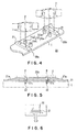
- FIG. 4 and 5 A structure for mounting bindings 20 is shown in Figs. 4 and 5 as another example of the present invention.
- the same numerals are used for the same members as those in the first embodiment.
- the structure for mounting bindings 20 comprises a front mounting section 20a and a rear mounting section 20b.
- Each of the front mounting section 20a and the rear mounting section 20b is made up of an outer fixing section (first mounting seat) 21 and an inner fixing section (second mounting seat) 15 provided at the inner side of the outer fixing section 21.
- Each outer fixing section 21 is molded of highly rigid material, the same as in the supporting bar 11a and the mounting bar 11b in Fig. 1. Although the overall length and width are about the same as those of the supporting bar 11a, the outer fixing section 21 is of a single member, which is different from Fig. 1. Therefore, the upper surface of the outer fixing section 21 becomes the mounting surface 21b for mounting the binding 2. As shown in Fig. 5, tapers 21a, 21a are formed in such a manner that the right and left edges of the outer fixing section 21 are inclined to the upward direction and continue to the mounting surface 21b.
- Two outer mounting holes 21c, 21c are formed at the mounting surface 21b so as to penetrate the outer fixing section 21.
- bolts 22, 22 into the lower half of the outer mounting holes 21c, 21c and holes formed in the snowboard 1 (not shown)
- the outer fixing section 21 is fixed to the snowboard 1.
- nuts are fixed in the upper half of the outer mounting holes 21c, and by screwing bolts B, B into these nuts, the binding 2 is fixed to the outer fixing section 21.
- the manufacturing process can be simplified to a certain extent and costs can be reduced.
- the outer fixing section 11 is made up of the supporting bar 11a and the mounting bar 11b, it is more likely to be responsive to the bendability of the board 1 by structuring the highly rigid outer fixing sections 11 made of two members rather than one member.
- the present invention is not limited to the first and the second embodiments.
- the insert nut of the soft mounting part can be a type of nut 30, on top of which a flange 31 is provided. Because the flange 31 is provided, the nut 30 will not easily come off.
- alpen type bindings are shown in Figs. 1 to 7, the present invention can also be applied to those for other types, such as free style. Suitable modifications are obviously also possible to the specific structural details etc.
- the outer sides of the bindings are mounted at the first mounting seats made of the rigid members, and the inner sides at the second mounting seats made of the soft members. Therefore, since the outer sides of the bindings are mounted on the snowboard via the first highly rigid mounting seats, shifting the direction of the weight of the rider is directly transmitted to the snowboard, and the snowboard is directly responsive to a turn in the horizontal direction. As a result, high responsive performance can be achieved.
- the shape of the second mounting seats freely varies according to the direction of the weight of the rider during riding, and flex of the snowboard is not interfered with. As a result, the tuning arc can be maintained as the rider intends.
- the snowboard by combining the first highly rigid mounting seats and the second highly flexible mounting seats, not only can the snowboard be fully bent and turned in the direction in which the rider intends to go, but it also exhibits quick response, and the riding performance can be improved.
Landscapes
- Clamps And Clips (AREA)
- Road Signs Or Road Markings (AREA)
Abstract
A structure (10) for mounting snowboard bindings (2) for turning a
snowboard (1) in the direction in which a rider intends to go without limiting flex,
and for increasing the riding performance of the snowboard, comprises outer fixing
sections (11) having highly rigid supporting bars (11a) and highly rigid mounting
bars (11b), and inner fixing sections (15) having highly flexible soft mounting parts
(15a). Since the outer fixing sections (11) are provided so as to cross the snowboard
(1) and almost reach the edges of the snowboard, shifting the direction of the weight
of the rider is directly transmitted to the edges, and as a result, high riding
performance can be achieved. In addition, because the shapes of the soft mounting
parts (15a) vary according to the direction of the weight of the rider during riding, the
snowboard can be fully bent and can be turned in the direction in which a rider
intends to go.
Description
- The present invention relates to a structure for mounting snowboard bindings.
- A snowboard is provided with bindings for fixing boots.
As shown in Fig. 7a, a type of related structure for mounting snowboard bindings where screw holes (not shown) are formed in asnowboard 1 andbindings - However, in the structure for mounting bindings in Fig. 7a, rigid body bindings made from aluminum alloys or hard resins are directly screwed into the
snowboard 1, causing the rigidity at these screwed portion to become higher than that of the other parts. As a result, flex (bendability in the lengthwise direction) of the snowboard during riding is limited, and flexibility of the snowboard itself can not be fully exhibited. Therefore, there are problems such as the shape of the turning arc that a rider generates becomes different from that the rider intended, or an edge of the snowboard contacting the snow surface partially works as a brake. - Therefore, as shown in Fig. 7b, a type of snowboard has been developed where mounting members 4, 4 made of relatively soft resin or rubber are fixed on the
snowboard 1, and thebindings - The aim of the present invention is, in a structure for mounting snowboard bindings, to make it possible to turn a snowboard in the direction in which a rider intends to go without limiting natural flex of the snowboard, and to improve the riding performance of the snowboard.
- In accordance with the present invention, a structure for mounting snowboarding bindings on a snowboard comprises:
- a pair of first mounting seats (outer fixing sections) made of hard members provided on the snowboard in a lengthwise direction being separated from each other by a prescribed distance; and a pair of second mounting seats (inner fixing sections) made of soft deformable members provided at inner sides of the first mounting seats.
-
- According to the structure of the present invention, the outer sides of the bindings are mounted on the first mounting seats made of hard members and inner sides of the bindings are mounted on the second mounting seats made of soft members. Therefore, since the outer sides of the bindings are mounted on the snowboard via the first highly rigid mounting seats, shifting the direction of the weight of a rider is directly transmitted to the snowboard, and the snowboard is directly responsive to a turn in the horizontal direction. As a result, highly responsive performance can be achieved.
- Since the inner sides of the bindings are mounted on the snowboard via the second soft mounting seats, the shape of the second mounting seats freely varies according to the direction of the weight of the rider during riding, and flex of the snowboard is not impeded. As a result, the turning arc can be maintained as the rider intends.
- In addition, because the first highly rigid mounting seats are provided at the outer side on the snowboard and the second highly flexible mounting seats are provided at the inner side on the snowboard, soles of both feet are naturally tilted toward the soft inner side or the center side of the rider when the rider applies pressures to both feet, and thus the center of gravity of the rider naturally becomes the center of the snowboard, allowing the rider to maintain a stable position.
- As described above, according to the structure of the present invention, by combining the first highly rigid mounting seats and the second highly flexible mounting seats, not only can the snowboard be fully bent and turned in the direction in which the rider intends to go, but it also shows quick a response and the riding performance can be improved.
- Each of the first mounting seats and the second mounting seats need not necessarily be formed from one member and may be formed from a plurality of members.
- Also, material and shape of each of the first mounting seats and the second mounting seats are not particularly limited as long as specified hardness, flexibility and strength is obtained. However, preferably the first mounting seats are mainly made of aluminum alloy, titanium alloy, or hard synthetic resin and formed into a bar shape or a plate shape, and that the second mounting seats are mainly made of rubber or polymeric elastomer and formed into a cylindrical shape or an elliptical shaft shape.
- By way of example only, specific embodiments of the present invention will now be described, with reference to the accompanying drawings, in which:-
- Fig. 1 is a perspective view showing a first embodiment of a structure for mounting snowboard bindings of the present invention, with front and rear ends of a snowboard omitted.
- Fig. 2 is a cross-sectional view showing an outer fixing section of the structure for mounting the bindings of Fig. 1.
- Fig. 3 is a cross-sectional view showing an inner fixing section of the structure for mounting the bindings of Fig. 1.
- Fig. 4 is a perspective view showing the second embodiment of the structure for mounting the snowboard bindings of the present invention, with front and rear ends of the snowboard omitted.
- Fig. 5 is a cross-sectional view showing the outer fixing member of the structure for mounting the bindings of Fig. 4.
- Fig. 6 is a cross-sectional view showing another example of an insert nut in a soft mounting part.
- Fig. 7 is a perspective view, both a and b of which show the related structure for mounting the snowboard bindings, with the front and rear ends of the snowboard omitted, of two prior art structures for mounting snowboard bindings.
-
- The following is a detailed description, with reference to Figs. 1 to 6, of embodiments of the present invention. In the drawings, bindings are shown by dotted lines, and the same numerals are used for the same members as those in Fig. 7.
- A structure for
mounting bindings 10 on a snowboard is shown in Fig. 1 as an example of the present invention. - The structure for
mounting bindings 10 comprises afront mounting section 10a for a front foot and arear mounting section 10b for a rear foot, being separated from each other by a prescribed distance. - Each of the
front mounting section 10a and therear mounting section 10b is made up of anouter fixing section 11 and aninner fixing section 15 provided at the inner side of theouter fixing section 11. - Fig. 2 shows a cross-sectional structure of each
outer fixing section 11. Theouter fixing section 11 is the first mounting seat of the present invention, and is made by combining amounting bar 11b on top of a supportingbar 11a, and is provided in the widthwise direction to cross asnowboard 1. The supportingbar 11a and themounting bar 11b are both obtained by forming highly rigid material such as aluminum alloy, titanium alloy, or hard synthetic resin into a rectangular bar of narrow width. The twoouter fixing sections outer fixing sections - The supporting
bar 11a has substantially the same length as the width of thesnowboard 1 and is fixed byscrews - Also the
mounting bar 11b is formed shorter than the supportingbar 11a and is fixed on the supportingbar 11a byscrews mounting bar 11b above thescrews outer nuts outer nuts mounting bar 11b. - The
inner fixing section 15 is the second mounting seat of the present invention and comprisessoft mounting parts soft mounting parts - A
mounting hole 15b is opened in the central section of eachsoft mounting part 15a, and aninsert nut 16 is embedded in themounting hole 15b. Thesoft mounting part 15a is formed into a cylindrical shape with a substantially elliptic surface in cross-section so as to surround themounting hole 15b. Theinsert nut 16 can he firmly fixed internally by being formed integrally with thesoft mounting part 15a or can be fixed by gluing in thesoft mounting part 15a after molding. - In addition, an embedded
bolt 17, on top of which aflange 17a is formed, is fixed below thesoft mounting part 15a. Theflange 17a is formed in an elliptic shape according to the shape of thesoft mounting part 15a and is formed integrally with thesoft mounting part 15a at the time of molding. By twisting the entiresoft mounting part 15a so that the embeddedbolt 17 is screwed into a bolt hole (not shown) formed in the snowboard, thesoft mounting parts 15a is fixed onto thesnowboard 1. - Incidentally, the shape of the cross-section of the
soft mounting parts 15a is not limited to an ellipse shape, and it can also be other shapes, e.g. a circle or a rectangle. Furthermore, theflange 17a may be altered according to the shape of thesoft mounting parts 15a. - For eacn of the
front mounting section 10a and therear mounting section 10b of the structure formounting bindings 10 in Figs. 1 to 3, thebinding 2 is mounted by fixing bolts of thebinding 2 into theouter nuts insert nuts - According to the above described embodiment, the structure for
mounting bindings 10 comprises theouter fixing sections 11 having the highly rigid supportingbars 11a and the highlyrigid mounting bars 11b, and theinner fixing sections 15 having the highly flexiblesoft mounting parts - Since the highly rigid
outer fixing sections 11 are provided so as to cross thesnowboard 1 and reach almost to the edges of thesnowboard 1, a shift in the direction of the weight of the rider is directly transmitted to the edges, the snowboard is directly responsive to a turn in the horizontal direction, and as a result, highly responsive performance can be achieved. - Meanwhile, although the
outer fixing sections 11 with high rigidity are provided, since both of the supportingbars 11a and the mountingbars 11b are narrow in width and cross thesnowboard 1 in the horizontal (widthwise) direction, without interfering with flex, that is bendability, of thesnowboard 1 in the lengthwise direction and without causing a braking phenomena due to uneven deformation, the rider can ride thesnowboard 1 while maintaining intended turning arcs. - Particularly, since the
outer fixing sections outer fixing sections 11 is relatively long, when the rider is changes the direction of thesnowboard 1 by twisting both feet, thesnowboard 1 is made to twist having theouter fixing sections snowboard 1 can be carried out easily. - Then, because the
inner fixing sections 15 provided inside of the each outer fixingsections 11 comprise thesoft mounting parts inner fixing sections 15 vary according to the direction of the weight of the rider and the snowboard is fully bent without interfering with flex during riding. - Also, since the
soft mounting parts holes - Furthermore, when the
outer fixing sections snowboard 1 and theinner fixing sections snowboard 1 and when the rider applies pressure to both feet, soles of both feet are naturally tilted toward the soft inner side or the center side of the rider, and thus the center of gravity of the rider naturally tends toward the center of thesnowboard 1, allowing the rider to maintain a stable position. - As described above, according to the structure for mounting
bindings 10, by combining the highly rigidouter fixing sections inner fixing sections 15, not only can thesnowboard 1 be turned in the direction in which the rider intends to go due to the flex of thesnowboard 1, but also highly responsive performance is achieved and riding performance can be improved. - A structure for mounting
bindings 20 is shown in Figs. 4 and 5 as another example of the present invention. The same numerals are used for the same members as those in the first embodiment. - The structure for mounting
bindings 20 comprises afront mounting section 20a and arear mounting section 20b. Each of thefront mounting section 20a and therear mounting section 20b is made up of an outer fixing section (first mounting seat) 21 and an inner fixing section (second mounting seat) 15 provided at the inner side of theouter fixing section 21. - Each
outer fixing section 21 is molded of highly rigid material, the same as in the supportingbar 11a and the mountingbar 11b in Fig. 1. Although the overall length and width are about the same as those of the supportingbar 11a, theouter fixing section 21 is of a single member, which is different from Fig. 1. Therefore, the upper surface of theouter fixing section 21 becomes the mountingsurface 21b for mounting the binding 2. As shown in Fig. 5, tapers 21a, 21a are formed in such a manner that the right and left edges of theouter fixing section 21 are inclined to the upward direction and continue to the mountingsurface 21b. - Two outer mounting
holes surface 21b so as to penetrate theouter fixing section 21. By fittingbolts holes outer fixing section 21 is fixed to the snowboard 1.In addition, nuts (not shown) are fixed in the upper half of the outer mountingholes 21c, and by screwing bolts B, B into these nuts, the binding 2 is fixed to theouter fixing section 21. - According to the above structure for mounting
bindings 20, the same results can be obtained as in the structure for mountingbindings 10. - Incidentally, when comparing the structure for mounting
bindings 10 with 20, in the structure for mountingbindings 20, since theouter fixing section 21 is of one member, the manufacturing process can be simplified to a certain extent and costs can be reduced. On the other hand, in the structure for mountingbindings 10, since theouter fixing section 11 is made up of the supportingbar 11a and the mountingbar 11b, it is more likely to be responsive to the bendability of theboard 1 by structuring the highly rigidouter fixing sections 11 made of two members rather than one member. - Incidentally, the present invention is not limited to the first and the second embodiments.
- For example, the insert nut of the soft mounting part, as shown in Fig. 6, can be a type of
nut 30, on top of which aflange 31 is provided. Because theflange 31 is provided, thenut 30 will not easily come off. - Further, although alpen type bindings are shown in Figs. 1 to 7, the present invention can also be applied to those for other types, such as free style. Suitable modifications are obviously also possible to the specific structural details etc.
- According to the structure for mounting the bindings of the present invention, the outer sides of the bindings are mounted at the first mounting seats made of the rigid members, and the inner sides at the second mounting seats made of the soft members. Therefore, since the outer sides of the bindings are mounted on the snowboard via the first highly rigid mounting seats, shifting the direction of the weight of the rider is directly transmitted to the snowboard, and the snowboard is directly responsive to a turn in the horizontal direction. As a result, high responsive performance can be achieved.
- Since the inner side of the bindings are mounted on the snowboard via the second soft mounting seats, the shape of the second mounting seats freely varies according to the direction of the weight of the rider during riding, and flex of the snowboard is not interfered with. As a result, the tuning arc can be maintained as the rider intends.
- As described above, by combining the first highly rigid mounting seats and the second highly flexible mounting seats, not only can the snowboard be fully bent and turned in the direction in which the rider intends to go, but it also exhibits quick response, and the riding performance can be improved.
Claims (2)
- A structure for mounting snowboarding bindings on a snowboard, comprising:a pair of first mounting seats made of hard material provided on the snowboard in a lengthwise direction being separated from each other by a prescribed distance, anda pair of second mounting seats made of soft deformable material provided at inner sides of the first mounting seats.
- A structure for mounting snowboarding bindings according to claim 1, wherein:the first mounting seats are mainly made of aluminum alloy, titanium alloy, or hard synthetic resin and formed into a bar shape or a plate shape, and:the second mounting seats are mainly made of rubber or polymeric elastomer and formed into a cylindrical shape or an elliptical shaft shape.
Applications Claiming Priority (2)
| Application Number | Priority Date | Filing Date | Title |
|---|---|---|---|
| JP2001047105 | 2001-02-22 | ||
| JP2001047105A JP2002239058A (en) | 2001-02-22 | 2001-02-22 | Snowboard binding mounting structure |
Publications (1)
| Publication Number | Publication Date |
|---|---|
| EP1234605A1 true EP1234605A1 (en) | 2002-08-28 |
Family
ID=18908607
Family Applications (1)
| Application Number | Title | Priority Date | Filing Date |
|---|---|---|---|
| EP02251148A Withdrawn EP1234605A1 (en) | 2001-02-22 | 2002-02-20 | Structure for mounting snowboard bindings |
Country Status (4)
| Country | Link |
|---|---|
| US (1) | US20020113384A1 (en) |
| EP (1) | EP1234605A1 (en) |
| JP (1) | JP2002239058A (en) |
| CA (1) | CA2372520A1 (en) |
Families Citing this family (1)
| Publication number | Priority date | Publication date | Assignee | Title |
|---|---|---|---|---|
| US9364738B2 (en) * | 2013-10-21 | 2016-06-14 | Henry Kim | Recreational board riser |
Citations (3)
| Publication number | Priority date | Publication date | Assignee | Title |
|---|---|---|---|---|
| DE2723864A1 (en) * | 1977-05-26 | 1978-11-30 | Kittmann | Monoski with two ski bindings - has bindings positioned on pedestals inclined in opposite directions, one behind other |
| EP0612546A2 (en) * | 1993-02-23 | 1994-08-31 | Techno Circle | Snowboard binding |
| US5580077A (en) * | 1994-06-08 | 1996-12-03 | The Burton Corporation | Rider supporting assembly for snowboards |
-
2001
- 2001-02-22 JP JP2001047105A patent/JP2002239058A/en active Pending
-
2002
- 2002-02-18 CA CA002372520A patent/CA2372520A1/en not_active Abandoned
- 2002-02-20 EP EP02251148A patent/EP1234605A1/en not_active Withdrawn
- 2002-02-21 US US10/078,358 patent/US20020113384A1/en not_active Abandoned
Patent Citations (3)
| Publication number | Priority date | Publication date | Assignee | Title |
|---|---|---|---|---|
| DE2723864A1 (en) * | 1977-05-26 | 1978-11-30 | Kittmann | Monoski with two ski bindings - has bindings positioned on pedestals inclined in opposite directions, one behind other |
| EP0612546A2 (en) * | 1993-02-23 | 1994-08-31 | Techno Circle | Snowboard binding |
| US5580077A (en) * | 1994-06-08 | 1996-12-03 | The Burton Corporation | Rider supporting assembly for snowboards |
Also Published As
| Publication number | Publication date |
|---|---|
| US20020113384A1 (en) | 2002-08-22 |
| CA2372520A1 (en) | 2002-08-22 |
| JP2002239058A (en) | 2002-08-27 |
Similar Documents
| Publication | Publication Date | Title |
|---|---|---|
| US5819440A (en) | Back support for a snowboard boot | |
| JP3947658B2 (en) | Midsole structure for sports shoes | |
| US7533480B2 (en) | Bicycle shoe sole having coupling member | |
| US6729047B2 (en) | Strap assembly for sport shoe | |
| US6315305B1 (en) | Snowboard binding having adjustable toe | |
| US7073813B2 (en) | Athletic boot with interface adjustment mechanism | |
| JPS63229001A (en) | Sole for sports shoes | |
| US5957470A (en) | Flexible skate | |
| US6301771B1 (en) | Method of manufacturing a chassis for a gliding sport | |
| JP2022530932A (en) | Shoes designed to enhance physical activity practices | |
| JP2002531191A (en) | Spacer | |
| EP0785126B1 (en) | Clipless bicycle pedal with large shoe contacting area | |
| JP2002037173A (en) | Automatic pedal of bicycle | |
| US11724770B2 (en) | Cycling cleat and a cycling pedal | |
| CN1726064A (en) | Snowboard binding with suspension heel loop | |
| JP2008520379A (en) | Ski with suspension | |
| WO2009128586A1 (en) | Skateboard having good property in torsion and bending | |
| US7537220B2 (en) | Skateboard system | |
| US20020113384A1 (en) | Structure for mounting snowboard bindings | |
| US7703794B2 (en) | Canting device for a snowboard binding and methods | |
| US6234513B1 (en) | Snowboard drive system | |
| US6145854A (en) | In-line roller skate | |
| WO2011086639A1 (en) | Snowboard binding | |
| EP0892660A1 (en) | Frame for skates, in particular skates with longitudinally aligned wheels, and method for forming the frame | |
| CN105899264B (en) | Snow face skiing tool |
Legal Events
| Date | Code | Title | Description |
|---|---|---|---|
| PUAI | Public reference made under article 153(3) epc to a published international application that has entered the european phase |
Free format text: ORIGINAL CODE: 0009012 |
|
| AK | Designated contracting states |
Kind code of ref document: A1 Designated state(s): AT BE CH CY DE DK ES FI FR GB GR IE IT LI LU MC NL PT SE TR |
|
| AX | Request for extension of the european patent |
Free format text: AL;LT;LV;MK;RO;SI |
|
| AKX | Designation fees paid | ||
| REG | Reference to a national code |
Ref country code: DE Ref legal event code: 8566 |
|
| STAA | Information on the status of an ep patent application or granted ep patent |
Free format text: STATUS: THE APPLICATION IS DEEMED TO BE WITHDRAWN |
|
| 18D | Application deemed to be withdrawn |
Effective date: 20030301 |