EP1234103B1 - Arrangement for feeding bonding material - Google Patents
Arrangement for feeding bonding material Download PDFInfo
- Publication number
- EP1234103B1 EP1234103B1 EP00985299A EP00985299A EP1234103B1 EP 1234103 B1 EP1234103 B1 EP 1234103B1 EP 00985299 A EP00985299 A EP 00985299A EP 00985299 A EP00985299 A EP 00985299A EP 1234103 B1 EP1234103 B1 EP 1234103B1
- Authority
- EP
- European Patent Office
- Prior art keywords
- nozzle
- bolt
- feed chamber
- soldering material
- feeding
- Prior art date
- Legal status (The legal status is an assumption and is not a legal conclusion. Google has not performed a legal analysis and makes no representation as to the accuracy of the status listed.)
- Expired - Lifetime
Links
- 239000000463 material Substances 0.000 title claims abstract description 43
- 238000005476 soldering Methods 0.000 claims abstract description 43
- 239000011435 rock Substances 0.000 claims abstract description 19
- 238000007789 sealing Methods 0.000 claims description 7
- 238000005553 drilling Methods 0.000 description 5
- 238000010276 construction Methods 0.000 description 1
- 230000007797 corrosion Effects 0.000 description 1
- 238000005260 corrosion Methods 0.000 description 1
- 239000012530 fluid Substances 0.000 description 1
- 238000005065 mining Methods 0.000 description 1
Images


Classifications
-
- E—FIXED CONSTRUCTIONS
- E21—EARTH DRILLING; MINING
- E21D—SHAFTS; TUNNELS; GALLERIES; LARGE UNDERGROUND CHAMBERS
- E21D21/00—Anchoring-bolts for roof, floor in galleries or longwall working, or shaft-lining protection
- E21D21/0026—Anchoring-bolts for roof, floor in galleries or longwall working, or shaft-lining protection characterised by constructional features of the bolts
-
- E—FIXED CONSTRUCTIONS
- E21—EARTH DRILLING; MINING
- E21D—SHAFTS; TUNNELS; GALLERIES; LARGE UNDERGROUND CHAMBERS
- E21D20/00—Setting anchoring-bolts
- E21D20/02—Setting anchoring-bolts with provisions for grouting
- E21D20/028—Devices or accesories for injecting a grouting liquid in a bore-hole
Definitions
- the invention relates to an arrangement for feeding soldering material into a space between a bolt and rock using a rockbolt for bolting, which comprises a separate guide tube around the actual bolt, the guide tube being connected to a feed chamber, which is provided with a feed hole for feeding soldering material into the feed chamber and further into a drill hole through the guide tube, the bolt being arranged to travel through the feed chamber so that it can be fixed in the hole before feeding the soldering material.
- soldering material can be fed into the feed chamber through this hole and a nozzle for soldering material pushed into the hole and further inside the above-mentioned tube through the feed chamber. From the tube, the soldering material flows along an annular channel between the tube and the bolt to the end of the bolt and back to the beginning of the tube along an annular channel between the tube and the hole walls.
- the free space can be filled with soldering material reliably and efficiently, and it can be noted that the space is filled up as concrete starts to penetrate out of the hole.
- the flange is provided with a hole through which the soldering material that has got between the flange and the rock can penetrate, and thus it can be noted that the hole is filled up.
- An object of the present invention is to provide an arrangement which enables filling of a drill hole with soldering material safely, easily and, thanks to mechanization, economically using a rockbolt provided with a guide tube and a feed chamber.
- the arrangement according to the invention is characterized in that it comprises a sleeve-like nozzle which can be placed tightly around the feed chamber so that the feed hole of the feed chamber is connected to the inner space of the nozzle, and that the arrangement comprises means for feeding soldering material inside the nozzle and therethrough into the feed chamber, and means for placing the nozzle around the feed chamber.
- the invention is based on the idea of using, instead of a nozzle for soldering material which is difficult to push tightly into a hole provided on the side of the feed chamber, a sleeve-like nozzle which in the operating position surrounds the feed chamber and in which the inner circumference of the sleeve tightens against the outer surface of the feed chamber and/or the front edge of the sleeve tightens against the flange so that soldering material, when fed into the sleeve, cannot penetrate from between the sleeve and the flange or from between the sleeve and the outer surface of the feed chamber.
- the material penetrates into the guide tube through the hole on the side of the feed chamber and further inside the upper part of the bolt, and back down from between the guide tube and the drill hole, which was the intention in the design of the bolt.
- Another basic idea is that the sleeve-like nozzle is connected to mechanical means which can place it on top of the feed chamber so that soldering material can be fed safely by feeding means of soldering material attached to the nozzle, the feeding means being guided by actuators provided in the usual place on the base of the drilling device. Thus the user does not need to move from his position to feed soldering material.
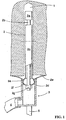
- FIG. 1 schematically illustrates a bolt 2 pushed into a drill hole 1, the upper end of the bolt being provided with locking members 2a.
- the locking members 2a may be implemented using any suitable means of locking, such as wedge locking.
- the lower end of the tube is connected to a feed chamber 2d.
- the feed chamber 2d is round in cross-section and comprises a feed hole 2f through which soldering material can be fed into the feed chamber 2d and further inside the guide tube 2c.
- the actual bolt part 2b travels through the feed chamber 2d and a nut 2g or another clamping member for tightening the bolt using wedge locking to provide adequate tightness before feeding soldering material.
- the figure also shows a sleeve-like nozzle 3 for soldering material which is placed around the feed chamber 2d after the bolt 2 has been tightened.
- the nozzle 3 comprises a sealing surface 3a which settles tightly along the outer surface of the feed chamber 2d, thus forming a tight joint with the feed chamber 2d.
- the sealing surface may be formed on the sleeve-like inner surface of the nozzle to provide a slightly conical sleeve-like inner surface as shown in the figure. In that case, as the nozzle is pushed, the conical sealing surface 3a is pressed against the outer surface of the feed chamber 2d, which is round in cross-section, thus forming a line-like contacting surface which functions as a seal.
- soldering material can be fed into the nozzle through the hose and from the nozzle into the feed chamber and further.
- the nozzle 3 is connected to a supporting arm 5 shown in the figure or to another supporting member by means of which it can be pushed into its place for feeding of the soldering material.
- a device suitable for this purpose is shown in greater detail in Figures 4a and 4b.
- Figures 2a to 2c illustrate embodiments for tightening the nozzle 3 against the feed chamber 2d or the flange 2e, which differ from those shown in Figure 1.
- Figure 2a illustrates an embodiment where a seal 3b for sealing the nozzle 3 against the feed chamber 2d is provided on the inner surface of the nozzle 3.
- the inner surface of the seal 3b is preferably slightly conical, in which case it will seal easily against the feed chamber 2d.
- the inner surface of the seal may also have a different shape, i.e. the inner surface can be completely cylindrical or partly cylindrical with a conical front edge. Seals of other kind can also be used.
- Figure 2b illustrates a solution in which a seal 3c is provided at the front edge of the nozzle 3, the seal being pressed against the flange 2e as the nozzle 3 is placed in its operating position around the feed chamber 2d.
- Figure 2c shows a solution in which the nozzle 3 is provided with a sleeve-like seal 3d, which forms a uniform seal from inside the nozzle 3 to its front edge, preferably beyond the front surface as shown in the figure.
- a sleeve-like seal is easy to produce and install, and it can be changed quickly when it is worn out.
- FIGs 3a and 3b are schematic side and top views of a rock bolting apparatus in which the arrangement can be applied.
- the rock bolting device 6 is pivoted to the boom 7 in a manner known per se, for which reason this is not described in greater detail.
- the rock bolting device 6 comprises e.g. a drilling machine for drilling a hole in the rock first.
- the drilling machine moves along a feed beam 8 as shown in the figure.
- the apparatus may also include a bolt cartridge and transfer members known per se (not shown) for transferring bolts to the feeding device 11.
- a bolt cartridge and transfer members known per se (not shown) for transferring bolts to the feeding device 11.
- Such bolt cartridges and transfer members are fully known per se, and since they are not relevant to the present invention, they will not be described in greater detail.
- the rock bolting device further comprises a vertical joint 12, which is parallel with the axis of the feed beams 8 and 10 and around which the rock bolting device can be turned so that the rock drilling machine 9 and the bolt feeding device 11 will be in the same place to allow remote-controlled, or if desired, totally automatic feeding of a bolt into a drilled hole.
- indexing which is fully known per se e.g. from German patent no. 2222646, and thus its function and actuators need not be described in greater detail.
- the figure shows a feeding unit 13 for soldering material, which is provided with a sleeve-like nozzle of Figures 1 or 2a to 2c included in the arrangement according to the invention.
- This sleeve-like nozzle is arranged with respect to the axis 12 so that it can be turned coaxially with the drilled hole.
- the nozzle 3 can preferably be moved with respect to the bolting device 6 parallel with the axis 12, and it comprises an actuator 14, preferably a pressure-fluid operated cylinder, by means of which the nozzle 3 can be firmly placed around the feed chamber of the bolt and held there to feed preferably concrete into the drill hole around the bolt through the feed chamber.
- FIGs 4a and 4b schematically illustrate other embodiments of the nozzles included in the arrangement according to the invention.
- the nozzle 3' is also sleeve-like and is arranged in the bolt feeding device 11.
- the bolt feeding device 11, which moves along the feed beam 10 shown in Figures 3a and 3b when a bolt is being fed, comprises a rotating tool 11a, which contains a clamping space 11 b for a clamping member, such as the nut 2g of the bolt or the like, which rotates the nut 2g of the bolt shown in the figure during pre-fastening of the bolt.
- the tool 11a is arranged to pass through the bottom of the nozzle 3' and sealed against the nozzle with a seal 11 c so that soldering material cannot penetrate out from between the nozzle 3' and the tool 11 a.
- the bolt can be pushed into its place when the nozzle 3' is around the feed chamber 2d of the bolt. After the bolt has been pushed into the hole, it can be pre-tightened to its place by the tool 11a, after which soldering material can be immediately fed into the drill hole through the feed chamber 2d. It is also possible to start feeding of soldering material already during tightening of the nut.
- Figure 4b illustrates another embodiment of the arrangement of the invention where the tool 11 a of the bolt feeding device 11 is provided with one or more openings 11d, such as holes, which, extend from the clamping space 11b of the tool 11 a to the outer surface of the tool 11a.
- the tool 11 a can be implemented in several ways, provided that it can rotate the nut of the bolt and any other component of any shape used for tightening. It is essential that the tool and the component used for tightening are compatible so that the bolt can be pre-tightened to its place.
- a bolt the upper end of which is provided with threads or a similar component which is rotated to provide pre-tightening can also be applied in the arrangement of the invention.
- the arrangement comprise a sleeve-like nozzle which can be arranged around the feed chamber of the bolt so that it seals against the feed chamber and/or the flange, which enables feeding of soldering material into the drill hole through the feed chamber in the intended manner.
- soldering can be performed even though the bolt were not provided with a tube around it in accordance with US patent no. 5,636,945, but with a feed chamber in connection with the flange.
Abstract
Description
- The invention relates to an arrangement for feeding soldering material into a space between a bolt and rock using a rockbolt for bolting, which comprises a separate guide tube around the actual bolt, the guide tube being connected to a feed chamber, which is provided with a feed hole for feeding soldering material into the feed chamber and further into a drill hole through the guide tube, the bolt being arranged to travel through the feed chamber so that it can be fixed in the hole before feeding the soldering material.
- To support rock in tunnel construction and mining, it is nowadays rather common to use a rockbult in which the end to be pushed into the hole is provided with locking members, such as a wedge anchor, which is then tightened with a support flange and a nut included in the bolt. To fix the bolt firmly to the rock and to protect it from corrosion, the space between the bolt and the hole wall has to be filled with soldering material, such as concrete. In practice, it has been difficult to implement soldering, which has led to development of a new bolt structure, which is described in US patent no. 5,636,945. In this solution, a tube to be arranged around the bolt is fastened to a support flange, which will rest against the rock surface, and connected to the feed chamber attached to the flange. There is a hole on the side of the feed chamber, and soldering material can be fed into the feed chamber through this hole and a nozzle for soldering material pushed into the hole and further inside the above-mentioned tube through the feed chamber. From the tube, the soldering material flows along an annular channel between the tube and the bolt to the end of the bolt and back to the beginning of the tube along an annular channel between the tube and the hole walls. Thus the free space can be filled with soldering material reliably and efficiently, and it can be noted that the space is filled up as concrete starts to penetrate out of the hole. According to the above-mentioned patent, the flange is provided with a hole through which the soldering material that has got between the flange and the rock can penetrate, and thus it can be noted that the hole is filled up.
- In this bolt structure it is, however, difficult to fill the space with soldering material. To feed soldering material into the feed chamber reliably, the nozzle for soldering material has to be pushed manually into a hole on the side of the feed chamber. This is laborious, difficult and slows down the bolting considerably. Furthermore, in most cases the worker has to be in a cage or the like to reach to bolt, even though the bolt could be fed and the nut tightened mechanically with a bolting device. The above-mentioned manual stages also pose a considerable safety risk because the worker has to work under a rock that has not been reinforced.
- An object of the present invention is to provide an arrangement which enables filling of a drill hole with soldering material safely, easily and, thanks to mechanization, economically using a rockbolt provided with a guide tube and a feed chamber. The arrangement according to the invention is characterized in that it comprises a sleeve-like nozzle which can be placed tightly around the feed chamber so that the feed hole of the feed chamber is connected to the inner space of the nozzle, and that the arrangement comprises means for feeding soldering material inside the nozzle and therethrough into the feed chamber, and means for placing the nozzle around the feed chamber.
- The invention is based on the idea of using, instead of a nozzle for soldering material which is difficult to push tightly into a hole provided on the side of the feed chamber, a sleeve-like nozzle which in the operating position surrounds the feed chamber and in which the inner circumference of the sleeve tightens against the outer surface of the feed chamber and/or the front edge of the sleeve tightens against the flange so that soldering material, when fed into the sleeve, cannot penetrate from between the sleeve and the flange or from between the sleeve and the outer surface of the feed chamber. Instead, the material penetrates into the guide tube through the hole on the side of the feed chamber and further inside the upper part of the bolt, and back down from between the guide tube and the drill hole, which was the intention in the design of the bolt. Another basic idea is that the sleeve-like nozzle is connected to mechanical means which can place it on top of the feed chamber so that soldering material can be fed safely by feeding means of soldering material attached to the nozzle, the feeding means being guided by actuators provided in the usual place on the base of the drilling device. Thus the user does not need to move from his position to feed soldering material.
- The invention will be described in greater detail in the accompanying drawings, in which
- Figure 1 schematically illustrates a bolt provided in a drill hole and feeding of soldering material with a nozzle member belonging to the arrangement according to the invention,
- Figures 2a to 2c illustrate tightening of the nozzle member to the feed chamber of the bolt and to the flange in greater detail,
- Figures 3a and 3b schematically illustrate a bolting device by means of which soldering material can be fed using the arrangement of the invention, and
- Figures 4a and 4b schematically illustrate another embodiment of the arrangement according to the invention.
- Figure 1 schematically illustrates a
bolt 2 pushed into a drill hole 1, the upper end of the bolt being provided withlocking members 2a. Thelocking members 2a may be implemented using any suitable means of locking, such as wedge locking. There is aguide tube 2c around thepart 2b of the bolt that actually carries the load. The lower end of the tube is connected to afeed chamber 2d. There is also aflange 2e attached to the feed chamber so that theguide tube 2c,feed chamber 2d andflange 2e form an entity. Thefeed chamber 2d is round in cross-section and comprises afeed hole 2f through which soldering material can be fed into thefeed chamber 2d and further inside theguide tube 2c. Theactual bolt part 2b travels through thefeed chamber 2d and anut 2g or another clamping member for tightening the bolt using wedge locking to provide adequate tightness before feeding soldering material. - The figure also shows a sleeve-
like nozzle 3 for soldering material which is placed around thefeed chamber 2d after thebolt 2 has been tightened. Thenozzle 3 comprises asealing surface 3a which settles tightly along the outer surface of thefeed chamber 2d, thus forming a tight joint with thefeed chamber 2d. The sealing surface may be formed on the sleeve-like inner surface of the nozzle to provide a slightly conical sleeve-like inner surface as shown in the figure. In that case, as the nozzle is pushed, theconical sealing surface 3a is pressed against the outer surface of thefeed chamber 2d, which is round in cross-section, thus forming a line-like contacting surface which functions as a seal. There is also adelivery hose 4 connected to thenozzle 3. Soldering material can be fed into the nozzle through the hose and from the nozzle into the feed chamber and further. Thenozzle 3 is connected to a supportingarm 5 shown in the figure or to another supporting member by means of which it can be pushed into its place for feeding of the soldering material. A device suitable for this purpose is shown in greater detail in Figures 4a and 4b. - Figures 2a to 2c illustrate embodiments for tightening the
nozzle 3 against thefeed chamber 2d or theflange 2e, which differ from those shown in Figure 1. Figure 2a illustrates an embodiment where aseal 3b for sealing thenozzle 3 against thefeed chamber 2d is provided on the inner surface of thenozzle 3. The inner surface of theseal 3b is preferably slightly conical, in which case it will seal easily against thefeed chamber 2d. The inner surface of the seal may also have a different shape, i.e. the inner surface can be completely cylindrical or partly cylindrical with a conical front edge. Seals of other kind can also be used. Figure 2b illustrates a solution in which aseal 3c is provided at the front edge of thenozzle 3, the seal being pressed against theflange 2e as thenozzle 3 is placed in its operating position around thefeed chamber 2d. Figure 2c shows a solution in which thenozzle 3 is provided with a sleeve-like seal 3d, which forms a uniform seal from inside thenozzle 3 to its front edge, preferably beyond the front surface as shown in the figure. Such a sleeve-like seal is easy to produce and install, and it can be changed quickly when it is worn out. - Figures 3a and 3b are schematic side and top views of a rock bolting apparatus in which the arrangement can be applied. A
rock bolting device 6, which is fully known per se and described e.g. in German patent no. 2222646, is attached to aboom 7 whose one end is attached to a base (not shown), which is fully known per se. Therock bolting device 6 is pivoted to theboom 7 in a manner known per se, for which reason this is not described in greater detail. Therock bolting device 6 comprises e.g. a drilling machine for drilling a hole in the rock first. The drilling machine moves along afeed beam 8 as shown in the figure. It further comprises abolt feeding device 11, which moves along anotherfeed beam 10. The apparatus may also include a bolt cartridge and transfer members known per se (not shown) for transferring bolts to thefeeding device 11. Such bolt cartridges and transfer members are fully known per se, and since they are not relevant to the present invention, they will not be described in greater detail. The rock bolting device further comprises avertical joint 12, which is parallel with the axis of thefeed beams rock drilling machine 9 and thebolt feeding device 11 will be in the same place to allow remote-controlled, or if desired, totally automatic feeding of a bolt into a drilled hole. This is called indexing, which is fully known per se e.g. from German patent no. 2222646, and thus its function and actuators need not be described in greater detail. - In addition, the figure shows a
feeding unit 13 for soldering material, which is provided with a sleeve-like nozzle of Figures 1 or 2a to 2c included in the arrangement according to the invention. This sleeve-like nozzle is arranged with respect to theaxis 12 so that it can be turned coaxially with the drilled hole. Thenozzle 3 can preferably be moved with respect to thebolting device 6 parallel with theaxis 12, and it comprises anactuator 14, preferably a pressure-fluid operated cylinder, by means of which thenozzle 3 can be firmly placed around the feed chamber of the bolt and held there to feed preferably concrete into the drill hole around the bolt through the feed chamber. - Figures 4a and 4b schematically illustrate other embodiments of the nozzles included in the arrangement according to the invention. In these embodiments the
nozzle 3' is also sleeve-like and is arranged in thebolt feeding device 11. Thebolt feeding device 11, which moves along thefeed beam 10 shown in Figures 3a and 3b when a bolt is being fed, comprises arotating tool 11a, which contains a clampingspace 11 b for a clamping member, such as thenut 2g of the bolt or the like, which rotates thenut 2g of the bolt shown in the figure during pre-fastening of the bolt. In this embodiment thetool 11a is arranged to pass through the bottom of thenozzle 3' and sealed against the nozzle with aseal 11 c so that soldering material cannot penetrate out from between thenozzle 3' and thetool 11 a. In. this embodiment the bolt can be pushed into its place when thenozzle 3' is around thefeed chamber 2d of the bolt. After the bolt has been pushed into the hole, it can be pre-tightened to its place by thetool 11a, after which soldering material can be immediately fed into the drill hole through thefeed chamber 2d. It is also possible to start feeding of soldering material already during tightening of the nut. Figure 4b illustrates another embodiment of the arrangement of the invention where thetool 11 a of thebolt feeding device 11 is provided with one ormore openings 11d, such as holes, which, extend from the clampingspace 11b of thetool 11 a to the outer surface of thetool 11a. In that case any soldering material that has penetrated into the clampingspace 11b can exit it when the next bolt is introduced, and thus the clampingspace 11 b cannot fill with soldering material, which might interrupt the bolting. Naturally, thetool 11 a can be implemented in several ways, provided that it can rotate the nut of the bolt and any other component of any shape used for tightening. It is essential that the tool and the component used for tightening are compatible so that the bolt can be pre-tightened to its place. A bolt the upper end of which is provided with threads or a similar component which is rotated to provide pre-tightening can also be applied in the arrangement of the invention. - The above description and drawings only exemplify the invention and do not limit the invention in any way. It is essential that the arrangement comprise a sleeve-like nozzle which can be arranged around the feed chamber of the bolt so that it seals against the feed chamber and/or the flange, which enables feeding of soldering material into the drill hole through the feed chamber in the intended manner. Thus soldering can be performed even though the bolt were not provided with a tube around it in accordance with US patent no. 5,636,945, but with a feed chamber in connection with the flange.
Claims (8)
- An arrangement for feeding soldering material into a space between a bolt and rock using a rockbolt for bolting, which comprises a separate guide tube (2c) around the actual bolt (2), the tube being connected to a feed chamber (2d), which is provided with a feed hole (2f) for feeding soldering material into the feed chamber and further into the drill hole through the guide tube, the bolt being arranged to travel through the feed chamber so that it can be fixed in the hole before feeding the soldering material, characterized in that the arrangement comprises a sleeve-like nozzle (3), which can be placed tightly around the feed chamber (2d) so that the feed hole (2f) of the feed chamber (2d) is connected to the inner space of the nozzle (3), and that the arrangement comprises means for feeding soldering material inside the nozzle (3) and therethrough into the feed chamber (2d), and means for placing the nozzle (3) around the feed chamber (2d).
- An arrangement according to claim 1, characterized in that the inner surface of the nozzle (3) is provided with a sealing surface (3a), which is arranged to be pressed against the outer surface of the feed chamber (2d).
- An arrangement according to claim 2, characterized in that the sealing surface (3a) of the nozzle (3) consists of a separate seal (3b) inside the nozzle (3).
- An arrangement according to any one of claims 1 to 3, characterized in that the front edge of the nozzle (3) is provided with a seal (3c), which is arranged to be pressed in a bolt provided with a flange (2e) against the surface of the flange (2e).
- An arrangement according to any one of claims 1 to 4, characterized in that the sleeve (3) comprises a separate sleeve-like seal (3d), which extends from its inner surface up to its front edge, thus forming a sealing surface both on the inner surface of the sleeve and at its front edge.
- An arrangement according to any one of the preceding claims, characterized in that the nozzle (3) is arranged in a bolt feeding device (11) in a rock bolting device (6) known per se, that the bolt feeding device comprises a clamping tool (11a) which is arranged to rotate the clamping member of the bolt (2), such as a nut (2g) or the like, and that the clamping tool (11a) is arranged to travel through the nozzle (3) in its axial direction so that the bolt (2) can be pushed into a drill hole with the bolt feeding device and tightened to its place and soldering material can be fed into the feed chamber (2g) through the nozzle (3) and further into the drill hole substantially in one stage.
- An arrangement according to claim 6, characterized in that the tool (11 a) of the bolt feeding device (11) comprises a clamping space in which the clamping member of the bolt (2) can settle, and that there is at least one opening (11d) from the clamping space (11b) to the side of the tool (11a) so that soldering material that has penetrated into the clamping space can exit it as the clamping member of a new bolt is introduced into the clamping space.
- An arrangement according to any one of claims 1 to 6, characterized in that the nozzle (3) is arranged in a rock bolting device known per se and that it comprises at least one actuator for transferring the bolt in the longitudinal direction of the nozzle around the feed chamber (2d) and for removing it from around the chamber.
Applications Claiming Priority (3)
| Application Number | Priority Date | Filing Date | Title |
|---|---|---|---|
| FI992597A FI110540B (en) | 1999-12-02 | 1999-12-02 | Arrangement for input of solder |
| FI992597 | 1999-12-02 | ||
| PCT/FI2000/001063 WO2001040628A1 (en) | 1999-12-02 | 2000-12-01 | Arrangement for feeding bonding material |
Publications (2)
| Publication Number | Publication Date |
|---|---|
| EP1234103A1 EP1234103A1 (en) | 2002-08-28 |
| EP1234103B1 true EP1234103B1 (en) | 2006-03-08 |
Family
ID=8555689
Family Applications (1)
| Application Number | Title | Priority Date | Filing Date |
|---|---|---|---|
| EP00985299A Expired - Lifetime EP1234103B1 (en) | 1999-12-02 | 2000-12-01 | Arrangement for feeding bonding material |
Country Status (11)
| Country | Link |
|---|---|
| US (1) | US6802674B2 (en) |
| EP (1) | EP1234103B1 (en) |
| JP (1) | JP4414626B2 (en) |
| AT (1) | ATE319916T1 (en) |
| AU (1) | AU776354B2 (en) |
| CA (1) | CA2392557C (en) |
| DE (1) | DE60026595D1 (en) |
| FI (1) | FI110540B (en) |
| NO (1) | NO317698B1 (en) |
| WO (1) | WO2001040628A1 (en) |
| ZA (1) | ZA200203561B (en) |
Families Citing this family (6)
| Publication number | Priority date | Publication date | Assignee | Title |
|---|---|---|---|---|
| CA2494781C (en) * | 2002-08-02 | 2010-10-26 | Dywidag-Systems International Pty Limited | Rock bolt post grouting apparatus |
| DE102006000042A1 (en) * | 2006-01-31 | 2007-08-02 | Hilti Ag | Adapter part of a self-drilling rock anchor |
| CL2011000042A1 (en) | 2011-01-07 | 2011-06-17 | Fortification system comprising a standard helical bar, an expansion head adapted to the thread of the bar, an element of plastic material, a corrugated plastic tube, a standard fortification plate and a threaded fortification nut according to the helical bolt that use. | |
| FI124908B (en) * | 2011-02-24 | 2015-03-13 | Suomen Metallityö Oy | rock bolt |
| WO2020047562A1 (en) * | 2018-08-28 | 2020-03-05 | Epiroc Holdings South Africa (Pty) Ltd | An integrated bolt rotator and grout nozzle device for use in a mechanised bolting application |
| US11674390B2 (en) * | 2019-11-22 | 2023-06-13 | Innovative Mining Products (Pty) Ltd | Resin-grouted rock bolt assembly with an adapted sealing bush |
Family Cites Families (19)
| Publication number | Priority date | Publication date | Assignee | Title |
|---|---|---|---|---|
| US636945A (en) * | 1898-10-26 | 1899-11-14 | John A Bergman | Washing-machine. |
| DE2755831C2 (en) * | 1977-12-15 | 1985-07-04 | International Intec Co. Establishment, Vaduz | Injection anchor |
| FI811657L (en) | 1980-07-11 | 1982-01-12 | Sig Schweiz Industrieges | ANORDNING FOER PRESSNING AV TVAO-KOMPONENTLIMAEMNE I ETT ROER FOER AOSTADKOMMANDE AV ETT SLAKT ANKARJAERN |
| US4461600A (en) * | 1981-03-24 | 1984-07-24 | Willich Gmbh & Co. | Method of and device for solidifying rock in mine tunnels and the like |
| US4601614A (en) * | 1984-02-22 | 1986-07-22 | Lane William L | Rockbolt |
| GB8431720D0 (en) | 1984-12-15 | 1985-01-30 | Dowty Group Services | Anchor bolt |
| CA1286129C (en) * | 1986-06-24 | 1991-07-16 | Inco Limited | Hardened material supported rock bolt and apparatus for installing same |
| CA1331705C (en) * | 1988-07-26 | 1994-08-30 | Richard Roy Wood | Rock anchor |
| DE3841577A1 (en) * | 1988-12-09 | 1990-06-13 | Fischer Artur Werke Gmbh | INJECTION ADAPTER WITH A FASTENING ELEMENT AND METHOD FOR ATTACHING CORROSION PROTECTION |
| JPH02204524A (en) * | 1989-02-02 | 1990-08-14 | Yoshida Tekkosho:Kk | Method of building a hole enlarging anchor with the use of high velocity fluid and hole enlarging machine |
| DE8901935U1 (en) | 1989-02-18 | 1990-06-21 | Fischer-Werke Artur Fischer Gmbh & Co Kg, 7244 Waldachtal, De | |
| GB2264520B (en) * | 1992-01-23 | 1995-11-01 | Multi Construction Chemicals | Method of filling a borehole with grout capsules and grout capsule gun |
| NO176069C (en) * | 1992-09-09 | 1999-06-25 | Irsta Stolindustri As | Device for anchorage and grouting of rock bolts |
| SE502795C2 (en) | 1994-06-02 | 1996-01-15 | Atlas Copco Rock Drills Ab | Tubular rock bolt with orientation means |
| US5586839A (en) * | 1994-09-06 | 1996-12-24 | Gillespie; Harvey D. | Yieldable cable bolt |
| AUPO220596A0 (en) * | 1996-09-09 | 1996-10-03 | Geosystems | Cable bolt |
| SE9801476L (en) * | 1998-04-27 | 1999-05-25 | Haakan Eriksson | Device for reinforcement and sealing of rock wall |
| US6474910B2 (en) * | 2000-04-20 | 2002-11-05 | Ingersoll-Rand Company | Rockbolt assembly |
| JP2002038865A (en) * | 2000-07-23 | 2002-02-06 | Okabe Co Ltd | Method and member for protective execution of wall with rock bolt hole |
-
1999
- 1999-12-02 FI FI992597A patent/FI110540B/en not_active IP Right Cessation
-
2000
- 2000-12-01 EP EP00985299A patent/EP1234103B1/en not_active Expired - Lifetime
- 2000-12-01 DE DE60026595T patent/DE60026595D1/en not_active Expired - Lifetime
- 2000-12-01 WO PCT/FI2000/001063 patent/WO2001040628A1/en active IP Right Grant
- 2000-12-01 AT AT00985299T patent/ATE319916T1/en not_active IP Right Cessation
- 2000-12-01 AU AU21761/01A patent/AU776354B2/en not_active Expired
- 2000-12-01 CA CA002392557A patent/CA2392557C/en not_active Expired - Lifetime
- 2000-12-01 JP JP2001542671A patent/JP4414626B2/en not_active Expired - Fee Related
-
2002
- 2002-05-06 ZA ZA200203561A patent/ZA200203561B/en unknown
- 2002-05-30 NO NO20022571A patent/NO317698B1/en not_active IP Right Cessation
- 2002-06-03 US US10/159,105 patent/US6802674B2/en not_active Expired - Fee Related
Also Published As
| Publication number | Publication date |
|---|---|
| JP2003515689A (en) | 2003-05-07 |
| NO20022571D0 (en) | 2002-05-30 |
| WO2001040628A1 (en) | 2001-06-07 |
| AU776354B2 (en) | 2004-09-02 |
| US6802674B2 (en) | 2004-10-12 |
| FI19992597A (en) | 2001-06-03 |
| US20030052153A1 (en) | 2003-03-20 |
| ATE319916T1 (en) | 2006-03-15 |
| AU2176101A (en) | 2001-06-12 |
| NO317698B1 (en) | 2004-12-06 |
| FI110540B (en) | 2003-02-14 |
| JP4414626B2 (en) | 2010-02-10 |
| ZA200203561B (en) | 2003-02-26 |
| EP1234103A1 (en) | 2002-08-28 |
| NO20022571L (en) | 2002-07-10 |
| CA2392557C (en) | 2009-09-22 |
| DE60026595D1 (en) | 2006-05-04 |
| CA2392557A1 (en) | 2001-06-07 |
Similar Documents
| Publication | Publication Date | Title |
|---|---|---|
| US4832536A (en) | Anchor drilling unit | |
| EP0960266B1 (en) | A cable bolt | |
| US4398850A (en) | Roof bolter and process | |
| AU667642B2 (en) | Multiple cable rock anchor system | |
| EP1234103B1 (en) | Arrangement for feeding bonding material | |
| US4744699A (en) | Single-pass roof bolt and apparatus and method for installation | |
| CA1286129C (en) | Hardened material supported rock bolt and apparatus for installing same | |
| EP0058517A2 (en) | Remote drilling apparatus | |
| EP1857597A2 (en) | Method and pile-driving device for inserting foundation piles into the ground | |
| EP0489700B1 (en) | Rock bolting device | |
| CN116391072A (en) | Apparatus, mining machine and method for resin injection | |
| US6030151A (en) | Method for reinforcing rock with a tendon | |
| US4576525A (en) | Method and equipment for performing rock bolting | |
| JPH1089538A (en) | Connecting method for conduit | |
| US10968702B2 (en) | Rock drilling machine, rig and method for reinforcing rock surfaces | |
| GB2219816A (en) | Reinforcement means, method and apparatus for reinforcing substrata | |
| AU2007231788B2 (en) | Retention Cap | |
| AU719385B2 (en) | A method for reinforcing rock with a tendon | |
| AU736016B2 (en) | A method for reinforcing rock with a tendon | |
| SU1305368A1 (en) | Method and apparatus for setting a roof bolt | |
| AU2004201671A1 (en) | Hollow Rock Bolt and Installing Method |
Legal Events
| Date | Code | Title | Description |
|---|---|---|---|
| PUAI | Public reference made under article 153(3) epc to a published international application that has entered the european phase |
Free format text: ORIGINAL CODE: 0009012 |
|
| 17P | Request for examination filed |
Effective date: 20020531 |
|
| AK | Designated contracting states |
Kind code of ref document: A1 Designated state(s): AT BE CH CY DE DK ES FI FR GB GR IE IT LI LU MC NL PT SE TR |
|
| AX | Request for extension of the european patent |
Free format text: AL;LT;LV;MK;RO;SI |
|
| GRAP | Despatch of communication of intention to grant a patent |
Free format text: ORIGINAL CODE: EPIDOSNIGR1 |
|
| GRAS | Grant fee paid |
Free format text: ORIGINAL CODE: EPIDOSNIGR3 |
|
| GRAA | (expected) grant |
Free format text: ORIGINAL CODE: 0009210 |
|
| AK | Designated contracting states |
Kind code of ref document: B1 Designated state(s): AT BE CH CY DE DK ES FI FR GB GR IE IT LI LU MC NL PT SE TR |
|
| PG25 | Lapsed in a contracting state [announced via postgrant information from national office to epo] |
Ref country code: IT Free format text: LAPSE BECAUSE OF FAILURE TO SUBMIT A TRANSLATION OF THE DESCRIPTION OR TO PAY THE FEE WITHIN THE PRE;WARNING: LAPSES OF ITALIAN PATENTS WITH EFFECTIVE DATE BEFORE 2007 MAY HAVE OCCURRED AT ANY TIME BEFORE 2007. THE CORRECT EFFECTIVE DATE MAY BE DIFFERENT FROM THE ONE RECORDED.SCRIBED TIME-LIMIT Effective date: 20060308 Ref country code: AT Free format text: LAPSE BECAUSE OF FAILURE TO SUBMIT A TRANSLATION OF THE DESCRIPTION OR TO PAY THE FEE WITHIN THE PRESCRIBED TIME-LIMIT Effective date: 20060308 Ref country code: FI Free format text: LAPSE BECAUSE OF FAILURE TO SUBMIT A TRANSLATION OF THE DESCRIPTION OR TO PAY THE FEE WITHIN THE PRESCRIBED TIME-LIMIT Effective date: 20060308 Ref country code: LI Free format text: LAPSE BECAUSE OF FAILURE TO SUBMIT A TRANSLATION OF THE DESCRIPTION OR TO PAY THE FEE WITHIN THE PRESCRIBED TIME-LIMIT Effective date: 20060308 Ref country code: NL Free format text: LAPSE BECAUSE OF FAILURE TO SUBMIT A TRANSLATION OF THE DESCRIPTION OR TO PAY THE FEE WITHIN THE PRESCRIBED TIME-LIMIT Effective date: 20060308 Ref country code: CH Free format text: LAPSE BECAUSE OF FAILURE TO SUBMIT A TRANSLATION OF THE DESCRIPTION OR TO PAY THE FEE WITHIN THE PRESCRIBED TIME-LIMIT Effective date: 20060308 Ref country code: BE Free format text: LAPSE BECAUSE OF FAILURE TO SUBMIT A TRANSLATION OF THE DESCRIPTION OR TO PAY THE FEE WITHIN THE PRESCRIBED TIME-LIMIT Effective date: 20060308 |
|
| REG | Reference to a national code |
Ref country code: GB Ref legal event code: FG4D |
|
| REG | Reference to a national code |
Ref country code: CH Ref legal event code: EP |
|
| REG | Reference to a national code |
Ref country code: IE Ref legal event code: FG4D |
|
| REF | Corresponds to: |
Ref document number: 60026595 Country of ref document: DE Date of ref document: 20060504 Kind code of ref document: P |
|
| PG25 | Lapsed in a contracting state [announced via postgrant information from national office to epo] |
Ref country code: DK Free format text: LAPSE BECAUSE OF FAILURE TO SUBMIT A TRANSLATION OF THE DESCRIPTION OR TO PAY THE FEE WITHIN THE PRESCRIBED TIME-LIMIT Effective date: 20060608 |
|
| PG25 | Lapsed in a contracting state [announced via postgrant information from national office to epo] |
Ref country code: DE Free format text: LAPSE BECAUSE OF FAILURE TO SUBMIT A TRANSLATION OF THE DESCRIPTION OR TO PAY THE FEE WITHIN THE PRESCRIBED TIME-LIMIT Effective date: 20060609 |
|
| PG25 | Lapsed in a contracting state [announced via postgrant information from national office to epo] |
Ref country code: ES Free format text: LAPSE BECAUSE OF FAILURE TO SUBMIT A TRANSLATION OF THE DESCRIPTION OR TO PAY THE FEE WITHIN THE PRESCRIBED TIME-LIMIT Effective date: 20060619 |
|
| REG | Reference to a national code |
Ref country code: SE Ref legal event code: TRGR |
|
| PG25 | Lapsed in a contracting state [announced via postgrant information from national office to epo] |
Ref country code: PT Free format text: LAPSE BECAUSE OF FAILURE TO SUBMIT A TRANSLATION OF THE DESCRIPTION OR TO PAY THE FEE WITHIN THE PRESCRIBED TIME-LIMIT Effective date: 20060808 |
|
| NLV1 | Nl: lapsed or annulled due to failure to fulfill the requirements of art. 29p and 29m of the patents act | ||
| ET | Fr: translation filed | ||
| REG | Reference to a national code |
Ref country code: CH Ref legal event code: PL |
|
| PG25 | Lapsed in a contracting state [announced via postgrant information from national office to epo] |
Ref country code: IE Free format text: LAPSE BECAUSE OF NON-PAYMENT OF DUE FEES Effective date: 20061201 |
|
| PG25 | Lapsed in a contracting state [announced via postgrant information from national office to epo] |
Ref country code: MC Free format text: LAPSE BECAUSE OF NON-PAYMENT OF DUE FEES Effective date: 20061231 |
|
| PLBE | No opposition filed within time limit |
Free format text: ORIGINAL CODE: 0009261 |
|
| STAA | Information on the status of an ep patent application or granted ep patent |
Free format text: STATUS: NO OPPOSITION FILED WITHIN TIME LIMIT |
|
| 26N | No opposition filed |
Effective date: 20061211 |
|
| GBPC | Gb: european patent ceased through non-payment of renewal fee |
Effective date: 20061201 |
|
| PG25 | Lapsed in a contracting state [announced via postgrant information from national office to epo] |
Ref country code: GB Free format text: LAPSE BECAUSE OF NON-PAYMENT OF DUE FEES Effective date: 20061201 |
|
| PG25 | Lapsed in a contracting state [announced via postgrant information from national office to epo] |
Ref country code: GR Free format text: LAPSE BECAUSE OF FAILURE TO SUBMIT A TRANSLATION OF THE DESCRIPTION OR TO PAY THE FEE WITHIN THE PRESCRIBED TIME-LIMIT Effective date: 20060609 |
|
| PG25 | Lapsed in a contracting state [announced via postgrant information from national office to epo] |
Ref country code: TR Free format text: LAPSE BECAUSE OF FAILURE TO SUBMIT A TRANSLATION OF THE DESCRIPTION OR TO PAY THE FEE WITHIN THE PRESCRIBED TIME-LIMIT Effective date: 20060308 Ref country code: LU Free format text: LAPSE BECAUSE OF NON-PAYMENT OF DUE FEES Effective date: 20061201 |
|
| PG25 | Lapsed in a contracting state [announced via postgrant information from national office to epo] |
Ref country code: CY Free format text: LAPSE BECAUSE OF FAILURE TO SUBMIT A TRANSLATION OF THE DESCRIPTION OR TO PAY THE FEE WITHIN THE PRESCRIBED TIME-LIMIT Effective date: 20060308 |
|
| PGFP | Annual fee paid to national office [announced via postgrant information from national office to epo] |
Ref country code: FR Payment date: 20120105 Year of fee payment: 12 |
|
| REG | Reference to a national code |
Ref country code: FR Ref legal event code: ST Effective date: 20130830 |
|
| PG25 | Lapsed in a contracting state [announced via postgrant information from national office to epo] |
Ref country code: FR Free format text: LAPSE BECAUSE OF NON-PAYMENT OF DUE FEES Effective date: 20130102 |
|
| PGFP | Annual fee paid to national office [announced via postgrant information from national office to epo] |
Ref country code: SE Payment date: 20191210 Year of fee payment: 20 |
|
| REG | Reference to a national code |
Ref country code: SE Ref legal event code: EUG |