EP1233899B1 - Pillar support structure in a land vehicle - Google Patents
Pillar support structure in a land vehicle Download PDFInfo
- Publication number
- EP1233899B1 EP1233899B1 EP01954204A EP01954204A EP1233899B1 EP 1233899 B1 EP1233899 B1 EP 1233899B1 EP 01954204 A EP01954204 A EP 01954204A EP 01954204 A EP01954204 A EP 01954204A EP 1233899 B1 EP1233899 B1 EP 1233899B1
- Authority
- EP
- European Patent Office
- Prior art keywords
- pillar
- land vehicle
- vehicle
- fibres
- cavity
- Prior art date
- Legal status (The legal status is an assumption and is not a legal conclusion. Google has not performed a legal analysis and makes no representation as to the accuracy of the status listed.)
- Expired - Lifetime
Links
- 239000012260 resinous material Substances 0.000 claims abstract description 26
- 239000003981 vehicle Substances 0.000 claims description 63
- 229920005989 resin Polymers 0.000 claims description 22
- 239000011347 resin Substances 0.000 claims description 22
- 239000000463 material Substances 0.000 claims description 18
- OKTJSMMVPCPJKN-UHFFFAOYSA-N Carbon Chemical compound [C] OKTJSMMVPCPJKN-UHFFFAOYSA-N 0.000 claims description 11
- XAGFODPZIPBFFR-UHFFFAOYSA-N aluminium Chemical compound [Al] XAGFODPZIPBFFR-UHFFFAOYSA-N 0.000 claims description 11
- 229910052782 aluminium Inorganic materials 0.000 claims description 11
- 239000004411 aluminium Substances 0.000 claims description 11
- 229910052799 carbon Inorganic materials 0.000 claims description 11
- 239000004005 microsphere Substances 0.000 claims description 10
- 239000011159 matrix material Substances 0.000 claims description 8
- 239000003822 epoxy resin Substances 0.000 claims description 6
- 229920000647 polyepoxide Polymers 0.000 claims description 6
- 229920005749 polyurethane resin Polymers 0.000 claims description 6
- 229920000122 acrylonitrile butadiene styrene Polymers 0.000 claims description 4
- 239000011521 glass Substances 0.000 claims description 4
- 238000000034 method Methods 0.000 claims description 4
- 239000007788 liquid Substances 0.000 claims description 3
- 238000004519 manufacturing process Methods 0.000 claims description 3
- 238000004804 winding Methods 0.000 claims description 3
- 238000005096 rolling process Methods 0.000 claims description 2
- VYPSYNLAJGMNEJ-UHFFFAOYSA-N Silicium dioxide Chemical compound O=[Si]=O VYPSYNLAJGMNEJ-UHFFFAOYSA-N 0.000 description 10
- 239000000835 fiber Substances 0.000 description 6
- 239000000377 silicon dioxide Substances 0.000 description 5
- 229910000831 Steel Inorganic materials 0.000 description 4
- 239000000203 mixture Substances 0.000 description 4
- 239000010959 steel Substances 0.000 description 4
- 239000002131 composite material Substances 0.000 description 3
- 238000001125 extrusion Methods 0.000 description 3
- 239000006260 foam Substances 0.000 description 2
- XLYOFNOQVPJJNP-UHFFFAOYSA-N water Substances O XLYOFNOQVPJJNP-UHFFFAOYSA-N 0.000 description 2
- 240000004752 Laburnum anagyroides Species 0.000 description 1
- 239000000853 adhesive Substances 0.000 description 1
- 230000001070 adhesive effect Effects 0.000 description 1
- 230000008602 contraction Effects 0.000 description 1
- 238000005336 cracking Methods 0.000 description 1
- 230000000704 physical effect Effects 0.000 description 1
- 230000035882 stress Effects 0.000 description 1
- 230000008646 thermal stress Effects 0.000 description 1
Images



Classifications
-
- B—PERFORMING OPERATIONS; TRANSPORTING
- B62—LAND VEHICLES FOR TRAVELLING OTHERWISE THAN ON RAILS
- B62D—MOTOR VEHICLES; TRAILERS
- B62D27/00—Connections between superstructure or understructure sub-units
- B62D27/02—Connections between superstructure or understructure sub-units rigid
- B62D27/026—Connections by glue bonding
-
- B—PERFORMING OPERATIONS; TRANSPORTING
- B62—LAND VEHICLES FOR TRAVELLING OTHERWISE THAN ON RAILS
- B62D—MOTOR VEHICLES; TRAILERS
- B62D25/00—Superstructure or monocoque structure sub-units; Parts or details thereof not otherwise provided for
- B62D25/04—Door pillars ; windshield pillars
-
- B—PERFORMING OPERATIONS; TRANSPORTING
- B62—LAND VEHICLES FOR TRAVELLING OTHERWISE THAN ON RAILS
- B62D—MOTOR VEHICLES; TRAILERS
- B62D29/00—Superstructures, understructures, or sub-units thereof, characterised by the material thereof
- B62D29/04—Superstructures, understructures, or sub-units thereof, characterised by the material thereof predominantly of synthetic material
- B62D29/043—Superstructures
Definitions
- the present invention relates to a land vehicle with the structure which comprises a pillar fixed in position in a novel manner.
- a pillars which are called "A" pillars. These are the pillars which extend either side of the front windscreen of a vehicle and which support the roof of the vehicle (if the vehicle has one), which can provide support for the door frames of the vehicle and which, most importantly, provide crush resistance which protects the integrity of the cabin of the vehicle in the event that the vehicle is rolled over on its roof.
- roof pillars are steel pillars which are welded to the remainder of the structure of the vehicle.
- Carbon fibre composite components have structural properties which are preferable to the properties of steel and which are suited to an "A" pillar. However, it has always been considered that it is difficult to integrate carbon fibre composite "A" pillars with the remainder of the vehicle structure.
- the present invention provides a land vehicle having a pillar which is a structural component of the vehicle and a pillar support structure, the pillar being a distinct independent component not formed integrally with any surrounding components of the land vehicle as disclosed in document DE 195 19 354 A.
- the pillar is secured in position by setting of a root portion of the pillar in resinous material provided in a cavity defined in the pillar support structure.
- the resinous material comprises an epoxy resin.
- the resinous material could equally well comprise a polyurethane resin.
- the resinous material comprises hollow microspheres dispersed in a resin matrix.
- the hollow microspheres are glass microspheres.
- a block of resin of significant volume can be quite heavy. This is disadvantageous. In order to ameliorate this disadvantage it is preferred that microspheres are dispersed in the resinous material, in order to reduce the density of the resinous material and thereby reduce the overall weight of the block of resin used to set the "A" pillar.
- the resinous material could comprise epoxy resin mixed with particulate silica.
- the use of particulate silica has an advantage during curing of the resin. The curing is an exothermic process and the silica helps keep the overall temperature to levels which avoid problems of stresses and cracking caused by thermal expansion and subsequent contraction.
- the pillar will preferably have a cross-section which varies along the length thereof, but for simplicity the cavity will generally have a constant cross-section along its length.
- the invention can permit a situation in which the cavity has a principal axis and the pillar is set at an angle to the principal axis. This avoids the need for a socket machined at the particular angle in order to ensure correct positioning of the "A" pillar extending therefrom.
- the pillar comprises fibres set in a resin matrix.
- the pillar has a core of foamed material around which the fibres are wound with the core being encased by the resin matrix. The use of a core increases the overall weight of the pillar without reducing significantly its structural abilities.
- the fibres used for the pillar are carbon fibres.
- the land vehicle has an aluminium chassis and the pillar is an "A" pillar of the vehicle which is set in a cavity defined in the aluminium chassis. It would be particularly pertinent to use the present invention when the aluminium chassis is made of extruded components glued together. It would be easy to define the cavity by using an extrusion.
- the land vehicle has as pair of pillars spaced apart one each side of a windscreen, the pair of pillars being secured in position one each in a pair of spaced apart cavities, the pillars providing crush resistance in the event of the land vehicle rolling over.
- the land vehicle also comprises a crush tube mounted adjacent to the pillar and covered in a flexible material, the crush tube being located to prevent the head of an occupant of the land vehicle hitting directly a pillar in the event of a vehicle collision, the crush tube deforming to absorb impact energy in such an event.
- the crush tube is an aluminium crush tube and in a second embodiment the crush tube is a cardboard crush tube.
- the crush tube is covered by a sheet of ABS plastic material.
- the present invention also provides a method of manufacture of the land vehicle described above in which the pillar is positioned with the root portion thereof extending into the cavity in the pillar support structure, the resinous material in liquid state is poured into the cavity surrounding the root portion of the pillar, the resinous material is cured and the cured resinous material then secures the pillar in position.
- the pillar has a core of foamed material it is preferably formed by first of all forming the core of foamed material in a desired shape with a cross-section which varies lengthwise along the core, then winding the fibres around the core of foamed material, setting the wound fibres in a resin matrix and thereby encasing the core of foamed material.
- FIG. 1 there can be seen in this figure a land vehicle chassis 10. Only part of the chassis is shown.
- the chassis shown is made from aluminium extrusions which are adhered together.
- the front end of the chassis is shown. Extending from the front end of the chassis there will be mounts for wheels and for an engine (such mounts and components not shown).
- the part of the chassis shown defines the passenger cell compartment of vehicle.
- the chassis 10 has two sills 11 and 12 and a cross-member 13.
- the chassis 10 also has two pillar support structures 14 and 15 for supporting two "A" pillars 16 and 17.
- the "A" pillars 16 and 17 are pillars which extend one either side of the windscreen (not shown) of the vehicle.
- the "A” pillars 16, 17 provide crush resistance protecting the passenger cabin in the event that the land vehicle rolls over.
- the "A” pillars 16, 17 also serve to support the roof of the vehicle and the door frames of the vehicle.
- the pillars 16 and 17 are each carbon fibre composite pillars.
- One of the pillars 16 is shown in Figure 4.
- the pillar comprises a core 18 of a foamed material.
- the core 18 is formed with a cross-section which varies lengthwise along the core. The cross-section varies in such a way that the cross-section at the root portion of the foamed core is greater in area than the cross-section of the foamed core at the tip portion.
- the pillar 16 is manufactured by winding carbon fibres 19 around the core 18 of foamed material.
- the carbon fibre 19 used is braided carbon fibre. Once the braided carbon fibre 19 has been wound around the core 18 of foamed material then the cores 18 with the wound carbon fibres 19 are placed in a mould and a resin, e.g. an epoxy resin is poured into the mould and is then cured. The carbon fibres 19 are therefore set in a resin matrix with the core 18 encased in the resin.
- the pillar 16 will include a mixture of bonded fibres wound around the foam core and longitudinal fibres running along the length of the foam core.
- the pillar 16 is formed then it is positioned (e.g. using a jig) with its root portion extending into a cavity defined in the pillar support structure 14.
- the root portion of the pillar 16 can be seen positioned in a cavity defined by the pillar support structure 14.
- a resinous material in a liquid state is poured into the cavity and then cured.
- the resinous material which is poured into the cavity and cured secures the pillar 16 in place.
- the pillar 16 is secured firmly in place at the correct angle.
- the cross-section of the pillar 16 varies continuously along its length.
- the use of resinous material in the manner described above obviates the need to produce a socket of matched configuration which would not be possible.
- the pillar 16 can be set at an angle without needing to provide a correctly angled socket.
- the resinous material 20 used to set the pillar 16 in position comprises a polyurethane resin and also a plurality of hollow glass microspheres 21.
- the hollow glass microspheres are interspersed in the polyurethane resin.
- the polyurethane resin in the cavity in the pillar support 14 will have a significant volume. If the resinous material comprises pure resin then the weight of the block of resin will be significant.
- the use of hollow microspheres reduces the density of the resinous mixture and thereby reduces the overall weight of the block of resinous mixture. This is achieved without significantly affecting the physical properties of the resin. This is advantageous.
- the polyurethane resin will be sealed to prevent the resin absorbing water (e.g. rain water), which could affect the properties of the resin.
- the resinous material 20A used to set the pillar 16 in position comprises a mixture of epoxy resin and silica particulates.
- silica reduces problems of thermal stresses and strains which arise during curing of the epoxy resin, an exothermic reaction.
- Figure 2 shows a cross-section taken along the line B-B in Figure 3 and it can be seen that the pillar 16 is set in position in the resinous material 20 contained in a cavity defined by the aluminium extrusion forming the pillar support structure 14.
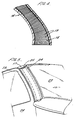
- FIG. 5 there is a schematic illustration of how the pillar 17 will look from the interior of the vehicle in use.
- the pillar 17 is located between the windscreen 22 and the door frame 23 of a door 26.
- An interior surface is provided by a layer of ABS material 24 which is wrapped around the pillar 17.
- a crush tube 25 Enclosed and sandwiched between the pillar 17 and the outer layer of ABS material 24 is a crush tube 25.
- the crush tube 25 is typically a hollow corrugated tube of aluminium or of cardboard or of cardboard and aluminium.
- the crush tube 25 will be a hollow member.
- the crush tube 25 is located in such a position that it will prevent the head of an occupant of a land vehicle hitting directly the pillar 17 in the event of a vehicle collision.
- the crush tube 25 will deform to absorb impact energy when there is a crash.
Landscapes
- Engineering & Computer Science (AREA)
- Chemical & Material Sciences (AREA)
- Combustion & Propulsion (AREA)
- Transportation (AREA)
- Mechanical Engineering (AREA)
- Architecture (AREA)
- Structural Engineering (AREA)
- Body Structure For Vehicles (AREA)
- Separation Of Suspended Particles By Flocculating Agents (AREA)
- Cereal-Derived Products (AREA)
- Grain Derivatives (AREA)
Abstract
Description
Claims (19)
- A land vehicle having a pillar (16,17) which is a structural component of the vehicle and a pillar support structure (14), the pillar (16,17)being a distinct independent component not formed integrally with any surrounding components of the land vehicle, characterised in that the pillar (16,17) is secured in position by setting of a root portion of the pillar (16) in resinous material (20; 20A) provided in a cavity defined in the pillar support structure (14).
- A land vehicle as claimed in claim 1 wherein the resinous material (20A) comprises an epoxy resin.
- A land vehicle as claimed in claim 1 wherein the resinous material (20) comprises a polyurethane resin.
- A land vehicle as claimed in any one of the preceding claims wherein the resinous material (20) comprises hollow microspheres (21) dispersed in a resin.
- A land vehicle as claimed in claim 4 wherein the hollow microspheres (21) are glass microspheres.
- A land vehicle as claimed in any one of the preceding claims wherein the cavity has a constant cross-section along the length thereof and the pillar (16, 17) has a cross-section which varies along the length thereof.
- A land vehicle as claimed in any one of the preceding claims wherein the cavity has a principal axis and the pillar (16,17) is set at an angle to the principal axis.
- A land vehicle as claimed in any one of the preceding claims wherein the pillar (16, 17) comprises fibres (19) set in a resin matrix.
- A land vehicle as claimed in claim 8 wherein the pillar (16,17)has a core (18) of foamed material around which the fibres (19) are wound with the core (18) being encased by the resin matrix.
- A land vehicle as claimed in claim 8 or claim 9 wherein the fibres (19) are carbon fibres.
- A land vehicle as claimed in any one of claims 8 to 10 wherein the fibres (19) are braided fibres.
- A land vehicle as claimed in any one of the preceding claims wherein the land vehicle has an aluminium chassis and the pillar (16, 17) is an "A" pillar of the vehicle which is set in the cavity, the cavity being a cavity defined in the aluminium chassis.
- A land vehicle as claimed in any one of the preceding claims which has a pair of pillars (16,17) spaced apart one each side of a windscreen, the pair of pillars (16,17) being secured in position one each in a pair of spaced apart cavities by setting root portions of the pillars in resinous material (20; 20A) provided in the cavities, the pillars (16, 17) providing crush resistance in the event of the land vehicle rolling over.
- A land vehicle as claimed in any one of the preceding claims comprising additionally a crush tube (25) mounted adjacent the pillar (16, 17) and covered in a flexible material (24), the crush tube (25) being located to prevent a head of an occupant of the land vehicle hitting directly the pillar (16,17) in the event of a vehicle collision, the crush tube (25) deforming to absorb impact energy in such an event.
- A land vehicle as claimed in claim 14 wherein the crush tube (25) is an aluminium crush tube.
- A land vehicle as claimed in claim 14 wherein the crush tube (25) is a cardboard crush tube.
- A land vehicle as claimed in any one of claims 14 to 16 wherein the crush tube (25)is covered by a sheet (24) of ABS plastic material.
- A method of manufacture of a land vehicle as claimed in any one of the preceding claims wherein the pillar (16,17) is positioned with the root portion thereof extending into the cavity in the pillar support structure (14);
the resinous material (20; 20A) in liquid state is poured into the cavity surrounding the root portion of the pillar (16,17);
the resinous material (20; 20A) is cured; and
the cured resinous material (20; 20A) secures the pillar (16,17) in position. - A method of manufacture of a land vehicle as claimed in claim 18 which comprises the steps of:forming core (18) of foamed material in a desired shape with a cross-section which varies lengthwise along the core;winding fibres (19)around the core (18) of foamed material;setting the wound fibres (19) in a resin matrix and thereby encasing the core of foamed material (18).
Applications Claiming Priority (3)
| Application Number | Priority Date | Filing Date | Title |
|---|---|---|---|
| GB0019478A GB2365391B (en) | 2000-08-08 | 2000-08-08 | Land vehicle |
| GB0019478 | 2000-08-08 | ||
| PCT/GB2001/003571 WO2002012053A1 (en) | 2000-08-08 | 2001-08-08 | Pillar support structure in a land vehicle |
Publications (2)
| Publication Number | Publication Date |
|---|---|
| EP1233899A1 EP1233899A1 (en) | 2002-08-28 |
| EP1233899B1 true EP1233899B1 (en) | 2003-07-16 |
Family
ID=9897225
Family Applications (1)
| Application Number | Title | Priority Date | Filing Date |
|---|---|---|---|
| EP01954204A Expired - Lifetime EP1233899B1 (en) | 2000-08-08 | 2001-08-08 | Pillar support structure in a land vehicle |
Country Status (7)
| Country | Link |
|---|---|
| US (1) | US6619715B2 (en) |
| EP (1) | EP1233899B1 (en) |
| AT (1) | ATE245104T1 (en) |
| AU (1) | AU2001276548A1 (en) |
| DE (1) | DE60100470T2 (en) |
| GB (1) | GB2365391B (en) |
| WO (1) | WO2002012053A1 (en) |
Families Citing this family (9)
| Publication number | Priority date | Publication date | Assignee | Title |
|---|---|---|---|---|
| DE10229401A1 (en) * | 2002-06-29 | 2004-01-22 | Dr.Ing.H.C. F. Porsche Ag | Structure for a vehicle, in particular a passenger car |
| AT8606U1 (en) * | 2005-03-21 | 2006-10-15 | Magna Steyr Fahrzeugtechnik Ag | MOTOR VEHICLE WITH MODULAR BUILT-ON BODY |
| DE102007025632A1 (en) * | 2007-06-01 | 2008-12-04 | Audi Ag | Fiber composite profile and vehicle window frame |
| DE102007053353B4 (en) * | 2007-10-30 | 2017-06-08 | Deutsches Zentrum für Luft- und Raumfahrt e.V. | Body pillar for vehicles and vehicle body |
| DE102008032344B4 (en) * | 2008-07-09 | 2021-01-21 | Bayerische Motoren Werke Aktiengesellschaft | Assembly, especially for a vehicle body |
| KR101755706B1 (en) * | 2011-09-05 | 2017-07-10 | 현대자동차주식회사 | Cowl cross structure |
| EP3983280B1 (en) * | 2019-07-04 | 2024-11-13 | Plasan Sasa Ltd | Vehicle body in white and method for its manufacturing |
| KR102807543B1 (en) * | 2019-12-17 | 2025-05-13 | 현대자동차주식회사 | Vehicle body assembly structure |
| KR20230063577A (en) * | 2021-11-02 | 2023-05-09 | 현대자동차주식회사 | Body for vehicle |
Family Cites Families (24)
| Publication number | Priority date | Publication date | Assignee | Title |
|---|---|---|---|---|
| US3127213A (en) * | 1964-03-31 | Automobile roof mounting | ||
| GB526159A (en) * | 1938-03-09 | 1940-09-11 | Audi Ag | Improvements in or relating to vehicle bodies |
| FR1117949A (en) * | 1954-01-19 | 1956-05-29 | Daimler Benz Ag | Car superstructure, in particular for passenger motor cars |
| IT1165208B (en) * | 1979-05-25 | 1987-04-22 | Fiat Auto Spa | SUPPORTING FRAME FOR MOTOR VEHICLES |
| DE3514544A1 (en) | 1985-03-14 | 1986-09-25 | Josef Gartner & Co, 8883 Gundelfingen | Composite profile |
| US4730870A (en) * | 1986-03-14 | 1988-03-15 | American Motors Corporation | Modular vehicle construction and assembly method |
| JPH02200580A (en) * | 1989-01-30 | 1990-08-08 | Mazda Motor Corp | Body structure for automobile |
| US4917435A (en) * | 1989-05-23 | 1990-04-17 | Ford Motor Company | Truck cab construction |
| DE4018592A1 (en) * | 1990-06-09 | 1991-12-12 | Porsche Ag | BODY FOR A MOTOR VEHICLE, ESPECIALLY A PASSENGER VEHICLE |
| DE4040946C1 (en) * | 1990-12-20 | 1992-03-05 | Audi Ag, 8070 Ingolstadt, De | |
| DE4138370A1 (en) * | 1990-12-20 | 1992-06-25 | Audi Ag | Central column for motor vehicle - comprises two successive extrusions in lengthwise direction and including acute angle |
| DE4409466A1 (en) * | 1993-03-20 | 1994-10-06 | Strobel Martin Dipl Designer | vehicle body |
| GB2293798B (en) * | 1994-10-07 | 1998-03-04 | Toyota Motor Co Ltd | Occupant protecting structures of vehicle body upper portions |
| SE503705C2 (en) * | 1994-10-25 | 1996-08-05 | Volvo Ab | Load-bearing structure for use in a vehicle body |
| DE19519354A1 (en) * | 1995-05-26 | 1996-11-28 | Porsche Ag | Body structure for road vehicle |
| JPH11507609A (en) * | 1995-06-06 | 1999-07-06 | アルミナム カンパニー オブ アメリカ | How to join structural elements |
| US5564744A (en) * | 1995-08-30 | 1996-10-15 | Davidson Textron Inc. | Energy absorbent interior trim for vehicle |
| JPH1029482A (en) * | 1996-07-15 | 1998-02-03 | Ootsuka:Kk | Impact energy absorber |
| US5884962A (en) * | 1996-09-12 | 1999-03-23 | Prince Corporation | Impact absorption member |
| GB2317858A (en) | 1996-10-03 | 1998-04-08 | Rover Group | Vehicle body structure |
| US6302478B1 (en) * | 1997-10-16 | 2001-10-16 | Cosma International Inc. | Hydroformed space frame joints therefor |
| JP3498614B2 (en) * | 1999-01-29 | 2004-02-16 | マツダ株式会社 | Vehicle body structure |
| US6296301B1 (en) * | 1999-12-21 | 2001-10-02 | Daimlerchrysler Corporation | Motor vehicle body structure using a woven fiber |
| US6493920B1 (en) * | 2000-09-07 | 2002-12-17 | Ford Global Technologies, Inc. | Method of assembling a vehicle from preassembled modular components |
-
2000
- 2000-08-08 GB GB0019478A patent/GB2365391B/en not_active Revoked
-
2001
- 2001-08-08 US US10/203,309 patent/US6619715B2/en not_active Expired - Lifetime
- 2001-08-08 DE DE60100470T patent/DE60100470T2/en not_active Expired - Lifetime
- 2001-08-08 AT AT01954204T patent/ATE245104T1/en not_active IP Right Cessation
- 2001-08-08 WO PCT/GB2001/003571 patent/WO2002012053A1/en not_active Ceased
- 2001-08-08 EP EP01954204A patent/EP1233899B1/en not_active Expired - Lifetime
- 2001-08-08 AU AU2001276548A patent/AU2001276548A1/en not_active Abandoned
Also Published As
| Publication number | Publication date |
|---|---|
| GB2365391B (en) | 2002-09-04 |
| ATE245104T1 (en) | 2003-08-15 |
| WO2002012053A1 (en) | 2002-02-14 |
| US6619715B2 (en) | 2003-09-16 |
| DE60100470T2 (en) | 2004-06-09 |
| EP1233899A1 (en) | 2002-08-28 |
| AU2001276548A1 (en) | 2002-02-18 |
| GB2365391A (en) | 2002-02-20 |
| DE60100470D1 (en) | 2003-08-21 |
| GB0019478D0 (en) | 2000-09-27 |
| US20030011206A1 (en) | 2003-01-16 |
Similar Documents
| Publication | Publication Date | Title |
|---|---|---|
| EP1060056B1 (en) | Three dimensional composite joint reinforcement for an automotive vehicle | |
| EP0787089B2 (en) | Stress-bearing assembly | |
| EP1153824A2 (en) | Composite laminate beam for automotive body construction | |
| US5884960A (en) | Reinforced door beam | |
| EP1031467B2 (en) | I-section automotive bumper formed from mineral-filled glass mat thermoplastic (gmt) composite | |
| US4978562A (en) | Composite tubular door beam reinforced with a syntactic foam core localized at the mid-span of the tube | |
| US20080048462A1 (en) | Thermoplastic composite bumper system | |
| US5967592A (en) | Hollow FRP bumper | |
| EP1628857B1 (en) | Bumper energy absorber and method of fabricating and assembling the same | |
| EP0618128B1 (en) | Lightweight road vehicle with load-bearing structure | |
| CN114763183B (en) | Locally reinforced foam-filled composite component for a vehicle body structure and method for the production thereof | |
| US6619715B2 (en) | Pillar support structure in a land vehicle | |
| US6168226B1 (en) | Composite laminate automotive structures | |
| CN114852180A (en) | Fiber-reinforced polymer composite component for a vehicle body structure and method for the production thereof | |
| CA2424041A1 (en) | Hydroform structural reinforcement system | |
| CN102348595A (en) | Reinforced foam vehicle chassis | |
| CA2320059A1 (en) | Lightweight laminate reinforcing web | |
| US3415568A (en) | Vehicle underbody of sandwich construction | |
| GB2552852A (en) | A monocoque structure | |
| US20090295195A1 (en) | Car frame featuring rtm-technology modules of compsite material | |
| KR102948573B1 (en) | Method for Manufacturing of the Light Weight Cowl cross bar for vehicle | |
| US20030218326A1 (en) | Tubular honeycomb articles for use in energy absorption | |
| EP0625104B1 (en) | High performance vehicle bumper | |
| EP1514738B1 (en) | Method for designing and manufacturing an I-section automotive bumper formed from mineral-filled glass mat thermoplastic (gmt) composite | |
| WO1997015472A1 (en) | Molded bumper system with reinforcement beam |
Legal Events
| Date | Code | Title | Description |
|---|---|---|---|
| PUAI | Public reference made under article 153(3) epc to a published international application that has entered the european phase |
Free format text: ORIGINAL CODE: 0009012 |
|
| 17P | Request for examination filed |
Effective date: 20020522 |
|
| AK | Designated contracting states |
Kind code of ref document: A1 Designated state(s): AT BE CH CY DE DK ES FI FR GB GR IE IT LI LU MC NL PT SE TR |
|
| AX | Request for extension of the european patent |
Free format text: AL;LT;LV;MK;RO;SI |
|
| GRAH | Despatch of communication of intention to grant a patent |
Free format text: ORIGINAL CODE: EPIDOS IGRA |
|
| GRAH | Despatch of communication of intention to grant a patent |
Free format text: ORIGINAL CODE: EPIDOS IGRA |
|
| GRAA | (expected) grant |
Free format text: ORIGINAL CODE: 0009210 |
|
| AK | Designated contracting states |
Designated state(s): AT BE CH CY DE DK ES FI FR GB GR IE IT LI LU MC NL PT SE TR |
|
| PG25 | Lapsed in a contracting state [announced via postgrant information from national office to epo] |
Ref country code: AT Free format text: LAPSE BECAUSE OF FAILURE TO SUBMIT A TRANSLATION OF THE DESCRIPTION OR TO PAY THE FEE WITHIN THE PRESCRIBED TIME-LIMIT Effective date: 20030716 Ref country code: IT Free format text: LAPSE BECAUSE OF FAILURE TO SUBMIT A TRANSLATION OF THE DESCRIPTION OR TO PAY THE FEE WITHIN THE PRESCRIBED TIME-LIMIT;WARNING: LAPSES OF ITALIAN PATENTS WITH EFFECTIVE DATE BEFORE 2007 MAY HAVE OCCURRED AT ANY TIME BEFORE 2007. THE CORRECT EFFECTIVE DATE MAY BE DIFFERENT FROM THE ONE RECORDED. Effective date: 20030716 Ref country code: FI Free format text: LAPSE BECAUSE OF FAILURE TO SUBMIT A TRANSLATION OF THE DESCRIPTION OR TO PAY THE FEE WITHIN THE PRESCRIBED TIME-LIMIT Effective date: 20030716 Ref country code: BE Free format text: LAPSE BECAUSE OF FAILURE TO SUBMIT A TRANSLATION OF THE DESCRIPTION OR TO PAY THE FEE WITHIN THE PRESCRIBED TIME-LIMIT Effective date: 20030716 Ref country code: TR Free format text: LAPSE BECAUSE OF FAILURE TO SUBMIT A TRANSLATION OF THE DESCRIPTION OR TO PAY THE FEE WITHIN THE PRESCRIBED TIME-LIMIT Effective date: 20030716 Ref country code: NL Free format text: LAPSE BECAUSE OF FAILURE TO SUBMIT A TRANSLATION OF THE DESCRIPTION OR TO PAY THE FEE WITHIN THE PRESCRIBED TIME-LIMIT Effective date: 20030716 Ref country code: CH Free format text: LAPSE BECAUSE OF FAILURE TO SUBMIT A TRANSLATION OF THE DESCRIPTION OR TO PAY THE FEE WITHIN THE PRESCRIBED TIME-LIMIT Effective date: 20030716 Ref country code: LI Free format text: LAPSE BECAUSE OF FAILURE TO SUBMIT A TRANSLATION OF THE DESCRIPTION OR TO PAY THE FEE WITHIN THE PRESCRIBED TIME-LIMIT Effective date: 20030716 |
|
| REG | Reference to a national code |
Ref country code: GB Ref legal event code: FG4D |
|
| REG | Reference to a national code |
Ref country code: CH Ref legal event code: EP |
|
| PG25 | Lapsed in a contracting state [announced via postgrant information from national office to epo] |
Ref country code: LU Free format text: LAPSE BECAUSE OF NON-PAYMENT OF DUE FEES Effective date: 20030808 Ref country code: CY Free format text: LAPSE BECAUSE OF FAILURE TO SUBMIT A TRANSLATION OF THE DESCRIPTION OR TO PAY THE FEE WITHIN THE PRESCRIBED TIME-LIMIT Effective date: 20030808 Ref country code: IE Free format text: LAPSE BECAUSE OF NON-PAYMENT OF DUE FEES Effective date: 20030808 |
|
| REG | Reference to a national code |
Ref country code: IE Ref legal event code: FG4D |
|
| REF | Corresponds to: |
Ref document number: 60100470 Country of ref document: DE Date of ref document: 20030821 Kind code of ref document: P |
|
| PG25 | Lapsed in a contracting state [announced via postgrant information from national office to epo] |
Ref country code: MC Free format text: LAPSE BECAUSE OF NON-PAYMENT OF DUE FEES Effective date: 20030831 |
|
| PG25 | Lapsed in a contracting state [announced via postgrant information from national office to epo] |
Ref country code: GR Free format text: LAPSE BECAUSE OF FAILURE TO SUBMIT A TRANSLATION OF THE DESCRIPTION OR TO PAY THE FEE WITHIN THE PRESCRIBED TIME-LIMIT Effective date: 20031016 Ref country code: SE Free format text: LAPSE BECAUSE OF FAILURE TO SUBMIT A TRANSLATION OF THE DESCRIPTION OR TO PAY THE FEE WITHIN THE PRESCRIBED TIME-LIMIT Effective date: 20031016 Ref country code: DK Free format text: LAPSE BECAUSE OF FAILURE TO SUBMIT A TRANSLATION OF THE DESCRIPTION OR TO PAY THE FEE WITHIN THE PRESCRIBED TIME-LIMIT Effective date: 20031016 |
|
| PG25 | Lapsed in a contracting state [announced via postgrant information from national office to epo] |
Ref country code: ES Free format text: LAPSE BECAUSE OF FAILURE TO SUBMIT A TRANSLATION OF THE DESCRIPTION OR TO PAY THE FEE WITHIN THE PRESCRIBED TIME-LIMIT Effective date: 20031027 |
|
| NLV1 | Nl: lapsed or annulled due to failure to fulfill the requirements of art. 29p and 29m of the patents act | ||
| PG25 | Lapsed in a contracting state [announced via postgrant information from national office to epo] |
Ref country code: PT Free format text: LAPSE BECAUSE OF FAILURE TO SUBMIT A TRANSLATION OF THE DESCRIPTION OR TO PAY THE FEE WITHIN THE PRESCRIBED TIME-LIMIT Effective date: 20031216 |
|
| LTIE | Lt: invalidation of european patent or patent extension |
Effective date: 20030716 |
|
| REG | Reference to a national code |
Ref country code: CH Ref legal event code: PL |
|
| ET | Fr: translation filed | ||
| PLBE | No opposition filed within time limit |
Free format text: ORIGINAL CODE: 0009261 |
|
| STAA | Information on the status of an ep patent application or granted ep patent |
Free format text: STATUS: NO OPPOSITION FILED WITHIN TIME LIMIT |
|
| REG | Reference to a national code |
Ref country code: IE Ref legal event code: MM4A |
|
| 26N | No opposition filed |
Effective date: 20040419 |
|
| REG | Reference to a national code |
Ref country code: GB Ref legal event code: 732E |
|
| REG | Reference to a national code |
Ref country code: FR Ref legal event code: GC |
|
| REG | Reference to a national code |
Ref country code: DE Ref legal event code: R082 Ref document number: 60100470 Country of ref document: DE Representative=s name: MOSER & GOETZE PATENTANWAELTE, DE Ref country code: DE Ref legal event code: R082 Ref document number: 60100470 Country of ref document: DE Representative=s name: MOSER GOETZE & PARTNER PATENTANWAELTE MBB, DE |
|
| REG | Reference to a national code |
Ref country code: FR Ref legal event code: RG Effective date: 20120227 |
|
| REG | Reference to a national code |
Ref country code: FR Ref legal event code: PLFP Year of fee payment: 16 |
|
| REG | Reference to a national code |
Ref country code: FR Ref legal event code: PLFP Year of fee payment: 17 |
|
| REG | Reference to a national code |
Ref country code: FR Ref legal event code: PLFP Year of fee payment: 18 |
|
| PGFP | Annual fee paid to national office [announced via postgrant information from national office to epo] |
Ref country code: FR Payment date: 20190815 Year of fee payment: 19 Ref country code: DE Payment date: 20190830 Year of fee payment: 19 |
|
| PGFP | Annual fee paid to national office [announced via postgrant information from national office to epo] |
Ref country code: GB Payment date: 20190814 Year of fee payment: 19 |
|
| REG | Reference to a national code |
Ref country code: DE Ref legal event code: R119 Ref document number: 60100470 Country of ref document: DE |
|
| GBPC | Gb: european patent ceased through non-payment of renewal fee |
Effective date: 20200808 |
|
| PG25 | Lapsed in a contracting state [announced via postgrant information from national office to epo] |
Ref country code: FR Free format text: LAPSE BECAUSE OF NON-PAYMENT OF DUE FEES Effective date: 20200831 Ref country code: DE Free format text: LAPSE BECAUSE OF NON-PAYMENT OF DUE FEES Effective date: 20210302 |
|
| PG25 | Lapsed in a contracting state [announced via postgrant information from national office to epo] |
Ref country code: GB Free format text: LAPSE BECAUSE OF NON-PAYMENT OF DUE FEES Effective date: 20200808 |