EP1233530A1 - Terminal mobile de réseau de radiotéléphonie à deux chaines d'émission et de réception et deux antennes - Google Patents
Terminal mobile de réseau de radiotéléphonie à deux chaines d'émission et de réception et deux antennes Download PDFInfo
- Publication number
- EP1233530A1 EP1233530A1 EP02290352A EP02290352A EP1233530A1 EP 1233530 A1 EP1233530 A1 EP 1233530A1 EP 02290352 A EP02290352 A EP 02290352A EP 02290352 A EP02290352 A EP 02290352A EP 1233530 A1 EP1233530 A1 EP 1233530A1
- Authority
- EP
- European Patent Office
- Prior art keywords
- chain
- reception
- terminal according
- antenna
- transmission
- Prior art date
- Legal status (The legal status is an assumption and is not a legal conclusion. Google has not performed a legal analysis and makes no representation as to the accuracy of the status listed.)
- Granted
Links
- 230000005540 biological transmission Effects 0.000 claims description 27
- 230000005764 inhibitory process Effects 0.000 claims description 11
- 230000003071 parasitic effect Effects 0.000 claims description 9
- 230000003321 amplification Effects 0.000 claims description 4
- 238000003199 nucleic acid amplification method Methods 0.000 claims description 4
- 238000000034 method Methods 0.000 description 5
- 244000045947 parasite Species 0.000 description 5
- 230000002238 attenuated effect Effects 0.000 description 2
- 238000001914 filtration Methods 0.000 description 2
- 230000010363 phase shift Effects 0.000 description 2
- 230000017105 transposition Effects 0.000 description 2
- 230000006978 adaptation Effects 0.000 description 1
- 230000002457 bidirectional effect Effects 0.000 description 1
- 230000001413 cellular effect Effects 0.000 description 1
- 230000000694 effects Effects 0.000 description 1
- 230000008030 elimination Effects 0.000 description 1
- 238000003379 elimination reaction Methods 0.000 description 1
- 238000000605 extraction Methods 0.000 description 1
- 239000003112 inhibitor Substances 0.000 description 1
- 238000000926 separation method Methods 0.000 description 1
- 238000011144 upstream manufacturing Methods 0.000 description 1
Images
Classifications
-
- H—ELECTRICITY
- H04—ELECTRIC COMMUNICATION TECHNIQUE
- H04B—TRANSMISSION
- H04B1/00—Details of transmission systems, not covered by a single one of groups H04B3/00 - H04B13/00; Details of transmission systems not characterised by the medium used for transmission
- H04B1/38—Transceivers, i.e. devices in which transmitter and receiver form a structural unit and in which at least one part is used for functions of transmitting and receiving
- H04B1/40—Circuits
- H04B1/50—Circuits using different frequencies for the two directions of communication
- H04B1/52—Hybrid arrangements, i.e. arrangements for transition from single-path two-direction transmission to single-direction transmission on each of two paths or vice versa
- H04B1/525—Hybrid arrangements, i.e. arrangements for transition from single-path two-direction transmission to single-direction transmission on each of two paths or vice versa with means for reducing leakage of transmitter signal into the receiver
Definitions
- the present invention relates to radio transmissions by terminals radiotelephony mobiles.
- a mobile radiotelephone terminal communicates with the others by a bidirectional link, for which it has a frequency for each direction of transmission.
- the terminal sender is a powerful disruptor for its receiver.
- the first technique is to operate the terminal in the work-study program, i.e. to cyclically inhibit the receiver and the transmitter.
- the second technique is to operate the terminal in full-duplex but separating the transmission and reception chains connected to the antenna.
- a switcher called duplexer which transmits energy from the transmitter exclusively to the antenna and which transmits the energy captured by the antenna exclusively to the receiver.
- the electrical balance of the duplexer, to reach the separation power or decoupling desired between channels, requires that the antenna maintains an adapted impedance, of determined value, in the transmit and receive frequency bands.
- the antenna In practice, to achieve this goal, the antenna must also remain suitable in the unused band separating the useful bands.
- the antenna must therefore be broadband, as far as concerns its adaptation, that is to say relatively complex and bulky.
- the cost and volume of the duplexer are otherwise high and, in addition, it presents losses which it is necessary compensate by an emission at increased level, which impairs the energy autonomy of the terminal.
- the present invention relates to this second technique, of full-duplex operation, and aims to overcome the above drawbacks related to duplexer.
- the invention relates to a mobile network terminal radiotelephony comprising radio means comprising a transmission chain and a reception chain arranged to operate in full-duplex in two bands of respective frequencies, characterized in that each chain has an antenna dedicated.
- the plaintiff's merit is to have gone against the prejudice according to which, to solve the problem of protecting a reception chain against radio signals from a transmission chain, it was necessary to provide a duplexer for decoupling channels inside the radio interface of the terminal.
- the Applicant has in fact posed the above problem differently, that is to say that it considered that the real problem, in general, was to prevent signals generated by the transmission chain reach the output of the reception chain, and that solutions without a duplexer should be considered.
- each antenna can be of limited size since it only processes its useful frequency band.
- the radio means comprise means arranged to inhibit reception of spurious emission signals in a reception frequency band and the emission chain comprises means for controlling the inhibition means.
- the inhibition means include elimination filtering harmonics of a frequency band of the transmission chain.
- reception chain has non-linear elements likely to carry out a frequency transposition by a parasitic demodulation, these elements do not receive a harmonic signal which could be transposed to the frequency of reception.
- the means of inhibition comprise, in the chain transmission, means for deriving, on the reception chain, transmission signals parasites and, in the reception chain, means for opposing these transmission signals parasites derived from the parasitic emission signals received by the antenna of the chain reception.
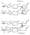
- Figure 1 shows two radio channels of a mobile terminal cellular radiotelephony, the reference 1 designating a chain of emission and the reference 2 a reception chain.
- the transmission chain 1 operates here in a range or band of 60 MHz, centered on 1950 MHz, and the reception chain 2 operates here in a 60 MHz band centered on 2140 MHz.
- the transmission chain 1 comprises a conventional modulator 11 providing a carrier in the low band considered, modulated by data or bits to be transmitted.
- the signal from the modulator 11 passes through an amplifier 12 followed by a filter 13 separating channels, attenuating the parasites emitted in the band, here high, of the reception chain 2. It here is therefore a low-pass filter which transmits at 1980 MHz and attenuates at 2110 MHz.
- the filter 13 could have been provided with the band pass type or the band cutter and then tuned on the receiving frequency band.
- a dedicated transmission antenna 19 is connected at the output of the low-pass filter 13.
- the reception chain 2 includes a dedicated reception antenna 29 connected, here indirectly, to a bandpass input filter 23, tuned to the reception band, controlling an amplifier 22, with low noise input stage.
- Amplifier 22 controls a conventional demodulator 21 providing a stream of bits extracted from the signal which has received by antenna 29.
- Channels 1 and 2 are linked to each other to inhibit the reception of parasitic emission signals in the reception band.
- the antennas 19 and 29 are indeed close to each other, since it is of a portable terminal, and, even if the filter 13 has good filtering efficiency, the attenuated parasites which it transmits to the transmitting antenna 19 are received, without attenuation radio transmission, by the receiving antenna 29.
- the reception chain 2 includes a circuit analog 24 with two inputs, connected at output to the input of bandpass filter 23 and connected by a first input to antenna 29 and, via a second input, to a channel derived from the transmission chain 1.
- the circuit 24 is here a low noise amplifier.
- the above derivative channel consists of an adjustable phase shifter 17 in series with an attenuator 18, receiving part of the signal applied to the antenna 19, sampled by a capacitive microstrip coupler 14.
- the inhibition derivative channel 17, 18 is adjusted to provide a signal of the same amplitude that the parasitic emission signal picked up by the reception antenna 29.
- the muting signal is subtracted from the signal received, i.e. it is carried out the addition of two opposite signals, of equal amplitudes and displaced by 180 degrees.
- the 180-degree phase shift can be achieved in the phase shifter 17, and the amplifier 24 is then an adder, or else the phase shifter 17 is set to a zero phase shift relative to the interference from the receiving antenna 29 and the amplifier 24 is then a subtractor, as illustrated in figure 1.
- the transmission chain 3 comprises, in the direction of propagation of signals, modulator 11, amplifier 12, bandpass filter 13, coupler tap 14 and antenna 19.
- the reception chain 4 includes the antenna 29 directly connected to the filter bandpass 23 followed by amplifier 22 and demodulator 21.
- An inhibitor coupler 44 with microstrip, is capacitively coupled to the demodulator 44 input link to inject an inhibition signal from the broadcast channel 3.
- the muting coupler 44 has, overall, a function similar to that of the amplifier 24. It is connected to the extraction coupler 14 by a transposition circuit 16 frequency which provides a signal to inhibit radio interference, this inhibition being performed after amplification in the amplifier 22.
- the associated adjustment circuits 17, 18 were not drawn.
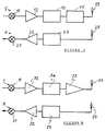
- FIG. 3 shows a transmission chain 5 and a reception chain 6.
- the transmission chain 5 comprises, in order, the modulator 11, the amplifier 12, the filter low pass 13, antenna 19 and furthermore a rejection filter, notch, 15 in series between the modulator 11 and the antenna 19, here connecting the low-pass filter 13 to the latter.
- the notch filter 15 is here with frequency adjustable by programming.
- the notch filter 15 attenuates the noise created by the amplifier at the frequency reception.
- the notch filter 15 consists of stages of resonant circuits, inductance and capacitance, or equivalent circuits (dielectric resonators, ...), for cover at least the required 60 MHz in total by shifting the resonant frequency of the filtered.
- Each stage has a conventional inductance associated with a capacitive diode variable polarized by a DC voltage for adjusting the capacity, setting coming from a filter programming processor 15.
- the programming processor is connected to the radio block to teleprogram filter 15 from the telephone network.
- the reception chain 6 comprises the antenna 29, connected directly to the filter bandpass 23 controlling the amplifier 22 followed by the demodulator 21. These two last elements are likely to have non-linearities and therefore to have an effect parasitic demodulator transposing, in the reception band, part of the energy of a spurious signal.
- the notch filter 15 is therefore adjusted to attenuate the signals transmitted to the receiver reception frequency.
- the attenuated frequency band is adjusted accordingly reception frequency.
Landscapes
- Engineering & Computer Science (AREA)
- Computer Networks & Wireless Communication (AREA)
- Signal Processing (AREA)
- Transceivers (AREA)
Abstract
Description
Claims (10)
- Terminal mobile de réseau de radiotéléphonie comportant des moyens radio comprenant une chaíne d'émission (1) et une chaíne de réception (2) agencées pour fonctionner en full-duplex dans deux bandes de fréquences respectives, caractérisé par le fait que chaque chaíne (1, 2) comporte une antenne dédiée (19, 29).
- Terminal selon la revendication 1, dans lequel les moyens radio comportent des moyens (13, 15, 16, 17, 24, 44) agencés pour inhiber la réception de signaux d'émission parasites dans une bande de fréquences de réception.
- Terminal selon la revendication 2, dans lequel la chaíne d'émission (1) comporte des moyens (14) de commande des moyens d'inhibition (13, 15, 16, 17, 24, 44).
- Terminal selon la revendication 3, dans lequel au moins une partie des moyens d'inhibition (13, 15) est montée en série dans la chaíne d'émission (1).
- Terminal selon la revendication 4, dans lequel les moyens d'inhibition comportent un filtre coupe-bande (13) accordé sur une plage de fréquences de la chaíne de réception (2).
- Terminal selon l'une des revendications 4 et 5, dans lequel les moyens d'inhibition comportent un filtre (15) d'élimination d'harmoniques d'une bande de fréquences de la chaíne d'émission (1).
- Terminal selon l'une des revendications 2 à 6, dans lequel les moyens d'inhibition comportent, dans la chaíne d'émission (1), des moyens (14, 16, 17) pour dériver, sur la chaíne de réception (2), des signaux d'émission parasites et, dans la chaíne de réception (2), des moyens (24, 44) pour opposer ces signaux d'émission parasites dérivés aux signaux d'émission parasites reçus par l'antenne (29) de la chaíne de réception (2).
- Terminal selon la revendication 7, dans lequel les moyens de dérivation comportent un atténuateur (18) et un déphaseur (17).
- Terminal selon l'une des revendications 7 et 8, dans lequel les moyens (24) d'opposition des signaux parasites dérivés sur la chaíne de réception (2) et reçus par son antenne (29) constituent l'étage d'entrée de cette chaíne de réception (2).
- Terminal selon la revendication 1, dans lequel la chaíne d'émission (7) comporte une chaíne d'amplification (32, 33) dans laquelle est inséré un filtre passe-bande (34).
Applications Claiming Priority (2)
| Application Number | Priority Date | Filing Date | Title |
|---|---|---|---|
| FR0102058 | 2001-02-15 | ||
| FR0102058A FR2820930B1 (fr) | 2001-02-15 | 2001-02-15 | Terminal mobile de reseau de radiotelephonie a deux chaines d'emission et de reception et deux antennes |
Publications (2)
| Publication Number | Publication Date |
|---|---|
| EP1233530A1 true EP1233530A1 (fr) | 2002-08-21 |
| EP1233530B1 EP1233530B1 (fr) | 2013-11-06 |
Family
ID=8860048
Family Applications (1)
| Application Number | Title | Priority Date | Filing Date |
|---|---|---|---|
| EP02290352.0A Expired - Lifetime EP1233530B1 (fr) | 2001-02-15 | 2002-02-13 | Terminal mobile de réseau de radiotéléphonie à deux chaines d'émission et de réception et deux antennes |
Country Status (2)
| Country | Link |
|---|---|
| EP (1) | EP1233530B1 (fr) |
| FR (1) | FR2820930B1 (fr) |
Cited By (3)
| Publication number | Priority date | Publication date | Assignee | Title |
|---|---|---|---|---|
| GB2435985A (en) * | 2006-03-07 | 2007-09-12 | Motorola Inc | A terminal having multiple antennas and receiver chains |
| WO2008107812A1 (fr) * | 2007-03-05 | 2008-09-12 | Nxp B.V. | Système et procédé de traitement d'un signal reçu |
| EP3042451B1 (fr) * | 2013-11-25 | 2019-05-01 | Raytheon Company | Annuleur à action directe |
Citations (3)
| Publication number | Priority date | Publication date | Assignee | Title |
|---|---|---|---|---|
| US5444864A (en) * | 1992-12-22 | 1995-08-22 | E-Systems, Inc. | Method and apparatus for cancelling in-band energy leakage from transmitter to receiver |
| GB2329554A (en) * | 1997-07-28 | 1999-03-24 | Roke Manor Research | Isolation of transmitted signal from received signal |
| US6169912B1 (en) * | 1999-03-31 | 2001-01-02 | Pericom Semiconductor Corp. | RF front-end with signal cancellation using receiver signal to eliminate duplexer for a cordless phone |
Family Cites Families (2)
| Publication number | Priority date | Publication date | Assignee | Title |
|---|---|---|---|---|
| CA2127189A1 (fr) * | 1993-08-06 | 1995-02-07 | James John Crnkovic | Appareil et methode pour attenuer les signaux parasites dans un emetteur-recepteur radio |
| GB9423027D0 (en) * | 1994-11-15 | 1995-01-04 | Univ Bristol | Full-duplex radio transmitter/receiver |
-
2001
- 2001-02-15 FR FR0102058A patent/FR2820930B1/fr not_active Expired - Fee Related
-
2002
- 2002-02-13 EP EP02290352.0A patent/EP1233530B1/fr not_active Expired - Lifetime
Patent Citations (3)
| Publication number | Priority date | Publication date | Assignee | Title |
|---|---|---|---|---|
| US5444864A (en) * | 1992-12-22 | 1995-08-22 | E-Systems, Inc. | Method and apparatus for cancelling in-band energy leakage from transmitter to receiver |
| GB2329554A (en) * | 1997-07-28 | 1999-03-24 | Roke Manor Research | Isolation of transmitted signal from received signal |
| US6169912B1 (en) * | 1999-03-31 | 2001-01-02 | Pericom Semiconductor Corp. | RF front-end with signal cancellation using receiver signal to eliminate duplexer for a cordless phone |
Cited By (6)
| Publication number | Priority date | Publication date | Assignee | Title |
|---|---|---|---|---|
| GB2435985A (en) * | 2006-03-07 | 2007-09-12 | Motorola Inc | A terminal having multiple antennas and receiver chains |
| GB2435985B (en) * | 2006-03-07 | 2008-04-02 | Motorola Inc | A terminal for use in a wireless communication system, a system including the terminal and a method of operation of the terminal |
| US8165545B2 (en) | 2006-03-07 | 2012-04-24 | Motorola Solutions, Inc. | Terminal for use in a wireless communication system and a method of operation thereof |
| WO2008107812A1 (fr) * | 2007-03-05 | 2008-09-12 | Nxp B.V. | Système et procédé de traitement d'un signal reçu |
| US8457568B2 (en) | 2007-03-05 | 2013-06-04 | Nxp B.V. | System and method for processing a received signal |
| EP3042451B1 (fr) * | 2013-11-25 | 2019-05-01 | Raytheon Company | Annuleur à action directe |
Also Published As
| Publication number | Publication date |
|---|---|
| FR2820930A1 (fr) | 2002-08-16 |
| EP1233530B1 (fr) | 2013-11-06 |
| FR2820930B1 (fr) | 2003-05-16 |
Similar Documents
| Publication | Publication Date | Title |
|---|---|---|
| EP0441500B1 (fr) | Emetteur-récepteur radio | |
| US20110134810A1 (en) | Module for use in mobile communication terminal and mobile communication terminal applying the same therein | |
| US6714775B1 (en) | Interference canceller | |
| CN105577259A (zh) | 具有可变增益放大器的分集接收机前端系统 | |
| US8649729B2 (en) | System and method for providing broadband interference and allowing communication therethrough | |
| HUP0200304A2 (en) | Integrated antenna coupler element | |
| CN105577206A (zh) | 具有相移部件的分集接收机前端系统 | |
| EP1178608A2 (fr) | Commutateur haute fréquence et appareil de communication sans fil utilisant celui-ci | |
| US8457685B1 (en) | Method and system for increasing efficiency in a radio front-end | |
| FR2897215A1 (fr) | Dispositif et procede d'annulation des interferences | |
| EP1233530B1 (fr) | Terminal mobile de réseau de radiotéléphonie à deux chaines d'émission et de réception et deux antennes | |
| US20080169878A1 (en) | Low loss combiner for narrowband and wideband rf signals | |
| EP1187317A2 (fr) | Emetteur et appareil de communication sans fil | |
| US6892056B1 (en) | Subscriber station with duplex antenna amplifier | |
| JP2004200853A (ja) | 高周波回路装置 | |
| CN213367767U (zh) | 一种罗兰-c信号接收一体机 | |
| FR2828624A1 (fr) | Systeme d'emission/reception pour telephone mobile multibande et multimode | |
| EP1189356B1 (fr) | Appareil communiquant multimode comportant un dispositif d'émission réception à plusieurs entrées | |
| EP1249889B1 (fr) | Filtre hyperfréquence à résonateur diélectrique | |
| KR101298129B1 (ko) | 트리플렉서를 이용한 삼중 대역 증폭기 | |
| EP1283600A1 (fr) | Système d'émission/réception pour téléphone mobile multibande et multimode | |
| FR2897740A1 (fr) | Circuit de suppression de signal telephonique,circuit de reception de diffusion numerique et appareil de reception de diffusion numerique portatif | |
| EP1037479B1 (fr) | Base de réseau radiotéléphonique local reliée à un réseau de radiotéléphonie cellulaire | |
| FR2828617A1 (fr) | Telephone mobile avec asservissement de puissance et procede associe | |
| FR2696889A3 (fr) | Coupleur d'antenne émettrice-réceptrice. |
Legal Events
| Date | Code | Title | Description |
|---|---|---|---|
| PUAI | Public reference made under article 153(3) epc to a published international application that has entered the european phase |
Free format text: ORIGINAL CODE: 0009012 |
|
| AK | Designated contracting states |
Kind code of ref document: A1 Designated state(s): AT BE CH CY DE DK ES FI FR GB GR IE IT LI LU MC NL PT SE TR |
|
| AX | Request for extension of the european patent |
Free format text: AL;LT;LV;MK;RO;SI |
|
| 17P | Request for examination filed |
Effective date: 20030221 |
|
| AKX | Designation fees paid |
Designated state(s): DE FR GB |
|
| RAP1 | Party data changed (applicant data changed or rights of an application transferred) |
Owner name: SAGEM COMMUNICATION |
|
| RAP1 | Party data changed (applicant data changed or rights of an application transferred) |
Owner name: SAGEM MOBILES |
|
| 17Q | First examination report despatched |
Effective date: 20110722 |
|
| RAP1 | Party data changed (applicant data changed or rights of an application transferred) |
Owner name: APPLE INC. |
|
| RIC1 | Information provided on ipc code assigned before grant |
Ipc: H04B 1/50 20060101AFI20130430BHEP Ipc: H04B 1/12 20060101ALI20130430BHEP Ipc: H04B 1/52 20060101ALI20130430BHEP |
|
| GRAP | Despatch of communication of intention to grant a patent |
Free format text: ORIGINAL CODE: EPIDOSNIGR1 |
|
| INTG | Intention to grant announced |
Effective date: 20130617 |
|
| GRAS | Grant fee paid |
Free format text: ORIGINAL CODE: EPIDOSNIGR3 |
|
| GRAA | (expected) grant |
Free format text: ORIGINAL CODE: 0009210 |
|
| AK | Designated contracting states |
Kind code of ref document: B1 Designated state(s): DE FR GB |
|
| REG | Reference to a national code |
Ref country code: GB Ref legal event code: FG4D Free format text: NOT ENGLISH |
|
| REG | Reference to a national code |
Ref country code: DE Ref legal event code: R096 Ref document number: 60245718 Country of ref document: DE Effective date: 20140102 |
|
| REG | Reference to a national code |
Ref country code: DE Ref legal event code: R097 Ref document number: 60245718 Country of ref document: DE |
|
| PLBE | No opposition filed within time limit |
Free format text: ORIGINAL CODE: 0009261 |
|
| STAA | Information on the status of an ep patent application or granted ep patent |
Free format text: STATUS: NO OPPOSITION FILED WITHIN TIME LIMIT |
|
| 26N | No opposition filed |
Effective date: 20140807 |
|
| REG | Reference to a national code |
Ref country code: DE Ref legal event code: R097 Ref document number: 60245718 Country of ref document: DE Effective date: 20140807 |
|
| REG | Reference to a national code |
Ref country code: FR Ref legal event code: ST Effective date: 20141031 |
|
| PG25 | Lapsed in a contracting state [announced via postgrant information from national office to epo] |
Ref country code: FR Free format text: LAPSE BECAUSE OF NON-PAYMENT OF DUE FEES Effective date: 20140228 |
|
| PGFP | Annual fee paid to national office [announced via postgrant information from national office to epo] |
Ref country code: DE Payment date: 20210202 Year of fee payment: 20 Ref country code: GB Payment date: 20210203 Year of fee payment: 20 |
|
| REG | Reference to a national code |
Ref country code: DE Ref legal event code: R071 Ref document number: 60245718 Country of ref document: DE |
|
| REG | Reference to a national code |
Ref country code: GB Ref legal event code: PE20 Expiry date: 20220212 |
|
| PG25 | Lapsed in a contracting state [announced via postgrant information from national office to epo] |
Ref country code: GB Free format text: LAPSE BECAUSE OF EXPIRATION OF PROTECTION Effective date: 20220212 |