EP1233498A2 - Permanent-Magnet motor-generator with voltage stabilizer - Google Patents
Permanent-Magnet motor-generator with voltage stabilizer Download PDFInfo
- Publication number
- EP1233498A2 EP1233498A2 EP01306373A EP01306373A EP1233498A2 EP 1233498 A2 EP1233498 A2 EP 1233498A2 EP 01306373 A EP01306373 A EP 01306373A EP 01306373 A EP01306373 A EP 01306373A EP 1233498 A2 EP1233498 A2 EP 1233498A2
- Authority
- EP
- European Patent Office
- Prior art keywords
- pole
- rotor
- permanent
- motor
- voltage
- Prior art date
- Legal status (The legal status is an assumption and is not a legal conclusion. Google has not performed a legal analysis and makes no representation as to the accuracy of the status listed.)
- Granted
Links
Images



Classifications
-
- B—PERFORMING OPERATIONS; TRANSPORTING
- B60—VEHICLES IN GENERAL
- B60K—ARRANGEMENT OR MOUNTING OF PROPULSION UNITS OR OF TRANSMISSIONS IN VEHICLES; ARRANGEMENT OR MOUNTING OF PLURAL DIVERSE PRIME-MOVERS IN VEHICLES; AUXILIARY DRIVES FOR VEHICLES; INSTRUMENTATION OR DASHBOARDS FOR VEHICLES; ARRANGEMENTS IN CONNECTION WITH COOLING, AIR INTAKE, GAS EXHAUST OR FUEL SUPPLY OF PROPULSION UNITS IN VEHICLES
- B60K6/00—Arrangement or mounting of plural diverse prime-movers for mutual or common propulsion, e.g. hybrid propulsion systems comprising electric motors and internal combustion engines
- B60K6/20—Arrangement or mounting of plural diverse prime-movers for mutual or common propulsion, e.g. hybrid propulsion systems comprising electric motors and internal combustion engines the prime-movers consisting of electric motors and internal combustion engines, e.g. HEVs
- B60K6/22—Arrangement or mounting of plural diverse prime-movers for mutual or common propulsion, e.g. hybrid propulsion systems comprising electric motors and internal combustion engines the prime-movers consisting of electric motors and internal combustion engines, e.g. HEVs characterised by apparatus, components or means specially adapted for HEVs
- B60K6/26—Arrangement or mounting of plural diverse prime-movers for mutual or common propulsion, e.g. hybrid propulsion systems comprising electric motors and internal combustion engines the prime-movers consisting of electric motors and internal combustion engines, e.g. HEVs characterised by apparatus, components or means specially adapted for HEVs characterised by the motors or the generators
-
- B—PERFORMING OPERATIONS; TRANSPORTING
- B60—VEHICLES IN GENERAL
- B60K—ARRANGEMENT OR MOUNTING OF PROPULSION UNITS OR OF TRANSMISSIONS IN VEHICLES; ARRANGEMENT OR MOUNTING OF PLURAL DIVERSE PRIME-MOVERS IN VEHICLES; AUXILIARY DRIVES FOR VEHICLES; INSTRUMENTATION OR DASHBOARDS FOR VEHICLES; ARRANGEMENTS IN CONNECTION WITH COOLING, AIR INTAKE, GAS EXHAUST OR FUEL SUPPLY OF PROPULSION UNITS IN VEHICLES
- B60K6/00—Arrangement or mounting of plural diverse prime-movers for mutual or common propulsion, e.g. hybrid propulsion systems comprising electric motors and internal combustion engines
- B60K6/20—Arrangement or mounting of plural diverse prime-movers for mutual or common propulsion, e.g. hybrid propulsion systems comprising electric motors and internal combustion engines the prime-movers consisting of electric motors and internal combustion engines, e.g. HEVs
- B60K6/22—Arrangement or mounting of plural diverse prime-movers for mutual or common propulsion, e.g. hybrid propulsion systems comprising electric motors and internal combustion engines the prime-movers consisting of electric motors and internal combustion engines, e.g. HEVs characterised by apparatus, components or means specially adapted for HEVs
- B60K6/40—Arrangement or mounting of plural diverse prime-movers for mutual or common propulsion, e.g. hybrid propulsion systems comprising electric motors and internal combustion engines the prime-movers consisting of electric motors and internal combustion engines, e.g. HEVs characterised by apparatus, components or means specially adapted for HEVs characterised by the assembly or relative disposition of components
- B60K6/405—Housings
-
- B—PERFORMING OPERATIONS; TRANSPORTING
- B60—VEHICLES IN GENERAL
- B60W—CONJOINT CONTROL OF VEHICLE SUB-UNITS OF DIFFERENT TYPE OR DIFFERENT FUNCTION; CONTROL SYSTEMS SPECIALLY ADAPTED FOR HYBRID VEHICLES; ROAD VEHICLE DRIVE CONTROL SYSTEMS FOR PURPOSES NOT RELATED TO THE CONTROL OF A PARTICULAR SUB-UNIT
- B60W10/00—Conjoint control of vehicle sub-units of different type or different function
- B60W10/04—Conjoint control of vehicle sub-units of different type or different function including control of propulsion units
- B60W10/08—Conjoint control of vehicle sub-units of different type or different function including control of propulsion units including control of electric propulsion units, e.g. motors or generators
-
- H—ELECTRICITY
- H02—GENERATION; CONVERSION OR DISTRIBUTION OF ELECTRIC POWER
- H02K—DYNAMO-ELECTRIC MACHINES
- H02K21/00—Synchronous motors having permanent magnets; Synchronous generators having permanent magnets
- H02K21/02—Details
- H02K21/04—Windings on magnets for additional excitation ; Windings and magnets for additional excitation
- H02K21/046—Windings on magnets for additional excitation ; Windings and magnets for additional excitation with rotating permanent magnets and stationary field winding
- H02K21/048—Rotor of the claw pole type
-
- H—ELECTRICITY
- H02—GENERATION; CONVERSION OR DISTRIBUTION OF ELECTRIC POWER
- H02K—DYNAMO-ELECTRIC MACHINES
- H02K21/00—Synchronous motors having permanent magnets; Synchronous generators having permanent magnets
- H02K21/12—Synchronous motors having permanent magnets; Synchronous generators having permanent magnets with stationary armatures and rotating magnets
- H02K21/14—Synchronous motors having permanent magnets; Synchronous generators having permanent magnets with stationary armatures and rotating magnets with magnets rotating within the armatures
-
- H—ELECTRICITY
- H02—GENERATION; CONVERSION OR DISTRIBUTION OF ELECTRIC POWER
- H02K—DYNAMO-ELECTRIC MACHINES
- H02K21/00—Synchronous motors having permanent magnets; Synchronous generators having permanent magnets
- H02K21/48—Generators with two or more outputs
-
- H—ELECTRICITY
- H02—GENERATION; CONVERSION OR DISTRIBUTION OF ELECTRIC POWER
- H02K—DYNAMO-ELECTRIC MACHINES
- H02K3/00—Details of windings
- H02K3/04—Windings characterised by the conductor shape, form or construction, e.g. with bar conductors
- H02K3/28—Layout of windings or of connections between windings
Definitions
- the present invention relates to a motor-generator, which is comprised of a rotor of permanent-magnet pieces supported for rotation in a stator housing, a stator surrounding around an outside periphery of the rotor, and magnet coils arranged at axially opposing ends of the stator, each to each end, to keep a voltage steady.
- the rotating machinery employing the permanent-magnet rotor is, for example a permanent-magnet rotating machine disclosed in Japanese Patent Laid-Open No. 272850/1987.
- the prior permanent-magnet rotating machine has a rotor in which permanent magnets are arranged and containers are provided to contain therein magnetic material that is allowed to flow radially owing to the revolution of the rotor to thereby form magnetic pole pieces.
- the prior motor-generator is comprised of permeable members arranged in juxtaposition around a rotor shaft with nonmagnetic members being each interposed between any two adjoining permeable pieces, a magnetic path core arranged surrounding the outside periphery of the permeable members, platy permanent-magnets arranged around the outside periphery of the magnetic path core, and nonmagnetic reinforcing member fixed on the outside periphery of the permanent-magnets.
- the alternator is needed producing not only the electric power of low voltage matching to the voltage required for the automotive electric equipments but also another electric power having high tension adapted to energize the auxiliaries, industrial appliances, and so on.
- the high tension of the generated electric power reduces the transmission loss in the wiring, rendering the conductor such as windings thin in cross section, thereby making the alternator itself compact or slim in construction.
- the permanent magnet With the permanent-magnet motor-generator, the permanent magnet is fixed in magnetic flux density and accordingly unchanged in magnetic force, either at low speed or high speed. Nevertheless, the voltage and correspondingly the output of the motor-generator rises in proportion to the increase of the rpm of the rotor. Thus, the motor-generator designed to produce the desired output voltage when the rotor is at low speed comes to yield too high voltages to control them properly. As opposed to the event stated just earlier, the way to raise the output voltage at a low speed needs to either make the permanent magnet large in size or increase the current and also increase the number of loops or turns in the winding to intensify the strength of the magnetic field at the stator side with the result of yielding great torque.
- the present invention is concerned with a motor-generator with a voltage stabilizer, comprising a multipolar permanent-magnet rotor mounted on a rotor shaft supported for rotation in a stator housing, a stator fixed to the housing with arranged around the rotor, and electromagnet coils fixed to axially opposing ends of the housing, each to each end, in opposition to axially opposing ends of the rotor, wherein the rotor is composed of a cylindrical magnetic path arranged around the rotor shaft and extended axially to areas confronting the electromagnet coils, a permeable member surrounding around the cylindrical magnetic path, and a permanent-magnet member of more than one permanent-magnet piece extended axially and arranged circumferentially around an outside periphery of the permeable member with N- and S-poles on either piece alternating in polarity circularly around the rotor, and wherein the cylindrical magnetic path includes an N-pole annular portion arranged confronting any one of the electromagnet coils, N-
- a motor-generator in which around the outside periphery of the permanent-magnet member there is provided a first reinforcing member to keep the permanent-magnet member against falling off the rotor owing to a high centrifugal force, the reinforcing member being made of high tensile carbon fibers of a core material, which is impregnated with molten aluminum then, followed by solidification.
- a motor-generator in which both the N-pole and S-pole electromagnet magnetic paths are encircled with a second reinforcing member to be formed in an overall cylindrical configuration.
- a motor-generator in which nonmagnetic members of a material tough to pass the magnetic force, such as aluminum, copper alloys, resinous material, austenite steel, and so on are filled in between any tip of the N-pole electromagnet magnetic path and the S-pole cylindrical portion and also between any tip of the S-pole electromagnet magnetic path and the N-pole cylindrical portion, and a clearance between any adjacent N-pole and S-pole electromagnet magnetic paths is made larger in distance than a sum of an air gap between the rotor and the stator and a clearance between the magnetic permeable member and the rotor.
- nonmagnetic members of a material tough to pass the magnetic force such as aluminum, copper alloys, resinous material, austenite steel, and so on are filled in between any tip of the N-pole electromagnet magnetic path and the S-pole cylindrical portion and also between any tip of the S-pole electromagnet magnetic path and the N-pole cylindrical portion, and a clearance between any adjacent N-pole and S-pole electromagnet magnetic paths is made larger
- a motor-generator in which molten aluminum or resinous material of heat-resistant property is charged in any clearance between any two adjacent permanent-magnet pieces and also any clearance between any adjacent N-pole and S-pole electromagnet magnetic paths.
- a motor-generator in which the stator is comprised of a stator core with stator teeth arranged spaced circumferentially apart from each other to separate any two adjacent stator slots, and windings wound on stator teeth with spanning some stator slots so as to be substantially equal out of phase, and wherein the windings are each grouped into more than one winding set shifted from each other to form three-phase wye-connections, which are allowed to be connected either in series or in parallel, so that a controller selectively changes over among output terminals led out of the connections every winding set, thus producing a desired output power in accordance with a rpm of the rotor.
- a motor-generator in which the stator windings are grouped into low-voltage winding sets and high-voltage winding sets, and the controller regulates magnetic flux to produce two types of power, which are different in rated voltage. Moreover, the low-voltage winding sets and the high-voltage winding sets are connected in parallel to give a generation characteristic of low-voltage, large-current.
- a motor-generator in which the controller serves connecting in series the output terminals led out of the connections in response to an event where the engine or rotor is low in rpm, and reducing the number of the connections made in series as the rpm raises, thereby to ensure the desired output voltage kept always constant irrespective of variation in the rpm.
- a motor-generator in which with the rotor being operated in a preselected rpm range, the controller in response to the event where the output terminals are connected to provide the output of low voltage, makes the electromagnet coils conductive in a direction to increase the N-pole magnetic force, whereas in response to another event where the output is high in voltage, makes the electromagnets conductive in a reverse direction to decrease the N-pole magnetic force, thereby providing the desired output voltage kept always constant.
- the controller includes a rectifier where a produced power of the desired voltage is rectified to a d-c, and an inverter yielding an a-c of a desired frequency.
- a motor-generator in which the controller makes the electromagnet coils conductive in a manner to reduce the magnetic force of the permanent-magnet member when the motor-generator is used as a motor.
- the desired constant voltage may be ensured irrespective of variations in rpm of the rotor.
- the produced voltage may be controlled properly without going too high even at high speed.
- Most automotive electric systems need, for example the power of about 0.5KW ⁇ 1KW at the voltages of 12V ⁇ 28V, whereas the auxiliariesor industrial equipment mounted on the automobile need the power of about 2KW ⁇ 3KW. If someone could get the voltages of 12V ⁇ 28V to cover the power of about 2KW ⁇ 3KW for the auxiliaries, the current value would become too large, thus causing power loss with much heating.
- the auxiliaries or auxiliary equipment is allowed to operate on the high tension of about 100V ⁇ 200V, thus involved in no problem of power loss in the wiring. Accordingly, the winding adapted to produce the high tension supplied to the auxiliaries, for example is allowed to make slender or thin the conductor in cross section, thereby contributing to rendering the generator slim in construction and light in weight. Besides, when any relay is used, the voltage may be more increased with the result of less current, thus protecting any contact against possible fusion.
- the controller in response to the event where the output terminals are connected to provide the output of low voltage, makes the electromagnet coils conductive in a direction to increase the N-pole magnetic force, whereas in response to another event where the output is high in voltage, makes the electromagnets conductive in a reverse direction to decrease the N-pole magnetic force, thereby providing the desired output voltage kept always constant.
- the present motor-generator is suitable for use, for example in the generators combined with an automotive engine mounted on vehicles such as automobiles and so on, generators incorporated in an engine for cogeneration system, generators attached to an output shaft of an engine for a hybrid vehicle, generators for supplying electric power to a heater in the diesel particulate filters mounted on vehicles, generators combined with a turbocharger to reclaim heat energy from exhaust gases, or generators mounted to energy recovery means.
- the motor-generator of the present invention is comprised of a stator hosing 1 of a pair of housing halves 1A and 1B and an intermediate housing 1C fastened together with clamping bolts 19, a rotor shaft 2 supported for rotation in the housing halves 1A and 1B by means of a pair of axially opposite ball bearings 23, a rotor 3 of a multipolar permanent-magnet member 5 in which more than one platy permanent-magnet piece 15 is arranged circumferentially around the rotor shaft 2 at a regular interval and fixed to the rotor shaft 2, a stator 4 arranged around the outer periphery of the rotor 3 to define an air gap 32 between them and fixed to the housing halves 1A and 1B, and electromagnet coils 10 arranged in opposition to the axially opposite ends of the rotor 3, each to each end, and fixed to the housing halves 1A, 1B at the axially opposite sides of the stator 4.
- the rotor 3 is accommodated for rotation in a cylindrical hollow inside the stator 4 fixed to the housing halves 1A, 1B, with keeping the air gap 32 of a preselected radial clearance.
- the rotor 3 is clamped between axially opposite backing plate 22 and retainer plate 26, which are abutted against axially opposing ends of the rotor 3, each to each end, and kept on the rotor shaft 2 against rotation by tightening a fixing nut 24 on a threaded end 21 of the rotor shaft 2.
- a motor-generator pulley fixed to any one end of rotor shaft 2 with a nut is connected through a belt to a rotating shaft, turbine shaft and so on, which are connected to the engine through any transmission system.
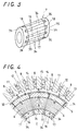
- the rotor 3 is composed of a cylindrical magnetic path 7 arranged on the rotor shaft 2 and extended axially to areas confronting the electromagnet coils 10 on the rotor shaft 2, a magnetic permeable member 6 arranged around the cylindrical magnetic path 7, and the permanent-magnet member 5 of more than one permanent-magnet piece 15 extended axially and arranged circumferentially over the outside periphery of the magnetic permeable member 6 with nonmagnetic pieces 14 being each interposed between any two adjoining permanent-magnet pieces 15. It is also to be noted that the permanent-magnet pieces 15 are arranged in such a configuration that unlike poles, or N- and S-pole, alternate in polarity circularly around the rotor 3.
- a first reinforcing member 13 to keep the permanent-magnet member 5 against falling off the rotor 3 owing to a high centrifugal force, the reinforcing member 13 being made of high tensile carbon fibers of a core material, which is impregnated with molten aluminum then, followed by solidification.
- the cylindrical magnetic path 7, as shown particularly in FIGS. 3 and 4, includes an N-pole annular portion 7N arranged confronting any one of the electromagnet coils 10, N-pole electromagnet magnetic paths 16 stemming from the N-pole annular portion 7N in opposition to N-poles of the permanent-magnet pieces 15, an S-pole annular portion 7S arranged confronting another of the electromagnet coils 10, and S-pole electromagnet magnetic paths 17 stemming from the S-pole annular portion 7S in opposition to S-poles of the permanent-magnet pieces 15.
- the N-pole electromagnet magnetic paths 16 are circumferentially interdigitated with the S-pole electromagnet magnetic paths 17 with nonmagnetic members 34 being each interposed between any two adjacent N-pole and S-pole electromagnet magnetic paths 16 and 17.
- Both the N-pole and S-pole electromagnet magnetic path portions 7N and 7S are encircled with a second reinforcing member 33 to be formed in an overall cylindrical configuration.
- nonmagnetic members 18 of a material tough to pass the magnetic force such as aluminum, copper alloys, resinous material, austenite SUS, and so on are filled in between any tip 35 of the N-pole electromagnet magnetic path 16 and the S-pole cylindrical portion 7S and also between any tip 36 of the S-pole electromagnet magnetic path 17 and the N-pole cylindrical portion 7N.
- molten resinous material of heat-resistant property is charged in any clearance between any two adjacent permanent-magnet pieces 15 and also any clearance between any adjacent N-pole and S-pole electromagnet magnetic paths 16 and 17.
- the clearance between any adjacent N-pole and S-pole electromagnet magnetic paths 16 and 17 is made larger in distance than the sum of the air gap 32 between the rotor 3 and the stator 4 and the clearance between the magnetic permeable member 6 and a magnetic path 9 to thereby keep the magnetic flux against magnetic leakage.
- the stator 4 is comprised of a toothed stator core 37 constructed of an outside cylindrical magnetic path 38 with stator teeth 11 arranged spaced circumferentially apart from each other to separate two adjacent stator slots 12, which open onto or near the air gap 32 kept between the outer periphery of the rotor 3 and the tooth tips, and windings 8 wound on stator teeth 11 with spanning some stator slots 12 so as to be substantially equal out of phase.
- magnetic paths 9 are fixed to the housing halves 1A and 1B in opposition to the axially opposing ends of the stator 4, each to each end.
- the electromagnet coils 10 are mounted to their associated magnetic paths 9 to encircle the revolving magnetic permeable member 6.
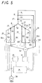
- the windings 8 are each grouped into more than one winding set 1U-1V-1W, 2U-2V-2W and 3U-3V-3W that are divided circumferentially regarding the stator slots 12 of the stator core 37 and wound shifted from each other in the stator slot 12 to form three-phase wye-connections, which are allowed to be connected in series.
- the windings 8 belonging to any one winding set have terminals that make connections 27, refer to FIG. 5, where there are provided output terminals switched over in accordance with instructions of controller unit 25, so that any desired electric power varied depending on the rpm of the rotor may be produced.
- the windings 8 are grouped into, for example three winding sets as shown in FIG.
- the controller unit 25 serves connecting the output terminals led out of the connections 27 either in series as in FIG. 5 or in parallel in FIG. 6(B) in response to an event where the engine or rotor 3 is low in rpm, thus reducing the number of the connections 17 made in series as the rpm raises, thereby to ensure the desired output voltage kept always constant irrespective of the varied rpm.
- the first and second winding sets are connected in series while only the third winding set makes another three-phase connection for the low-voltage side, as shown in FIG. 6(A).
- the controller unit 25 in response to the event where the output terminals are connected to provide the output of low voltage, makes the electromagnet coils 10 conductive in a manner flowing a current in the direction to increase the N-pole magnetic force, whereas in response to another event where the output is high in voltage, makes the electromagnets 10 conductive in a manner flowing a current in the direction to decrease the N-pole magnetic force, thereby providing the desired output voltage kept always constant.
- the controller unit 25 makes the electromagnet coils 10 conductive so as to decay the magnetic force of the permanent-magnet member 5.
- the controller unit 25 is connected to the connections 27 among the winding sets through lines 28 and relays 30A, 30B, 30C, 30D, 30E, 30F, 30G, 30H and 30I.
- the controller unit 25 turns selectively on and/or off any selected from the relays 30A to 30I, thereby connecting selectively any of the winding sets in parallel and/or in series, or remaining alone to produce a three-phase a-c source 30.
- the controller unit 25 depending on the rpm of the rotor 3, makes not only conduction control to the electromagnet coils 10 but also on-off control of the switching relays to connect the winding sets in parallel and/or in series, thereby yielding the three-phase a-c source 30 of a desired a-c voltage.
- the controller unit 25 includes a rectifier 31 where the produced power of the desired voltage is rectified to a d-c of, for example 24V, and an inverter 29, yielding a three-phase a-c of 50 ⁇ 60Hz at 200V
- the controller unit 25 controls the on-off operation of the relays, depending on the rpm of the rotor 3, thereby realizing the output voltage (V) of fixed level as shown in FIG. 7(A).
- a low-voltage, large-current generator may be provided in which the windings 8 on the stator 4 are constructed in phase in matching with the number of pole of the permanent magnet on the rotor 3 and the winding sets 1U-1V-1W, 2U-2V-2W and 3U-3V-3W are connected in parallel.
Landscapes
- Engineering & Computer Science (AREA)
- Power Engineering (AREA)
- Chemical & Material Sciences (AREA)
- Combustion & Propulsion (AREA)
- Transportation (AREA)
- Mechanical Engineering (AREA)
- Permanent Magnet Type Synchronous Machine (AREA)
- Control Of Eletrric Generators (AREA)
- Iron Core Of Rotating Electric Machines (AREA)
- Permanent Field Magnets Of Synchronous Machinery (AREA)
Abstract
Description
Claims (12)
- A motor-generator with a voltage stabilizer, comprising a multipolar permanent-magnet rotor(3) mounted on a rotor shaft(2) supported for rotation in a stator housing(1), a stator(4) fixed to the housing(1) with arranged around the rotor(3), and electromagnet coils(10) fixed to axially opposing ends of the housing (1), each to each end, in opposition to axially opposing ends of the rotor(3), wherein the rotor(3) is composed of a cylindrical magnetic path(7) arranged around the rotor shaft(2) and extended axially to areas confronting the electromagnet coils(10), a permeable member(6) surrounding around the cylindrical magnetic path(7), and a permanent-magnet member(5) of more than one permanent-magnet piece(15) extended axially and arranged circumferentially around an outside periphery of the permeable member(6) with N- and S-poles on either piece alternating in polarity circularly around the rotor(3), and wherein the cylindrical magnetic path (7) includes an N-pole annular portion(7N) arranged confronting any one of the electromagnet coils(10), N-pole electromagnet magnetic paths(16) stemming from the N-pole annular portion(7N) in opposition to the N-poles of the permanent-magnet pieces(15), an S-pole annular portion(7S) arranged confronting another of the electromagnet coils(10), and S-pole electromagnet magnetic paths(17) stemming from the S-pole annular portion(7S) in opposition to the S-poles of the permanent-magnet pieces(15), the N-pole and S-pole electromagnet magnetic paths(16,17) alternating in polarity circularly around the permanent-magnet member (5) with nonmagnetic pieces(14) being each interposed between any two adjacent electromagnet magnetic paths (16,17).
- A motor-generator constructed as defined in claim 1, wherein around the outside periphery of the permanent-magnet member(5) there is provided a first reinforcing member(13) to keep the permanent-magnet member(5) against falling off the rotor(3) owing to a high centrifugal force, the reinforcing member(13) being made of high tensile carbon fibers of a core material, which is impregnated with molten aluminum then, followed by solidification.
- A motor-generator constructed as defined in claims 1 or 2, wherein both the N-pole and S-pole electromagnet magnetic paths(16,17) are encircled with a second reinforcing member(33) to be formed in an overall cylindrical configuration.
- A motor-generator constructed as defined in any one of claims 1 ~ 3, wherein nonmagnetic members (18) of a material tough to pass the magnetic force, such as aluminum, copper alloys, resinous material, austenite steel, and so on are filled in between any tip(35) of the N-pole electromagnet magnetic path(16) and the S-pole cylindrical portion(7S) and also between any tip(36) of the S-pole electromagnet magnetic path (17) and the N-pole cylindrical portion(7N), and a clearance between any adjacent N-pole and S-pole electromagnet magnetic paths(16,17) is made larger in distance than a sum of an air gap between the rotor(3) and the stator(4) and a clearance between the magnetic permeable member(6) and the rotor(3).
- A motor-generator constructed as defined in any one of claims 1 ~ 4, wherein molten aluminum or resinous material of heat-resistant property is charged in any clearance between any two adjacent permanent-magnet pieces(15) and also any clearance between any adjacent N-pole and S-pole electromagnet magnetic paths (16,17).
- A motor-generator constructed as defined in any one of claims 1 ~ 5, wherein the stator(4) is comprised of a stator core(37) with stator teeth(11) arranged spaced circumferentially apart from each other to separate two adjacent stator slots(12), and windings (8) wound on stator teeth(11) with spanning some stator slots(12) so as to be substantially equal out of phase, and wherein the windings(8) are each grouped into more than one winding set(1U-1V-1W, 2U-2V-2W, 3U-3V-3W) shifted from each other to form three-phase wye-connections, which are allowed to be connected either in series or in parallel, so that a controller(25) selectively changes over among output terminals led out of the connections(27) every winding set(1U-1V-1W, 2U-2V-2W, 3U-3V-3W), thus producing a desired output power in accordance with a rpm of the rotor(3).
- A motor-generator constructed as defined in claim 6, wherein the stator(4) windings(8) are grouped into low-voltage winding sets and high-voltage winding sets, and the controller(25) regulates magnetic flux to produce two types of power, which are different in rated voltage.
- A motor-generator constructed as defined in claim 7, wherein the low-voltage winding sets and the high-voltage winding sets are connected in parallel to give a generation characteristic of low-voltage, large-current.
- A motor-generator constructed as defined in any one of claims 6 ~ 8, wherein the controller(25) serves connecting in series the output terminals led out of the connections(27) in response to an event where the engine or rotor(3) is low in rpm, and reducing the number of the connections made in series as the rpm raises, thereby to ensure the desired output voltage kept always constant irrespective of variation in the rpm.
- A motor-generator constructed as defined in any one of claims 6 ~ 9, wherein with the rotor(3) being operated in a preselected rpm range, the controller(25) in response to the event where the output terminals are connected to provide the output of low voltage, makes the electromagnet coils(10) conductive in a direction to increase the N-pole magnetic force, whereas in response to another event where the output is high in voltage, makes the electromagnets conductive in a reverse direction to decrease the N-pole magnetic force, thereby providing the desired output voltage kept always constant.
- A motor-generator constructed as defined in any one of claims 6 ~ 10, wherein the controller(25) includes a rectifier(31) where a produced power of the desired voltage is rectified to a d-c, and an inverter (29) yielding an a-c of a desired frequency.
- A motor-generator constructed as defined in any one of claims 6 ~ 11, wherein the controller(25) makes the electromagnet coils(10) conductive in a manner to reduce the magnetic force of the permanent-magnet member(5) when the motor-generator is used as a motor.
Applications Claiming Priority (2)
| Application Number | Priority Date | Filing Date | Title |
|---|---|---|---|
| JP2001043103 | 2001-02-20 | ||
| JP2001043103A JP3709145B2 (en) | 2001-02-20 | 2001-02-20 | Voltage stabilizer for permanent magnet generator / motor |
Publications (3)
| Publication Number | Publication Date |
|---|---|
| EP1233498A2 true EP1233498A2 (en) | 2002-08-21 |
| EP1233498A3 EP1233498A3 (en) | 2004-03-31 |
| EP1233498B1 EP1233498B1 (en) | 2006-03-22 |
Family
ID=18905326
Family Applications (1)
| Application Number | Title | Priority Date | Filing Date |
|---|---|---|---|
| EP20010306373 Expired - Lifetime EP1233498B1 (en) | 2001-02-20 | 2001-07-25 | Permanent-Magnet motor-generator with voltage stabilizer |
Country Status (3)
| Country | Link |
|---|---|
| EP (1) | EP1233498B1 (en) |
| JP (1) | JP3709145B2 (en) |
| DE (1) | DE60118124T8 (en) |
Cited By (9)
| Publication number | Priority date | Publication date | Assignee | Title |
|---|---|---|---|---|
| WO2009026767A1 (en) * | 2007-08-31 | 2009-03-05 | Leiting Zhang | A hybrid excitation synchronous generator with inner and outer voltage regulation systems and its voltage regulation method |
| EP1746716A3 (en) * | 2005-07-20 | 2009-06-17 | Hamilton Sundstrand Corporation | Buck/boost method of voltage regulation for a permanent magnet generator (PMG) |
| CN101291098B (en) * | 2008-05-05 | 2011-06-29 | 哈尔滨工业大学 | Mixed excitation compensating pulse generator |
| CN102868274A (en) * | 2011-07-06 | 2013-01-09 | 精工爱普生株式会社 | Electromechanical device, robot, and mobile unit |
| RU2583837C1 (en) * | 2015-01-12 | 2016-05-10 | Федеральное государственное бюджетное образовательное учреждение высшего профессионального образования "Уфимский государственный авиационный технический университет" | Integrated high-temperature starter-generator and control method thereof |
| EP2820743A4 (en) * | 2012-02-27 | 2016-10-19 | Lit Motors Corp | VEHICLE ENGINE ASSEMBLIES |
| CN106787572A (en) * | 2016-12-24 | 2017-05-31 | 大连碧蓝节能环保科技有限公司 | Segmentation phase shift starts pole-changing windingses permasyn morot |
| CN109038943A (en) * | 2016-05-11 | 2018-12-18 | 韦雪 | A kind of integrated dual-purpose machine device of motor generator |
| CN109712510A (en) * | 2019-01-17 | 2019-05-03 | 上海大学 | A kind of small-power magneto is to dragging teaching experiment platform |
Families Citing this family (9)
| Publication number | Priority date | Publication date | Assignee | Title |
|---|---|---|---|---|
| CN100385778C (en) * | 2003-12-11 | 2008-04-30 | 泰豪科技股份有限公司 | Mictomagnetism dual voltage medium frequency brushless synchronous generator |
| JP4840156B2 (en) * | 2007-01-24 | 2011-12-21 | 三菱自動車工業株式会社 | Permanent magnet generator |
| JP4946694B2 (en) * | 2007-07-27 | 2012-06-06 | 三菱自動車工業株式会社 | Control device for permanent magnet generator |
| JP5722690B2 (en) | 2011-04-19 | 2015-05-27 | T.K Leverage株式会社 | Power generator |
| CN103326528A (en) * | 2013-07-02 | 2013-09-25 | 金王迅 | Electromagnetic compatibility (EMC) triple-insulated anti-interference high-voltage permanent magnet brushless electric tool |
| CN104134382A (en) * | 2014-03-29 | 2014-11-05 | 高忠青 | Electromagnetic experiment operation platform |
| RU2637767C2 (en) * | 2016-03-16 | 2017-12-07 | Федеральное государственное бюджетное образовательное учреждение высшего профессионального образования "Уфимский государственный авиационный технический университет" | Method of stabilization of output voltage of magnetoelectric generator |
| JP6741617B2 (en) * | 2017-03-29 | 2020-08-19 | 日野自動車株式会社 | Power generator |
| CN109149821B (en) | 2018-11-07 | 2024-12-20 | 珠海格力电器股份有限公司 | Motor rotors and permanent magnet motors |
Family Cites Families (3)
| Publication number | Priority date | Publication date | Assignee | Title |
|---|---|---|---|---|
| EP1037365A1 (en) * | 1999-03-12 | 2000-09-20 | Isuzu Ceramics Research Institute Co., Ltd. | Motor generator developing high torque |
| FR2791485B1 (en) * | 1999-03-26 | 2003-05-02 | Valeo Equip Electr Moteur | ROTATING MACHINE COMPRISING IMPROVED EXCITATION MEANS |
| JP2001095212A (en) * | 1999-07-19 | 2001-04-06 | Mitsuba Corp | Dynamo-electric machine |
-
2001
- 2001-02-20 JP JP2001043103A patent/JP3709145B2/en not_active Expired - Fee Related
- 2001-07-25 DE DE2001618124 patent/DE60118124T8/en not_active Expired - Fee Related
- 2001-07-25 EP EP20010306373 patent/EP1233498B1/en not_active Expired - Lifetime
Cited By (12)
| Publication number | Priority date | Publication date | Assignee | Title |
|---|---|---|---|---|
| EP1746716A3 (en) * | 2005-07-20 | 2009-06-17 | Hamilton Sundstrand Corporation | Buck/boost method of voltage regulation for a permanent magnet generator (PMG) |
| CN101807876A (en) * | 2005-07-20 | 2010-08-18 | 哈米尔顿森德斯特兰德公司 | The buck/boost method that is used for the voltage-regulation of permanent magnet generator |
| WO2009026767A1 (en) * | 2007-08-31 | 2009-03-05 | Leiting Zhang | A hybrid excitation synchronous generator with inner and outer voltage regulation systems and its voltage regulation method |
| CN101291098B (en) * | 2008-05-05 | 2011-06-29 | 哈尔滨工业大学 | Mixed excitation compensating pulse generator |
| CN102868274A (en) * | 2011-07-06 | 2013-01-09 | 精工爱普生株式会社 | Electromechanical device, robot, and mobile unit |
| EP2820743A4 (en) * | 2012-02-27 | 2016-10-19 | Lit Motors Corp | VEHICLE ENGINE ASSEMBLIES |
| RU2583837C1 (en) * | 2015-01-12 | 2016-05-10 | Федеральное государственное бюджетное образовательное учреждение высшего профессионального образования "Уфимский государственный авиационный технический университет" | Integrated high-temperature starter-generator and control method thereof |
| CN109038943A (en) * | 2016-05-11 | 2018-12-18 | 韦雪 | A kind of integrated dual-purpose machine device of motor generator |
| CN109038943B (en) * | 2016-05-11 | 2020-12-25 | 重庆翔工工贸有限公司 | Motor and generator integrated dual-purpose machine device |
| CN106787572A (en) * | 2016-12-24 | 2017-05-31 | 大连碧蓝节能环保科技有限公司 | Segmentation phase shift starts pole-changing windingses permasyn morot |
| CN106787572B (en) * | 2016-12-24 | 2018-11-16 | 大连碧蓝节能环保科技有限公司 | It is segmented phase shift and starts pole-changing windings permasyn morot |
| CN109712510A (en) * | 2019-01-17 | 2019-05-03 | 上海大学 | A kind of small-power magneto is to dragging teaching experiment platform |
Also Published As
| Publication number | Publication date |
|---|---|
| DE60118124T2 (en) | 2006-08-31 |
| EP1233498B1 (en) | 2006-03-22 |
| DE60118124T8 (en) | 2007-04-19 |
| JP2002247819A (en) | 2002-08-30 |
| JP3709145B2 (en) | 2005-10-19 |
| EP1233498A3 (en) | 2004-03-31 |
| DE60118124D1 (en) | 2006-05-11 |
Similar Documents
| Publication | Publication Date | Title |
|---|---|---|
| US6541887B2 (en) | Permanent-magnet motor-generator with voltage stabilizer | |
| EP1233498B1 (en) | Permanent-Magnet motor-generator with voltage stabilizer | |
| US6703747B2 (en) | Generator with diverse power-generation characteristics | |
| US4980595A (en) | Multiple magnetic paths machine | |
| US9979266B2 (en) | Electrical rotating machines | |
| US7134180B2 (en) | Method for providing slip energy control in permanent magnet electrical machines | |
| US6097124A (en) | Hybrid permanent magnet/homopolar generator and motor | |
| US9935532B2 (en) | Double-rotor type electrical rotating machines | |
| CN101438483B (en) | Compact high power alternator | |
| EP0789441B1 (en) | Electrical generating system for a motor vehicle | |
| US5444321A (en) | Induction alternating current generator and a generation method | |
| MXPA05001704A (en) | Double-excitation rotating electrical machine for adjustable defluxing. | |
| JP2011507483A (en) | Electromechanical transducer operating method, controller, and computer program | |
| EP1035635A2 (en) | Motor generator developing low torque at high-speed revolutions without cogging | |
| KR20180081672A (en) | Mechanical drive to the motor and alternator | |
| MXPA96006245A (en) | Generator system of electric power for a vehicle of mo | |
| EP1037365A1 (en) | Motor generator developing high torque | |
| KR20190090755A (en) | Mechanical drive to the motor and alternator | |
| JP2003164125A (en) | Double-sided gap type rotary electric machine | |
| JP3676262B2 (en) | Generator with multiple power generation characteristics | |
| US20060113861A1 (en) | Motor vehicle AC generator having a rotor incorporating a field winding and permanent magnets | |
| RU2273942C1 (en) | Synchronous generator with excitation by permanent magnets | |
| JP4346955B2 (en) | Rotating electric machine | |
| EP0275251B1 (en) | Alternator assembly | |
| US20080067883A1 (en) | Generator and/or motor assembly |
Legal Events
| Date | Code | Title | Description |
|---|---|---|---|
| PUAI | Public reference made under article 153(3) epc to a published international application that has entered the european phase |
Free format text: ORIGINAL CODE: 0009012 |
|
| AK | Designated contracting states |
Kind code of ref document: A2 Designated state(s): AT BE CH CY DE DK ES FI FR GB GR IE IT LI LU MC NL PT SE TR |
|
| AX | Request for extension of the european patent |
Free format text: AL;LT;LV;MK;RO;SI |
|
| PUAL | Search report despatched |
Free format text: ORIGINAL CODE: 0009013 |
|
| AK | Designated contracting states |
Kind code of ref document: A3 Designated state(s): AT BE CH CY DE DK ES FI FR GB GR IE IT LI LU MC NL PT SE TR |
|
| AX | Request for extension of the european patent |
Extension state: AL LT LV MK RO SI |
|
| 17P | Request for examination filed |
Effective date: 20040910 |
|
| AKX | Designation fees paid |
Designated state(s): DE FR GB IT |
|
| 17Q | First examination report despatched |
Effective date: 20041214 |
|
| GRAP | Despatch of communication of intention to grant a patent |
Free format text: ORIGINAL CODE: EPIDOSNIGR1 |
|
| GRAS | Grant fee paid |
Free format text: ORIGINAL CODE: EPIDOSNIGR3 |
|
| GRAA | (expected) grant |
Free format text: ORIGINAL CODE: 0009210 |
|
| AK | Designated contracting states |
Kind code of ref document: B1 Designated state(s): DE FR GB IT |
|
| REG | Reference to a national code |
Ref country code: GB Ref legal event code: FG4D |
|
| REF | Corresponds to: |
Ref document number: 60118124 Country of ref document: DE Date of ref document: 20060511 Kind code of ref document: P |
|
| PGFP | Annual fee paid to national office [announced via postgrant information from national office to epo] |
Ref country code: FR Payment date: 20060712 Year of fee payment: 6 |
|
| PGFP | Annual fee paid to national office [announced via postgrant information from national office to epo] |
Ref country code: IT Payment date: 20060731 Year of fee payment: 6 |
|
| ET | Fr: translation filed | ||
| PLBE | No opposition filed within time limit |
Free format text: ORIGINAL CODE: 0009261 |
|
| STAA | Information on the status of an ep patent application or granted ep patent |
Free format text: STATUS: NO OPPOSITION FILED WITHIN TIME LIMIT |
|
| 26N | No opposition filed |
Effective date: 20061227 |
|
| REG | Reference to a national code |
Ref country code: FR Ref legal event code: ST Effective date: 20080331 |
|
| PG25 | Lapsed in a contracting state [announced via postgrant information from national office to epo] |
Ref country code: FR Free format text: LAPSE BECAUSE OF NON-PAYMENT OF DUE FEES Effective date: 20070731 |
|
| PG25 | Lapsed in a contracting state [announced via postgrant information from national office to epo] |
Ref country code: IT Free format text: LAPSE BECAUSE OF NON-PAYMENT OF DUE FEES Effective date: 20070725 |
|
| PGFP | Annual fee paid to national office [announced via postgrant information from national office to epo] |
Ref country code: DE Payment date: 20090731 Year of fee payment: 9 |
|
| PGFP | Annual fee paid to national office [announced via postgrant information from national office to epo] |
Ref country code: GB Payment date: 20100726 Year of fee payment: 10 |
|
| PG25 | Lapsed in a contracting state [announced via postgrant information from national office to epo] |
Ref country code: DE Free format text: LAPSE BECAUSE OF NON-PAYMENT OF DUE FEES Effective date: 20110201 |
|
| REG | Reference to a national code |
Ref country code: DE Ref legal event code: R119 Ref document number: 60118124 Country of ref document: DE Effective date: 20110201 |
|
| GBPC | Gb: european patent ceased through non-payment of renewal fee |
Effective date: 20110725 |
|
| PG25 | Lapsed in a contracting state [announced via postgrant information from national office to epo] |
Ref country code: GB Free format text: LAPSE BECAUSE OF NON-PAYMENT OF DUE FEES Effective date: 20110725 |