BACKGROUND OF THE INVENTION
The present invention relates to an optical communication
system and particularly to a collimator-pair optical device which
is used in combination with optical fibers.
The demand for increasing the capacity of an optical fiber
communication network has been intensified with the rapid and
wide spread of the Internet in recent years. The development
of WDM (wavelength division multiplexing) communication as means
for increasing the network capacity has been promoted rapidly.
In WDM communication, individual pieces of information are
transmitted by light components slightly different in wavelength.
It is therefore necessary to use an optical functional device
good in wavelength selection characteristic such as an optical
demultiplexer, an optical filter, an optical isolator or an optical
circulator. It is a matter of course that the functional device
is intensively demanded in terms of manufacturability, reduction
in size, integration, and stability.
In most cases, the optical functional device is configured
as follows. Light emitted from an end surface of an emission
side optical fiber is converted into parallel luminous flux by
a collimator. The parallel luminous flux is transmitted through
a planar optical functional device having a function of a filter
or isolator. Then, the parallel luminous flux is condensed by
a condenser lens again, so that the condensed luminous flux is
sent to an end surface of an incidence side optical fiber. A
rod lens having a radially refractive index distribution, a
spherical glass lens, or an aspherical molding lens, is used
as each of the collimator and the condenser lens . The lens easiest
to handle from the point of view of shape and aberration correction
is a gradient index rod lens.
Fig. 1 is a schematic view showing an example of a collimator
parallel pair using first and second plano-convex lenses 3 and
4 each made of a homogeneous material. Generally, in the parallel
pair, two lenses equivalent to each other (lens thickness: Z)
are disposed on opposite sides so as to be separated at a distance
2L from each other. In the case of lenses asymmetric in shapes
of lens surfaces as shown in Fig. 1, the two lenses 3 and 4 are
disposed in directions reverse to each other. That is, in the
case shown in Fig. 1, the first lens 3 has a planar surface 30
as an incident surface, and a curved surface 130 as an exit surface.
On the contrary, the second lens 4 has a curved surface 140
as an incident surface, and a planar-surface 40 as an exit surface.
The curved surfaces 130 and 140 may be spherical surfaces or
may be aspherical surfaces. Optical fibers equal in mode field
diameter to each other and having the same characteristic are
used as an incidence side optical fiber 1 (hereinafter referred
to as "light source fiber") and an exit side optical fiber 2
(hereinafter referred to as "light-receiving fiber"). The
distance WD between an end surface 10 of the light source fiber
1 and the incident surface 30 of the lens 3 and the distance
WD between the exit surface 40 of the lens 4 and an end surface
20 of the light-receiving fiber 2 are made equal to each other
to thereby form a completely symmetric optical system.
Fig. 1 is a geometrically optical typical view in which
light rays 5 are expressed. Luminous flux really emitted from
a single-mode optical fiber, however, can be regarded as a Gaussian
beam as shown in Fig. 2. In this case, two lenses 3 and 4 need
be disposed so that a beam waist (BW) 26 of a Gaussian beam 7
is formed at a midpoint between the two lenses 3 and 4 in order
to obtain good coupling efficiency of the collimator parallel
pair. That is, a first beam waist 16 (with a radius of w1)
corresponding to light 17 emitted from the light source fiber
1 once forms a second beam waist 16 (with a radius of w2) at
the midpoint of the optical system and is coupled to the
light-receiving fiber 2 in the position of a third beam waist
36 (with a radius of w3 equal to w1) by the second lens 4.
If the wavelength used, the NA (numerical aperture) of each
optical fiber and the positions of the focal point and principal
point of each lens are known, the values of WD and L in the
configuration of Fig. 2 can be designed by calculation based
on so-called ABCD rules using elements of a light ray matrix.
Theoretically, for example, detailed numerical formulae have
been described in Foundation and Application of Optical Coupling
System for Optical Device Gendai Kougaku Sha (1991) written by
Kenji Kawano. Some of optical design software programs available
on the market have such ABCD calculating functions.
However, the inter-lens distance, that is, the distance
L between the lens 3 or 4 and the second BW 26 is not allowed
to be selected to be larger than the maximum value Lmax because
of the presence of the maximum value Lmax. The relation between
WD and L in a lens with a focal length f is typically shown in
Fig. 3.
In such an optical coupling system, the ratio of the power
of light incident on the light-receiving fiber to the power of
light emitted from the light source fiber, that is, coupling
efficiency or coupling loss is an important characteristic
parameter. If L is not larger than Lmax, coupling efficiency
of 100 % (coupling loss of 0 dB) can be obtained theoretically
when the value of WD is selected suitably. On the contrary,
if L exceeds Lmax, coupling loss increases rapidly (Fig. 4).
Incidentally, the value of Lmax increases substantially in
proportional to the square of the focal length of the lens.
Although a completely symmetric optical system has been
described above as an example, the optical coupling system may
be configured so that the light source is constituted not by
an optical fiber but by a light-emitting device such as a
semiconductor laser while the light-receiving unit is constituted
not by an optical fiber but by a photo detector such as a photodiode.
Also in this case, the system can be designed on the basis of
application of a Gaussian beam as described above.
Results of the ABCD calculation are, however, only based
on paraxial data. The ABCD calculation can hold upon the premise
that each lens has no aberration and that there is no shading
caused by the influence of shortage of the effective diameter
of the lens. In a lens practically used in such an optical system,
loss caused by various kinds of aberration residual in the lens
is inevitably produced. For this reason, the inter-lens distance
2L and the coupling loss do not always have such a simple relation
as shown in Fig. 4. It is further considered that the coupling
loss changes when the condition of the focal length and aberration
of the lens changes in accordance with the change of temperature
and humidity. In addition, the change in volume and length of
a component for holding the lens or optical fiber is one of causes
of the coupling loss.
SUMMARY OF THE INVENTION
The invention is devised to solve the problem and an object
of the invention is provide a configuration condition in which
coupling loss is minimized in an optical coupling system under
the presence of a certain degree of aberration, defect, and
environmental change.
According to the invention, there is provided an optical
coupling system including: a first lens having an incident surface
disposed in a certain direction and having a positive refractive
power, by the first lens, Gaussianbeam-like luminous flux incident
on the incident surface from a light source being converted into
approximately parallel luminous flux; and a second lens having
the same refractive power as that of the first lens but having
an incident surface and an exit surface disposed in a reverse
direction, by the second lens, the approximately parallel luminous
flux incident on the incident surface of the second lens being
converted into converged luminous flux, the converged luminous
flux being incident on a light-receiving unit; wherein a distance
between the two lenses is selected to be approximately equal
to a maximum distance allowing beam waists to be formed at equal
distances from the two lenses respectively.
That is, when the distance between the two lenses is assumed
to be 2L and the maximum distance allowing beam waists to be
formed at equal distances from the two lenses respectively is
assumed to be 2Lmax, the distance 2L is preferably in a range
given by the expression 1.8Lmax ≤ 2L ≤ 2Lmax.
Further, in the optical coupling system according to the
invention, total coupling loss is set to be equal to or smaller
than coupling loss which occurs when the distance 2L between
the two lenses is in a range given by the expression 0 ≤ 2L <
1.8Lmax. The value of total coupling loss is desirably not larger
than 0.05 dB.
The optical coupling system according to the invention
includes: a lens having a positive refractive power, by the lens,
Gaussian beam-like luminous flux emitted from a light source
being converted into approximately parallel luminous flux; and
a reflection surface disposed at the rear of the lens so that
the approximately parallel luminous flux is reflected by the
reflection surface to return to the lens, the returning luminous
flux being converted, by the lens, into converged luminous flux
which is incident on a light-receiving unit disposed in the light
source and its vicinity; wherein a distance between the lens
and the reflection surface is selected to be approximately equal
to the maximum distance allowing the lens to form a beam waist.
That is, when the distance between the lens and the reflection
surface is assumed to be L and the maximum distance allowing
the lens to form a beam waist is assumed to be Lmax, the distance
L is preferably selected to be in a range given by the expression
0.9Lmax ≤ L ≤ Lmax.
Further, in the optical coupling system according to the
invention, total coupling loss is set to be equal to or smaller
than coupling loss which occurs when the distance L between the
lens and the refection surface is in a range given by the expression
0 ≤ L < 0.9Lmax. The value of total coupling loss is desirably
not larger than 0.05 dB.
The light source and the light-receiving unit are constituted
by end surfaces of optical fibers which are equal in mode field
diameter to each other. Incidentally, in the case of the optical
coupling system according to the invention, an end surface of
an optical fiber can be used so as to serve as the light source
and also as the light-receiving unit.
Arod lens having a gradient index distribution in a direction
of the radius thereof, a plano-convex lens having a gradient
index distribution in a direction of the optical axis thereof,
a plano-convex lens made of a homogeneous material, a sphere
lens made of a homogeneous material, or a grating lens surface
may be used as the lens having a positive refractive power.
An optical device is constituted by the optical coupling
system according to the invention, and an optical functional
device disposed at a midpoint between the two lenses in the optical
coupling system. In the optical coupling system according to
the invention, an optical functional device may be disposed at
a midpoint between the lens and the reflection surface so that
an optical device can be formed. In the optical device, the
optical coupling system may be provided as an array in which
optical coupling systems having the same function are arranged
in one row or in a plurality of rows.
In the optical coupling system which is set according to
the invention so that the distance between the lenses or the
distance between the lens and the reflection surface corresponds
to the maximum distance allowing each lens to form a beam waist,
coupling loss little changes even in the case where a certain
degree of increase in aberration or defects occurs against an
ideal optical system or even in the case where the performance
of the optical system varies in accordance with the environmental
change. In addition, the performance of the optical device
obtained by applying the optical coupling system according to
the invention little changes against the displacement from the
ideal design condition or against the environmental change.
The present disclosure relates to the subject matter contained
in Japanese patent application No. 2001-038412 (filed on February
15, 2001), which is expressly incorporated herein by reference
in its entirety.
BRIEF DESCRIPTION OF THE DRAMINGS
Fig. 1 is an explanatory view geometrically showing coupling
of optical fibers by a collimator parallel pair.
Fig. 2 is an explanatory view showing coupling of optical
fibers by a collimator parallel pair in terms of typical Gaussian
beams.
Fig. 3 is a graph typically showing the relation between
the distance WD of each lens from a corresponding optical fiber
and the distance (half value) L between the two lenses.
Fig. 4 is a graph typically showing the relation between
the distance (half value) L between two ideal lenses and coupling
loss.
Fig. 5 is a graph typically showing the relation between
WD and L in the case where the focal length f of each lens varies.
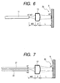
Fig. 6 is a view for explaining a configuration in which
a lens, an optical fiber and a reflection surface are used.
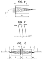
Fig. 7 is a view for explaining a configuration in which
a lens, two optical fibers and a reflection surface are used.
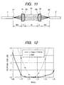
Fig. 8 is a view showing the optical path of a grating lens.
Fig. 9 is a view showing longitudinal spherical aberration
of a grating lens.
Fig. 10 is a view showing a configuration of an optical
coupling system according to a first design sample.
Fig. 11 is a view showing a configuration of an optical
coupling system according to a second design sample.
Fig. 12 is a graph showing results of calculation of coupling
loss in the second design sample.
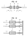
Fig. 13 is a view showing a configuration of an optical
coupling system according to a third design sample.
Fig. 14 is a graph showing results of calculation of coupling
loss in the third design sample.
Fig. 15 is a view showing an optical device using the optical
coupling system according to the second design sample.
Fig. 16 is a view showing a configuration of an optical
device using a plurality of optical coupling systems according
to the third design sample.
DESCRIPTION OF THE PREFERRED EMBODIMENT
Fig. 5 is a graph in which the relation in a lens with a
focal length of (f + Δf) slightly larger than f overlaps the
relation in the graph shown in Fig. 3. When, for example, WD
is equal to WD1, the difference (ΔL) between the L values of
the two lenses expresses the difference between the second BW
positions based on the difference between the focal lengths of
the two lenses.
Incidentally, in Fig. 5, it is found that when WD is set
so that the L value approaches Lmax, the value of ΔL becomes
very small. This means that when the L value approaches Lmax,
the second and third BW positions little change in spite of the
change of the focal length.
According to results (an example of design which will be
described later) of calculation of the relation between the BW
position and the coupling loss in a real parallel pair optical
system, it is found that increase in coupling loss due to the
change of the focal length becomes very small when there are
satisfied the following two conditions:
The following points need be considered with respect to
causes of the change of the BW position bringing increase in
coupling loss.
In accordance with these factors, the "configuration to
make the distance between the lenses coincident with Lmax" of
the invention is effective in specific cases listed as follows.
[1] Case of Use of Lens Large in Axial Chromatic Aberration
In the case of a pair of lenses used in WDM (wavelength
division multiplexing), coupling loss increases at a wavelength
far from a design reference wavelength when axial chromatic
aberration is large. In the configuration of the invention,
however, the influence of axial chromatic aberration can be
suppressed to be small. Examples of the lens large in chromatic
aberration include a kinoform-shaped grating lens, a single glass
lens with a large focal length, and a plastic lens. Especially,
the grating lens has remarkably large axial chromatic aberration
(tens of times as large as that of a convex glass lens), so that
the configuration of the invention is particularly effective.
[2] Case of Lens largely changing in Accordance with Environment
(such as Temperature and Humidity)
A plastic aspherical lens is inexpensive because it can
be mass-produced by pressing. The plastic aspherical lens,
however, has a problem that the change of the focal length or
aberration of the lens in accordance with temperature or humidity
is very large compared with that of a glass lens. According
to the configuration of the invention, however, the change of
coupling loss due to this cause can be suppressed to be small.
[3] Case of Suppressing Environmental Change to be Particularly
Small
In most cases, suppression (athermancy) of the change of
characteristic due to temperature is severely required of the
whole of a communication optical system as well as lenses in
the system. As methods for improving athermancy, there are used
a method of keeping the whole of the system at a constant temperature,
a method using a material little in its temperature change, and
a method using materials in combination to cancel their temperature
changes. When the configuration of the invention is provided
in addition to these methods, there is an effect in reducing
the change of coupling loss caused by the change of the optical
path length.
[4] Case of Rod Lens with Distortion
In a rod lens having a gradient index distribution in a
direction of the optical axis thereof, the thermal expansion
coefficient of the material of the lens changes in accordance
with a distance from the optical axis. Hence, in most cases,
radial distortion remains. Particularly in a lens with a long
focal length, the quantity of distortion becomes large. In a
lens with distortion, the focal length of the lens varies in
accordance with the direction of polarization of incident light
because of a phenomenon of birefringence. Hence, focusing is
so insufficient that coupling loss becomes large. According
to the configuration of the invention, however, sharp focusing
can be performed to reduce coupling loss because the position
of BW is trued up even in the case where the focal length varies.
As shown in Fig. 6, a reflecting mirror 8 may be set in
a position corresponding to the position of the second beam waist
26 at the midpoint between the lenses shown in Fig. 2 so that
light is returned to an optical fiber 11 which serves as a light
source fiber and also as a light-receiving fiber. Also in this
configuration, the effect of the invention can be fulfilled.
In the case shown in Fig. 6, the condition (2) of the conditions
is always satisfied:
Accordingly, when the distance between the lens 13 and the
reflecting mirror 8 is set to be near Lmax, there is an effect
in suppressing increase of coupling loss caused by defects even
in the case where the lens used has more or less the defects
as follows:
Aberration based on optic-axial asymmetry (astigmatism
generated on the optical axis); Variation of the focal length from a standard value; and Variation of the lens thickness from a standard value.
Incidentally, as shown in Fig. 7, a light source fiber 21
and a light-receiving fiber 22 in the proximity of the light
source fiber 21 are provided separately. Also in the configuration
shown in Fig. 7, the same effect as in the configuration shown
in Fig. 6 can be obtained.
A specific lens system will be described below on the basis
of results of calculation of the relation between the quantity
of astigmatism and coupling loss. The calculation was made by
use of lens design software "OSLO Six" made by Sinclair Optics,
Inc., in the U.S.
[Design Sample 1]
A collimator parallel pair constituted by grating lenses
was designed and coupling loss was calculated.
(Designed Values of Grating Lens)
Fig. 8 shows the configuration of each single lens. A grating
lens (kinoform shape) 25 with a focal length of 1 mm and an NA
of 0.2 was set on a surface of quartz glass 9 with a thickness
Zg of 1 mm. The designed wavelength λ was 1550 nm. A focal point
due to primary light was used.
A wave surface due to a plane of diffraction was shaped
like a parabola with respect to a distance
r from an optical
axis 50.
Incidentally, spherical aberration can be ignored, so that
correction due to high-order terms was not required.
(Axial Chromatic Aberration)
Fig. 9 shows longitudinal aberration of an afocal single
lens in three wavelengths (1520, 1550 and 1580 nm). It is found
that the focal position moves by about 20 µm with respect to
Δλ = 30 nm because the axial chromatic aberration is very large.
This is a problem on such a grating lens.
(Coupling Efficiency of Collimator Parallel Pair)
As shown in Fig. 10, grating lenses 23 and 24 formed on
surfaces of two pieces of quartz glass 19 and 29 respectively
were disposed, in the same manner as described above, as a parallel
pair symmetrically between a light source fiber 1 and a
light-receiving fiber 2 having a mode field diameter equal to
that of the light source fiber 1. Coupling loss was calculated
by the following procedure. For calculation, the diameter and
position of BW (on the basis of ABCD calculation) were considered
but loss due to surface reflection, internal absorption,
diffraction efficiency and spherical aberration was ignored.
The light source fiber 1 and the light-receiving fiber 2 were
both provided to have an NA of 0.1 (1/e
2 strength) at a wavelength
λ = 1550 nm.
(a) Case of Short L
Table 1 shows results of calculation in the case of L =
0.0836 nm and WD = 0.3053 nm.
Coupling loss at λ = 1550 nm was small. The position of
BW, however, moved largely on the receiving side when λ changed.
Hence, large loss of from 0.5 to 0.8 dB was produced in the
Δλ range of ±30 nm.
| Wavelength (nm) | Light Source BW Radius w1 (µm) | Light-Rece iving Side BW Position (µm) | Light-Rece iving Side BW radius w3 (µm) | Coupling Loss (dB) |
| 1550 | 4.909 | 0 | 4.909 | 0.004 |
| 1520 | 4.814 | 40.48 | 4.993 | 0.753 |
| 1580 | 5.004 | -37.59 | 4.831 | 0.551 |
In this optical system, L was Lmax = 11.237 mm when WD was
0.3561 mm. Table 2 shows results of calculation.
Coupling loss at λ = 1550 nm was so small that the coupling
loss little changed compared with the case where L was short.
The change of the BW position was, however, small on the
light-receiving side even in the case where λ was changed. Hence,
coupling loss little changed and was kept smaller than 0.05 dB.
| Wavelength (nm) | Light Source BW Radius w1 (µm) | Light-Rece iving Side BW Position (µm) | Light-Rece iving Side BW radius w3 (µm) | Coupling Loss (dB) |
| 1550 | 4.909 | 0 | 4.909 | 0.004 |
| 1520 | 4.814 | 1.568 | 4.641 | 0.012 |
| 1580 | 5.004 | -5.098 | 4.349 | 0.083 |
It is apparent from the results that coupling loss is small
and little depends on the inter-lens distance L in the optimum
design wavelength λ = 1550 nm and its vicinity, but strongly
depends on L when the wavelength changes from the optimum design
wavelength. In the configuration of the invention in which L
is set to be equal to Lmax, however, coupling loss caused by
chromatic aberration is reduced greatly compared with the case
where L is sufficiently smaller than Lmax (typically, the case
where L is set to approach zero). That is, in the optical coupling
system according to the invention, the influence of chromatic
aberration of the real grating lens on coupling loss can be
suppressed to be small.
Incidentally, the problem of chromatic aberration is more
or less present in any lens other than the grating lens. Hence,
the optical coupling system configured according to the invention
is effective in a general lens having chromatic aberration.
[Design Sample 2]
A collimator parallel pair of "aspherical plano-convex
lenses" was designed. Coupling loss of the collimator parallel
pair was calculated in the case where R of each convex surface
changed.
(Design Values of Plano-Convex Lens)
The design wavelength λ was set to 1550 nm. A lens of glass
with a refractive index of 1.520 and with a lens thickness of
1.00 mm was set. The spherical aberration of the lens was corrected
with R of the convex surface as 1.716 mm and the aspherical
coefficient (fourth order term) as -0.0152 mm
-4.
(Coupling Loss of Collimator Parallel Pair)
As shown in Fig. 11, aspherical plano-convex lenses 43 and
44 of the same specifications as described above were disposed
symmetrically as a parallel pair between a light source fiber
1 and a light-receiving fiber 2 equal in mode field diameter
to the light source fiber 1. Coupling loss of the parallel pair
was calculated in the same manner as in Design Sample 1.
As variables, R of a convex surface 150 of the lens 43 and
R of a convex surface 160 of the lens 44 were changed simultaneously.
The wavelength λ, the aspherical coefficient, L, WD, the lens
thickness Z and the refractive index of glass were selected to
be constant.
Table 3 and Fig. 12 show results of calculation in the following
cases.
| R of Concave Surface (mm) | L=5.00mm | L=Lmax=114.8mm |
| | BW Radius w3 (µm) | BW Positio n (µm) | Couplin g Loss (dB) | BW Radius w3 (µm) | BW Positio n (µm) | Couplin g Loss (dB) |
| 1.680 | 5.027 | -140 | 4.608 | 2.681 | -49.3 | 3.048 |
| 1.700 | 4.958 | -61.8 | 1.341 | 4.075 | -9.6 | 0.175 |
| 1.705 | 4.942 | -42.4 | 0.661 | 4.456 | -3.6 | 0.038 |
| 1.710 | 4.927 | -23.1 | 0.187 | 4.755 | -0.67 | 0.005 |
| 1.714 | 4.915 | -7.7 | 0.013 | 4.887 | -0.02 | 0.004 |
| 1.716 | 4.909 | -0.04 | 0.004 | 4.907 | 0 | 0.004 |
| 1.718 | 4.903 | 7.6 | 0.046 | 4.895 | 0.02 | 0.004 |
| 1.722 | 4.892 | 22.9 | 0.280 | 4.781 | 0.66 | 0.005 |
| 1.730 | 4.869 | 53.5 | 1.241 | 4.303 | 6.6 | 0.103 |
| 1.740 | 4.843 | 91.5 | 2.885 | 3.583 | 22.6 | 0.399 |
| 1.750 | 4.818 | 129.4 | 4.569 | 2.971 | 43.2 | 2.271 |
Also in this optical system, coupling loss little depends
on L when the L is sufficiently smaller than Lmax if R of the
convex surface is near the design value. As shown in Fig. 12,
the range of 1/R to make the coupling loss not larger than 0.05
dB is, however, a very narrow range of ±0.004 mm-1 relative to
the design value when L is short. On the contrary, in the optical
coupling system according to the invention in which L is set
to be equal to Lmax, the range of 1/R to make the coupling loss
not larger than 0.05 dB is enlarged greatly to a range of ±0.02
mm-1 relative to the design value. Moreover, the value of the
coupling loss is always smaller than that in the case where L
is short. It is proved from the results that in the configuration
of the invention, the change of coupling loss can be suppressed
to be very small even in the case where R of the plano-convex
lens varies and the focal length thereof varies in accordance
with the environmental change. The same effect as described
above can be obtained for factors (the change of the refractive
index, and the change of the lens thickness) causing the change
of the focal length other than R. Accordingly, the configuration
of the invention has an effect on any general lens having positive
refractive power other than the aspherical plano-convex lens.
[Design Sample 3]
An optical system was designed from a combination of a
"gradient index rod lens" and a reflecting mirror. Coupling
loss was calculated in the case where the rod lens was optic-axially
asymmetric.
(Design Values of Gradient Index Rod Lens)
Assume now that the gradient index distribution in the
direction of the radius of the rod lens is given by the following
expression:
n(r)2 = n0 2{1 - (g·r)2 + h4(g·r)4}
in which n0 is the axial refractive index, r is the distance
from the optical axis, and g and h4 are gradient index distribution
coefficients.
In a design wavelength of 1550 nm, setting was made as follows.
(Coupling Efficiency in Case of Optic-Axial Asymmetry)
As shown in Fig. 13, a lens 53 having the same specifications
as described above and an optical fiber 11 serving as a light
source fiber and also as a light-receiving fiber were disposed
and a reflection surface 8 of a reflecting mirror was disposed
in the second BW position 26. Coupling loss was calculated in
the case. First, optimum WD was obtained with respect to the
L value shown in the following Table 4.
| L (mm) | L/Lmax | WD (mm) |
| 10.89 | 0.283 | 0.251 |
| 26.94 | 0.7 | 0.264 |
| 30.78 | 0.8 | 0.268 |
| 34.63 | 0.9 | 0.275 |
| 38.48 | 1 | 0.293 |
Then, a surface of the lens opposite to the reflection surface
8 was provided as a cylindrical surface with a curvature radius
Rc to generate axial astigmatism. The change of coupling
efficiency in the case was calculated.
The wavelength λ, L, WD, and the lens length Z
R were selected
tobeconstant. Table 5 and Fig. 14 show results of the calculation.
| | L/Lmax=1.00 |
| Rc (mm) | WD (µm) | BW Position (µm) | Coupling Loss (dB) |
| -100 | 4.441 | -4.10 | 0.038 |
| -250 | 4.820 | -0.32 | 0.006 |
| -500 | 4.884 | -0.05 | 0.004 |
| -1000 | 4.902 | -0.01 | 0.004 |
| -2000 | 4.907 | 0.00 | 0.004 |
| (plane) | 4.909 | 0.00 | 0.004 |
| 2000 | 4.909 | 0.00 | 0.004 |
| 1000 | 4.906 | 0.00 | 0.004 |
| 500 | 4.892 | 0.03 | 0.004 |
| 250 | 4.835 | 0.27 | 0.004 |
| 100 | 4.472 | 3.82 | 0.026 |
| |
| | L/Lmax=0.90 |
| Rc (mm) | WD (µm) | BW Position (µm) | Coupling Loss (dB) |
| -100 | 5.441 | -0.28 | 0.023 |
| -250 | 5.219 | -1.92 | 0.012 |
| -500 | 5.075 | -1.33 | 0.007 |
| -1000 | 4.994 | -0.75 | 0.005 |
| -2000 | 4.952 | -0.40 | 0.004 |
| (plane) | 4.904 | 0.00 | 0.004 |
| 2000 | 4.864 | 0.45 | 0.004 |
| 1000 | 4.819 | 0.95 | 0.005 |
| 500 | 4.727 | 2.06 | 0.007 |
| 250 | 4.537 | 4.78 | 0.021 |
| 100 | 3.970 | 16.03 | 0.176 |
| | L/Lmax=0.80 |
| Rc (mm) | WD (µm) | BW Position (µm) | Coupling Loss (dB) |
| -100 | 5.883 | -6.21 | 0.064 |
| -250 | 5.336 | -5.05 | 0.025 |
| -500 | 5.124 | -2.89 | 0.011 |
| -1000 | 5.016 | -1.53 | 0.006 |
| -2000 | 4.962 | -0.78 | 0.006 |
| (plane) | 4.909 | 0.00 | 0.004 |
| 2000 | 4.855 | 0.83 | 0.004 |
| 1000 | 4.801 | 1.70 | 0.005 |
| 500 | 4.695 | 3.53 | 0.009 |
| 250 | 4.487 | 7.55 | 0.033 |
| 100 | 3.914 | 21.64 | 0.276 |
| | L/Lmax=0.70 |
| Rc (mm) | WD (µm) | BW Position (µm) | Coupling Loss (dB) |
| -100 | 6.108 | -15.09 | 0.138 |
| -250 | 5.375 | -8.18 | 0.038 |
| -500 | 5.137 | -4.34 | 0.015 |
| -1000 | 5.021 | -2.22 | 0.008 |
| -2000 | 4.964 | -1.11 | 0.005 |
| (plane) | 4.908 | 0.00 | 0.004 |
| 2000 | 4.852 | 1.18 | 0.004 |
| 1000 | 4.797 | 2.36 | 0.005 |
| 500 | 4.689 | 4.79 | 0.011 |
| 250 | 4.482 | 9.85 | 0.042 |
| 100 | 3.931 | 26.12 | 0.338 |
| | L/Lmax=0.283 |
| Rc (mm) | WD (µm) | BW Position (µm) | Coupling Loss (dB) |
| -100 | 5.592 | -43.26 | 0.377 |
| -250 | 5.162 | -16.81 | 0.108 |
| -500 | 5.032 | -8.33 | 0.027 |
| -1000 | 4.970 | -4.15 | 0.012 |
| -2000 | 4.939 | -2.01 | 0.007 |
| (plane) | 4.909 | 0.00 | 0.004 |
| 2000 | 4.879 | 2.06 | 0.003 |
| 1000 | 4.849 | 4.12 | 0.005 |
| 500 | 4.791 | 8.19 | 0.015 |
| 250 | 4.679 | 16.23 | 0.081 |
| 100 | 4.371 | 39.62 | 0.462 |
Axial astigmatism is small and little depends on L when
Rc is zero and in its vicinity. The range of 1/Rc to make coupling
loss not larger than 0.05 dB is, however, a narrow range of ±0.01
mm-1 when the value of L/Lmax is smaller than 0.9. On the contrary,
in the case of L/Lmax = 1 according to the configuration of the
invention, the range of 1/Rc to make coupling loss not larger
than 0.05 dB is enlarged to a range of ±0.02 mm-1 or more.
Incidentally, if the value of L/Lmax is larger than 1, the beam
waist cannot be formed on the reflection surface so that coupling
loss is generated even in the case where there is no astigmatism.
Hence, this case is unsuitable for an optical coupling system.
It is apparent from the results that the change of coupling
loss can be suppressed to be very small according to the
configuration of the invention even in the case where the lens
has optic-axial asymmetry. The same effect as described above
can be obtained also for any factors (optic-axial asymmetry of
the refractive-index distribution, failure of centering, and
striae) causing optic-axial asymmetry other than the factor on
the external form of the lens.
Although the Design Samples 1 to 3 have shown a grating
lens surface, a plano-convex aspherical lens and a radially
gradient index rod lens, the same effect as in the Design Samples
1 to 3 can be obtained in any lens if the lens has positive refractive
power and can form an optical coupling system. Besides the lenses
described above, a spherical lens, a sphere lens, or an
optic-axially gradient index plano-convex lens may be used.
Although the description has been made upon the case where
both the light source and the light-receiving unit are constituted
by optical fibers, the light source may be constituted by a
semiconductor laser if the light source can be regarded as emitting
a Gaussian beam. Further, the light-receiving unit may be
constituted by a light-receiving element.
The optical coupling system according to the invention may
be applied to an optical device as follows. For example, as
shown in Fig. 15, an optical functional device 100 is inserted
between the two lenses in the optical coupling system shown in
Fig. 11. Examples of the optical functional device allowed to
be used are an optical filter, an optical isolator, an optical
modulator, and an optical switching device. If the device can
be operated by incidence of approximately parallel light beams,
the device can be used for wide purposes. In the condition that
a plurality of optical coupling systems having the same function
are provided in the form of an array, optical functional devices
of the same function or having different functions maybe inserted
therein respectively.
When, for example, optically multiplexed light with a
plurality of wavelengths is emitted from a plurality of light
source fibers in the condition that band-pass filters different
in pass band are inserted in the optical coupling systems, light
beams in different wavelength ranges are coupled to the
light-receiving fibers respectively. Thus, an optical
demultiplexing function can be obtained. The coupling loss of
the optical coupling system configured according to the invention
is very small so that an optical device having good characteristic
can be obtained.
For example, as shown in Fig. 16, optical functional devices
may be inserted in optical coupling systems shown in Fig. 13.
In this case, light passes through each optical functional device
by twice in the round trip of the light. Fig. 16 shows an example
in which a plurality of lenses 53-1, 53-2, ..., 53-n are arranged
to form an array of optical coupling systems. Like the description
made above, the optical functional devices 100-1, 100-2, ..., 100-n
may be the same or different in accordance to the purpose. It
is unnecessary to arrange a plurality of reflection surfaces
8. As shown in Fig. 16, one reflection surface 8 may be used
in common to all the optical coupling systems.
As described above, when an optical coupling system
constituted by two lenses according to the invention is used,
both the change of coupling loss due to the substantial defects
(chromatic aberration, and birefringence based on distortion)
of each lens and the change of coupling loss due to the environmental
change (temperature and humidity) can be suppressed to be small.
Further, when an optical coupling system constituted by a
combination of a lens and a reflecting mirror according to the
invention is used, the change of coupling loss due to the defects
(variation in focal length and astigmatism caused by optic-axial
asymmetry) of the lens can be suppressed to be small. Hence,
even in the case where the lens has some degree of substantial
defects, the influence of the detects on the performance of the
system is so small that the allowable range on production is
widened to improve the yield on production. In addition, the
change of the performance in accordance with the environmental
change is so small that the reliability of the system is improved.