EP1233148B1 - Shroud assembly and method of machining the same - Google Patents
Shroud assembly and method of machining the same Download PDFInfo
- Publication number
- EP1233148B1 EP1233148B1 EP02251042A EP02251042A EP1233148B1 EP 1233148 B1 EP1233148 B1 EP 1233148B1 EP 02251042 A EP02251042 A EP 02251042A EP 02251042 A EP02251042 A EP 02251042A EP 1233148 B1 EP1233148 B1 EP 1233148B1
- Authority
- EP
- European Patent Office
- Prior art keywords
- shroud assembly
- engine
- inches
- radius
- grinding
- Prior art date
- Legal status (The legal status is an assumption and is not a legal conclusion. Google has not performed a legal analysis and makes no representation as to the accuracy of the status listed.)
- Expired - Lifetime
Links
- 238000000034 method Methods 0.000 title claims description 13
- 238000003754 machining Methods 0.000 title claims description 8
- 238000006073 displacement reaction Methods 0.000 claims description 2
- 238000001816 cooling Methods 0.000 description 7
- 230000000712 assembly Effects 0.000 description 2
- 238000000429 assembly Methods 0.000 description 2
- 238000012423 maintenance Methods 0.000 description 2
- 238000004458 analytical method Methods 0.000 description 1
- 230000008602 contraction Effects 0.000 description 1
- 230000003247 decreasing effect Effects 0.000 description 1
- 238000011156 evaluation Methods 0.000 description 1
- 238000010438 heat treatment Methods 0.000 description 1
- 238000009987 spinning Methods 0.000 description 1
- 238000011144 upstream manufacturing Methods 0.000 description 1
- 238000011179 visual inspection Methods 0.000 description 1
Images

Classifications
-
- F—MECHANICAL ENGINEERING; LIGHTING; HEATING; WEAPONS; BLASTING
- F01—MACHINES OR ENGINES IN GENERAL; ENGINE PLANTS IN GENERAL; STEAM ENGINES
- F01D—NON-POSITIVE DISPLACEMENT MACHINES OR ENGINES, e.g. STEAM TURBINES
- F01D11/00—Preventing or minimising internal leakage of working-fluid, e.g. between stages
- F01D11/08—Preventing or minimising internal leakage of working-fluid, e.g. between stages for sealing space between rotor blade tips and stator
- F01D11/14—Adjusting or regulating tip-clearance, i.e. distance between rotor-blade tips and stator casing
-
- F—MECHANICAL ENGINEERING; LIGHTING; HEATING; WEAPONS; BLASTING
- F01—MACHINES OR ENGINES IN GENERAL; ENGINE PLANTS IN GENERAL; STEAM ENGINES
- F01D—NON-POSITIVE DISPLACEMENT MACHINES OR ENGINES, e.g. STEAM TURBINES
- F01D11/00—Preventing or minimising internal leakage of working-fluid, e.g. between stages
- F01D11/08—Preventing or minimising internal leakage of working-fluid, e.g. between stages for sealing space between rotor blade tips and stator
-
- F—MECHANICAL ENGINEERING; LIGHTING; HEATING; WEAPONS; BLASTING
- F01—MACHINES OR ENGINES IN GENERAL; ENGINE PLANTS IN GENERAL; STEAM ENGINES
- F01D—NON-POSITIVE DISPLACEMENT MACHINES OR ENGINES, e.g. STEAM TURBINES
- F01D21/00—Shutting-down of machines or engines, e.g. in emergency; Regulating, controlling, or safety means not otherwise provided for
- F01D21/04—Shutting-down of machines or engines, e.g. in emergency; Regulating, controlling, or safety means not otherwise provided for responsive to undesired position of rotor relative to stator or to breaking-off of a part of the rotor, e.g. indicating such position
-
- Y—GENERAL TAGGING OF NEW TECHNOLOGICAL DEVELOPMENTS; GENERAL TAGGING OF CROSS-SECTIONAL TECHNOLOGIES SPANNING OVER SEVERAL SECTIONS OF THE IPC; TECHNICAL SUBJECTS COVERED BY FORMER USPC CROSS-REFERENCE ART COLLECTIONS [XRACs] AND DIGESTS
- Y10—TECHNICAL SUBJECTS COVERED BY FORMER USPC
- Y10T—TECHNICAL SUBJECTS COVERED BY FORMER US CLASSIFICATION
- Y10T29/00—Metal working
- Y10T29/49—Method of mechanical manufacture
- Y10T29/49229—Prime mover or fluid pump making
- Y10T29/49236—Fluid pump or compressor making
- Y10T29/4924—Scroll or peristaltic type
-
- Y—GENERAL TAGGING OF NEW TECHNOLOGICAL DEVELOPMENTS; GENERAL TAGGING OF CROSS-SECTIONAL TECHNOLOGIES SPANNING OVER SEVERAL SECTIONS OF THE IPC; TECHNICAL SUBJECTS COVERED BY FORMER USPC CROSS-REFERENCE ART COLLECTIONS [XRACs] AND DIGESTS
- Y10—TECHNICAL SUBJECTS COVERED BY FORMER USPC
- Y10T—TECHNICAL SUBJECTS COVERED BY FORMER US CLASSIFICATION
- Y10T29/00—Metal working
- Y10T29/49—Method of mechanical manufacture
- Y10T29/49229—Prime mover or fluid pump making
- Y10T29/49295—Push rod or rocker arm making
Definitions
- the present invention relates generally to gas turbine engine shroud assemblies, and more particularly, to shroud assemblies having an inner surface machined to minimize blade tip clearances during flight.
- Gas turbine engines have a stator and one or more rotors rotatably mounted on the stator. Each rotor has blades arranged in circumferential rows around the rotor. Each blade extends outward from a root to a tip.
- the stator is formed from one or more tubular structures which house the rotor so the blades rotate within the stator. Minimizing clearances between the blade tips and interior surfaces of the stator improves engine efficiency.
- the clearances between the blade tips and the interior surfaces change during engine operation due to blade tip deflections and deflections of the interior surfaces of the stator.
- the deflections of the blade tips result from mechanical strain primarily caused by centrifugal forces on the spinning rotor and thermal growth due to elevated flowpath gas temperatures.
- the deflections of the interior surfaces of the stator are a function of mechanical strain and thermal growth. Consequently, the deflections of the rotor and stator may be adjusted by controlling the mechanical strain and thermal growth. In general, it is desirable to adjust the deflections so the clearances between the rotor blade tips and the interior surfaces of the stator are minimized, particularly during steady-state, in-flight engine operation.
- Stator deflection is controlled primarily by directing cooling air to portions of the stator to reduce thermally induced deflections thereby reducing clearances between the blade tips and the interior surfaces of the stator.
- the cooling air is introduced through pipes at discrete locations around the stator, it does not cool the stator uniformly and the stator does not maintain roundness when the cooling air is introduced.
- the inner surfaces of the stator are machined so they are substantially round during some preselected condition. In the past, the preselected condition at which the stator surfaces were round was either when the engine was stopped or when the engine was undergoing a ground test.
- the engine includes a disk mounted inside the shroud assembly for rotation about the central axis of the engine and a plurality of circumferentially spaced rotor blades extending generally radially outward from an outer diameter of the disk.
- Each of the blades extends from a root positioned adjacent the outer diameter of the disk to a tip positioned outboard from the root.
- the method comprises determining a pre-machined radial clearance between the tips of the rotor blades and the inner surface of the shroud assembly during flight of the aircraft engine at each of a plurality of circumferentially spaced locations around the shroud assembly. Further, the method includes machining the inner surface of the shroud assembly based on the pre-machined radial clearances to provide a generally uniform post-machined radial clearance during flight between the tips of the rotor blades and the inner surface of the shroud assembly at each of the circumferentially spaced locations around the shroud assembly.
- the inner surface of the shroud assembly is first machined to a minimum radius about a grinding centre lying on said centre axis and thereafter the inner surface of the shroud assembly is machined about at least one grinding centre offset from said centre axis to provide an increased radius and at an angle both determined by said pre-machined radial clearances.
- the present invention is directed to a shroud assembly for use in a gas turbine engine.
- the assembly extends generally circumferentially around a central axis of the gas turbine aircraft engine and surrounds a plurality of blades rotatably mounted in the engine. Each of the blades extends outward to a tip.
- the assembly comprises an inner surface extending generally circumferentially around the engine and outside the tips of the blades when the shroud assembly is mounted in the engine.
- the inner surface has a radius which varies circumferentially around the central axis of the engine before flight but which is substantially uniform during flight to minimize operating clearances between the inner surface and the tips of the blades.
- the inner surface has a first circular portion based on a radius from the centre axis and at least one other circular portion based on a radius from a centre offset from the centre axis.
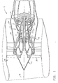
- a gas turbine aircraft engine is designated in its entirety by the reference number 10.
- the engine 10 includes a low pressure rotor (generally designated by 12) and a high pressure rotor (generally designated by 14) rotatably mounted on a stator (generally designated by 16) for rotation about a central axis 18 of the engine.
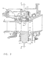
- the rotors 12, 14 have blades 20 arranged in circumferential rows extending generally radially outward from axially spaced disks 22 mounted inside the stator 16. As illustrated in Fig. 2 , each of the blades 20 extends outward from a root 24 adjacent an outer diameter of the corresponding disk 22 to a tip 26 positioned outboard from the root.
- the engine 10 includes a high pressure compressor (generally designated by 30) for compressing flowpath air traveling through the engine, a combustor (generally designated by 32) downstream from the compressor for heating the compressed air, and a high pressure turbine (generally designated by 34) downstream from the combustor for driving the high pressure compressor. Further, the engine 10 includes a low pressure turbine (generally designated by 36) downstream from the high pressure turbine 32 for driving a fan (generally designated by 38) positioned upstream from the high pressure compressor 30.
- a high pressure compressor generally designated by 30
- a combustor downstream from the compressor for heating the compressed air
- a high pressure turbine generally designated by 34 downstream from the combustor for driving the high pressure compressor.
- the engine 10 includes a low pressure turbine (generally designated by 36) downstream from the high pressure turbine 32 for driving a fan (generally designated by 38) positioned upstream from the high pressure compressor 30.
- the stator 16 is a generally tubular structure comprising an annular case 40 and an annular shroud assembly, generally designated by 42, extending generally circumferentially around the central axis 18 ( Fig. 1 ) of the engine 10.
- the shroud assembly 42 includes an annular support 44 mounted locally inside the case 40 and a plurality of shroud segments 46 (e.g., 46 segments) extending substantially continuously around the support.
- the segments 46 are mounted on the support 44 using a conventional arrangement of hangers 48, hooks 52 and clips 54 to define a substantially cylindrical inner surface 56 of the shroud assembly 42 which surrounds the blade tips 26. All of the previously described features of the aircraft engine 10 are conventional and will not be described in further detail.
- the shroud assembly 42 (and more particularly the support 44) is cooled to reduce the radius of the inner surface 56. This cooling is accomplished by withdrawing relatively cool air from the compressor flowpath (e.g., from the fifth and ninth stages of the compressor 30), and directing this cool compressor air through pipes (not shown) extending outside the stator case 40 to the cavity formed between the case and the support 44 and to a similar cavity in the stator of the low pressure turbine 36 ( Fig. 1 ). This air locally cools the stator 16 to reduce its thermal deflections.
- the support 44 is not cooled uniformly over the entire circumference. As a result, the support becomes thermally distorted and is not round when the cooling air is introduced. However, when the cooling air flow is stopped, the support 44 returns to a substantially circular configuration.
- the method of the present invention minimizes the clearances 60 during flight at a preselected steady state operating condition such as a cruise condition. Because the engine 10 operates for long periods of time at cruise, the greatest efficiency and temperature reduction benefits are realized by minimizing clearances 60 during this operating condition.
- the stator inner surfaces 56 In order to minimize the clearances 60 during flight, the stator inner surfaces 56 must be substantially circular during flight. If the radius of the inner surface 56 varies circumferentially around the assembly 42, then larger than optimal clearances will be present where the radius is larger than the minimum radius.
- a pre-machined radial clearance 60 during flight of the aircraft engine is determined at each of a plurality of circumferentially spaced locations around the shroud assembly 42.
- this determination may be made in other ways, in one embodiment this determination is made by examining historical data from a fleet of engines. Further, although the determination may be made at other numbers of circumferentially spaced locations around the assembly 42, in one embodiment the determination is made at locations corresponding to the circumferential center of each shroud segment 46.
- the pre-machined clearances 60 are determined from historical data, it is unnecessary to determine either the radius of the rotor blade tips 26 during flight or the radial displacements of the shroud assembly 42 during flight at the aforesaid plurality of circumferentially spaced locations around the shroud assembly. Rather, the pre-machined clearances 60 are determined by measuring after flight an average radial length by which the rotor blades were shortened during flight due to their tips 26 being abraded by the inner surface 56 of the shroud assembly 42.
- the change in diameter of the tips after flight represents twice the amount the blades were shortened during flight due to the tips 26 being abraded.
- the circumferential locations where the blade tips 26 contacted the inner surface 56 of the shroud assembly 42 during flight are determined by visual inspection after flight. From these observations, the pre-machined in flight clearances can be determined. Because there are variations in the initial clearances throughout the fleet of engines and different initial clearances produce different contact patterns, fairly accurate in flight clearances can be determined using conventional and well understood analyses.
- the pre-machined clearances may be determined by examining historical data from the particular engine 10 for which the shroud assembly 42 is being machined rather than by examining data from a fleet of engines. Still further, it is envisioned that rather than examining historical data to determine the pre-machined clearances 60, theoretical in flight clearances may be calculated at a plurality of circumferential locations without departing from the scope of the present invention.
- the inner surface 56 of the shroud assembly 42 is machined based on the pre-machined radial clearances to provide a generally uniform post-machined radial clearance during flight between the rotor blade tips 26 and the inner surface of the shroud assembly at each of the circumferentially spaced locations around the shroud assembly.
- the amount of material removed from the inner surface 56 at any circumferential location is inversely proportional to the pre-machined clearance 60 at that location.
- the resulting shroud assembly 42 has an inner surface 56 which is spaced from the central axis 18 of the engine 10 by a distance 70 which varies circumferentially around the central axis before flight but which is substantially uniform during flight to minimize operating clearances 60 between the inner surface and the blade tips 26.
- this distance 70 may vary in other ways without departing from the scope of the present invention, in one embodiment intended for use in a high pressure turbine 32 of a CFM56-3 engine available from CFM International, SA, a corporation of France, the inner surface has an overall maximum distance 72 located at an angle 74 of about 135 degrees measured clockwise from a top 76 of the assembly 42 and from a position aft of the surface. This maximum distance 72 is about 36.6014 cm
- the inner surface 56 may have other minimum distances without departing from the scope of the present invention, in one embodiment the minimum distance 78 is about 36.576 cm (14.400 inches). Further, in one embodiment the inner surface 56 has a locally maximum distance 80 at an angle 82 of about 315 degrees measured clockwise from the top 76 and from the aft position. This second locally maximum distance 80 is about 14.405 inches or about 0.0127 cm (0.005 inches) larger than the minimum distance 78 of the inner surface 56.
- the inner surface 56 may be spaced from the center central axis 18 of the engine 10 by other distances 70 without departing from the scope of the present invention.
- the distances 70, 72, 78, 80 may be shortened to match the shorter blades.
- the blades 20 are about 0.0508 cm (0.020 inches) shorter than nominal, the distances 70 may be reduced by 0.0508 cm (0.020 inches) to match the blades.
- aircraft engines other than the CFM56-3 engine will have different distances 70, 72, 78, 80, and different angles 74, 82.
- This inner surface configuration can be obtained by grinding the surface 56 to a radius of about 36.576 cm (14.400 inches) about a first grinding center 18 corresponding to the center of the support 42. Then the surface 56 is ground to a radius of about 36,5633 cm (14.395 inches) about a second grinding center 84 offset by a distance 86 of about 0.0381 cm (0.015 inches) from the first grinding center 18 in a first direction extending about 135 degrees from the top 76 of the assembly measured clockwise from an aft side of the support 42.
- the surface 56 is ground to a radius of about 36.5506 cm (14.390 inches) about a third grinding center 88 offset by a distance 90 of about 0.0381 cm (0.015 inches) from the first grinding center 18 in a second direction generally opposite to the first direction.
- alternative inner surface 56 configurations may be obtained by grinding the surface to different radii than those identified above. For example, if the engine 10 is assembled with shorter blades 20, the radii may be shortened to match the shorter blades. If the blades 20 are about 0.0508 cm (0.020 inches) shorter than nominal, the radii may be reduced by 0.0508 cm (0.020 inches) to match the blades.
Landscapes
- Engineering & Computer Science (AREA)
- Mechanical Engineering (AREA)
- General Engineering & Computer Science (AREA)
- Turbine Rotor Nozzle Sealing (AREA)
- Electrical Discharge Machining, Electrochemical Machining, And Combined Machining (AREA)
Applications Claiming Priority (2)
| Application Number | Priority Date | Filing Date | Title |
|---|---|---|---|
| US09/785,765 US6409471B1 (en) | 2001-02-16 | 2001-02-16 | Shroud assembly and method of machining same |
| US785765 | 2001-02-16 |
Publications (3)
| Publication Number | Publication Date |
|---|---|
| EP1233148A2 EP1233148A2 (en) | 2002-08-21 |
| EP1233148A3 EP1233148A3 (en) | 2005-09-14 |
| EP1233148B1 true EP1233148B1 (en) | 2012-10-17 |
Family
ID=25136566
Family Applications (1)
| Application Number | Title | Priority Date | Filing Date |
|---|---|---|---|
| EP02251042A Expired - Lifetime EP1233148B1 (en) | 2001-02-16 | 2002-02-15 | Shroud assembly and method of machining the same |
Country Status (6)
| Country | Link |
|---|---|
| US (1) | US6409471B1 (enExample) |
| EP (1) | EP1233148B1 (enExample) |
| JP (1) | JP4156246B2 (enExample) |
| BR (1) | BR0200352B1 (enExample) |
| CA (1) | CA2370219C (enExample) |
| SG (1) | SG98475A1 (enExample) |
Families Citing this family (22)
| Publication number | Priority date | Publication date | Assignee | Title |
|---|---|---|---|---|
| JP4698847B2 (ja) * | 2001-01-19 | 2011-06-08 | 三菱重工業株式会社 | ガスタービン分割環 |
| US6906808B2 (en) * | 2002-05-30 | 2005-06-14 | General Electric Company | Methods and apparatus for measuring a surface contour of an object |
| US6931751B2 (en) * | 2002-08-28 | 2005-08-23 | General Electric Company | Methods and apparatus for securing components for inspection |
| US6886422B2 (en) * | 2002-10-09 | 2005-05-03 | General Electric Co. | Methods and apparatus for inspecting components |
| US6842995B2 (en) * | 2002-10-09 | 2005-01-18 | General Electric Company | Methods and apparatus for aligning components for inspection |
| US6890150B2 (en) * | 2003-08-12 | 2005-05-10 | General Electric Company | Center-located cutter teeth on shrouded turbine blades |
| ITMI20041781A1 (it) | 2004-09-17 | 2004-12-17 | Nuovo Pignone Spa | Dispositivo di protezione per uno statore di una turbina |
| US7207771B2 (en) * | 2004-10-15 | 2007-04-24 | Pratt & Whitney Canada Corp. | Turbine shroud segment seal |
| JP4764219B2 (ja) * | 2006-03-17 | 2011-08-31 | 三菱重工業株式会社 | ガスタービンのシール構造 |
| WO2007138489A2 (en) * | 2006-06-01 | 2007-12-06 | Rajiv Muradia | Remote health care system with treatment verification |
| US7871244B2 (en) * | 2007-02-15 | 2011-01-18 | Siemens Energy, Inc. | Ring seal for a turbine engine |
| EP2141328A1 (en) * | 2008-07-03 | 2010-01-06 | Siemens Aktiengesellschaft | Sealing system between a shroud segment and a rotor blade tip and manufacturing method for such a segment |
| EP2189630A1 (de) | 2008-11-19 | 2010-05-26 | Siemens Aktiengesellschaft | Gasturbine, Leitschaufelträger für eine solche Gasturbine und Gas- bzw. Dampfturbinenanlage mit einer solchen Gasturbine |
| US20140321993A1 (en) * | 2011-01-07 | 2014-10-30 | General Electric Company | Elliptical sealing system |
| US20120177484A1 (en) * | 2011-01-07 | 2012-07-12 | General Electric Company | Elliptical Sealing System |
| US9874218B2 (en) | 2011-07-22 | 2018-01-23 | Hamilton Sundstrand Corporation | Minimal-acoustic-impact inlet cooling flow |
| US9833869B2 (en) * | 2013-02-11 | 2017-12-05 | United Technologies Corporation | Blade outer air seal surface |
| FR3002273B1 (fr) * | 2013-02-20 | 2017-06-23 | Snecma | Dispositif avionique pour la surveillance d'une turbomachine |
| GB201309580D0 (en) * | 2013-05-29 | 2013-07-10 | Siemens Ag | Rotor tip clearance |
| EP3078448B1 (en) * | 2015-04-10 | 2018-07-11 | Rolls-Royce Deutschland Ltd & Co KG | Method for machining a casing for a turbo engine. |
| US11428241B2 (en) * | 2016-04-22 | 2022-08-30 | Raytheon Technologies Corporation | System for an improved stator assembly |
| EP3434864B1 (en) * | 2017-07-27 | 2020-12-16 | General Electric Company | A method and system for repairing a turbomachine |
Family Cites Families (14)
| Publication number | Priority date | Publication date | Assignee | Title |
|---|---|---|---|---|
| DE2740192C2 (de) | 1977-09-07 | 1981-11-12 | Mtu Motoren- Und Turbinen-Union Muenchen Gmbh, 8000 Muenchen | Spaltdichtung für eine um ihre Längsachse verstellbare, axial umströmte Leitschaufel einer Strömungsmaschine |
| US4363599A (en) | 1979-10-31 | 1982-12-14 | General Electric Company | Clearance control |
| US4767272A (en) | 1987-10-14 | 1988-08-30 | United Technologies Corporation | Method for reducing blade tip variation of a bladed rotor |
| US4999991A (en) | 1989-10-12 | 1991-03-19 | United Technologies Corporation | Synthesized feedback for gas turbine clearance control |
| US5054997A (en) * | 1989-11-22 | 1991-10-08 | General Electric Company | Blade tip clearance control apparatus using bellcrank mechanism |
| US5281085A (en) * | 1990-12-21 | 1994-01-25 | General Electric Company | Clearance control system for separately expanding or contracting individual portions of an annular shroud |
| GB9103809D0 (en) | 1991-02-23 | 1991-04-10 | Rolls Royce Plc | Blade tip clearance control apparatus |
| US5212940A (en) * | 1991-04-16 | 1993-05-25 | General Electric Company | Tip clearance control apparatus and method |
| US5462403A (en) * | 1994-03-21 | 1995-10-31 | United Technologies Corporation | Compressor stator vane assembly |
| US5439348A (en) | 1994-03-30 | 1995-08-08 | United Technologies Corporation | Turbine shroud segment including a coating layer having varying thickness |
| US5639210A (en) * | 1995-10-23 | 1997-06-17 | United Technologies Corporation | Rotor blade outer tip seal apparatus |
| US5667358A (en) | 1995-11-30 | 1997-09-16 | Westinghouse Electric Corporation | Method for reducing steady state rotor blade tip clearance in a land-based gas turbine to improve efficiency |
| GB2313414B (en) | 1996-05-24 | 2000-05-17 | Rolls Royce Plc | Gas turbine engine blade tip clearance control |
| US6467339B1 (en) * | 2000-07-13 | 2002-10-22 | United Technologies Corporation | Method for deploying shroud segments in a turbine engine |
-
2001
- 2001-02-16 US US09/785,765 patent/US6409471B1/en not_active Expired - Fee Related
-
2002
- 2002-01-31 CA CA002370219A patent/CA2370219C/en not_active Expired - Fee Related
- 2002-02-05 SG SG200200670A patent/SG98475A1/en unknown
- 2002-02-14 BR BRPI0200352-0A patent/BR0200352B1/pt not_active IP Right Cessation
- 2002-02-15 JP JP2002037525A patent/JP4156246B2/ja not_active Expired - Fee Related
- 2002-02-15 EP EP02251042A patent/EP1233148B1/en not_active Expired - Lifetime
Also Published As
| Publication number | Publication date |
|---|---|
| EP1233148A3 (en) | 2005-09-14 |
| BR0200352A (pt) | 2002-10-08 |
| SG98475A1 (en) | 2003-09-19 |
| JP4156246B2 (ja) | 2008-09-24 |
| BR0200352B1 (pt) | 2010-12-14 |
| JP2002256812A (ja) | 2002-09-11 |
| CA2370219A1 (en) | 2002-08-16 |
| EP1233148A2 (en) | 2002-08-21 |
| CA2370219C (en) | 2009-06-09 |
| US6409471B1 (en) | 2002-06-25 |
Similar Documents
| Publication | Publication Date | Title |
|---|---|---|
| EP1233148B1 (en) | Shroud assembly and method of machining the same | |
| US5228828A (en) | Gas turbine engine clearance control apparatus | |
| US5018942A (en) | Mechanical blade tip clearance control apparatus for a gas turbine engine | |
| EP2546471B1 (en) | Tip clearance control for turbine blades | |
| US6406256B1 (en) | Device and method for the controlled setting of the gap between the stator arrangement and rotor arrangement of a turbomachine | |
| US5161944A (en) | Shroud assemblies for turbine rotors | |
| US10436070B2 (en) | Blade outer air seal having angled retention hook | |
| EP1676978B1 (en) | Gas turbine engine blade tip clearance apparatus and method | |
| EP0492865A1 (en) | Clearance control system | |
| EP1630385A2 (en) | Method and apparatus for maintaining rotor assembly tip clearances | |
| US20100284794A1 (en) | Low pressure turbine rotor disk | |
| EP1113146A2 (en) | Rotatory machine having a seal assembly | |
| US7614845B2 (en) | Turbomachine inner casing fitted with a heat shield | |
| EP0475771B1 (en) | Compressor case construction | |
| JP2002256812A5 (enExample) | ||
| EP2236757B1 (en) | Split rotor disk assembly for a gas turbine engine | |
| US6896484B2 (en) | Turbine engine sealing device | |
| EP1774141B1 (en) | Turbine case reinforcement in a gas turbine jet engine | |
| EP3269940A1 (en) | Compressor and corresponding gas turbine engine with such a compressor | |
| EP2636850B1 (en) | Stator of a gas turbine | |
| EP2009250A2 (en) | Annular turbine casing of a gas turbine engine and corresponding turbine assembly | |
| EP1268982B1 (en) | Gas turbine engine stator case | |
| EP0618349A1 (en) | A turbine assembly for a gas turbine engine | |
| US11970946B2 (en) | Clearance control assembly | |
| EP3896263B1 (en) | Spoked thermal control ring for a high pressure compressor case clearance control system |
Legal Events
| Date | Code | Title | Description |
|---|---|---|---|
| PUAI | Public reference made under article 153(3) epc to a published international application that has entered the european phase |
Free format text: ORIGINAL CODE: 0009012 |
|
| AK | Designated contracting states |
Kind code of ref document: A2 Designated state(s): AT BE CH CY DE DK ES FI FR GB GR IE IT LI LU MC NL PT SE TR |
|
| AX | Request for extension of the european patent |
Free format text: AL;LT;LV;MK;RO;SI |
|
| PUAL | Search report despatched |
Free format text: ORIGINAL CODE: 0009013 |
|
| AK | Designated contracting states |
Kind code of ref document: A3 Designated state(s): AT BE CH CY DE DK ES FI FR GB GR IE IT LI LU MC NL PT SE TR |
|
| AX | Request for extension of the european patent |
Extension state: AL LT LV MK RO SI |
|
| RIC1 | Information provided on ipc code assigned before grant |
Ipc: 7F 01D 25/26 B Ipc: 7F 01D 5/00 B Ipc: 7F 01D 11/24 B Ipc: 7F 01D 11/18 B Ipc: 7F 01D 9/02 B Ipc: 7F 01D 11/08 A |
|
| 17P | Request for examination filed |
Effective date: 20060314 |
|
| AKX | Designation fees paid |
Designated state(s): DE FR GB |
|
| GRAP | Despatch of communication of intention to grant a patent |
Free format text: ORIGINAL CODE: EPIDOSNIGR1 |
|
| GRAS | Grant fee paid |
Free format text: ORIGINAL CODE: EPIDOSNIGR3 |
|
| GRAA | (expected) grant |
Free format text: ORIGINAL CODE: 0009210 |
|
| AK | Designated contracting states |
Kind code of ref document: B1 Designated state(s): DE FR GB |
|
| REG | Reference to a national code |
Ref country code: GB Ref legal event code: FG4D |
|
| REG | Reference to a national code |
Ref country code: DE Ref legal event code: R096 Ref document number: 60243867 Country of ref document: DE Effective date: 20121213 |
|
| PGFP | Annual fee paid to national office [announced via postgrant information from national office to epo] |
Ref country code: GB Payment date: 20130528 Year of fee payment: 12 Ref country code: DE Payment date: 20130530 Year of fee payment: 12 |
|
| PLBE | No opposition filed within time limit |
Free format text: ORIGINAL CODE: 0009261 |
|
| STAA | Information on the status of an ep patent application or granted ep patent |
Free format text: STATUS: NO OPPOSITION FILED WITHIN TIME LIMIT |
|
| PGFP | Annual fee paid to national office [announced via postgrant information from national office to epo] |
Ref country code: FR Payment date: 20130702 Year of fee payment: 12 |
|
| 26N | No opposition filed |
Effective date: 20130718 |
|
| REG | Reference to a national code |
Ref country code: DE Ref legal event code: R097 Ref document number: 60243867 Country of ref document: DE Effective date: 20130718 |
|
| REG | Reference to a national code |
Ref country code: DE Ref legal event code: R119 Ref document number: 60243867 Country of ref document: DE |
|
| GBPC | Gb: european patent ceased through non-payment of renewal fee |
Effective date: 20140215 |
|
| REG | Reference to a national code |
Ref country code: FR Ref legal event code: ST Effective date: 20141031 |
|
| REG | Reference to a national code |
Ref country code: DE Ref legal event code: R119 Ref document number: 60243867 Country of ref document: DE Effective date: 20140902 |
|
| PG25 | Lapsed in a contracting state [announced via postgrant information from national office to epo] |
Ref country code: GB Free format text: LAPSE BECAUSE OF NON-PAYMENT OF DUE FEES Effective date: 20140215 Ref country code: FR Free format text: LAPSE BECAUSE OF NON-PAYMENT OF DUE FEES Effective date: 20140228 Ref country code: DE Free format text: LAPSE BECAUSE OF NON-PAYMENT OF DUE FEES Effective date: 20140902 |