EP1232965A1 - Wheel for conveyor with jointed elements for conveying materials - Google Patents
Wheel for conveyor with jointed elements for conveying materials Download PDFInfo
- Publication number
- EP1232965A1 EP1232965A1 EP01830051A EP01830051A EP1232965A1 EP 1232965 A1 EP1232965 A1 EP 1232965A1 EP 01830051 A EP01830051 A EP 01830051A EP 01830051 A EP01830051 A EP 01830051A EP 1232965 A1 EP1232965 A1 EP 1232965A1
- Authority
- EP
- European Patent Office
- Prior art keywords
- conveyor
- wheel
- inserts
- sound
- depressions
- Prior art date
- Legal status (The legal status is an assumption and is not a legal conclusion. Google has not performed a legal analysis and makes no representation as to the accuracy of the status listed.)
- Withdrawn
Links
Images


Classifications
-
- B—PERFORMING OPERATIONS; TRANSPORTING
- B65—CONVEYING; PACKING; STORING; HANDLING THIN OR FILAMENTARY MATERIAL
- B65G—TRANSPORT OR STORAGE DEVICES, e.g. CONVEYORS FOR LOADING OR TIPPING, SHOP CONVEYOR SYSTEMS OR PNEUMATIC TUBE CONVEYORS
- B65G17/00—Conveyors having an endless traction element, e.g. a chain, transmitting movement to a continuous or substantially-continuous load-carrying surface or to a series of individual load-carriers; Endless-chain conveyors in which the chains form the load-carrying surface
- B65G17/06—Conveyors having an endless traction element, e.g. a chain, transmitting movement to a continuous or substantially-continuous load-carrying surface or to a series of individual load-carriers; Endless-chain conveyors in which the chains form the load-carrying surface having a load-carrying surface formed by a series of interconnected, e.g. longitudinal, links, plates, or platforms
- B65G17/08—Conveyors having an endless traction element, e.g. a chain, transmitting movement to a continuous or substantially-continuous load-carrying surface or to a series of individual load-carriers; Endless-chain conveyors in which the chains form the load-carrying surface having a load-carrying surface formed by a series of interconnected, e.g. longitudinal, links, plates, or platforms the surface being formed by the traction element
-
- B—PERFORMING OPERATIONS; TRANSPORTING
- B65—CONVEYING; PACKING; STORING; HANDLING THIN OR FILAMENTARY MATERIAL
- B65G—TRANSPORT OR STORAGE DEVICES, e.g. CONVEYORS FOR LOADING OR TIPPING, SHOP CONVEYOR SYSTEMS OR PNEUMATIC TUBE CONVEYORS
- B65G23/00—Driving gear for endless conveyors; Belt- or chain-tensioning arrangements
- B65G23/02—Belt- or chain-engaging elements
- B65G23/04—Drums, rollers, or wheels
- B65G23/06—Drums, rollers, or wheels with projections engaging abutments on belts or chains, e.g. sprocket wheels
-
- B—PERFORMING OPERATIONS; TRANSPORTING
- B65—CONVEYING; PACKING; STORING; HANDLING THIN OR FILAMENTARY MATERIAL
- B65G—TRANSPORT OR STORAGE DEVICES, e.g. CONVEYORS FOR LOADING OR TIPPING, SHOP CONVEYOR SYSTEMS OR PNEUMATIC TUBE CONVEYORS
- B65G2201/00—Indexing codes relating to handling devices, e.g. conveyors, characterised by the type of product or load being conveyed or handled
- B65G2201/02—Articles
Definitions
- the present invention relates to a wheel for a jointed conveyor for conveying materials, comprising a peripheral surface engaging functionally with the conveyor.
- wheels for driving jointed conveyors for conveying materials are fundamentally of the pulley type, with a continuous functional surface in engagement with the opposing surface of the conveyor itself, or of the type having radially projecting teeth forming depressions which receive the hinge pins of the various constituent elements of the jointed conveyor.
- the pulley type of wheel is used in practice only as an idle wheel on a fixed spindle for the return of the jointed conveyor
- the type with teeth and depressions is preferably used to transmit to the conveyor the power taken from the shaft on which the wheel is mounted, although its use as a return or guiding or tensioning member is not to be ruled out.
- the wheels and jointed-element conveyors of the type indicated above are made of metallic or plastic materials which, as they come into contact with one another during the movement, generate a large amount of noise as they knock together.
- the object of the present invention is therefore to eliminate or at least greatly reduce the amount of noise generated by materials conveying systems.
- the number 1 is a general reference for a wheel whose peripheral surface for functional engagement with a conveyor is marked 2.
- the wheel has a peripheral groove, marked 3, the functional surface 2 therefore being positioned on either side of this.
- the wheel 1 has a conventional hub 4 for idle mounting on a shaft (not shown) which, for the particular type of wheel illustrated, is normally fixed.
- the peripheral surface engaging functionally with the jointed conveyor comprises two annular elements marked 5, each housed a respective groove 6.
- the depth of the grooves 6 is less than the radial thickness of the annular elements housed in them to enable them to project partially from the surface 2, and it is these that come into contact with the conveyor as it wraps around the wheel.
- the annular elements 5, which may also be toroidal in form, that is with a circular cross section, are made of a sound-damping material, particularly an elastomeric material such as natural or synthetic rubber.
- the wheel 7 is of the type in which the peripheral surface 8 that engages functionally with the conveyor has radial teeth 9, and depressions 10 between pairs of adjacent teeth.
- the peripheral surface 8 has grooves 11 passing radially through the teeth 9 and the bottom 12 of the depressions 10.
- annular elements 13 Placed in the said grooves 11 are annular elements 13 made of a sound-damping material, particularly an elastomeric material such as natural or synthetic rubber.
- the depth of the grooves 11 below the bottom 12 of the depressions 10 is such as to be less than the radial thickness of the annular elements 13 or of the diameter of their cross section if they are toroidal.
- each annular element 13 projects radially above the bottom 12 of the depressions 10 to provide sound-damping contact with the conveyor.
- FIGS 5 and 6 illustrate a wheel 14 with teeth 15 and depressions 16, like the wheel 7 of Figures 3 and 4, in which the sound-damping elements consist of thin blocks 17 positioned in the depressions 16 and fixed by conventional means, such as adhesives, to the bottoms of the said depressions.
- the abovementioned blocks 17, which extend laterally at least a short way up the flanks of the teeth 15, are made of a sound-damping material, particularly an elastomeric material, e.g. natural or synthetic rubber.
- a wheel for example such as the wheel 14 of Figures 5 and 6, engages with a conveyor 18 composed of flat elements 19 hinged to each other by pins 20 and slots 21, as is conventional in this specific technological sector.
Abstract
Wheel (14) for conveyor (18) composed of jointed
elements (19) for conveying materials, comprising a
peripheral surface engaging functionally with the
conveyor (18) and having radial teeth (15) and
depressions (16) formed between pairs of adjacent teeth,
as well as inserts (17) of sound-damping material
positioned in the said depressions (16), at the bottom
thereof, the said inserts coming into physical contact
with the conveyor (18) during operation. By this means
the noise produced by the impact between the conveyor
(18) and the wheel (14) is eliminated.
Description
- The present invention relates to a wheel for a jointed conveyor for conveying materials, comprising a peripheral surface engaging functionally with the conveyor.
- As is known, wheels for driving jointed conveyors for conveying materials are fundamentally of the pulley type, with a continuous functional surface in engagement with the opposing surface of the conveyor itself, or of the type having radially projecting teeth forming depressions which receive the hinge pins of the various constituent elements of the jointed conveyor.
- Whereas the pulley type of wheel is used in practice only as an idle wheel on a fixed spindle for the return of the jointed conveyor, the type with teeth and depressions is preferably used to transmit to the conveyor the power taken from the shaft on which the wheel is mounted, although its use as a return or guiding or tensioning member is not to be ruled out.
- In accordance with the prior art, the wheels and jointed-element conveyors of the type indicated above are made of metallic or plastic materials which, as they come into contact with one another during the movement, generate a large amount of noise as they knock together.
- In the particular case of materials conveying, as for example in packaging businesses or in appliance assembly lines, the presence of numerous conveyors of the above type generates a large aggregate amount of environmental noise which can cause sometimes permanent problems for operators present in the work environment.
- The object of the present invention is therefore to eliminate or at least greatly reduce the amount of noise generated by materials conveying systems.
- This and other objects which will become clear in the course of the following description are achieved with the wheel for jointed-element conveyors in accordance with the accompanying claims.
- The invention will now be described in greater detail with reference to a number of practical examples of embodiments. These examples are given purely by way of non-limiting indication and are illustrated in the accompanying drawings, in which:
- Figure 1 is a perspective view of a wheel with a continuous peripheral surface intended for functional engagement and having annular sound-damping inserts according to the invention;
- Figure 2 is a cross section through the wheel shown in Figure 1 taken on II-II;
- Figure 3 is a perspective view of a wheel in which the functionally engaging peripheral surface has radial teeth and depressions and annular sound-damping inserts according to the invention;
- Figure 4 is a cross section through the wheel shown in Figure 3 taken on IV-IV;
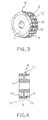
- Figure 5 is a perspective view of a wheel in which the functionally engaging peripheral surface has radial teeth and depressions and sound-damping inserts in the form of thin blocks;
- Figure 6 is a cross section through the wheel shown in Figure 5 taken on VI-VI; and
- Figure 7 is a cross section showing the coupling between a length of conveyor composed of jointed elements and a wheel with a functionally engaging peripheral surface having radial teeth and depressions and sound-damping inserts in the form of thin blocks.
-
- Referring to the aforesaid figures and in particular Figures 1 and 2, the number 1 is a general reference for a wheel whose peripheral surface for functional engagement with a conveyor is marked 2.
- In the example shown in Figure 1 the wheel has a peripheral groove, marked 3, the
functional surface 2 therefore being positioned on either side of this. - The wheel 1 has a conventional hub 4 for idle mounting on a shaft (not shown) which, for the particular type of wheel illustrated, is normally fixed.
- In accordance with the invention, the peripheral surface engaging functionally with the jointed conveyor comprises two annular elements marked 5, each housed a
respective groove 6. - The depth of the
grooves 6 is less than the radial thickness of the annular elements housed in them to enable them to project partially from thesurface 2, and it is these that come into contact with the conveyor as it wraps around the wheel. - The
annular elements 5, which may also be toroidal in form, that is with a circular cross section, are made of a sound-damping material, particularly an elastomeric material such as natural or synthetic rubber. - With reference to the example illustrated in Figures 3 and 4, the
wheel 7 is of the type in which the peripheral surface 8 that engages functionally with the conveyor hasradial teeth 9, anddepressions 10 between pairs of adjacent teeth. - The peripheral surface 8 has
grooves 11 passing radially through theteeth 9 and thebottom 12 of thedepressions 10. - Placed in the said
grooves 11 areannular elements 13 made of a sound-damping material, particularly an elastomeric material such as natural or synthetic rubber. - The depth of the
grooves 11 below thebottom 12 of thedepressions 10 is such as to be less than the radial thickness of theannular elements 13 or of the diameter of their cross section if they are toroidal. - In this way a part of each
annular element 13 projects radially above thebottom 12 of thedepressions 10 to provide sound-damping contact with the conveyor. - Referring to the example shown in Figures 5 and 6, these illustrate a
wheel 14 withteeth 15 anddepressions 16, like thewheel 7 of Figures 3 and 4, in which the sound-damping elements consist ofthin blocks 17 positioned in thedepressions 16 and fixed by conventional means, such as adhesives, to the bottoms of the said depressions. - The
abovementioned blocks 17, which extend laterally at least a short way up the flanks of theteeth 15, are made of a sound-damping material, particularly an elastomeric material, e.g. natural or synthetic rubber. - Referring to Figure 7, it will be observed that a wheel, for example such as the
wheel 14 of Figures 5 and 6, engages with aconveyor 18 composed offlat elements 19 hinged to each other bypins 20 andslots 21, as is conventional in this specific technological sector. - It can be seen that the impact between the
conveyor 19 and thewheel 14 takes place, in theslots 21, on the sound-damping blocks 17 placed in the bottoms of thedepressions 16. - The operation of the
wheels 1 and 7 is much the same, the impact between theconveyor 18 and the functionally engaging peripheral surface occurring on theannular elements - The absorption of the kinetic energy of the impact into the
annular elements blocks 17, which are made of an elastomeric material, reduces the production of vibrations and hence the generation of noise during operation of the conveyor. - The dimensions, materials and type of wheels used to drive the conveyors can of course be varied to suit user requirements without departing from the scope of the present invention as described above and as claimed below.
Claims (9)
- Wheel for conveyor (18) composed of jointed elements (19) for conveying materials, comprising a peripheral surface (2, 8) engaging functionally with the conveyor (18), characterized in that at least part of the said surface is provided with inserts (5, 13, 17) of sound-damping material, the said inserts being in physical contact with the conveyor (18).
- Wheel according to Claim 1, characterized in that the said peripheral surface (2) engaging functionally with the conveyor (18) is continuous and the said inserts of sound-damping material consist of at least one annular element (5) that runs circumferentially around the said peripheral surface.
- Wheel according to Claim 2, characterized in that it comprises a pair of annular elements (5) side by side and axially separate from each other, each of the said annular elements (5) being housed in its own circumferential groove (6) formed in the said surface.
- Wheel according to Claim 1, characterized in that said peripheral surface engaging functionally with the conveyor has radial teeth (15) and depressions (16) between pairs of adjacent teeth and in that the said inserts (17) of sound-damping material are positioned in the said depressions (16), at the bottom thereof.
- Wheel according to Claim 4, characterized in that the said inserts (17) of sound-damping material extend also over at least a portion of the flank of at least one of the pairs of adjacent teeth (15) that define the said depressions (16).
- Wheel according to Claims 4 and 5, characterized in that the said inserts (17) of sound-damping material consist of blocks placed parallel to the axis of rotation of the wheel.
- Wheel according to Claim 4, characterized in that the said inserts consist of at least one annular element (13) running circumferentially around the said peripheral surface for functional engagement with the conveyor, the said annular element (13) being housed in a corresponding circumferential groove (11) passing radially through the said teeth (9) and below the bottoms (12) of the depressions (10) present between the pairs of teeth (9).
- Wheel according to Claim 7, characterized in that it comprises a pair of the said annular elements (13) positioned side by side and axially separate from each other.
- Wheel according to Claims 1 to 8, characterized in that the sound-damping material of the said inserts is an elastomeric material such as natural and/or synthetic rubber.
Priority Applications (1)
| Application Number | Priority Date | Filing Date | Title |
|---|---|---|---|
| EP01830051A EP1232965A1 (en) | 2001-01-26 | 2001-01-26 | Wheel for conveyor with jointed elements for conveying materials |
Applications Claiming Priority (1)
| Application Number | Priority Date | Filing Date | Title |
|---|---|---|---|
| EP01830051A EP1232965A1 (en) | 2001-01-26 | 2001-01-26 | Wheel for conveyor with jointed elements for conveying materials |
Publications (1)
| Publication Number | Publication Date |
|---|---|
| EP1232965A1 true EP1232965A1 (en) | 2002-08-21 |
Family
ID=8184373
Family Applications (1)
| Application Number | Title | Priority Date | Filing Date |
|---|---|---|---|
| EP01830051A Withdrawn EP1232965A1 (en) | 2001-01-26 | 2001-01-26 | Wheel for conveyor with jointed elements for conveying materials |
Country Status (1)
| Country | Link |
|---|---|
| EP (1) | EP1232965A1 (en) |
Cited By (4)
| Publication number | Priority date | Publication date | Assignee | Title |
|---|---|---|---|---|
| WO2005009874A2 (en) * | 2003-07-29 | 2005-02-03 | Pulsar S.R.L. | Waste gatherless conveying apparatus |
| GB2410516A (en) * | 2004-01-29 | 2005-08-03 | Dbt Gmbh | Sprocket wheel for chain driven conveyors |
| US6935483B2 (en) * | 2003-09-16 | 2005-08-30 | Rapistan Systems Advertising Corp. | Metal frame sorter with wear strip |
| CN102826345A (en) * | 2012-09-18 | 2012-12-19 | 昆山特力伯传动科技有限公司 | Low-noise conveying component |
Citations (4)
| Publication number | Priority date | Publication date | Assignee | Title |
|---|---|---|---|---|
| EP0068475A2 (en) * | 1981-06-30 | 1983-01-05 | Draadindustrie Jonge Poerink B.V. | Muffled plate conveyor belt |
| DE3125698A1 (en) * | 1981-06-30 | 1983-01-13 | Deutsche Bundespost, vertreten durch den Präsidenten des Fernmeldetechnischen Zentralamtes, 6100 Darmstadt | Noise-damping arrangement in conveyor apparatuses |
| EP0560480A2 (en) * | 1992-02-20 | 1993-09-15 | Mcg Techno Pack Limited | Drive means for slat conveyors |
| EP1038806A2 (en) * | 1999-03-22 | 2000-09-27 | Ets Denis | Chain conveying device and cooperating tooth wheel |
-
2001
- 2001-01-26 EP EP01830051A patent/EP1232965A1/en not_active Withdrawn
Patent Citations (4)
| Publication number | Priority date | Publication date | Assignee | Title |
|---|---|---|---|---|
| EP0068475A2 (en) * | 1981-06-30 | 1983-01-05 | Draadindustrie Jonge Poerink B.V. | Muffled plate conveyor belt |
| DE3125698A1 (en) * | 1981-06-30 | 1983-01-13 | Deutsche Bundespost, vertreten durch den Präsidenten des Fernmeldetechnischen Zentralamtes, 6100 Darmstadt | Noise-damping arrangement in conveyor apparatuses |
| EP0560480A2 (en) * | 1992-02-20 | 1993-09-15 | Mcg Techno Pack Limited | Drive means for slat conveyors |
| EP1038806A2 (en) * | 1999-03-22 | 2000-09-27 | Ets Denis | Chain conveying device and cooperating tooth wheel |
Cited By (6)
| Publication number | Priority date | Publication date | Assignee | Title |
|---|---|---|---|---|
| WO2005009874A2 (en) * | 2003-07-29 | 2005-02-03 | Pulsar S.R.L. | Waste gatherless conveying apparatus |
| WO2005009874A3 (en) * | 2003-07-29 | 2005-06-30 | Pulsar Srl | Waste gatherless conveying apparatus |
| US6935483B2 (en) * | 2003-09-16 | 2005-08-30 | Rapistan Systems Advertising Corp. | Metal frame sorter with wear strip |
| GB2410516A (en) * | 2004-01-29 | 2005-08-03 | Dbt Gmbh | Sprocket wheel for chain driven conveyors |
| GB2410516B (en) * | 2004-01-29 | 2006-10-04 | Dbt Gmbh | Sprocket wheel for underground mining |
| CN102826345A (en) * | 2012-09-18 | 2012-12-19 | 昆山特力伯传动科技有限公司 | Low-noise conveying component |
Similar Documents
| Publication | Publication Date | Title |
|---|---|---|
| CA1060235A (en) | Belt drive system | |
| US3257860A (en) | Vibration and shock insulating sprocket | |
| US4714371A (en) | System for the transmission of power | |
| US20060100051A1 (en) | Belt drive assembly for driving accessory parts of an internal combustion engine, drive belt and pulleys suited to be used in said assembly | |
| JPH08506649A (en) | Stress dissipative gear and manufacturing method thereof | |
| WO2006054842A3 (en) | Outer rotor of motor for direct drive-type washing machine | |
| EP0926394B1 (en) | Double-meshing-type silent chain and sprocket for meshing with the chain along outer circumference thereof | |
| GB2270550A (en) | Chain drive mechanism having improved noise reduction | |
| EP1232965A1 (en) | Wheel for conveyor with jointed elements for conveying materials | |
| CN100485222C (en) | Resin gear and rotational power transmission member of resin | |
| WO2004042251A3 (en) | Super drive conveyor belt | |
| JPH0611610B2 (en) | Chain wheel for conveyor | |
| ATE285537T1 (en) | TRANSMISSION, ESPECIALLY FOR BALANCER SHAFTS OF INTERNATIONAL ENGINE | |
| WO2004009278A1 (en) | Ring saw drive device and cutting device with ring saw | |
| SE463858B (en) | CIRCULAR SAW KING AND RING SAW WITH DRIVING ORGANIZATION | |
| US5829306A (en) | Gear shock absorbing mechanism | |
| US6142900A (en) | Sprocket with thin body and grooved teeth | |
| CA2517042A1 (en) | Rotation tool | |
| DE60322948D1 (en) | STEP-FREE GEAR | |
| US8371780B2 (en) | Rotationally drivable cutting or milling tool and method, and use of such a cutting tool for producing driving and conveyor belts | |
| EP0426678B1 (en) | Device for eliminating rattle in a gear box | |
| WO2003030296A3 (en) | Rotor for vane pump | |
| SE8902542D0 (en) | DRIVE WHEEL FOR CHAIN SAW | |
| CA2674130C (en) | Feed wheel | |
| JP4371007B2 (en) | PRESSING BELT AND MANUFACTURING METHOD THEREOF |
Legal Events
| Date | Code | Title | Description |
|---|---|---|---|
| PUAI | Public reference made under article 153(3) epc to a published international application that has entered the european phase |
Free format text: ORIGINAL CODE: 0009012 |
|
| AK | Designated contracting states |
Kind code of ref document: A1 Designated state(s): AT BE CH CY DE DK ES FI FR GB GR IE IT LI LU MC NL PT SE TR |
|
| AX | Request for extension of the european patent |
Free format text: AL;LT;LV;MK;RO;SI |
|
| AKX | Designation fees paid | ||
| REG | Reference to a national code |
Ref country code: DE Ref legal event code: 8566 |
|
| STAA | Information on the status of an ep patent application or granted ep patent |
Free format text: STATUS: THE APPLICATION IS DEEMED TO BE WITHDRAWN |
|
| 18D | Application deemed to be withdrawn |
Effective date: 20030222 |