EP1232887A2 - Door frame structure of motor vehicle - Google Patents
Door frame structure of motor vehicle Download PDFInfo
- Publication number
- EP1232887A2 EP1232887A2 EP02003601A EP02003601A EP1232887A2 EP 1232887 A2 EP1232887 A2 EP 1232887A2 EP 02003601 A EP02003601 A EP 02003601A EP 02003601 A EP02003601 A EP 02003601A EP 1232887 A2 EP1232887 A2 EP 1232887A2
- Authority
- EP
- European Patent Office
- Prior art keywords
- frame
- door frame
- door
- moulding
- peripheral wall
- Prior art date
- Legal status (The legal status is an assumption and is not a legal conclusion. Google has not performed a legal analysis and makes no representation as to the accuracy of the status listed.)
- Granted
Links
- 238000000465 moulding Methods 0.000 claims abstract description 142
- 230000002093 peripheral effect Effects 0.000 claims abstract description 77
- 239000011521 glass Substances 0.000 claims abstract description 50
- 229920003002 synthetic resin Polymers 0.000 claims abstract description 8
- 239000000057 synthetic resin Substances 0.000 claims abstract description 8
- 238000007789 sealing Methods 0.000 claims abstract description 4
- 229910052751 metal Inorganic materials 0.000 claims description 6
- 239000002184 metal Substances 0.000 claims description 6
- 229920002725 thermoplastic elastomer Polymers 0.000 claims description 3
- 238000005452 bending Methods 0.000 description 7
- 229920002397 thermoplastic olefin Polymers 0.000 description 5
- 239000000463 material Substances 0.000 description 4
- 239000002390 adhesive tape Substances 0.000 description 3
- 229910052782 aluminium Inorganic materials 0.000 description 3
- XAGFODPZIPBFFR-UHFFFAOYSA-N aluminium Chemical compound [Al] XAGFODPZIPBFFR-UHFFFAOYSA-N 0.000 description 3
- 230000003247 decreasing effect Effects 0.000 description 3
- 229920001971 elastomer Polymers 0.000 description 3
- 238000001746 injection moulding Methods 0.000 description 3
- 238000000034 method Methods 0.000 description 3
- 229920002943 EPDM rubber Polymers 0.000 description 2
- 239000004743 Polypropylene Substances 0.000 description 2
- 229910000831 Steel Inorganic materials 0.000 description 2
- 229920000122 acrylonitrile butadiene styrene Polymers 0.000 description 2
- 238000010622 cold drawing Methods 0.000 description 2
- 239000000806 elastomer Substances 0.000 description 2
- -1 polypropylene Polymers 0.000 description 2
- 229920001155 polypropylene Polymers 0.000 description 2
- 239000010959 steel Substances 0.000 description 2
- 239000011248 coating agent Substances 0.000 description 1
- 238000000576 coating method Methods 0.000 description 1
- 238000001125 extrusion Methods 0.000 description 1
- 238000012986 modification Methods 0.000 description 1
- 230000004048 modification Effects 0.000 description 1
- 230000003014 reinforcing effect Effects 0.000 description 1
- 239000007779 soft material Substances 0.000 description 1
- 238000003466 welding Methods 0.000 description 1
Images



Classifications
-
- B—PERFORMING OPERATIONS; TRANSPORTING
- B60—VEHICLES IN GENERAL
- B60J—WINDOWS, WINDSCREENS, NON-FIXED ROOFS, DOORS, OR SIMILAR DEVICES FOR VEHICLES; REMOVABLE EXTERNAL PROTECTIVE COVERINGS SPECIALLY ADAPTED FOR VEHICLES
- B60J5/00—Doors
- B60J5/04—Doors arranged at the vehicle sides
- B60J5/0401—Upper door structure
- B60J5/0402—Upper door structure window frame details, including sash guides and glass runs
-
- B—PERFORMING OPERATIONS; TRANSPORTING
- B60—VEHICLES IN GENERAL
- B60J—WINDOWS, WINDSCREENS, NON-FIXED ROOFS, DOORS, OR SIMILAR DEVICES FOR VEHICLES; REMOVABLE EXTERNAL PROTECTIVE COVERINGS SPECIALLY ADAPTED FOR VEHICLES
- B60J10/00—Sealing arrangements
- B60J10/15—Sealing arrangements characterised by the material
- B60J10/16—Sealing arrangements characterised by the material consisting of two or more plastic materials having different physical or chemical properties
-
- B—PERFORMING OPERATIONS; TRANSPORTING
- B60—VEHICLES IN GENERAL
- B60J—WINDOWS, WINDSCREENS, NON-FIXED ROOFS, DOORS, OR SIMILAR DEVICES FOR VEHICLES; REMOVABLE EXTERNAL PROTECTIVE COVERINGS SPECIALLY ADAPTED FOR VEHICLES
- B60J10/00—Sealing arrangements
- B60J10/20—Sealing arrangements characterised by the shape
- B60J10/23—Sealing arrangements characterised by the shape assembled from two or more parts
- B60J10/235—Sealing arrangements characterised by the shape assembled from two or more parts the parts being joined along their longitudinal direction
-
- B—PERFORMING OPERATIONS; TRANSPORTING
- B60—VEHICLES IN GENERAL
- B60J—WINDOWS, WINDSCREENS, NON-FIXED ROOFS, DOORS, OR SIMILAR DEVICES FOR VEHICLES; REMOVABLE EXTERNAL PROTECTIVE COVERINGS SPECIALLY ADAPTED FOR VEHICLES
- B60J10/00—Sealing arrangements
- B60J10/20—Sealing arrangements characterised by the shape
- B60J10/24—Sealing arrangements characterised by the shape having tubular parts
-
- B—PERFORMING OPERATIONS; TRANSPORTING
- B60—VEHICLES IN GENERAL
- B60J—WINDOWS, WINDSCREENS, NON-FIXED ROOFS, DOORS, OR SIMILAR DEVICES FOR VEHICLES; REMOVABLE EXTERNAL PROTECTIVE COVERINGS SPECIALLY ADAPTED FOR VEHICLES
- B60J10/00—Sealing arrangements
- B60J10/20—Sealing arrangements characterised by the shape
- B60J10/24—Sealing arrangements characterised by the shape having tubular parts
- B60J10/248—Sealing arrangements characterised by the shape having tubular parts having two or more tubular cavities, e.g. formed by partition walls
-
- B—PERFORMING OPERATIONS; TRANSPORTING
- B60—VEHICLES IN GENERAL
- B60J—WINDOWS, WINDSCREENS, NON-FIXED ROOFS, DOORS, OR SIMILAR DEVICES FOR VEHICLES; REMOVABLE EXTERNAL PROTECTIVE COVERINGS SPECIALLY ADAPTED FOR VEHICLES
- B60J10/00—Sealing arrangements
- B60J10/20—Sealing arrangements characterised by the shape
- B60J10/26—Sealing arrangements characterised by the shape characterised by the surface shape
- B60J10/265—Sealing arrangements characterised by the shape characterised by the surface shape the surface being primarily decorative
-
- B—PERFORMING OPERATIONS; TRANSPORTING
- B60—VEHICLES IN GENERAL
- B60J—WINDOWS, WINDSCREENS, NON-FIXED ROOFS, DOORS, OR SIMILAR DEVICES FOR VEHICLES; REMOVABLE EXTERNAL PROTECTIVE COVERINGS SPECIALLY ADAPTED FOR VEHICLES
- B60J10/00—Sealing arrangements
- B60J10/30—Sealing arrangements characterised by the fastening means
-
- B—PERFORMING OPERATIONS; TRANSPORTING
- B60—VEHICLES IN GENERAL
- B60J—WINDOWS, WINDSCREENS, NON-FIXED ROOFS, DOORS, OR SIMILAR DEVICES FOR VEHICLES; REMOVABLE EXTERNAL PROTECTIVE COVERINGS SPECIALLY ADAPTED FOR VEHICLES
- B60J10/00—Sealing arrangements
- B60J10/70—Sealing arrangements specially adapted for windows or windscreens
- B60J10/74—Sealing arrangements specially adapted for windows or windscreens for sliding window panes, e.g. sash guides
-
- B—PERFORMING OPERATIONS; TRANSPORTING
- B60—VEHICLES IN GENERAL
- B60J—WINDOWS, WINDSCREENS, NON-FIXED ROOFS, DOORS, OR SIMILAR DEVICES FOR VEHICLES; REMOVABLE EXTERNAL PROTECTIVE COVERINGS SPECIALLY ADAPTED FOR VEHICLES
- B60J10/00—Sealing arrangements
- B60J10/80—Sealing arrangements specially adapted for opening panels, e.g. doors
- B60J10/84—Sealing arrangements specially adapted for opening panels, e.g. doors arranged on the vehicle body
-
- B—PERFORMING OPERATIONS; TRANSPORTING
- B60—VEHICLES IN GENERAL
- B60J—WINDOWS, WINDSCREENS, NON-FIXED ROOFS, DOORS, OR SIMILAR DEVICES FOR VEHICLES; REMOVABLE EXTERNAL PROTECTIVE COVERINGS SPECIALLY ADAPTED FOR VEHICLES
- B60J10/00—Sealing arrangements
- B60J10/80—Sealing arrangements specially adapted for opening panels, e.g. doors
- B60J10/86—Sealing arrangements specially adapted for opening panels, e.g. doors arranged on the opening panel
- B60J10/88—Sealing arrangements specially adapted for opening panels, e.g. doors arranged on the opening panel mounted on, or integral with, the glass-run seals
Definitions
- the present invention relates to a door frame structure of a motor vehicle and, more particularly, to a door frame structure having a frame moulding.
- a door 10 of a motor vehicle has a door frame 12 around a window opening 14. And a glass run (not shown) is attached to an inner side of the door frame 12 while a door weather strip (not shown) is attached to an outer side of the door frame 12.
- FIG.2 illustrates one example of a conventional door frame structure of a vehicle, which is taken along the line X-X of FIG. 1.
- the door frame 12 is composed of a metal plate.
- the door frame 12 includes a flat peripheral wall 16 which extends around the window opening 14(FIG. 1), a vertical outside wall 18 which is formed at an outside end of the flat peripheral wall 16, and a protrusion 20 having a closed cross-section, which protrudes along an inside end of the flat peripheral wall 16.
- the peripheral wall 16, the vertical outside wall 18, and an outside surface of the protrusion 20 define a channel 22 on an inner side of the flat peripheral wall 16.
- the channel 22 has a generally U-shaped cross-section opening towards the window opening 14.
- a glass run 24 is attached in the channel 22.
- the glass run 24 has seal lips 26 and 28 which respectively project inwardly from ends of opposite side walls 30 and 32 thereof for holding a periphery of the door glass 34 from both sides thereof.
- a retainer 36 is provided on an outer side of the peripheral wall 16, and a door weather strip 38 having a base portion 40, a tubular main seal portion 42 and a sub-seal lip portion 44 is attached to the door frame 12 by fitting the base portion 40 in the retainer 36.
- a flange 46 is defined by peripheral portions of an inner body panel 48, outer body panel 50 and reinforcing panel 52 which are joined with each other. And an opening weather strip 54 having a tubular seal portion 56 is attached to the flange 46.
- the protrusion 20 of the door frame 12 contacts and presses the seal portion 56 of the opening weather strip 54
- the main seal portion 42 of the door weather strip 38 contacts and presses the door opening portion of the outer body panel 50
- an end of the sub-seal lip portion 44 contacts and presses the door opening portion outside the main seal portion 42.
- the cross-section of the door frame structure which is taken along the line Y-Y of FIG. 1, is substantially identical to that shown in FIG.2. Accordingly, explanations thereof will be omitted.
- the metal door frames are generally coated, but coating color is difficult to select freely.
- synthetic resins enable the free selection of color and gloss thereof, and accordingly, by virtue of the frame mouldings composed of synthetic resins, designing around door frames can be freely chosen.
- frame mouldings are attached to door frames by engaging projections formed along side edges of the frame moulding with side edges of a vertical outside wall of the door frame, or by securing the frame moulding to the vertical outside wall of the door frame with clips which are provided in the frame moulding.
- attaching methods are, however, troublesome.
- the frame moulding is bonded to the door frame using double-sided adhesive tapes. This attaching method also has the problem that sufficient care must be taken to bond the frame moulding without offset in the attaching position.
- the door frame structures including frame mouldings have another problem that there occurs a large level difference between an outside surface of the door glass and an outside surface of the frame moulding.
- the large level difference degrades appearances around vehicle doors, and undesirably enlarges air resistance therearound during running of motor vehicles. Accordingly, it is desired to decrease such level difference to a minimum.
- the side wall 32 of the glass run 24, which has the seal lip 28, is located outside the door glass 34, and the vertical outside wall 18 of the door frame 12 is further located outside the side wall 32 to form a level difference S.
- the frame moulding is provided outside the vertical outside wall 18, the level difference is much enlarged.
- the door frame structure in accordance with the present invention includes a metal door frame which has a flat peripheral wall extending around a periphery of a vehicle door to define a window opening, and a protrusion protruding from an inside end of the flat peripheral wall towards the window opening.
- a glass run for receiving a door glass which is in closed position is provided on an inner side of the peripheral wall of the door frame, and a door weather strip for sealing between the door frame and a door opening portion of a vehicle body is provided on an outer side of the flat peripheral wall of the door frame.
- a frame moulding for covering the door frame which has a plate-like configuration and is composed of a synthetic resin or thermoplastic elastomer, extends along the door frame and is secured to the outside end of the flat peripheral wall of the door frame at about right angles to the flat peripheral wall.
- the protrusion and the flat peripheral wall of the door frame, and an inner half part of the frame moulding, which protrudes into the window opening inwardly of the outside end of the flat peripheral wall of the door frame, define a channel for providing the glass run therein.
- said frame moulding is secured to the outside end of said flat peripheral wall in about a widthwise center of said frame moulding.
- the glass run includes a main body having a generally U-shaped cross-section, and seal portions projecting inwardly from opening ends of opposite side walls of the main body to seal the door glass on both sides thereof, and the main body of the glass run is fitted in the channel.
- the inner half part of the frame moulding has a seal portion at an inner end thereof, and an L-shaped member is fitted along the flat peripheral wall and the protrusion of the door frame, and the L-shaped member has a seal portion at an inner end thereof so as to face the seal portion of the inner half part of the frame moulding.
- the inner half part of the frame moulding and the L-shaped member define the glass run.
- the frame moulding has a pair of shelf-like projections which respectively project from about a widthwise center of an inside surface of the frame moulding at about right angles thereto so as to be spaced from each other.
- the frame moulding has a shelf-like projection which projects from about a widthwise center of an inside surface of the frame moulding at about right angles thereto, and the flat peripheral wall of the door frame includes a pair of walls which are spaced from each other. And by fitting the shelf-like projection of the frame moulding between the pair of walls of the flat peripheral wall of the door frame, the frame moulding is secured to the door frame.
- the door frame has an outside wall which stands on an outside end of said peripheral wall and an outer half part of said frame moulding is fixed to the outside surface of said outside wall.
- the frame moulding serves as a vertical outside wall of a conventional door frame, and accordingly, the resultant door frame structure becomes simple.
- the door frame does not have a conventional vertical outside wall so that the level difference between the frame moulding and the door glass is made small, and the weight of the door frame is reduced.
- the frame moulding can be secured to the door frame with high work efficiency.
- FIGS. 3(A) illustrates an upper rear corner of a frame moulding of a front door of a vehicle
- FIG. 3(B) and 3(C) are cross-sectional views of a first embodiment of the present invention, which are respectively taken along the lines IIIB-IIIB and IIIC-IIIC of FIG. 3(A).
- a door frame 12A is formed by bending a steel plate by a roller-bending work.
- the door frame 12A has a flat peripheral wall 60 composed of three sheets of steel plate, which are welded to one another, a tubular protrusion 62 which protrudes from an inside end of the flat peripheral wall 60 towards a window opening, and an engaging part 64 having a C-shaped cross-section, which is formed on an upper side of the peripheral wall 60.
- the door frame 12A does not have any conventional vertical outside wall like the wall 18 of the conventional door frame 12 (FIG.2).
- the door frame 12A is composed of an upper frame member 66 (FIG. 3(B)) which extends along a roof side of a vehicle body, and a vertical frame member 68 (FIG.3(C)) which extends along a center pillar of the vehicle body.
- These frame members 66 and 68 have a substantially identical cross-section to each other, and are joined to each other by welding at an upper rear corner of the door frame 12A.
- the upper frame member 66 is first formed straight, and then curved by bending to conform to a door opening portion along the roof side.
- the upper frame member 66 has no vertical outside wall, and accordingly, can be readily curved with a small bending force.
- a frame moulding 70 for covering an outside of the door frame 12A is composed of a synthetic resin such as ABS resin, polypropylene or the like, and is formed by injection molding.
- the upper frame member 66 is covered with an upper frame moulding 70A and the vertical frame member 68 is covered with a vertical frame moulding 70B.
- the frame moulding 70 may be also composed of thermoplastic olefin elastomer.
- the upper frame moulding 70A includes a main body 72 having a generally uniform width over an entire length thereof, and a pair of shelf-like projections 74 and 76 which respectively project from about a widthwise center of an inside surface of the frame moulding 70A at about right angles thereto.
- the projections 74 and 76 are respectively formed over an entire length of the frame moulding 70A to have a thickness slightly less than that of the main portion 72.
- the projections 74 and 76 face each other through a space. At a closed end of the space, the width thereof is slightly greater than the thickness of the peripheral wall 60 composed of three pieces of metal plate, and at an open end thereof, the width is made slightly less than the thickness of the peripheral wall 60.
- the upper frame moulding 70A is secured to the upper frame member 66 by press-inserting the outside end of the peripheral wall 60 of the upper frame member 66 between the opposite ends of the projections 74 and 76 while enlarging the space therebetween, and pushing the main body 72 onto the outside end of the peripheral wall 60.
- the main body 72 of the upper frame moulding 70A thus secured has an inner half part 78 which protrudes inwardly of the peripheral wall 60, and faces the protrusion 62 of the door frame 12A.
- These inner half part 78 of the upper frame moulding 70A, the protrusion 62 and the peripheral wall 60 of which a lower surface is covered with the projection 76 define a channel 80 having a generally U-shaped cross-section which opens downwardly.
- a projection 82 is formed along a lower end of the lower half part 78 so as to project inwardly.
- a glass run 84 is fitted in the channel 80.
- the glass run 84 has a generally U-shaped cross-section and includes side walls 86 and 88, and seal lips 90 and 92 which project inwardly from open ends of the side walls 86 and 88.
- the seal lips 90 and 92 seal an upper periphery of the door glass 34 on both sides thereof.
- the upper frame moulding 70A further includes an outer half part 94 which extends outwardly of the peripheral wall 60 of the upper frame portion 66.
- the outer half part 94 has a projection 96 which projects inwardly from an upper end thereof to define an L-like engaging part which faces the C-shaped engaging part 64 of the upper frame member 66.
- a door weather strip 98 is attached on an outer side of the peripheral wall 60 of the upper frame member 66.
- the door weather strip 98 includes a base portion 100, a tubular main seal portion 102, and a sub-seal lip portion 104.
- the C-shaped engaging part 64 and the L-shaped engaging part 96 engage widthwise ends of the base portion 100 of the door weather strip 98, thereby serving as a retainer for the door weather strip 98.
- the configurations of the vertical frame moulding 70B is identical to those of the upper frame moulding 70A except that the width of the vertical frame moulding gradually enlarges downwardly.
- FIG. 3(C) parts similar to those in FIG. 3(B) are given the same number as in FIG. 3(B).
- the width of the outer half part 94 of the vertical frame moulding 70B gradually enlarges downwardly.
- the projections 74 and 76 which respectively project from the inside surface of the vertical frame moulding 70B are located at about a width center thereof, and extend downwardly in parallel with an end edge of the inner half part 78.
- the engaging part 96 is located at an outer end edge of the outer half part 94 of the frame moulding 70B. The engaging part 96 extends downwardly in parallel with the projection 74.
- the vertical frame moulding 70B thus arranged is secured to the peripheral wall 60 of a vertical frame member 68 using the projections 74 and 76.
- a glass run 84 is fitted in the channel 80 of the vertical frame moulding 70B, and the base portion 100 of the door weather strip 98 is engaged by the C-shaped engaging part 64 of the vertical frame member 68 and the engaging part 96 of the vertical frame moulding 70B.
- the frame moulding 70 can be secured to the door frame 12A in a prescribed position with high work efficiency by inserting the outside end of the peripheral wall 60 of the door frame 12A between the projections 74 and 76 of the frame moulding 70, and pushing the frame moulding 70 onto the door frame 12A.
- the door frame 12A does not have a conventional vertical outside wall at an outside end thereof. Accordingly, the weight of the door frame 12A is reduced, the material costs thereof become inexpensive, and the level difference between the outside surfaces of the door glass 34 and the frame moulding 70 occurring along a periphery thereof can be decreased.
- the width of the frame moulding 70 can be arbitrarily varied so that the vehicle doors and the vehicle bodies therearound can be designed freely.
- FIG. 4 illustrates a cross-section of a second embodiment of a door frame structure of the present invention, which is taken along the line IIIB-IIIB of FIG. 3(A).
- the arrangement of the present embodiment, which differs from the first embodiment, will be mainly explained.
- a peripheral wall 106 of an upper frame member 108 of a door frame 12B has a tubular cylindrical outside end 110 of which the diameter is slightly greater than the thickness of a flat part of the peripheral wall 106.
- Projections 112 and 114 of a frame moulding 70C respectively have a thin-walled base, thereby defining concave facing surfaces for receiving the tubular cylindrical outside end 110.
- the thin-walled bases of the projections 112 and 114 fit with the tubular cylindrical outside end 110 of the peripheral wall 106 to prevent the projections 112 and 114 from slipping along the peripheral wall 106.
- An engaging part 116 projects from an outer end of an outer half part 118 of a main body 120 of the frame moulding 70C and bends downwardly to define a downwardly opening groove having a U-shaped cross-section with the main body 120.
- An outside end of a base portion 122 of a door weather strip 124 has a configuration which fits in the groove defined by the engaging part 116 and the main body 120, thereby attaching the base portion 122 to the upper frame member 108.
- the door frame structure around a vertical frame member (not shown) of the door frame 12B is substantially identical to that around the upper frame member 108, which is illustrated in FIG. 4.
- the remaining arrangements of the door frame structure of the door frame 12B are substantially identical to those of FIGS. 3(A), 3(B) and 3(C), therefore, explanations thereof will be omitted.
- FIG. 5 illustrates a cross-section of a third embodiment of a door frame structure of the present invention, which is taken along the line IIIB-IIIB of FIG. 3(A).
- the arrangement of the present embodiment, which differs from the first embodiment, will be mainly explained.
- a door frame 12C is composed of aluminum, and is formed by cold drawing.
- An outside end portion 126 of a peripheral wall 128 of an upper frame member 130 has an arrowhead-like cross-section, and projections 132 and 134 of a frame moulding 70D respectively have a bending end 136.
- the bending ends 136 of the projections 132 and 134 fit with the arrowhead-like outside end portion 126 to prevent the projections 132 and 134 from slipping along the peripheral wall 128.
- An engaging part 138 having a C-like cross-section is integrally formed with the peripheral wall 128 on an upper side thereof so as to face an engaging part 140 projecting from an outer end of a main portion of the frame moulding 70D.
- the door frame structure around a vertical frame portion (not shown) of the door frame 12C is substantially identical to that around the upper frame portion 130, which is shown in FIG. 5.
- the remaining arrangements of the door frame structure of the door frame 12C are substantially identical to those of FIGS. 3(A), 3(B) and 3(C), therefore, explanations thereof will be omitted.
- the door frame is composed of an aluminum material. Accordingly, the door frame can be made light, and readily formed into a desired cross-sectional shape.
- frame mouldings for covering vertical frame members of door frames respectively have a downwardly enlarging width.
- frame mouldings, each having a uniform width may be used.
- the frame moulding having a uniform width may be formed by extrusion.
- FIG. 6 illustrates a cross-section of a fourth embodiment of a door frame structure of the present invention, which is taken along the line IIIB-IIIB of FIG. 3(A).
- the arrangement of the present embodiment, which differs from the first embodiment, will be mainly explained.
- a door frame 12D is composed of aluminum, and is formed by cold drawing.
- a peripheral wall 142 of an upper frame portion 144 of the door frame 12D includes an upper wall 146 and a lower wall 148 which project towards the outside of a vehicle body in approximately parallel with each other. The space between the upper and lower walls 146 and 148 is slightly small at projecting ends thereof.
- a shelf-like projection 150 projects from an inside surface of a frame moulding 70E, and a projecting end of the projection 150 has an arrowhead-like cross-section. When the frame moulding 70E is attached, the projection 150 having an arrowhead-like cross-section fits with the upper and lower walls 146 and 148 of the upper frame member 144 to prevent the projection 150 from slipping along the peripheral wall 142.
- a door weather strip 152 has a tubular main seal member 154 and a sub-seal member 156, which are formed separately from each other.
- the main seal member 154 is secured to the upper frame member 144 with clips which are integrally formed in a base part 157 of the main seal member 154.
- An engaging part 158 having a C-like cross-section is integrally formed with the peripheral wall 142 on an upper side thereof.
- the engaging part 158 faces an engaging part 160 which projects from an upper end of a main part of the frame moulding 70E.
- the door frame structure around a vertical frame portion (not shown) of the door frame 12D is substantially identical to that around the upper frame member 144, which is illustrated in FIG. 6.
- the remaining arrangements of the door frame structure of the door frame 12D are substantially identical to those of FIGS. 3(A), 3(B) and 3(C).
- FIG. 7 illustrates a cross-section of a fifth embodiment of a door frame structure of the present invention, which is taken along the line IIIB-IIIB of FIG. 3(A).
- the arrangement of the present embodiment is substantially identical to that of the first embodiment, which is illustrated in FIG. 3(B), except that the frame moulding of the fifth embodiment serves as one part of a glass run as well as one part of a door weather strip. With the arrangement of the present embodiment, a simple door frame structure can be effected.
- a seal portion 162 is formed along an inner end of a main body 164 of a frame moulding 70F integrally therewith, and a seal lip 166 is formed along an outer end of the main part 164 of the frame moulding 70F integrally therewith.
- These seal portion 162 and the seal lip 166 are composd of a soft material such as a soft rubber or thermoplastic elastomer.
- the frame moulding 70F is secured to a peripheral wall 168 of an upper frame member 170 of a door frame 12E using a pair of projections 172 and 174 of the frame moulding 70F.
- a seal lip 188 is formed along an end of the inside wall 178, and an outside end of the bottom wall 180 fits into a recess 190 formed in an inside surface of the frame moulding 70F.
- the inner half part 184 of the main body 164 of the frame moulding 70F and the L-shaped glass run member 176 define a glass run.
- An engaging part 192 is integrally formed with the peripheral wall 168 on an upper side thereof.
- the engaging part 192 faces an engaging part 194 which projects from an outer end of the main body 164 of the frame moulding 70F.
- These engaging parts 192 and 194 engage with a door weather strip 196 which has a tubular seal portion but does not have a sub-seal lip portion.
- the seal lip 166 serves as the sub-seal portion.
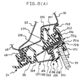
- FIGS. 8(A) and 8(B) are cross-sectional views of a sixth embodiment of the present invention, which are respectively taken along the lines X-X and Y-Y of FIG. 1.
- the arrangement of the present embodiment is partly identical to that of the fifth embodiment, which is illustrated in FIG. 7.
- an upper frame moulding 70G is attached to an outside surface of an upper frame member 198
- a vertical frame moulding 70H is attached to an outside surface of a vertical frame member 200.
- These frame mouldings 70G and 70H are composed of a synthetic resin such as ABS resin, polypropylene or the like, or thermoplastic olefin elastomer (TPO), and are respectively formed by injection molding into configurations which integrally covers the outside surfaces of the upper frame member 198 and the vertical frame member 200.
- the upper frame member 198 has an outside wall 202 which stands on an outside end of a peripheral wall 206.
- An outer half part of the upper frame moulding 70G is bonded to the outside surface of the outside wall 202 with a double-sided adhesive tape 204, and an inner half part thereof protrudes inwardly of an outside end of the peripheral wall 206 of the upper frame portion 198 towards a window opening.
- a seal lip 208 is integrally formed with the frame moulding 70G along an outer end thereof.
- the seal lip 208 is composed of EPDM rubber or TPO, which is softer than a main body of the upper frame moulding 70G.
- a seal portion 210 is formed integrally with the frame moulding 70G along an inner end thereof.
- the seal portion 210 is composed of the same material as that of the seal lip 208, and has a configuration which slightly protrudes from the inside surface of the upper frame moulding 70G into a triangular cross-section.
- an outside wall 212 of the vertical frame member 200 of the door frame 12F has a width greater than the outside wall 202 of the upper frame member 198.
- the vertical frame moulding 70H for covering the outside wall 212 of the vertical frame member 200 has a width greater than that of the upper frame moulding 70G.
- the outer half part of the vertical frame moulding 70H is bonded to the outside wall 212 with a double-sided adhesive tape 214.
- the inner half part of the vertical frame moulding 70H protrudes inwardly of the outside wall 212 towards a window opening.
- a lip-shaped seal portion 216 composed of the same material as that of the seal portions 208 and 210 is integrally formed along an inner end of the frame moulding 70H so as to extend obliquely inwardly.
- the seal portions 208, 210, and 216 are integrally formed with the upper frame moulding 70G and the vertical frame moulding 70G by injection molding.
- the main body of each of the frame mouldings 70G and 70H is colored glossy black.
- a glass run member 218 having a generally L-shaped cross-section is attached to an inner periphery of the door frame 12F.
- the L-shaped glass run member 218 is composed of an extruded body of EPDM rubber or TPO.
- An upper glass run member 218A, which is to be attached to the upper frame member 198, and a vertical glass run member 218B, which is to be attached to the vertical frame member 200, are joined by molding at approximately right angles to each other.
- the L-shaped glass run member 218 has a seal lip portion 220 along an end edge of a side wall 222.
- the L-shaped glass run member 218 is attached to the door frame 12F over the entire length thereof by positioning the side wall 222 and the other side wall 224 thereof along a tubular protrusion 226 and the peripheral wall 206 of the door frame 12F, respectively, and engaging steps formed in the side wall 222 with steps formed in the protrusion 226 while fitting an outside end edge of the side wall 224 in a recess 228 formed in the inside surface of the frame moulding 70G.
- the L-shaped glass run member 218 and the inner half part of each of the frame mouldings 70G and 70H define a glass run 230 having a generally U-shaped cross-section, which includes seal portions 210 (216) and 220 projecting inwardly from ends of opposite side walls to seal the periphery of the door glass 34 on both sides thereof.
- a door weather strip 232 including a base portion 234 and a tubular seal portion 236 is attached to a retainer 238 on an outer side of the door frame 12F.
- the structure around a door opening portion of a vehicle body is substantially identical to that of the conventional structure shown in FIG. 2, and accordingly, explanations thereof will be omitted.
- the frame moulding serves as one side wall of the glass run. Accordingly, the level difference between the outside surface of the frame moulding and the outside surface of the door glass can be further reduced.
- the seal lip which is formed along an end edge of the outer half part of the frame moulding for contacting and pressing the door opening portion of the vehicle body upon closing of the vehicle door, no seal lip is needed in the door weather strip.
- the frame moulding for covering the door frame can be attached with a high work efficiency and without any offset in attachment position.
- the frame moulding is attached around the flat peripheral wall of the door frame without providing an outside wall therein, and accordingly, the weight of the door frame can be decreased, and the level difference between the outside surface of the door glass and the outside surface of the frame moulding can be reduced to improve the appearance around the vehicle door, and decrease the air resistance during running of vehicles.
- the designing around the door frame can be freely chosen merely by changing the configuration and color h of the frame moulding without changing the structure of the door frame.
Landscapes
- Engineering & Computer Science (AREA)
- Mechanical Engineering (AREA)
- Seal Device For Vehicle (AREA)
- Motor Or Generator Frames (AREA)
Abstract
Description
Claims (10)
- A door frame structure of a vehicle, comprising:a door frame (12A-12D) composed of metal, said door frame including a flat peripheral wall (60; 106; 128; 142; 168; 206) which extends around a periphery of a vehicle door to define a window opening, and a protrusion (62; 186; 226) which protrudes from an inside end of said flat peripheral wall;a glass run (84; 176) for receiving a door glass (34) which is in an elevated position, said glass run being attached on an inner side of said flat peripheral wall of said door frame;a door weather strip (98; 124; 152; 196; 232) for sealing between the door frame and a door opening portion of a vehicle body, said door weather strip is attached on an outer side of said flat peripheral wall of said door frame; anda frame moulding (70; 70C-70H) for covering an outside end of said flat peripheral wall of said door frame, said frame moulding having a plate-like configuration, and being composed of one of a synthetic resin and a thermoplastic elastomer, said frame moulding extending along said door frame and being secured to said outside end of said flat peripheral wall of said door frame at about right angles to said flat peripheral wall, said protrusion of said door frame (62; 186; 226), said flat peripheral wall (60; 106; 128; 142; 168; 206) of said door frame and an inner half part of said frame moulding, which extends into the window opening inwardly of said outside end of said flat peripheral wall of said door frame, defining a channel (80; 182) for providing said glass run (84; 176; 230).
- A door frame structure as claimed in claim 1, wherein said frame moulding (70; 70C-70H) is secured to the outside end of said flat peripheral wall (60; 106; 128; 142; 168; 206) in about a widthwise center of said frame moulding.
- A door frame structure as claimed in claim 1 or 2, wherein said glass run (84) has a generally U-shaped cross-section, and has seal portions (90, 92) at opening ends for sealing inside and outside surfaces of the door glass (34), and said glass run is fitted in said channel.
- A door frame structure as claimed in claim 1 or 2, wherein said inner half part of said frame moulding (70F) has a seal portion (162) at an inner end thereof, and an L-shaped member (176) is attached on an inner side of said flat peripheral wall (168) of said door frame so as to extend along said flat peripheral wall and said protrusion (186) of said door frame, and said L-shaped member has a seal portion (188) at an inner end thereof so as to face said seal portion of said inner half part of said frame moulding, whereby said inner half part of said frame moulding and said L-shaped member define said glass run.
- A door frame structure as claimed in claim 1 or 2, wherein said frame moulding has a pair of shelf-like projections (74; 112; 132; 172; 76; 114; 134; 174) which respectively project from about a widthwise center of an inside surface of said frame moulding (70C; 70D; 70F) at about right angles thereto so as to be spaced from each other, and said flat peripheral wall (60; 106; 168) of said door frame is fitted between said pair of shelf-like projections of said frame moulding.
- A door frame structure as claimed in claim 1 or 2, wherein said frame moulding (70E) has a shelf-like projection (150) which projects from about a widthwise center of an inside surface of said frame moulding at about right angles thereto, and said flat peripheral wall (142) of said door frame includes a pair of walls (146, 148) which are spaced from each other, and said shelf-like projection of said frame moulding is fitted between said pair of walls of said flat peripheral wall of said door frame.
- A door frame structure as claimed in claim 1 or 2, wherein an outer half part (94) of said frame moulding (70), which extends from said outside end of said flat peripheral wall (60) of said door frame outwardly of the window opening, has a projection (96) for holding said door weather strip (98).
- A door frame structure as claimed in claim 1 or 2, wherein an outer half part of said frame moulding (70F; 70G), which extends from said outside end of said flat peripheral wall (168; 206) of said door frame, outwardly of the window opening, has a lip (166; 208) composed of a rubber-like elastic body for abutting the door opening portion of the vehicle body when the vehicle door is closed.
- A door frame structure as claimed in claim 1 or 2, wherein said door frame (12A) is composed of an upper frame member (66) which extends along a roof-side of a vehicle body, and a vertical frame member (68) which extends along a center pillar of the vehicle body, said frame moulding (70) has a uniform width in a part for covering said upper frame member of said door frame, and has a downwardly enlarging width in another part for covering said vertical frame member of said door frame.
- A door frame structure according to claim 1 or 2, wherein said door frame (12F) has an outside wall (202; 212) which stands on an outside end of said peripheral wall (206) and an outer half part of said frame moulding (70G;70H) is fixed to the outside surface of said outside wall.
Applications Claiming Priority (4)
| Application Number | Priority Date | Filing Date | Title |
|---|---|---|---|
| JP2001038502A JP2002240565A (en) | 2001-02-15 | 2001-02-15 | Door for automobile |
| JP2001038502 | 2001-02-15 | ||
| JP2001211668A JP3900866B2 (en) | 2001-07-12 | 2001-07-12 | Door frame structure for automobile doors |
| JP2001211668 | 2001-07-12 |
Publications (3)
| Publication Number | Publication Date |
|---|---|
| EP1232887A2 true EP1232887A2 (en) | 2002-08-21 |
| EP1232887A3 EP1232887A3 (en) | 2003-03-05 |
| EP1232887B1 EP1232887B1 (en) | 2007-04-18 |
Family
ID=26609459
Family Applications (1)
| Application Number | Title | Priority Date | Filing Date |
|---|---|---|---|
| EP02003601A Expired - Lifetime EP1232887B1 (en) | 2001-02-15 | 2002-02-15 | Door frame structure of motor vehicle |
Country Status (3)
| Country | Link |
|---|---|
| US (1) | US6679003B2 (en) |
| EP (1) | EP1232887B1 (en) |
| DE (1) | DE60219541T2 (en) |
Cited By (6)
| Publication number | Priority date | Publication date | Assignee | Title |
|---|---|---|---|---|
| WO2004037576A3 (en) * | 2002-10-09 | 2004-05-27 | Metzeler Automotive Profile | Weatherstrip comprising a trim part |
| DE102006002466A1 (en) * | 2006-01-18 | 2007-07-26 | Metzeler Automotive Profile Systems Gmbh | Sealing arrangement e.g. for sealing window panes of motor vehicle, has connecting area with slot and other connecting area with projection, which intervenes for connecting former connecting area and latter connecting area |
| EP2027981A1 (en) * | 2007-08-24 | 2009-02-25 | Hutchinson | Method of manufacturing a top wing module for a vehicle window, and such a module |
| FR2957855A1 (en) * | 2010-03-29 | 2011-09-30 | Peugeot Citroen Automobiles Sa | Sealing module for window i.e. upper window, of rear door utilized to define opening for accessing passenger in car, has outer wheel cover comprising variable width, where width of support is proportional to width of wheel cover |
| EP2537694A1 (en) | 2011-06-24 | 2012-12-26 | Peugeot Citroën Automobiles Sa | Finishing element comprising a door frame cover and a gusset |
| US20190016202A1 (en) * | 2017-07-13 | 2019-01-17 | Nishikawa Rubber Co., Ltd. | Assembly structure of door weather strip |
Families Citing this family (52)
| Publication number | Priority date | Publication date | Assignee | Title |
|---|---|---|---|---|
| DE10259843B3 (en) * | 2002-12-19 | 2004-08-26 | Metzeler Automotive Profile Systems Gmbh | Sealing arrangement, in particular for sealing window panes of a motor vehicle |
| US6814393B2 (en) * | 2003-03-24 | 2004-11-09 | Toyoda Gosei Co., Ltd. | Sealing strip and vehicle panel assembly |
| DE10334065B4 (en) * | 2003-07-25 | 2005-06-23 | Metzeler Automotive Profile Systems Gmbh | Sealing arrangement, in particular for sealing a stationary window pane of a motor vehicle |
| US20050046124A1 (en) * | 2003-08-26 | 2005-03-03 | Schlegel Corporation | Weatherseal with sealing surface having strips of material exhibiting reduced adhesion bonding to frozen water |
| US20050072053A1 (en) * | 2003-10-06 | 2005-04-07 | Filipczak Larry Andrew | Seal and molding assembly |
| JP4257194B2 (en) * | 2003-12-10 | 2009-04-22 | 片山工業株式会社 | Vehicle door sash and manufacturing method thereof |
| US7172239B2 (en) * | 2004-03-19 | 2007-02-06 | Toyoda Gosei Co., Ltd. | Sealing structure for vehicle door |
| US20060010213A1 (en) * | 2004-05-19 | 2006-01-12 | Jignesh Mehta | Method for personal email archiving and organization for electronic data, including email, which can be utilized by both the user and the provider in a variety of ways |
| CA2575801C (en) * | 2004-11-18 | 2014-01-28 | Cooper-Standard Automotive Inc. | Inner garnish assembly |
| JP4809119B2 (en) * | 2006-05-12 | 2011-11-09 | 西川ゴム工業株式会社 | Glass run mounting structure |
| KR100892694B1 (en) * | 2006-11-17 | 2009-04-15 | 현대자동차주식회사 | Car door frame |
| DE602007000723D1 (en) * | 2007-01-12 | 2009-04-30 | Rainforest R & D Ltd | A fastening strip for use with a seal for sealing a window of a vehicle door |
| JP5003384B2 (en) * | 2007-09-27 | 2012-08-15 | 豊田合成株式会社 | Automotive glass run |
| JP4588074B2 (en) * | 2008-01-22 | 2010-11-24 | 西川ゴム工業株式会社 | Sash molding end holding structure |
| CA2719819A1 (en) * | 2008-04-11 | 2009-10-15 | Magna International Inc. | Door structure with co-extruded roll frame |
| US8166708B2 (en) * | 2008-07-30 | 2012-05-01 | Ellis Peter J | Integrated glass run and upper reveal with film |
| JP5711756B2 (en) * | 2009-12-01 | 2015-05-07 | ガーディアン・インダストリーズ・コーポレーション | Improved vehicle sealing system and / or method of manufacturing the same |
| FR2956068B1 (en) * | 2010-02-08 | 2012-04-20 | Hutchinson | EXTERIOR COVER FOR AUTOMOTIVE VEHICLE DOOR FRAME, AND INCORPORATING SEALING MODULE |
| KR101163472B1 (en) | 2010-06-08 | 2012-07-18 | 기아자동차주식회사 | Mounting structure of opening weather strip for car |
| JP2012106715A (en) * | 2010-10-26 | 2012-06-07 | Aisin Seiki Co Ltd | Glass run integral molding |
| JP5676235B2 (en) * | 2010-12-22 | 2015-02-25 | 西川ゴム工業株式会社 | Vehicle seal structure |
| DE102011014540A1 (en) * | 2011-03-19 | 2012-09-20 | Audi Ag | Profile seal with trim strip for a vehicle |
| JP5609743B2 (en) * | 2011-03-31 | 2014-10-22 | アイシン精機株式会社 | Door frame structure |
| JP5610308B2 (en) * | 2011-09-27 | 2014-10-22 | 豊田合成株式会社 | Glass run |
| DE102012103833A1 (en) * | 2012-05-02 | 2013-11-07 | Dr. Ing. H.C. F. Porsche Aktiengesellschaft | fastening device |
| US8919846B2 (en) | 2012-05-04 | 2014-12-30 | Srg Global, Inc. | Daylight opening system for vehicle |
| US9114693B2 (en) | 2012-05-04 | 2015-08-25 | Srg Global, Inc. | Daylight opening system |
| JP6179162B2 (en) * | 2013-03-28 | 2017-08-16 | アイシン精機株式会社 | Vehicle door frame molding |
| US9085219B2 (en) * | 2013-04-19 | 2015-07-21 | Ford Global Technologies, Llc | Window surround for a vehicle |
| KR101518908B1 (en) * | 2013-11-08 | 2015-05-11 | 현대자동차 주식회사 | Door frame for vehicle |
| KR101518906B1 (en) * | 2013-11-08 | 2015-05-11 | 현대자동차 주식회사 | Door frame for vehicle |
| JP6237391B2 (en) * | 2014-03-26 | 2017-11-29 | 豊田合成株式会社 | Automotive glass run |
| KR101558370B1 (en) * | 2014-04-08 | 2015-10-07 | 현대자동차 주식회사 | Engagement structure of door equipped on vehicle |
| JP6454499B2 (en) * | 2014-09-04 | 2019-01-16 | 三恵技研工業株式会社 | Door sash |
| JP6512966B2 (en) * | 2015-07-01 | 2019-05-15 | 西川ゴム工業株式会社 | Mole mounting structure |
| JP6585952B2 (en) * | 2015-07-28 | 2019-10-02 | 西川ゴム工業株式会社 | Mounting structure for automobile door molding |
| US10661643B1 (en) * | 2016-05-05 | 2020-05-26 | Cooper-Standard Automotive Inc. | Bright strip retention clip assembly |
| US10661644B1 (en) | 2016-05-11 | 2020-05-26 | Cooper-Standard Automotive Inc. | Unsupported ultra-flush glassrun weatherseal assembly |
| US20170355254A1 (en) * | 2016-06-08 | 2017-12-14 | Hyundai Motor Company | Sealing structure of a door frame |
| DE102016119691B4 (en) * | 2016-10-17 | 2026-04-02 | Cqlt Saargummi Technologies S.À.R.L. | Device for sealing the edge of a part or window pane of a vehicle body and method for manufacturing the sealing device |
| JP6909036B2 (en) * | 2017-04-15 | 2021-07-28 | 西川ゴム工業株式会社 | Automotive door seal structure |
| CN107264773B (en) * | 2017-05-18 | 2020-10-09 | 上海空间推进研究所 | Porthole sealing structure for aircraft |
| JP7027122B2 (en) * | 2017-10-27 | 2022-03-01 | シロキ工業株式会社 | How to seam weld vehicle door sashes |
| WO2019116747A1 (en) * | 2017-12-12 | 2019-06-20 | 西川ゴム工業株式会社 | Weather strip and mounting structure for same |
| JP7018758B2 (en) * | 2017-12-13 | 2022-02-14 | 西川ゴム工業株式会社 | Seal structure for car doors |
| US10780845B2 (en) | 2018-02-12 | 2020-09-22 | Engineered Fastener Company, LLC | Retention clip for vehicle molding |
| US11220165B2 (en) * | 2018-02-19 | 2022-01-11 | Albert Marasco | Compartment sealing system |
| CN108437760A (en) * | 2018-03-30 | 2018-08-24 | 宁波敏实汽车零部件技术研发有限公司 | A kind of lightweight automobile front door upper frame structure and its installation method |
| US10583715B2 (en) * | 2018-04-26 | 2020-03-10 | Toyota Motor Engineering & Manufacturing North America, Inc. | Vehicle door cover devices and methods of using |
| DE102018127519A1 (en) * | 2018-11-05 | 2020-05-07 | Illinois Tool Works Inc. | Fastening clip for fastening an attachment to a carrier edge |
| CA3084367A1 (en) * | 2020-06-19 | 2021-12-19 | Marthinus H. Doman | Seal member having two sealing surfaces for sealing between two grooves |
| JP2025040271A (en) * | 2023-09-11 | 2025-03-24 | 西川ゴム工業株式会社 | Glass runs for car doors |
Family Cites Families (9)
| Publication number | Priority date | Publication date | Assignee | Title |
|---|---|---|---|---|
| GB2233377B (en) * | 1989-06-21 | 1993-08-25 | Draftex Ind Ltd | Sealing strips |
| GB8914301D0 (en) * | 1989-06-22 | 1989-08-09 | Draftex Ind Ltd | Window sealing and guiding arrangements |
| DE4028898A1 (en) | 1990-09-12 | 1992-03-05 | Daimler Benz Ag | Seal retainer, esp. for vehicle door seals - has transverse projection for releasable fixture to and enclosed by re=entrant opening in the sealing strip |
| JP2543917Y2 (en) | 1991-07-10 | 1997-08-13 | 豊田合成株式会社 | Weather strip |
| DE4314123B4 (en) * | 1993-04-29 | 2004-02-19 | Wagon Automotive Gmbh | Door for a motor vehicle |
| DE4339033C2 (en) * | 1993-11-15 | 1997-08-21 | Metzeler Automotive Profiles | Arrangement for simultaneously sealing a door window and the door opening on a motor vehicle |
| JPH0911813A (en) | 1995-06-28 | 1997-01-14 | Nishikawa Rubber Co Ltd | Interior structure for door interior improvement |
| JPH09109679A (en) * | 1995-10-24 | 1997-04-28 | Honda Motor Co Ltd | Vehicle door seal structure |
| US6409251B1 (en) * | 1999-05-27 | 2002-06-25 | Schlegel Corporation | Glass run surround cap |
-
2002
- 2002-02-15 EP EP02003601A patent/EP1232887B1/en not_active Expired - Lifetime
- 2002-02-15 US US10/075,993 patent/US6679003B2/en not_active Expired - Fee Related
- 2002-02-15 DE DE60219541T patent/DE60219541T2/en not_active Expired - Fee Related
Non-Patent Citations (1)
| Title |
|---|
| None |
Cited By (10)
| Publication number | Priority date | Publication date | Assignee | Title |
|---|---|---|---|---|
| WO2004037576A3 (en) * | 2002-10-09 | 2004-05-27 | Metzeler Automotive Profile | Weatherstrip comprising a trim part |
| CN100379595C (en) * | 2002-10-09 | 2008-04-09 | 梅策勒汽车外形系统有限责任公司 | Sealing profiles with decorative strips |
| DE102006002466A1 (en) * | 2006-01-18 | 2007-07-26 | Metzeler Automotive Profile Systems Gmbh | Sealing arrangement e.g. for sealing window panes of motor vehicle, has connecting area with slot and other connecting area with projection, which intervenes for connecting former connecting area and latter connecting area |
| DE102006002466B4 (en) * | 2006-01-18 | 2008-04-17 | Metzeler Automotive Profile Systems Gmbh | Sealing arrangement, in particular for sealing a window pane of a motor vehicle |
| EP2027981A1 (en) * | 2007-08-24 | 2009-02-25 | Hutchinson | Method of manufacturing a top wing module for a vehicle window, and such a module |
| FR2920112A1 (en) * | 2007-08-24 | 2009-02-27 | Hutchinson Sa | METHOD FOR MANUFACTURING AN UPPER OPENING MODULE FOR GLAZING A VEHICLE, AND SUCH A MODULE |
| FR2957855A1 (en) * | 2010-03-29 | 2011-09-30 | Peugeot Citroen Automobiles Sa | Sealing module for window i.e. upper window, of rear door utilized to define opening for accessing passenger in car, has outer wheel cover comprising variable width, where width of support is proportional to width of wheel cover |
| EP2537694A1 (en) | 2011-06-24 | 2012-12-26 | Peugeot Citroën Automobiles Sa | Finishing element comprising a door frame cover and a gusset |
| US20190016202A1 (en) * | 2017-07-13 | 2019-01-17 | Nishikawa Rubber Co., Ltd. | Assembly structure of door weather strip |
| US10864809B2 (en) * | 2017-07-13 | 2020-12-15 | Nishikawa Rubber Co., Ltd. | Assembly structure of door weather strip |
Also Published As
| Publication number | Publication date |
|---|---|
| DE60219541D1 (en) | 2007-05-31 |
| EP1232887A3 (en) | 2003-03-05 |
| DE60219541T2 (en) | 2007-12-27 |
| US6679003B2 (en) | 2004-01-20 |
| EP1232887B1 (en) | 2007-04-18 |
| US20020108313A1 (en) | 2002-08-15 |
Similar Documents
| Publication | Publication Date | Title |
|---|---|---|
| US6679003B2 (en) | Door frame structure of motor vehicle | |
| US6070363A (en) | Mechanically interlocked weatherstrip | |
| US6681526B2 (en) | Integrally formed B-pillar and belt-line window molding including snap-on cover member | |
| US5014464A (en) | Window pane sealing strip having a flexible reinforced glass-run channel | |
| EP0910514B1 (en) | Belt-line window molding | |
| US8033057B2 (en) | Sealing arrangement for sealing and guiding a powered window pane, particularly of a motor vehicle | |
| JP4522028B2 (en) | Automotive weatherstrip | |
| US6644718B2 (en) | Structure of roof-side portion of motor vehicle | |
| US5715632A (en) | Weather strip | |
| US6321490B1 (en) | Mechanically interlocked weatherstrip | |
| US6926944B2 (en) | Door opening trim weather strip for motor vehicle | |
| EP0616916A1 (en) | A weatherstrip | |
| US7171785B1 (en) | Two piece outer belt weatherstrip | |
| US6601345B2 (en) | Sealing structure for vehicle door | |
| AU2003252770B2 (en) | Door seal structure of motor vehicle | |
| US20060175762A1 (en) | Lip seal | |
| US6938378B2 (en) | Weather strip for motor vehicle | |
| JP2002240565A (en) | Door for automobile | |
| US6932422B2 (en) | Attachment structure of weather strip for motor vehicle | |
| JP3218964B2 (en) | Automotive glass run | |
| WO2007020525A1 (en) | Window sealing and guiding arrangements for vehicle doors and windows | |
| JP3178325B2 (en) | Door glass weather strip mounting structure | |
| JP2001310635A (en) | Assembling structure of door weather strip | |
| JP2003025847A (en) | Door frame structure for automobile door | |
| JP2000043581A (en) | Hidden sash type weather strip |
Legal Events
| Date | Code | Title | Description |
|---|---|---|---|
| PUAI | Public reference made under article 153(3) epc to a published international application that has entered the european phase |
Free format text: ORIGINAL CODE: 0009012 |
|
| 17P | Request for examination filed |
Effective date: 20020215 |
|
| AK | Designated contracting states |
Kind code of ref document: A2 Designated state(s): AT BE CH CY DE DK ES FI FR GB GR IE IT LI LU MC NL PT SE TR |
|
| AX | Request for extension of the european patent |
Free format text: AL;LT;LV;MK;RO;SI |
|
| PUAL | Search report despatched |
Free format text: ORIGINAL CODE: 0009013 |
|
| AK | Designated contracting states |
Kind code of ref document: A3 Designated state(s): AT BE CH CY DE DK ES FI FR GB GR IE IT LI LU MC NL PT SE TR |
|
| AX | Request for extension of the european patent |
Extension state: AL LT LV MK RO SI |
|
| AKX | Designation fees paid |
Designated state(s): DE FR GB |
|
| 17Q | First examination report despatched |
Effective date: 20031124 |
|
| GRAP | Despatch of communication of intention to grant a patent |
Free format text: ORIGINAL CODE: EPIDOSNIGR1 |
|
| GRAS | Grant fee paid |
Free format text: ORIGINAL CODE: EPIDOSNIGR3 |
|
| GRAA | (expected) grant |
Free format text: ORIGINAL CODE: 0009210 |
|
| AK | Designated contracting states |
Kind code of ref document: B1 Designated state(s): DE FR GB |
|
| RIN1 | Information on inventor provided before grant (corrected) |
Inventor name: KAWAI, KATSUNORIC/O TOYODA GOSEI CO., LTD. Inventor name: NOZAKI, MASAHIROC/O TOYODA GOSEI CO., LTD. |
|
| REF | Corresponds to: |
Ref document number: 60219541 Country of ref document: DE Date of ref document: 20070531 Kind code of ref document: P |
|
| EN | Fr: translation not filed | ||
| PLBE | No opposition filed within time limit |
Free format text: ORIGINAL CODE: 0009261 |
|
| STAA | Information on the status of an ep patent application or granted ep patent |
Free format text: STATUS: NO OPPOSITION FILED WITHIN TIME LIMIT |
|
| 26N | No opposition filed |
Effective date: 20080121 |
|
| PG25 | Lapsed in a contracting state [announced via postgrant information from national office to epo] |
Ref country code: FR Free format text: LAPSE BECAUSE OF FAILURE TO SUBMIT A TRANSLATION OF THE DESCRIPTION OR TO PAY THE FEE WITHIN THE PRESCRIBED TIME-LIMIT Effective date: 20071214 |
|
| PG25 | Lapsed in a contracting state [announced via postgrant information from national office to epo] |
Ref country code: FR Free format text: LAPSE BECAUSE OF FAILURE TO SUBMIT A TRANSLATION OF THE DESCRIPTION OR TO PAY THE FEE WITHIN THE PRESCRIBED TIME-LIMIT Effective date: 20070418 |
|
| PGFP | Annual fee paid to national office [announced via postgrant information from national office to epo] |
Ref country code: DE Payment date: 20090213 Year of fee payment: 8 |
|
| PGFP | Annual fee paid to national office [announced via postgrant information from national office to epo] |
Ref country code: GB Payment date: 20090211 Year of fee payment: 8 |
|
| GBPC | Gb: european patent ceased through non-payment of renewal fee |
Effective date: 20100215 |
|
| PG25 | Lapsed in a contracting state [announced via postgrant information from national office to epo] |
Ref country code: DE Free format text: LAPSE BECAUSE OF NON-PAYMENT OF DUE FEES Effective date: 20100901 |
|
| PG25 | Lapsed in a contracting state [announced via postgrant information from national office to epo] |
Ref country code: GB Free format text: LAPSE BECAUSE OF NON-PAYMENT OF DUE FEES Effective date: 20100215 |