TECHNICAL FIELD
-
The present invention is related to a network system, a
control method, a control apparatus, and a multiprocessor system.
More specifically, the present invention is related to improvements
of processes of sharing data in a system (e.g., a distribution
control system or the like) for planning the sharing of data between
a plurality of nodes, control apparatuses and processors.
PRIOR ART TECHNOLOGY
-
There are situations where control apparatuses of PLCs or the
like of a plurality of platforms are connected to a network, and
these plurality of apparatuses execute cooperation/synchronization
controls and the like while sharing data. In such case, in order for
each control apparatus to share data, the respective I/Os thereof are
physically connected, or a user program for sharing data is used.
-
Further, as another method of having each control apparatus
share data, there is also the so-called data link method. This data
link method is a method in which data is exchanged (linked)
cyclically between a plurality of control apparatuses. Namely, all
nodes possess a common table, and each control device can share
data by referring to this table. At this time, the accessing of data
is carried out by specifying the memory address (physical address).
Further, this table is collectively established by a separate tool
outside of the control apparatuses. This method has merit in the
fact that no attention to communication needs to be made at the
time the user program is developed.
-
However, the prior art methods described above have the
problems described below. Namely, in the former method which
uses a user program, it is necessary to bury communication logic
inside the ladder program for operating the control apparatus
(PLC), the development of the user program becomes complex, and
maintenance is difficult.
-
Further, in the case of the latter data link method, it is
difficult to establish the allocation of memory area at the time data
is linked. Furthermore, a user program is provided to directly
access the memory address with the ladder. Accordingly, after a
memory area allocation has been temporarily established, if there
is a change in this memory area allocation, the user program
thereof needs to be rewritten, and this creates complications.
Moreover, in the case where a new control apparatus is added to
the network, the reallocation of the memory area and the
accompanying changes to the user program must be made up to the
existing user programs provided in control apparatuses already
connected to the network, and there is the problem that the system
must be shut down.
-
It is an object of the present invention to provide a network
system, a control method, a control apparatus and a multiprocessor
system which make it possible to easily access shared data without
attention to the communication process, which make it possible to
easily create developments for carrying out such access and
corrections accompanying system changes thereafter, which make it
possible to connect new nodes and control apparatuses and the like
without having to shut the system down during operations, and
which make it possible to dynamically solve the collation of the
reference of the logical name and variable data.
SUMMARY OF THE INVENTION
-
In the network system according to the present invention,
logical names of data shared between a plurality of nodes
connected to a network are defined; said shared data is stored in
prescribed memory regions of memory portions of said nodes;
correlation information correlated with said logical names and
memory position information of said memory portions storing data
corresponding to the logical names is stored in correlation
information memory portions; transmission and reception of said
shared data between said plurality of nodes are carried out based
on said logical names and said correlation information; and said
correlation information is changed while the processes of the nodes
connected to said network are operated without interruption in the
case where the state of a communication partner node changes and
the change has an effect on said correlation information.
-
Further, preferably, such network system is constructed so
that said nodes group the logical names of data shared between the
plurality of nodes, and store group control information correlated
with the group name and updating information, and in the case
where the updating information for the same group name stored in
said plurality of nodes does not match, this is judged to be a time
when there is an effect on said correlation information, and an
updating process of said correlation information is carried out.
-
The memory portion of the node corresponds to the "link
memory" in the embodiments. The memory position information of
the memory portion corresponds to the "address, pointer" in the
embodiments. The process of the node corresponds to the
"execution of the user program" in the embodiments.
-
In this regard, as for the change in the state of a
communication partner node, there are various kinds of state
changes such as addition to or removal from the network, changes
in the information stored in a node due to recompiling or the like,
starting/stopping of operations even when there is a physical
connection, and the like. In short, the case where a new control
apparatus joins (plugs into) the network and the like are of course
included.
-
Further, the control method according to the present
invention is a control method in a control apparatus capable of
sharing data with a plurality of control apparatuses connected to a
network. Then, when a user program provided in said control
apparatus accesses data stored in a memory portion, correlation
information correlated with memory position information where
said data is stored and with logical names assigned to the data is
stored, and said user program acquires said correlation information
based on the logical names, and accesses said memory portion.
-
Now, the control apparatus adapted for achieving the method
described above is a control apparatus capable of sharing data with
a plurality of control apparatuses connected to a network, and is
constructed so as to be equipped with a communication portion
which carries out data exchange with other control apparatuses; a
memory portion which stores data shared through said network,
wherein said shared data are defined by logical names; a
correlation information memory portion which stores correlation
information correlated with the logical names and memory position
information of said memory portion storing data corresponding to
the logical names; a control execution portion having a function
which accesses said correlation information memory portion based
on said logical names, acquires said position information
corresponding to the logical names and accesses memory regions of
said memory portion storing corresponding data; and updating
means which update said correlation information of said
correlation information memory portion based on changes of said
position information inside said memory portion.
-
In this regard, the memory portion which stores shared data
corresponds to the "link memory 15" in the embodiments. The
memory position information of the memory portion corresponds to
the "address, pointer" and the like in the embodiments. The
correlation information memory portion is achieved by "the
indirect reference table 16 and the variable database 17" in the
embodiments. The updating of the memory position information
inside the memory portion is a wide concept that includes
addition/removal and the like. The updating means correspond to
the "logical name adjustment portion 19" in the embodiments.
-
Now, preferably, said correlation information memory portion
is provided with an indirect reference table which stores the
memory position information used for accessing data stored in the
memory portion, and a correspondence table having a
correspondence with the memory position information inside said
indirect reference table storing the logical names and the memory
position information for the logical names. Of course, the control
apparatus may be constructed without such structure. Now, the
correspondence table having a correspondence with the memory
position information corresponds to the "variable database" in the
embodiments.
-
Further, as a preferred control apparatus for constructing a
network system which carries out the updating process by group
units described above, the inventions of each of the control
apparatuses described above form a precondition, and such control
apparatuses are further equipped with group control information
memory means which group the logical names of data shared
between a plurality of control apparatuses connected to said
network, and store group control information correlated with the
group name, updating information and information on the presence
or absence of a possession right to such group; and wherein the
updating means is provided with a function which executes a
process for updating said correlation information of said
correlation information memory portion for the data belonging to
the group when the group name and updating information do not
match the other control apparatuses.
-
The information on the presence or absence of a possession
right corresponds to the server/client attribute in the embodiments,
with a server attribute occurring in the case where there is a
possession right, and a client attribute occurring in the case where
there is no possession right. Further, the updating information is
an item applied every time the content of the group is
updated/revised, and in the case where there is a plurality of
groups having the same group name, in the case where the updating
information of each of such groups is the same, the updating
information is information which insures that the content of the
group is the same. In the embodiments, this corresponds to the ID
or the version.
-
Further, the control apparatus having said possession right
may be constructed so as to be equipped with updated information
transmission means which transmit said updated information to the
other control apparatuses that have the same group but not said
possession right; and correlation information transmission means
which transmit said correlation information of said correlation
information memory portion for the data belonging to the group
only when there is a request from said other control apparatuses.
-
Further, the control apparatus having said possession right
may be constructed so as to be equipped with reference information
memory means which store reference information on whether or not
reference has been made for data forming input variables for the
control apparatus having said possession right from the shared data
belonging to the same group; and a function which, based on the
reference information stored in said reference information memory
means, carries out an updating process of said correlation
information for the data only in the case where a reference has not
been made to any of the other control apparatuses. The reference
information memory means correspond to the reference counter in
the embodiments. Now, the stored reference information may be a
numeric value corresponding to the number of references, or "1/0"
discriminating whether or not a reference has been carried out.
This invention is achieved by the embodiment that executes the
flowchart shown in Fig. 54.
-
Further, the control apparatus not having said possession
right may be constructed so as to be equipped with reception means
for receiving said updating information transmitted in from the
other control apparatuses having the same group and said
possession right; and request means which collate said updating
information received by the reception means and the updating
information controlled by itself, and in the case where these are
different, make a request for the transmission of said correlation
information of said correlation information memory portion for the
data belonging to the group to the other control apparatuses having
said possession right; wherein said updating means carry out
updating of the correlation information held by itself based on said
correlation information transmitted in following the request.
-
Furthermore, the control apparatus may be constructed so as
to be equipped with judgment means which judge whether or not
each control apparatus that shares data belonging to the same group
shares the same data, and a function which stops the accessing of
shared data belonging to said same group when said judgment
means judges that the same data is not shared. This is achieved by
the embodiment that executes the flowchart shown in Fig. 55. The
judgment means carry out judgments, for example, by whether or
not the logical name, name or data format match. Namely, in the
case where the name, data format or the like does not match even
for only one item among the shared data included in a group, the
group validity is judged to be a mistake, and the use of such data is
prohibited. The method of prohibiting access can be carried out,
for example, by invalidating the address for accessing such data, or
by carrying out rewriting in a special address.
-
Moreover, the control apparatus may be provided with
updating stop command operation means, and means for prohibiting
the execution of said updating process when a stop command is
issued from the updating stop command operation means. The
updating stop command operation means correspond to the "name
solving lock switch" in the embodiments. This invention is
achieved by the embodiment that executes the flowchart shown in
Fig. 56. In the case where it is understood that there is no need for
the updating process, by operating such updating stop command
means to output a stop command, it is possible to proceed to the
actual program execution without carrying out the process which
judges whether or not the updating process is needed.
Accordingly, a quicker setup can be carried out.
-
In each of the inventions described above, in the case where
the control execution portion for operating the control apparatus
(node) accesses data stored in the memory portion, it is possible to
carry out access by acquiring correlation information based on the
logical name. Accordingly, because there is no need for the
control execution portion itself to know the specific memory
position information of the data, even in the example where the
memory position that stores the data is changed, a correspondence
can be carried out by only correcting the correlation information,
and there is no need to correct the user program and the like of the
control execution portion side.
-
Further, even for the transmission and reception of data
between the nodes (control apparatuses), the standardization of
data is planned based on logical names, and based on the
correlation information, it is possible to easily know which
memory region of the memory portion of each node/control
apparatus stores data forming required data, and data transfer can
also be carried out easily.
-
Furthermore, in the case where the logical names are grouped
and control is carried out by group units, in the case where the
updating information of the same group name matches, the
correlation information related to the shared data for such group
held by each control apparatus (node) is considered to match.
Accordingly, even in the case where there are changes in the
correspondence table (variable database) due to, for example, a
new addition to the network, recompiling, online editing or the
like, because each control apparatus already possesses the same
shared data, it is possible to quickly proceed to the actual
operation of the control apparatus without the need to carry out the
updating process of the correlation information.
-
Further, the control method according to the present
invention may be constructed so that said correlation
information is stored separately in an indirect reference table
which stores memory position information used for accessing data
stored in the memory portion, and a correspondence table (variable
database) having a correspondence with the memory position
information inside said indirect reference table storing the logical
names and the memory position information for the logical names;
and a process for notifying the other control apparatuses connected
to the network about the changed content of said correspondence
table is carried out in the case where the content of said
correspondence table changes.
-
In this regard, the case where the content of the
correspondence table changes includes various situations (which
are the same below) such as of course the case where the content
for an existing logical name changes, the case where the content
for an already existing logical name is erased, the case in the
reverse example where a new addition is made by plug in or the
like, and the like.
-
The control apparatus adapted for executing such method is
equipped with a function which transmits the changed content of
said correspondence table to the other control apparatuses
connected to the network in the case for example where the content
of said correspondence table changes.
-
Further, the transmission of the changed content of the
correspondence table includes of course the case where the data for
a certain logical name of the correspondence table is transmitted as
is, and the case where data of one portion thereof is transmitted.
Furthermore, other information such as information of the indirect
reference table or the like may be combined and transmitted
therewith. Namely, in short, prescribed information related to the
logical name for which the table content was changed may be
transmitted. This is the same for the other inventions.
-
Further, in another control method according to the present
invention, said correlation information is stored separately in an
indirect reference table which stores memory position information
used for accessing data stored in the memory portion, and a
correspondence table having a correspondence with the memory
position information inside said indirect reference table storing the
logical names and the memory position information for the logical
names; and each control apparatus that receives the notification of
the changed content interprets the changed content and carries out
a process for updating said indirect reference table.
-
The control apparatus adapted for executing such method is
equipped with a function which, for example, when notification of
the changed content of the correspondence table stored in the other
control apparatuses is received through the network from the other
control apparatuses, interprets the changed content, and updates its
own said indirect reference table.
-
By providing such structure, in the case where there is a
change in the correspondence table (variable database) due to a
new control apparatus joining the network, recompiling, online
editing or the like, such change can be sent to the other control
apparatuses smoothly. Further, at the control apparatus side that
receives such change, it is possible to update the correlation
information and the like in accordance with the changed content.
Accordingly, data corrections can be carried out without stopping
the system during operation, and because additions can be carried
out individually, incremental developments can be carried out by a
plurality of people without the need to update the entire system all
at once. Accordingly, the development environment is good, and it
is possible to shorten the periods of development, debugging,
system corrections and the like.
-
Furthermore, the control method may be constructed so that
the logical names of data shared between a plurality of control
apparatuses connected to said network are grouped, and group
control information correlated with the group name, updating
information and information on the presence or absence of a
possession right to such group is stored; and said correlation
information is updated when the group name and updating
information do not match the other control apparatuses, and the
updating process is not carried out in the case where there is a
match.
-
When constructed in this way, even in the case where there
are changes in the correspondence table (variable database) due to,
for example, a new addition to the network, recompiling, online
editing or the like, in the case where each control apparatus
already possesses the same shared data, because the group name
and the updating information will match, it is possible to quickly
proceed to the actual operation of the control apparatus without the
need to carry out the updating process of the correlation
information again.
-
Furthermore, as for the received changed content, for
example, all of such changed content may be uptaked and stored at
once inside its own control apparatus, or it is possible to provided
the structure described below in order to reduce the memory
capacity. Of course, other configurations may be employed.
Namely, the control method may be constructed so that said
correlation information is stored separately in an indirect reference
table which stores memory position information used for accessing
data stored in the memory portion, and a correspondence table
having a correspondence with the memory position information
inside said indirect reference table storing the logical names and
memory position information for the logical names; and each
control apparatus that receives the notification of the changed
content described in Claim 3 judges whether or not it requires the
data of the logical names corresponding to the changed content at
the time of the reception, and stores only required items; and next,
the stored said changed content is interpreted, and a process for
updating said indirect reference table is carried out.
-
Now, the control apparatus adapted for executing such
method is constructed so as to be equipped with means which judge
whether or not received notifications of the changed content of the
correspondence table are related to logical names used by itself,
and store only the notifications of changed content related to
logical names used by itself, wherein said updating function is
executed based on said stored changed content. When constructed
in this way, because information not required for itself is not
stored, it is possible to reduce the memory capacity for storing
only required data.
-
Further, the control method may be constructed so that said
correlation information is stored separately in an indirect reference
table which stores memory position information used for accessing
data stored in the memory portion, and a correspondence table
having a correspondence with the memory position information
inside said indirect reference table storing the logical names and
the memory position information for the logical names; a message
requesting the transmission of information related to the logical
name used by itself is transmitted on the network; information
related to said logical name sent in from the other control
apparatuses in reply to said message is received; and a process for
creating said indirect reference table is carried out based on said
received information.
-
Now, the control apparatus adapted for executing such
method is constructed so as to be equipped with means for
transmitting a message requesting the transmission of information
related to logical names used by itself on the network, and means
which receive information related to said logical names sent in
from the other control apparatuses in reply to said message, and
create said indirect reference table based on the received
information. When constructed in this way, because the
transmission and reception of unnecessary information are not
carried out, traffic becomes good.
-
Furthermore, another control apparatus according to the
present invention can be constructed so as to be equipped with a
function which publicizes the logical names used inside its own
control apparatus to the other control apparatuses, and supplies
data corresponding to the logical names to the other control
apparatuses. Namely, it is possible to construct a control
apparatus that only outputs data for the logical name.
-
Further, in a reverse arrangement, the control apparatus can
be constructed so as to be equipped with a function which uses the
logical names publicized by the other control apparatuses
connected to the network, and refers to the supplied data
corresponding to the publicized logical names. Namely, it is
possible to construct a control apparatus that only inputs data for
the logical name. Now, in the case where there is dependency on
the control apparatus equipped with a function which publicizes the
logical names used inside its own control apparatus to the other
control apparatuses, and supplies data corresponding to the logical
names to the other control apparatuses, this forms an apparatus
equipped with a normal function which inputs and outputs data.
-
Moreover, the control apparatus can be constructed so as to
be equipped with a function which interprets online edit requests
received from a connected programming apparatus, carries out
updating of the correspondence table in accordance with the
interpretation, and updates said indirect reference table in
accordance with the updating of the correspondence table. By
providing such structure, it is possible to carry out data updating
without stopping the system even when the apparatuses connected
to the network are operating.
-
In the case where the online edit described above is carried
out, the control apparatus can be constructed so as to possess a
plurality of said indirect reference tables, and appropriate
switching between the plurality of indirect reference tables is
carried out to establish one indirect reference table in a state of
use.
-
When constructed in this way, for example, by writing the
content corrected by the online edit into the indirect reference
table during a nonuse state, and then, for example, by switching
the indirect reference table updated by the newly written content to
a use state at a prescribed timing when a reference to the indirect
reference table is not being carried out or the like, it becomes
possible to rewrite the indirect reference table even when the user
program and the like are operating, and this makes it possible to
shorten the stopping time as much as possible.
-
Further, the multiprocessor system according to the present
invention is a multiprocessor system in which occupied local
memories possessed by a plurality of processors are connected by a
pass, and is constructed so as to be equipped with a data transfer
process portion which periodically carries out data exchange
between each of said local memories; an indirect reference table
used for accessing data stored inside the local memories; a control
execution portion which possesses a mechanism for accessing data
through said indirect reference table; and a logical name
adjustment portion which controls a correspondence table of
logical names and local memory addresses, and changes said
indirect reference table based on such information. The plurality
of processors corresponds to the "MPU" in the embodiments.
-
Namely, each of the inventions described above are
inventions for the case where data is shared for the control
apparatuses or nodes connected to the network, and the side that
defines shared data by logical names and carries out access by such
logical names can operate without being aware of the specific
memory position of the data. Now, even in the invention equipped
with this plurality of processors, in the case where data is
transferred and shared by the plurality of processors, by defining
the data by logical names, it is possible to carry out operations
without being aware of the specific memory position of the data.
Having such point in common, the operational effects thereof are
also obtained by each of the inventions described above.
Furthermore, even though no dependency was described for the
invention equipped with this plurality of processors, it is possible
to construct such invention with a dependency function the same as
that of the control apparatus and control method.
-
The structural elements of the inventions described above can
be combined as much as possible. Each of the means and functions
constructing the control apparatus according to the present
invention can be achieved by dedicated hardware circuits, or by a
programmed computer. The control method according to the
present invention can be achieved by software (program) which
operates a computer, or by dedicated hardware circuits.
BRIEF DESCRIPTION OF THE DRAWINGS
-
- Fig. 1 is a block diagram showing a preferred embodiment of
a control apparatus (node) according to the present invention.
- Fig. 2 is a drawing for describing a summary of the function
of the present embodiment.
- Fig. 3 is a drawing showing one example of the internal
structure of a control portion.
- Fig. 4 is a drawing showing one example of the data structure
of a link memory.
- Fig. 5 is a drawing showing one example of the data structure
of a variable database.
- Fig. 6 is a drawing showing one example of the data structure
of an indirect reference table.
- Fig. 7 is a drawing showing one example of the data structure
of an Export variable list.
- Fig. 8 is a drawing showing one example of the data structure
of an Import variable list.
- Fig. 9 is a drawing showing one example of the data structure
of a Remote variable list.
- Fig. 10 is a drawing showing a preferred embodiment of a
network system.
- Fig. 11 is a drawing for describing the operation of
downloading to a control apparatus using a programming apparatus.
- Fig. 12 is a flowchart showing the function for creating the
Export variable list which is one portion of the function of the
logical name adjustment portion.
- Fig. 13 is a flowchart showing the function for creating the
Import variable list which is one portion of the function of the
logical name adjustment portion.
- Fig. 14 is a flowchart for describing the process function of
the side that distributes the Export variable list.
- Fig. 15 is a flowchart for describing the process function of
the side that receives the Export variable list.
- Fig. 16 is a drawing for describing the function which creates
the indirect reference table from the Remote variable list and the
Import variable list.
- Fig. 17 is a flowchart showing the updating function of the
indirect reference table which is one portion of the function of the
logical name adjustment portion.
- Fig. 18 is a conceptual drawing showing a specific example
of the updating function of the indirect reference table which is
one portion of the function of the logical name adjustment portion.
- Fig. 19 is a flowchart showing the function of a control
execution portion.
- Fig. 20 is a drawing showing one example of the execution
phase of the control apparatus.
- Fig. 21 is a drawing for describing the transfer of data
between the control portion side RAM and the communication side
RAM inside the control apparatus.
- Fig. 22 is a flowchart showing the sequence (control portion
side) of the transfer of data between the control portion side RAM
and the communication side RAM inside the control apparatus.
- Fig. 23 is a flowchart showing the sequence (communication
portion side) of the transfer of data between the control portion
side RAM and the communication side RAM inside the control
apparatus.
- Fig. 24 is a flowchart for describing the function (variable
addition) of the online edit.
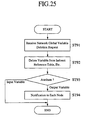
- Fig. 25 is a flowchart for describing the function (variable
deletion) of the online edit.
- Fig. 26 is a drawing showing the flowchart of the control
execution portion in the example of an online edit change.
- Fig. 27 is a drawing showing a flowchart showing an indirect
reference table rewriting process function in the example of an
online edit change.
- Fig. 28 is a drawing showing the internal structure of the
communication portion which is an essential portion of a control
apparatus equipped with a version information checking function.
- Fig. 29 is a flowchart showing the function of a selection
means.
- Fig. 30 is a drawing showing another embodiment of a control
apparatus according to the present invention.
- Fig. 31 is a drawing showing one example of a message
format used by the embodiment shown in Fig. 30.
- Fig. 32 is a flowchart showing a process function based on an
Import variable list inquiry (one batch) in the embodiment shown
in Fig. 30.
- Fig. 33 is a flowchart showing a process function based on an
Import variable list inquiry (one variable at a time) in the
embodiment shown in Fig. 30.
- Fig. 34 is a drawing showing a modification.
- Fig. 35 is a flowchart showing the function that executes the
modification shown in Fig. 34.
- Fig. 36 is a flowchart showing the essential portion of
another embodiment.
- Fig. 37 is a drawing showing one example of a data format of
a message used in another embodiment.
- Fig. 38 is a drawing for describing another embodiment.
- Fig. 39 is a drawing for describing another embodiment.
- Fig. 40 is a drawing for describing a summary of the present
embodiment that plans name solving by group units which is
another embodiment of the present invention.
- Fig. 41 is a plan view showing the interface connection of
fellow control apparatuses of the embodiment shown in Fig. 40.
- Fig. 42 is a drawing showing an example of the internal
structure of the control portion of the control apparatus used by the
embodiment shown in Fig. 40.
- Fig. 43 is a drawing showing one example of the data
structure of a group control information memory portion.
- Fig. 44 is a flowchart showing an exchange function of a
server-side control apparatus when a server joins the network or
the like.
- Fig. 45 is a flowchart showing the specific process algorithm
of the name solving request station list creation process of the
flowchart shown in Fig. 44.
- Fig. 46 is a flowchart showing the specific process algorithm
of the name solving process of the flowchart shown in Fig. 44.
- Fig. 47 is a flowchart showing the specific process algorithm
of the name solving process of the output variables shown in Fig.
46.
- Fig. 48 is a flowchart showing the specific process algorithm
of the name solving process of the input variables shown in Fig.
46.
- Fig. 49 is a flowchart showing the specific process algorithm
of the indirect reference table creation process shown in Fig. 48.
- Fig. 50 is a flowchart showing the exchange function of a
client-side control apparatus.
- Fig. 51 is a flowchart showing the specific procedure when
name solving is carried out.
- Fig. 52 is a flowchart showing an exchange function of a
client-side control apparatus when a client joins the network or the
like.
- Fig. 53 is a flowchart showing the function for replying to an
ID information request of a server-side control apparatus when a
client joins the network or the like.
- Fig. 54 is a flowchart showing a modification.
- Fig. 55 is a flowchart showing another modification.
- Fig. 56 is a flowchart showing yet another modification.
- Fig. 57 is a flowchart showing the function of a programming
apparatus.
-
PREFERRED EMBODIMENTS OF THE INVENTION
-
The present invention will now be described in greater detail
with reference to the appended drawings.
-
Fig. 1 shows a preferred embodiment of a control apparatus
according to the present invention. As shown in this drawing, the
control apparatus is equipped with a control portion 11 and a
communication portion 12. The control portion 11 executes a
ladder program, and carries out essential control of the control
apparatus, namely, a PLC 1. The communication portion 12 is
connected to a network, and possesses a function for
communicating with other control apparatuses. Specifically, the
communication portion 12 includes a communication controller 12a
which is connected to the network for carrying out transmission
and reception of data (common data exchange when stated by the
relationship with the present invention) by a prescribed
communication protocol, and a RAM 12b which temporarily stores
data at the time protocol changes are made when communication
control is carried out by the communication controller 12a, which
carries out protocol changes, and which holds information
(database) in storage when specifying the transmission and
reception destinations.
-
On the other hand, the control portion 11 includes a ROM 11a
which stores control programs sent to connected devices, control
programs used when carrying out cooperation operations with other
PLCs connected to the network, and the like; a MPU 11b which
executes programs stored in the ROM 11a; and a RAM 11c which
stores data (control data) required when executing various
processes by the MPU 11b. This hardware structure itself is
basically the same as that of the prior art.
-
In this regard, in the present invention, as shown by the
conceptual drawing in Fig. 2, respective data is defined by a
logical name (network global variable), and the user program
(object code) provided in each control apparatus (PLC) 1 acquires
shared data by specifying the logical name. In this way, it is
possible for each PLC 1 to share data without having to store the
physical address that stores corresponding data, and because the
physical address is not stored, after a recording is carried out once,
it is possible to freely change the physical address that stores the
shared data.
-
To show one example of this concept, as shown in Fig. 2, a
Switch is defined (in the case shown in the drawing, variable
name: value is defined as "Switch1") by a certain PLC 1 (1).
Then, in the case where another control apparatus (PLC 1 (3))
wants data of Switch1 of the control apparatus (PLC 1 (1)), the
user program of the control apparatus (PLC 1 (3)) specifies
"Switch1" which is a variable name, and by executing commands to
acquire such data, it is possible to acquire concrete data correlated
with Switch1. In other words, data having the same content is
defined by the same logical name, and this logical name has a sole
existence on the network. Namely, different logical names are
assigned to different data.
-
Then, in the case where there are changes in the data content,
by having a prescribed PLC rewrite such content, the content
stored in other PLCs sharing such data will also be rewritten.
-
Next, a description will be given for the specific structure for
achieving the function described above. As shown in Fig. 3, such
structure includes a link memory 15 for storing data (variable data)
logically shared via the network inside the RAM 11c, an indirect
reference table 16 used for referring to each variable data stored in
the link memory 15, and a variable database 17 correlated with the
logical names and the memory addresses (addresses of the indirect
reference table 16). Further, a detailed description of each portion
is given below.
-
On the other hand, the MPU 11b is equipped with a control
execution portion 18 for executing control operations of a PLC 1
equipped with a function for accessing the link memory 15 via the
indirect reference table 16, and a logical name adjustment portion
19 which controls the variable database 17, and which changes the
indirect reference table 16 based on information stored in the
variable database 17.
-
Next, a description of each portion will be given. First, the
link memory 15 is a memory for storing logically shared data via
the network as described above, and an example of such data
structure is shown in Fig. 4. Namely, because the same logical
name has a sole existence on the network and is shared by each of
the control apparatuses (PLCs), there is an authorization for the
process of updating and the like for the data of a certain logical
name to be executed by one specific control apparatus on the
network, and the other control apparatuses acquire data sent from
such one control apparatus. In other words, with regard to the data
of a certain logical name, the one control apparatus described
above possesses a function for carrying out updating and the like
on such data, and a function for supplying such changes to the
other control apparatuses.
-
Accordingly, as shown in the drawings, there is a self node
area which stores data related to the logical name (publicized
logical name) that possesses a function for updating itself and the
like as described above, and other node areas which store copies of
the data related to the logical name that stores data forming the
source for other control apparatuses. In the present embodiment,
the link memory 15 is divided into individual nodes in order to
improve the data transfer efficiency, but the present invention is
not limited to this arrangement.
-
Furthermore, the offset value inside the area storing the data
(variable data) of the shared same logical name (variable name) is
common to each node. Namely, in the case where variable data x
related to a certain logical name X is stored only as a prescribed
size portion from an offset value N of the self node area of node
(1) (as will be described later, a pointer related to the indirect
reference table forms N), storage in prescribed positions of other
node areas takes place in the other nodes. Then, these stored
positions are stored in a prescribed size portion area from the
offset value N of the other node areas for node (1). Namely, in the
case where the variable data publicized by the other nodes which
itself requires is stored in the other node areas of itself, storage
takes place at the same offset value as the offset value from the
head of the self node area in such publicized other nodes. In this
way, by matching the offset value of each node area with the
publicizing side and the utilization side, the various processes for
maintaining common data can be easily carried out.
-
Furthermore, with regards to the actual transmission and
reception of data, output may be carried out by the control
apparatus that possesses the supplying function described above, or
acquisition may be carried out by going and reading data from the
control apparatus that possesses data forming the source for the
other control apparatuses.
-
Further, as shown in Fig. 4, the data structure of the variable
database 17 forms a table correlated with the "logical name", the
"type", the "size", the "input/output attributes" and the "memory
address". In this regard, the "size" is the data size of information
related to the logical name, and the "input/output attributes"
specify the transmission and reception directions of data specified
by the logical name.
-
Namely, the "output" of the input/output attributes means
information related to the logical name stored in the node (PLC) is
outputted to the other nodes. Then, data related to the logical
name that forms the output of such input/output attributes is stored
in a prescribed region of the self node area of the link memory 15.
-
Further, the "input" of the input/output attributes means
information related to the logical name that will be used and the
like by the node is acquired by being sent in from the other nodes.
Then, data related to the logical name that forms the input of such
input/output attributes is stored in a prescribed region of the other
node areas of the link memory 15.
-
The "memory address" stores address information inside the
indirect reference table which stores pointers specifying the
position of the link memory 15 where the actual data related to the
logical name is stored. Further, in the present embodiment, the
offset of the indirect reference table is used. Accordingly, in order
to access the indirect reference table 16 by referring to the memory
address stored in the variable database 17, a value is formed by
adding the above-described offset to the base address of the
indirect reference table 16.
-
Further, in the present embodiment, because it is assumed
that the specified address (pointer) of the link memory address
stored in the indirect reference table 16 is expressed by 4 bytes, a
value having a multiple of 4 is stored in the memory address of the
variable database 17.
-
Now, in the example shown in the drawings, because the
memory address of the logical name "Switch1" is "0000", the data
inside the link memory 15 shown by the pointer stored in the head
(first) memory region of the indirect reference table 16 shown in
Fig. 6 forms data related to "Switch1". In the same manner,
because the memory address of the logical name "Motorl" is
"0004", the data inside the link memory 15 shown by the pointer
stored in the second memory region of the indirect reference table
16 shown in Fig. 6 forms data related to "Motorl".
-
Further, as shown in Fig. 6, the data structure of the indirect
reference table 16 stores the pointer inside the link memory 15
which stores data related to each logical name. Now, in the
present embodiment, the pointers which specify the memory areas
inside the link memory 15 are specified by 4 bytes, with the upper
3 bytes specifying the word position, and the lower 1 byte
specifying the bit position storing data forming the object inside
the word position.
-
Now, for each of these stored pointers, which logical name a
pointer is related to is specified by the correlation between the
memory address and the logical name stored in the variable
database 17 as described above. In other words, the n'th pointer
from the head of the indirect reference table 16 is recorded as a
pointer related to a prescribed logical name in advance, and this
will not change so long as the memory content (memory address) of
the variable database 17 is not changed.
-
Namely, in the case where changes are made to the memory
area of data related to a certain logical name for example, a
correspondence is made by updating the corresponding pointer
stored in the area storing pointers related to the logical names of
the indirect reference table 16. Even in this case, operations can
be completed without changing the memory contents of the variable
database 17. Accordingly, in the case where the program which
has the control apparatus carry out actual control has a need to
know information related to the logical name for sharing data,
first, the indirect reference table 16 is accessed to acquire a
pointer in accordance with the memory address stored in the
variable database 17. Next, the data indicated by such pointer is
acquired. In this way, regardless of the presence or absence of
changes to the specific memory area, it is possible for the above-described
program to acquire data and carry out operations
correctly.
-
Furthermore, in the present embodiment, the RAM 11c is
provided with an Export variable list 20, an Import variable list 21
and a Remote variable list 22 for carrying out transmission and
reception of data corresponding to the memory content of the
indirect reference table 16 described above, and the actual logical
name, and carrying out the sharing of data smoothly and reliably.
These variable lists 20 ~ 22 are created based on information
stored in the variable database 17, and the specific structures
thereof are as follows below.
-
First, the Export variable list 20 is a list of network global
variables outputted from the self node. Further, as shown in Fig.
7, the data structure thereof is formed from a table (hereafter
called "Export conversion information table") formed from the
variable name (logical name), the type and size (number of bytes)
of the variable, and the offset of the self node area (see Fig. 4)
inside the link memory 15 storing data of such variable.
-
Such table extracts the item that has "Output" in the
input/output attributes column of the variable database 5 shown in
Fig. 5, and by accessing the indirect reference table (see Fig. 6)
from the memory address column and acquiring the offset (region
storing data related to the logical name for controlling itself) of
the self node area, it is possible to create a list like that shown in
Fig. 7.
-
On the other hand, the Import variable list 21 is a list of
network global variables inputted from other nodes, and as shown
in Fig. 8, the data structure thereof is formed from a table
(hereafter called "Import conversion information table") equipped
with the variable name (logical name), the type and size (number
of bytes) of the variable, the offset of the other node area (see Fig.
4) inside the link memory 15 storing data of such variable, and
additionally a flag showing whether such variable is valid or
invalid.
-
Such table extracts the item that has "Input" in the
input/output attributes column of the variable database 5 shown in
Fig. 5, and by accessing the indirect reference table (see Fig. 6)
from the memory address column, and acquiring the offset (region
storing data sent in from other nodes) of the other node area inside
the link memory 15, it is possible to create a list like that shown in
Fig. 8.
-
Further, the Remote variable list 22 is a list which stores the
received other node variable list classified by node. As shown in
Fig. 9, the data structure thereof is formed from a table (hereafter
called "Remote conversion information table") storing the node
number and the head pointer of the Export variable list.
-
Each table information described above is carried out using a
programming apparatus (tool). Namely, as shown in Fig. 10, each
control apparatus 1 is connected in LAN2 to a network in which the
system is already operating. In such case, before a new control
apparatus (X) 1' is added to the network, a programming apparatus
3 is connected to the control apparatus (X) 1', and prescribed
data/information is downloaded into the control apparatus (X) 1'
from the programming apparatus 3.
-
Specifically, as shown in Fig. 11, first, using the
programming apparatus 3, a user creates a source program 3a by a
ladder, higher language or the like. At this time, the data shared
by a plurality of control apparatuses (1), (2), (3), ..., (X) is
defined as the same logical name by each control apparatus, and
network sharing attributes are assigned.
-
Then, a compile function 3b of the programming apparatus 3
is executed to compile the source program 3a created as described
above, and an object code 3c for having the control apparatus
execute essential controls, and a required variable database (see
Fig. 5) 3d for sharing data of the same logical name are created.
-
Next, the programming apparatus 3 downloads the created
object code 3c and variable database 3d into the control apparatus
(X) 1'. Then, these downloaded object code and variable database
are stored in a non-volatile memory of the control apparatus (X)
1'.
-
Further, although an example was described in which the
above-described programming apparatus was connected to the
control apparatus (X) 1' in the example shown in the drawing to
carry out downloading therefor, even for each of the control
apparatuses (1), (2), ... already connected to the network, before
(at the time of) connecting to the network, such control apparatuses
are connected to the programming apparatus, and prescribed
data/information is downloaded.
-
Next, a description will be given for the logical name
adjustment portion 19. The logical name adjustment portion 19
includes a function for creating the Export variable list 20 and the
Import variable list 21 based on information stored in the variable
database 17 downloaded as described above. The specific creation
process is like that mentioned in the description of the Export
variable list 20 and the Import variable list 21 described above.
-
Namely, as shown by the flowchart shown in Fig. 12, the
creation of the Export variable list 20 establishes 0 as the offset
value (ST1), and the output variable formed by accessing the
variable database 17 and outputting the input/output attribute,
namely the network global variable publicized for the other nodes
by the self node is searched (ST2).
-
Then, each time a search is carried out, an Export conversion
table storing the Export conversion information table related to
such variable is secured (ST3, ST4). Then, the variable name,
type, and size information stored in the variable database 17 is
copied in such secured table (ST5).
-
Next, offset information of the self node area that stores data
(variable data) of such variable is acquired, and the information
obtained at Step 5 and Step 6 is added to the Export variable list
(ST7). Accordingly, the first item has an offset of 0, namely,
registration is carried out from the head of the self node area.
-
Thereafter, the variable size is added to the current offset
value to calculate a new offset value (ST8), and the flowchart
returns to Step 2. Then, the processes described above are
repeatedly carried out until all the output variables have been
searched. In this way, the regions storing each variable data from
the head of the self node area is secured in an order manner
without a gap.
-
On the other hand, the creation of the Import variable list 21
is achieved by the flowchart shown in Fig. 13. Namely, the input
variable when the input/output attribute forms an input, namely the
network global variable of the other node used by the self node is
searched from the variable database 17 (ST11).
-
Then, each time a search is carried out, an Import conversion
table storing the Import conversion information table related to
such variable is secured (ST12, ST13). Then, the variable name,
type, and size information stored in the variable database 17 is
copied in such secured table (ST14). Further, the invalid flag is
set (ST15), and the information obtained at Step 14 and Step 15 is
added to the Import variable list (ST16). Thereafter, the flowchart
returns to Step 11. Then, the processes described above are
repeatedly carried out until all the input variables have been
searched.
-
Further, in addition to the function for creating both the
conversion tables described above, the logical name adjustment
portion 19 also includes a function for updating the conversion
tables described below, and the like. Namely, in the case where a
control apparatus 1 is connected to a network already in operation,
the logical name adjustment portion 19 carries out a simultaneous
broadcast of the Export variable list 20 possessed by itself, and
exchanges information of network global variables with the other
control apparatuses.
-
Namely, as shown in Fig. 14, first, the logical name
adjustment portion 19 of the side transmitting the Export variable
list carries out transmission of the Export variable list by
simultaneous broadcast (ST21). As described below, because
response signals are transmitted in from the other control
apparatuses (nodes) at the side receiving such simultaneous
broadcast, a judgment of whether or not such response signals exist
is carried out (ST22). Then, in the case where response signals
exist, the response stations issuing such response signals are
recorded (ST23).
-
Then, a check of the presence or absence of a response signal
is carried out until a time-out is made (ST24), and when a time-out
is made, table updating is completed (ST25). In this way, it is
possible for the node transmitting the Export variable list to judge
who received the Export variable list and who did not receive such
list.
-
Further, as for the transmission timing of the Export variable
list, in addition to the time where a new control apparatus is
added/connected to the network as described above, there are also
the case where the memory content of the variable database 17 is
changed in accordance with user program revisions, compile
executions or the like, and the case where the memory content of
the variable database 17 of the active control apparatus is changed
in accordance with an online edit described below. Then, in the
case where the version is updated each time a change is made, and
the Export variable list is transmitted (simultaneously
broadcasted), such version information will also be sent together
therewith. Accordingly, the nodes at the reception side include the
case where the Export variable list is received for the first time,
and the case where reception has already occurred. Further, this
version information does not necessarily have to be provided in the
present invention. Further, the synchronization method of the table
that uses the version information will be described below.
-
On the other hand, a function for executing the flowchart
shown in Fig. 15 is provided at the side of the existing other nodes
(control apparatuses) that receive the Export variable list as
described above. Namely, a judgment of whether or not the Export
variable list has been received is carried out (ST31), and in the
case where reception has occurred, a judgment of whether such
version of the Export variable list matches the version previously
received and stored is carried out (ST32).
-
Then, in the case where a match does not occur, the Export
variable list is judged to have been updated, and the stored table
(Import variable list and the like for the nodes of the reception
side) is updated (ST33). Further, even in the case where the
Export variable list is received for the first time, the version is
judged to not match, and a table updating is carried out.
-
Then, after updating the table at Step 33, and in the case
where the versions match at the branching judgment of Step 32
(updating is unnecessary), a response signal is transmitted to the
node that is the transmission source of the Export variable list, and
the process is completed (ST34).
-
Further, the logical name adjustment portion 19 includes a
function for creating the Remote variable list based on the received
Export variable list. Namely, in the process of the reception side
shown in Fig. 15, when the Export variable list transmitted in from
another node is received, this is controlled as a Remote variable
list for each node. In other words, regardless of whether or not the
received variable data is required by the node, all the information
related to the Export variable list is uptaked temporarily in the
control apparatus, and held in storage. This list is held in a non-volatile
memory. Specifically, as shown in Fig. 16, the Export
variable list sent in from node 1 is stored in the table area of node
1.
-
Then, the logical name adjustment portion 19 creates/updates
the indirect reference table 16 based on the Import variable list 21
and the Remote variable list obtained as described above. To give
a conceptual description, with the variable name (logical name)
used by the self node stored in the Import variable list 21 forming
a key, the Remote variable list 22 is searched, the matching
variable name is acquired, the pointer to the link memory 15 of the
self node storing variable data related to such variable is
calculated, and this is stored in a related memory area of the
indirect reference table 16.
-
Further, in the case where a new control apparatus joins the
network like the control apparatus (X) 1' described above, an
Export variable list request is carried out for nodes that have not
received the Export variable list. In this way, the
creation/updating of the Remote variable list 22 through the
indirect reference table 16 is carried out based on the received
Export variable list. Specifically, the flowchart shown in Fig. 17
is executed.
-
First, the Import variable list 21 is searched in order (ST41,
ST42), and the process described below is carried out for each
searched variable name (logical name). Namely, the Remote
variable list is searched with the acquired variable name as a key,
and the node address 1 ○ of the control apparatus publicizing such
variable, and the self node area offset 2 ○ inside the link memory of
such apparatus are acquired (ST43).
-
Next, the base address (head address) of the other node area
(the area for the node publicizing the variable) related to 1 ○ of the
link memory is calculated (ST44). Then, a value 3 ○ is calculated
by adding the offset 2 ○ calculated at Step 43 to the base address
(ST45). Namely, in the corresponding node area, because the
offset values of regions storing variable data of the same logical
name (variable name) are equal, the above-described calculated
value 3 ○ forms the head address of the link area storing the
variable data.
-
Next, the variable database 17 is searched based on the
variable name, and the indirect reference table position (location
storing the pointer of the variable name) is acquired (ST46).
Namely, the offset address recorded in the memory address column
shown in Fig. 5 is acquired. Then, in accordance with this
acquired offset address, the value 3 ○ (pointer showing the head
position of the region storing the variable data inside the link
memory 15) calculated at Step 45 is stored in the storage region of
the related indirect reference table. In this way, updating of the
indirect reference table can be carried out.
-
In this way, as shown in Fig. 18, for the variable database 17
shown in Fig. 5, in the example case where the storage region
inside the link memory 15 of the variable data related to the
logical name (variable name) "Switch1" is as shown in the
drawings, the address (pointer) of the head of such region is stored
in the column (offset address 0000 : head) of Switch1 of the
indirect reference table 16.
-
As described above, by having the logical name adjustment
portion 19 update the content of the indirect reference table 16 and
each of the lists 20 ~ 22 inside each node (control apparatus 1)
each time, even when the content of the variable data stored inside
the link memory 15 and the storage region of the variable data are
changed, because the storage position (offset address) of the
indirect reference table 16 related to a certain variable name
(logical name) does not change (even in the case where a change is
assumed to occur, this can be known by looking at the memory
address column of the variable database), the control execution
portion 18 can access the link memory 15 through the indirect
reference table 16, acquire desired variable data, and execute a
proper control system. Now, such function of the control
execution portion 18 is like the flowchart shown in Fig. 19.
-
Namely, after first carrying out an initialization process
(ST51), an IN refresh is carried out (ST52). In other words, the
area network global variables (variable data) stored in the other
node areas of the link memory 15 are read out. Then, the user
program (normal control) is executed (ST53), and an OUT refresh
is carried out (ST54). Namely, the network global variables
(variable data) publicized by itself are written into the self node
area of the link memory 15. Next, a peripheral I/F process is
carried out (ST55). In this way, while carrying out accessing
(reading/writing variable data) for the link memory 15, the process
for executing the user program is repeatedly carried out until the
system is shut down (ST56, ST57). Further, Fig. 20 shows a
conceptual drawing of the control apparatuses 1 and 1' at the time
the user program is executed while accessing the link memory 15
as described above.
-
Further, the actual transmission and reception of the variable
data stored in the link memory 15 is carried out between the
control apparatuses 1 (nodes) through the communication portion
12. First, to give a conceptual description, the data (variable data)
assigned to the self node area inside the link memory 15 is
transmitted to the other nodes by a simultaneous broadcast
communication method or the like, and data (variable data)
assigned to the other node areas is received from corresponding
other nodes.
-
Namely, as shown in Fig. 21, required data is transferred
between the RAM 11c of the control portion 11 side storing the
link memory, and the RAM 12b of the communication portion 12
side. In this regard, as shown in Fig. 20, the data assigned to the
self node area of the link memory 15 is copied and transferred
temporarily to the communication side RAM 12b of the
communication portion 12, and by carrying out data transfer
according to simultaneous broadcast between each control
apparatus by the fellow communication side RAM 12b (strictly,
through the communication controller 12a) thereof, data is
transmitted to the other node (control apparatus) side. Further, at
the other node side that receives this, data required by the self
node is transferred from the communication portion 12
(communication side RAM 12b) to the control portion 11 (control
side RAM 11c) based on the transfer data size calculated from the
Export variable list and the Import variable list. Furthermore, at
the communication portion 12 side, a prescribed process is carried
out based on such received data in the manner described above.
-
Further, the process function for transferring data between
the control portion 11 and the communication portion 12 inside the
control apparatus is as follows below. First, in the present
embodiment, the communication portion 12 begins a cyclic
communication service by a request from the control portion 11.
Namely, the communication portion 12 calculates and establishes
communication parameters based on the Export variable list and the
Import variable list received from the control portion 11, and
activates or subscribes to a cyclic communication service.
-
Further, the cyclic data includes valid/invalid information
indicating whether or not the data can be used by the reception
side. This valid/invalid information is established at the
transmission side. Then, when this valid/invalid information is
"valid", it is possible to judge that the communication portion of
the reception side may transfer the received cyclic data to the
control portion.
-
Furthermore, in the communication side RAM 12b, access can
be carried out both from the communication controller 12a side of
the communication portion 12, and from the control portion 11.
Accordingly, when some control is not carried out, because there
will be the situation in which the communication side RAM 12b is
accessed simultaneously from both, in order to prevent this, in the
present embodiment the control portion 11 side forms the main
object for carrying out data exchange. Namely, the control portion
11 carries out access approval/prohibition notification to the
communication portion 12. Then, the communication portion 12 is
capable of access only during the time the control portion 11
approves access to the communication side RAM. Specifically,
such control is carried out by the flowcharts shown in Fig. 22
(control portion) and Fig. 23 (communication portion).
-
First, as for the function of the control portion 11, as shown
in Fig. 22, data Reading/Writing, namely, access to the
communication side RAM 12b is carried out (ST61). Then, when
such access process is completed, the communication side is
notified of access completion (ST62). This access completion
notice forms an access approval notice for the communication
portion 12.
-
Then, a normal controller process (user program execution) is
carried out (ST63). Further, in the case where there arises a need
to access the communication side RAM 12b again, an access
request notice is notified to the communication portion 12 (ST64).
As will be described below, because the communication portion 12
that received this notice will send back an access approval notice,
a judgment of whether or not the control portion 11 has received
the access approval notice from the communication portion 12 is
carried out (ST65), and when an approval notice is received, the
access status is cleared (ST66), the flowchart returns to Step 61,
and the control portion 11 accesses the communication side RAM
12b.
-
On the other hand, as for the function of the communication
portion 12, as shown in Fig. 23, first, a judgment of whether or not
an access completion notice has been sent in from the control
portion 11 is carried out (ST71). Then, when such access
completion notice has been received, the communication side RAM
12b is accessed (to Read/Write data) (ST72). Next, a judgment of
whether or not an access request notice has been sent in from the
communication portion 12 is carried out (ST73). Then, in the case
where such notice has not been sent in, because the communication
portion 12 still has the right to access the communication side
RAM 12b, access is carried out as needed.
-
On the other hand, when an access request notice has been
received, the accessing of the communication side RAM 12b is
terminated, and an access approval notice is sent back to the
control portion 11 (ST74). At this time, in the communication
portion 12, because the simultaneity of the node units of the
received data is secured, when an access request notice is received
during the transfer of one node portion, an access approval notice
is sent back after the transfer of such one node portion is
completed. Further, after the interruption by the notice at Step 74,
when an access completion notice is received again from the
control portion 11, transfer is started to the communication side
RAM 12b of the next node after the node having the above-described
interruption.
-
With the above-described embodiment as a base, it is possible
to further add the functions described below. First, an online edit
function is provided as a first additional function. Namely, a
function is provided to interpret an online edit request sent in from
the programming apparatus, add or delete a logical name in the
variable database 17, and change the indirect reference table 16
inside the self control apparatus in accordance with the changed
content of the variable database 17. A description of each process
is given below.
-
First, the process function for adding network global
variables in the online edit is like the flowchart shown in Fig. 24.
Namely, first, a network global variable addition request is
received from a connected programming apparatus (ST81). Then,
first, a judgment of whether the attribute of the variable data of the
added logical name is an input variable or an output variable is
carried out (ST82).
-
Then, in the case of an input variable, a judgment of whether
the variable is a variable (previously publicized variable) that has
already been publicized by another node is carried out (ST83). In
the case where the variable has not been publicized (unpublicized
variable), because it is not possible to acquire and use data of the
variable at the current point in time, an Import variable table
related to the variable is created, and upon setting the valid/invalid
flag at invalid, the variable is added to the Import variable list
(ST84). Further, the flag related to this variable is switched to
valid when another node publicizes such network global variable.
-
Then, information related to the variable is added to the
indirect reference table based on the memory address of the
variable database 17 (ST85). On the other hand, in the case where
the input variable of the processing object has already been
publicized by another node, the variable is added to the indirect
reference table based on the variable database (ST85).
-
On the other hand, in the case where the attribute is an output
variable, the flowchart proceeds to Step 86 at the branching
judgment of Step 82, and a judgment of whether or not there exists
an open region in the self node area of the link memory 15 is
carried out (ST86). Namely, a judgment of whether or not there
exists memory space of the data size related to such variable stored
in the variable database 17 is carried out. Then, in the case where
there is no space, because it is not possible to make an addition, an
error process is carried out. Further, in the case where there is
space, a region (data size portion) for storing such variable data is
secured inside the self node area (ST87). Then, the offset (head
address) of the secured region is stored in a related table of the
Export variable table, and the offset (head address) of the secured
region is written into the indirect reference table (ST88). Further,
the created Export variable table is added to the Export variable
list. Thereafter, only the added variable information is notified to
each node by transmission of the Export variable table (ST89).
-
Further, the deletion process function of the online edit is
like the flowchart shown in Fig. 25. Namely, first, a network
global variable deletion request is received from a connected
programming apparatus (ST91). Then, variable information related
to the logical name is deleted from the indirect reference table and
the like (ST92). Next, a judgment of whether the attribute of the
deleted variable data is an input variable or an output variable is
carried out (ST93). Then, in the case where the attribute is an
input variable, because there will be no effect for the other nodes,
the process is terminated as is.
-
Further, in the case of an output variable, because there will
be an effect on other nodes using such variable data, the deleted
variable name (logical name) is notified to each node (ST94).
Further, at each node that receives this deleted variable name
notice, the valid/invalid flag related to such variable inside the
Import variable list is set at invalid.
-
Furthermore, the changes of the data size, attribute and the
like of the network global variables in the online edit can be
carried out after the above-described deletion process by once
again carrying out the addition process.
-
Further, with the above-described online edit function
forming a precondition, a second additional function can be
constructed in which the indirect reference table is provided with
two banks, and by appropriately switching between a used bank and
an unused bank, it is possible to keep control execution
interruptions at a minimum.
-
Namely, the content of the used bank is copied in the unused
bank in advance, and in the case where the content of the variable
database 17 is changed, first, the unused bank is updated, and after
that the used bank is switched to the unused bank when the control
execution portion 18 is not referring to the bank being used. In
this way, because the used bank does not change even during
updating of the indirect reference table for the used bank, it is
possible for the control execution portion 18 to carry out processes
by referring to the arranged bank being used during such updating
operation. Accordingly, the control execution interruption period
can be shortened as much as possible. Now, the functions of the
control portion for executing such process functions is like the
flowcharts shown in Figs. 26 and 27.
-
Namely, as shown in Fig. 26, after first carrying out an
initialization process (ST101), the control execution portion 18
carries out an IN refresh (ST102). In short, the area network
global variables (variable data) stored in the other node areas of
the link memory 15 are read out. This accessing of the link
memory 15 is carried out by specifying the address based on the
indirect reference table of the used bank.
-
Then, the user program (normal control) is executed (ST103),
and an OUT refresh is carried out (ST104). Namely, the network
global variables (variable data) publicized by itself are written into
the self node area of the link memory 15. Naturally, this is also
carried out by specifying the storage region of the link area based
on the pointer stored in the indirect reference table of the used
bank. Next, a peripheral I/F process is carried out (ST105). The
interval from Step 102 to Step 105 is the period over which the
control execution portion 18 is referring to the bank being used.
-
Thereafter, a standby is carried out for only the cycle time
(ST106). The interval of this cycle time is the period over which
the control execution portion 18 is not referring to the used bank.
In this way, while carrying out accessing (reading/writing variable
data) for the link memory 15, the process for executing the user
program is repeatedly carried out until the system is shut down
(ST107, ST108). At this time, a standby is carried out for a
prescribed time each time one series of processes is finished.
-
On the other hand, the process function for rewriting the
indirect reference table is like the flowchart shown in Fig. 27,
wherein, first, the content of the indirect reference table of the
used bank is copied in the unused bank (ST111). Next, the indirect
reference table copied in the unused bank is updated (ST112).
Then, a judgment of whether or not the control execution portion
18 is referring to the link list is carried out (ST113). Namely, a
judgment of whether or not Step 102 through Step 105 are being
executed is carried out. Then in the case where such reference is
not being carried out (during the standby of Step 106), the process
for switching the used indirect reference table with the copied
indirect reference table is completed (ST114).
-
Further, a data control function which uses version
information is provided as a third additional function. Namely, in
the embodiment described above, only the updated version variable
table is recorded, but the present invention is not limited to this,
and version information may be added to both the variable database
and the transmission data, and the changed content of the variable
database may be sent to each node by simultaneous broadcast. In
this way, a judgment of whether or not the version information
added to the variable database and the version information related
to data transmitted thereafter matches that of the variable database
can be carried out, and it is possible to carry out an updating
process in which only matching items are recognized as proper
data.
-
In this way, by transmitting the variable database to each
node in advance so that each node will know the version, it is
possible to insure that all the nodes connected to the network will
use the same version variable data. Now, as for the specific
structure for achieving such process function, for example, the
structure of the communication portion 12 may be constructed as
shown in Fig. 28.
-
Namely, the communication portion 12 is equipped with a
reception portion 25 which receives data sent in from the other
nodes, a selection means 26 which receives the data (messages)
received by the reception portion 25 and carries out a judgment of
whether or not the version is correct, a selection information
holding means 27 which holds the version information and the node
address that should carry out reception which form a
reference/dictionary at the time the judgment is carried out by the
selection means 26, a data holding portion 28 which holds data
judged to be true data (matching version or the like) by the
selection means 26, and a notification means 29 which notifies the
transmission source node that the version does not match in the
case where data is judged to not be true data. Further, as for the
function of itself as a transmission side, the communication portion
12 is equipped with a data holding portion 30 which temporarily
stores information related to the variable publicized by itself, and
a transmission portion 31 which transmits the data stored in the
data holding portion 30 to the other nodes.
-
As for the version information and the like stored/established
in the selection information holding means 27, it is possible to
receive and record version information of the variable database
sent from the node that is the publicizing source of the variable
name (variable data). Now, as shown in Fig. 28, the frame format
of the message actually sent in records the version information of
the data between the header which stores information of the
transmission source, address and the like, and the data forming the
actual transmission content. Further, which node data is sent in
from is understood from the transmission source information of the
header.
-
Further, the function of the selection means 26 is like the
flowchart shown in Fig. 29. Namely, when a message is received
through the reception portion 25 (ST121), the established version
information and node address that should carry out reception stored
in the selection information holding means 27 are compared with
the version and the like of the received data, and a judgment of
whether or not there is a match with the established information is
carried out (ST122). Then, in the case where there is a match, the
received message is transferred to the data holding portion 28
(ST123). Further, this transferred message stored in the data
holding portion 28 sends data of a required location to the control
portion 11 side, and based on this, required processes such as
updating the variable list, the indirect reference table and data of
the list memory and the like are carried out. On the other hand, in
the case where the version and the like do not match, the
transmission source node is notified of such nonmatch through the
notification means 29 (ST124). This notification may be carried
out simply by notifying that the version does not match, or the
version information stored in the selection information holding
means 27 may be sent together with the notice. The transmission
source node that receives this resends data (Export variable list) of
the correct version, and once again sends the current correct
version information (variable database) that should be stored to the
selection information holding means 27.
-
Further, as another additional function, it is possible to add a
function (plug-in function) that automatically starts communication
with existing control apparatuses when a new control apparatus is
added, exchanges each variable list and the like, and creates a state
which makes it possible to share logical data.
-
On the other hand, in the embodiment described above, all of
the Export variable list sent in from each of the other nodes is
temporarily uptaked as a Remote variable list inside the control
apparatus, and is thereafter collated with an Import variable list to
create an indirect reference table, but the present invention is not
limited to this, for example, each time an Export variable list is
received from another node, this can be compared with the Import
variable list of the self node, and only required information may be
uptaked. In this way, it is possible to greatly reduce the memory
capacity for storing the Remote variable list. Accordingly,
application to small-scale control apparatuses and other nodes
becomes possible
-
Furthermore, each node inquires about the variable name
required by the self node, and this makes it possible to acquire
information related to such variable name from the publicizing
node. In this way, because a large-scale Remote variable table
becomes unnecessary, it becomes possible to further reduce the
memory capacity, and this makes it possible to develop a low-cost
device.
-
Specifically, as shown in Fig. 30, a plurality of nodes
(control apparatuses 1) are connected to a network, and each of
these possesses an Export variable list 20 and an Import variable
list 21 required by the self node. Then, as is clear from a
comparison of Fig. 30 with Fig. 3 and the like, each node is also
equipped with an indirect reference table 16 and a link memory 15,
but does not possess a Remote variable table. Further, Fig. 30
shows one portion of the internal structure of the RAM of each
node, and required functions are stored in a MPU and a ROM in the
same manner as that of the embodiment shown in Fig. 3 and the
like.
-
In such structure, each node transmits the variables recorded
in the Import variable list 21 to all the nodes by simultaneous
broadcast (In the example shown in the drawing, an example in
which transmission from node (1) is carried out is shown (1 ○ of
Fig. 30) ). The nodes that receive this variable name inquiry frame
carry out a search of whether or not a related variable exists in the
Export variable list of the self node (2 ○ of Fig. 30). Then, when
the search result indicates that a related variable exists, the frame
that records the node address of itself and the variable address is
sent as a reply to the node (node (1) in the example shown in Fig.
30) that transmitted the variable name inquiry frame (3 ○ of Fig.
30).
-
In this way, because each node can acquire information of
variables used by itself, the indirect reference table is created
based on such frame. Further, because the process for creating the
indirect reference table is the same as that of the embodiment
described above, a detailed description thereof is omitted.
-
Now, to give one example of a frame format of the inquiry
frame of the variable name described above, as shown in Fig. 31(a)
for example, it is possible to transmit all the Import variable list in
one batch. In this case, there are many instances where a plurality
of frames from a plurality of nodes form replies. Further, as
shown in Fig. 30(b), it is possible to transmit one frame at a time
for each variable. In this case, as a matter of course, there
becomes one reply frame. Now, Fig. 31(c) shows one example of
the frame format of the reply frame.
-
Then, the function in the case where the entire list of the
Import variable list is inquired in one batch is like the flowchart
shown in Fig. 32. Namely, first, a variable inquiry frame is
transmitted to all nodes (ST131). Next, the node waits for
reception while checking a timer, and a judgment of whether or not
there is a reply for such frame is carried out (ST132, ST134), and
when a reply is received, an indirect reference table is created
based on the content of such reply (ST133). Then, when no reply
comes within a prescribed time, a reply waiting time-out is carried
out, and the creation of the indirect reference table is completed.
Further, in the case where it is not possible to create an indirect
reference table related to the variable name present in the Import
variable list, the node that makes such variable name the output
variable is judged to not exist in the system at the present step.
Accordingly, the valid/invalid flag of the Import variable list
becomes invalid.
-
Further, the function in the case where the Import variable
list is inquired one variable at a time is like the flowchart shown in
Fig. 33. Namely, a variable inquiry frame (of one variable portion)
is transmitted to all nodes (ST141). Next, the node waits for
reception while checking a timer, and a judgment of whether or not
there is a reply for such frame is carried out (ST142, ST144), and
when a reply is received, an indirect reference table is created
based on the content of such reply (ST143). Now, when no reply
comes within a prescribed time, a reply waiting time-out for such
variable is carried out, and an indirect reference table for such
variable is not created. Namely, the node that makes such variable
the output variable is judged to not exist at the present point in
time. Then, the process described above is repeatedly carried out
for all the variables, and when reception occurs for all the
variables, the process is completed (ST145).
-
In the present embodiment, in addition to the merit that a
memory capacity required for the Remote variable list becomes
unnecessary, there is also the effect that traffic is greatly reduced.
Namely, for example, when assuming the case where a new node is
added, such added node transmits a variable name inquiry related
to the variable (variable stored in the Import variable list) required
by itself by simultaneous broadcast in a prescribed frame format.
Then, because only the node that has a related variable will
transmit a reply frame related to such variable, there is no need for
all the nodes to transmit all their data, and this greatly reduces
traffic.
-
Furthermore, in the case where there exists the same variable
name for different data (i.e., a double variable), the present
embodiment makes it possible to detect such fact. Namely, in the
present embodiment, the sole existence of the same logical name on
the network forms a precondition, and there exists only one node (0
in some cases) that makes the same logical name an output
variable. In this regard, in accordance with the present
embodiment, when there exist a plurality of nodes which make the
inquired variable name an output variable, each of such nodes that
received the inquiry frame transmitted by simultaneous broadcast
will transmit a reply frame, and then the node that made the
inquiry will receive a plurality of reply frames for the same
variable inquiry. In accordance with this, it is possible to detect
the double definition of the variable.
-
As shown in Fig. 34, in place of the Export variable list
shown in Fig. 7, a "used/unused" area is further added to the
variable list of Fig. 7. This "used/unused" area is a flag showing
whether or not the variable data of the variable name is
utilized/used by other nodes, wherein "1" is set for the case where
the data is used, and "0" is set for the case where the data is
unused.
-
In this way, in the case where data link communication is
carried out, in the basic embodiments described from Fig. 1, all the
variables shown by the Export variable list are transmitted
cyclically, but in the present method, by checking the
"used/unused" area, it is possible to carry out transmission only
for "used" variables without having to transmit all data. In this
way, it is possible to suppress the increase in network traffic due
to the transmission of useless data not used by anyone.
-
Now, the setting of the flag for such area can be easily
achieved in the case where the inquiry is carried out based on the
Import variable list in the manner of the present embodiment.
Namely, the initial value of the "used/unused" area is set at 0 in
advance. Then, in the case where the variable of the inquiry exists
when a search of the Export variable list is carried out, by setting
"1" in the "used/unused" area related to such variable to show that
the variable is being used, it is possible to achieve such flag
setting.
-
As for a flowchart of the processing portion for achieving
such function, it is possible to use the flowchart shown in Fig. 35.
Namely, when an inquiry frame of the Import variable list is
received (ST161), the Export variable list is searched, and a
confirmation of whether or not the variable of the inquiry exists is
carried out (ST162, ST163). Then, if such variable does not exist,
the process is terminated without sending back a reply. Further, if
such variable exists, a reply is sent back in the form of a reply
frame recording the address of the self node and the address of the
related variable (ST164). Then, 1 is set in the "used/unused" area
(ST165). Further, the flowchart (from ST161 to ST164) without
the provision of this Step 165 forms a flowchart for achieving a
normal process function.
-
Moreover, it is also possible to use a combination of the
embodiment (Method 1 ○) of the basic functions from Fig. I onwards
described above, and the embodiment (Method 2 ○) shown from Fig.
30 onwards. Namely, in the embodiment from Fig. 1 onwards, the
nodes have sufficient memory capacity, and when an indirect
reference table is simultaneously created by a plurality of nodes at
the setup time or the like, because this can be carried out by only
transmitting the Export list, there is good efficiency. Further, for
a node that carries out Import of a major portion of area of the
system, there is good efficiency for the case where an Export list is
received from all nodes.
-
On the other hand, in the case where a new node is added
when a data link is already operating in the system, there is good
efficiency for the embodiment of Fig. 30 onwards. Further,
because only required variables are received, there is good
efficiency even for nodes that have a small Import variable list. In
this way, because both embodiments have respective merits, by
combining these, a synergistic effect of such merits can be
expected. Now, the method of such combination is carried out by
the rules shown below. In this regard, the process flowchart for
achieving such rules is like that shown in Fig. 36.
- 1 ○ Before beginning the creation of the indirect reference table,
5 each node transmits the Export list of the self node (Method 1 ○) ;
- 2 ○ When the memory capacity of the Remote table is small, each
node nullifies the received Export list;
- 3 ○ At this step, when the indirect reference table has been created,
the process is completed at this point ;
- 4 ○ In the case where the indirect reference table is incomplete
(there is still an unsolved Import variable list), an indirect
reference table is created by an inquiry according to Method 2 ○ ;
- 5 ○ In the case where the indirect reference table is incomplete even
when the process of 4 ○ is carried out, the node that possesses such
variable is judged to not have been set up yet, and a data link
operation is begun ;
- 6 ○ When a new node is added while the data link is operating,
because an Export list is sent in from such node, this is collated
with the Import variable list, and when the variable exists, an
indirect reference table is created ;
- 7 ○ When a node is already set up at the time a data link is operating
on the network (midway joining from the viewpoint of the other
nodes), first, the Export list of the self node is transmitted in the
same manner as 1 ○ ;
- 8 ○ Because Export lists are not sent in from the other nodes, the
size of the Import list is checked, and when this size is larger than
a prescribed value (e.g., 1,000 variables), Method 1 ○ is carried out
(the transmission of an Export list is required for all nodes), but
when this size is smaller than the prescribed value, and an indirect
reference table is created by Method 2 ○.
-
-
Incidentally, in each embodiment and modification
(additional function) described above, communication between
control apparatuses connected to the network is carried out merely
by defining the logical name shared between the plurality of
control apparatuses connected to the network, and even in the case
where the state of the communicating control apparatuses change
(addition to or removal from the network, content changes due to
recompiling, etc.), it is possible to solve the correspondence of the
shared logical name and the address of the link memory without
interrupting control.
-
Now, in order to plan such solution, the link memory 15 and
the indirect reference table 16 are provided, but the present
invention does not necessarily have to be provided with such
structure. Then, in the case where such structure is not provided,
at least the logical name and the data thereof is stored inside the
message received by the control apparatus as shown in Fig. 37, and
the storage addresses of the network global variables are specified
one communication at a time by the variable database, and data
updating is carried out (see Fig. 38). In this case, a request to
rewrite a plurality of network global variables may be included
inside one message.
-
Further, in each embodiment described above, a link memory
for storing variable data or information such as various variable
lists and the like is stored in a non-volatile memory. Specifically,
storage is carried out in a prescribed area of the RAM 11c inside
the control portion 11. However, the present invention is not
limited to this, and as shown in Fig. 39 for example, a memory
portion 13 may be provided separate from the control portion 11
and the communication portion 12, and data may be stored inside
this memory portion 13. Now, this memory portion 13 may of
course be divided into a plurality.
-
Further, in each of the embodiments and the like described
above, descriptions were given for apparatuses that possess both
input and output functions, but the present invention is not limited
to this, and application can be made to a control apparatus (node)
of only input variables, or a control apparatus (node) of only
output variables. In the case of each of such control apparatuses,
this can be easily achieved by eliminating the function that is not
used from the functions described in the embodiments described
above. Namely, for example, in the case of a control apparatus of
only input variables, the Export variable list becomes unnecessary,
and a correspondence is possible by eliminating the function for
creating the Export variable list as a function of the logical name
adjustment portion 19.
-
Furthermore, each structure described above is not limited to
data communication between control apparatuses, and application
can also be made to a multi-MPU structure. Namely, although
omitted from the drawings, a multiprocessor system (multi-MPU)
in which each MPU possesses an occupied local memory, wherein
these are connected by a serial pass or parallel pass, forms a
precondition. Now, this can be achieved by providing a data
transfer process portion which periodically carries out data
exchange between each local memory, an indirect reference table
used for accessing data stored inside these local memories, a
control execution portion which possesses a function for accessing
data through the indirect reference table, and a logical name
adjustment portion which controls a corresponding table of logical
names and local memory addresses, and changes the indirect
reference table based on such information. In this case, the local
memory corresponds to the link memory of the embodiments
described above, and the data which is exchanged periodically
forms the variable data in the embodiments described above.
-
Then, based on each processing portion and table and the
like, it is possible to make data common by creating an appropriate
variable link and the like. Further, because the specific process
function can be achieved by a process the same as that for sharing
data between the control apparatuses described above, a detailed
description thereof is omitted.
-
Fig. 40 shows another embodiment of the present invention.
In each embodiment described above, the control apparatuses are
connected by network global variables, and because fellow control
apparatuses automatically carry out name solving of such network
global variables, by using the respective programming tool stored
in each control apparatus, it is possible to easily integrate the
developed control programs as a system. In this way, an effect is
created making it possible to support incremental development or
simultaneous parallel development by a plurality of people. This
control apparatus automatically exchanges variable information
with fellow control apparatuses, possesses a structure for assigning
a batch of variables to memory before data transfer, and
automatically carries out name solving. Now, this name solving is
executed at the time the power source is switched ON or at the time
a control apparatus joins the network.
-
In contrast with the planning of name solving by each
variable unit in this way, in the present embodiment, the network
global variables are grouped, and the version and ID are controlled
by such group unit.
-
Namely, when name solving is required such as at the time
the power source is switched ON or at the time of network joining
or the like, the versions (ID) of the fellow group possessed by each
control apparatus are compared, and when they are the same, it is
possible to judge that name solving has been carried out once
before, and because no changes of the content are considered to
occur thereafter, a new name solving is not carried out for the
network global variables belonging to such group.
-
By providing such structure, it is possible to reduce the
number of processes for actually carrying out name solving, and it
is possible to greatly shorten the time up to the start of the
program execution of the control apparatus. In particular, in many
cases, because name solving takes place at the time of site
adjustment, debugging and the like, by executing only a version
check at the time the power source of the control apparatus is
switched ON during actual system operation, or at the time a
control apparatus is added to or removed from the network, it is
possible to reduce the network load and minimize effects on the
system. Namely, for example, in the case where a control
apparatus that is cut off once due to a network disconnection or
bad contact joins the network again, name solving is carried out
every time such situation occurs in each embodiment described
above, but in the present embodiment, restoration is possible by
executing only a version check, and for this reason the present
embodiment is preferred. Further, in the case where the version
does not match, name solving of the network global variables
belonging to such group is carried out, and the specific process
thereof can be executed by the method described in each
embodiment described above.
-
Further, the version and ID of the group described above is
updated in the case where the memory content of the variable
database 17 is changed due to a user program revision or a
compiling execution or the like, or every time the memory content
of the variable database 17 of an operating control apparatus is
changed due to an online edit.
-
Further, when the network global variables are grouped, the
variables are preferably categorized for a separate purpose. By
carrying out this kind of grouping, because it can be assumed that
the control apparatus that uses data of the same group will carry
out coordination/synchronization control and the like, it becomes
possible to easily know the relationship between fellow control
apparatuses. For example, in the example shown in Fig. 40, it is
understood that the network global variables belonging to group A
are shared by the control apparatus (1) and the control apparatus
(2), and the network global variables belonging to group B are
shared by the control apparatus (2) and the control apparatus (3).
-
Furthermore, the possessors of the group of network global
variables are made clear. Namely, changes to network global
variables belonging to one group are carried out by one control
apparatus 1 (server) that is the possessor existing on the network,
and the other sharing control apparatuses 1 (clients) receive data
transmitted from the possessor control apparatus. In this way, the
group (meaning a bundle of data, not individual data) can be
regarded as an external interface of the control apparatus 1
possessing such group, and it becomes easy to appropriate the one-time
developed function module (including the control apparatus,
the control software and the control object hardware) as a standard
module.
-
In the example shown in Fig. 41, a respective external
interface In is connected to each control apparatus 1. Then, the
one interface I2 of the control apparatus (1) forms group A made up
of a plurality of network global variables, and this group A is also
utilized by the control apparatus (2). Further, the specification of
a variable is carried out by the group name and the network
variable name. In this way, when the same network variable name
is not inside the group, the network global variable specified by
the group name and the network variable name has a sole existence
on the network.
-
As described above, by having one control apparatus 1
possess the group, and by considering the group as an external
interface of such control apparatus, apparatus development by
combination of the standard module and construction of a plant
line become easy. Further, input variables or output variables or
both of such variables for the control apparatus 1 that possesses
the interface can be included in the interface. Further, when the
group/interface concept is expressed by language, a correspondence
of the structural body or class may be applied to the interface.
Then, there is the concept of a class (model) and an instance in the
interface.
-
Next, as for the specific structure of the control apparatus 1
for carrying out the name solving by group units described above,
it is possible to use the structure shown in Fig. 42. As is clear
from this drawing, in the present embodiment, the embodiment
shown in Fig. 3 is used as a base, and a group control information
memory portion 35 is further provided inside the RAM 11c.
-
This group control information memory portion 35 is a
memory portion that groups and holds the logical names (network
global variables) of data shared between the plurality of nodes
(control apparatuses) connected to the network. As shown in Fig.
43, the internal structure (data structure) of this group control
information memory portion 35 is provided with the group name,
the ID (or version) of such group, a server/client attribute which
specifies whether a control apparatus forms a server having
possession rights for such group or forms a client at the utilization
side, and an Export list and an Import list which store information
related to the variable names belonging to such group. Because
these Export list and Import list are the same as those of the
embodiment shown in Fig. 7 and Fig. 8, a detailed description
thereof is omitted. Further, because the other structures and
operational effects are the same as those of the embodiments
described above, the same reference characters are assigned to
corresponding members, and a detailed description of each function
is omitted.
-
Next, a description will be given for the algorithm that
carries out name solving in a system constructed by providing the
network with a plurality of the control apparatuses 1 described
above. This process is basically executed by the logical name
adjustment portion 19.
-
Although a description will be repeated, in the case where the
server-side control apparatus and the client-side control
apparatuses possess the same group name, the essential portion of
the present embodiment collates each other's ID. Then, when the
IDs are the same, name solving is judged to have been carried out
once, and a new name solving for the network global variables
belonging to such group is skipped. Further, in the case where the
IDs are different, a new name solving is actually carried out for
the network global variables.
-
Namely, in the case where the server-side control apparatus 1
joins the network, or the server-side group changes, the server-side
control apparatus 1 transmits the pair of the group name and the ID
on the network by simultaneous broadcast. In this way, because
the other control apparatuses 1 connected to the network will
receive this simultaneously broadcasted data, the client-side
control apparatus 1 accesses the group control information memory
portion 35, and searches the group name transmitted in from the
server. Then, when the same group name is present, the IDs are
then collated.
-
At this time, in the case where the stored ID and the received
ID are the same, the response "there is no name solving request" is
sent back to the server-side control apparatus 1. Further, in the
case where the IDs are different, the response "there is a name
solving request" is sent back to the server-side control apparatus 1.
-
The server-side control apparatus that receives the responses
described above creates a "name solving request station list" from
only the nodes that sent in the "there is a name solving request"
response, and name solving is individually carried out between the
nodes (control apparatuses) present in such "name solving request
station list".
-
On the other hand, in the case where a client-side control
apparatus 1 joins the network, or the client-side group changes, the
client-side control apparatus 1 simultaneously broadcasts the group
name of the group used by itself, and makes a request by
transmitting the pair of the group name and the ID to the server-side
control apparatus 1. The prescribed server-side control
apparatus 1 that receives this replies by sending back the pair of
the group name and the ID possessing the same group name stored
in the group control information memory portion 35.
-
Next, based on the pair of the group name and the ID sent in
from the server-side control apparatus, the client-side control
apparatus 1 accesses the group control information memory portion
35, and searches the group name transmitted in from the server.
Then, when the same group name is present, the IDs are then
collated, and in the case where the stored ID and the received ID
are the same, the response "there is no name solving request" is
sent back to the server-side control apparatus 1. Further, in the
case where the IDs are different, the response "there is a name
solving request" is sent back to the server-side control apparatus 1.
-
Then, the server-side control apparatus that receives the
responses described above creates a "name solving request station
list" from only the nodes that sent in the "there is a name solving
request" response, and name solving is individually carried out
between the nodes (control apparatuses) present in such "name
solving request station list". Accordingly, in either case, the
control apparatuses that possess a group having the same name skip
the actual process of name solving of the network global variables.
-
Next, the specific functions of each control apparatus for
carrying out all the processes described above will be described
separately for the server side and the client side respectively for
the case where a server-side control apparatus joins the network or
the like, and there arises the possibility of carrying out name
solving, and the case where a client-side control apparatus joins
the network or the like, and there arises the possibility of carrying
out name solving.
-
The control apparatus having "server" in the server/client
attribute column of the group control information memory portion
35 forms the server for the group. Now, this server is equipped
with an exchange function which sets the same group as an
interface, and exchanges ID information with other control
apparatuses having "client" in the server/client attribute, and an
exchange function which exchanges the variable database
information of the network global variables with the other control
apparatuses only when there is a request from the client side.
Now, the two functions are provided in the logical name adjustment
portion 19.
-
The control apparatus having "client" in the server/client
attribute column of the group control information memory portion
35 forms the client for the group. The control apparatus having a
client attribute is equipped with an ID information reception
function which receives ID information transmitted in from other
control apparatuses possessing the same group name having a
server attribute, a request function which makes a request for name
solving of the network global variables to the server-side control
apparatus in the case where such ID and the ID controlled by the
self control apparatus are collated and found to be different, and an
exchange function which thereafter exchanges variable database
information with the server-side control apparatus. Now, each of
these functions are also provided in the logical name adjustment
portion 19.
-
Now, the process at the time the server-side control apparatus
joins the network or at the time the server-side group is changed is
carried out by the exchange function formed from the flowchart
shown in Fig. 44.
-
A judgment of whether or not a control apparatus has joined
the network is carried out, and when a control apparatus has
joined, the process described below is carried out by group units
for all the groups held in the group control information memory
portion 35 (ST171 ∼ ST173).
-
First, the server/client attribute is recognized, and a
judgment of whether or not there is a server attribute is carried out
(ST174). Then, in the case of a client attribute, because there is
no need for the process of the server side, the flowchart returns to
Step 172 and proceeds to the process for the next group.
-
On the other hand, in the case of a server attribute group, a
process for creating a name solving request station list is carried
out (ST175). Namely, a required series of processes are carried
out in order to create a "name solving request station list" which
lists the nodes requiring name solving of the global network
variables described above, specifically, the flowchart shown in Fig.
45 is carried out.
-
Namely, first, this name solving request station list creation
process transmits the pair of the group name and the ID of the
group forming the processing object to the other nodes (the other
control apparatuses connected to the network) by simultaneous
broadcast (ST180). Then, as described later below, because the
control apparatuses that form clients which use the received group
will reply by sending back "there is a/no name solving request"
responses, a judgment of whether or not there is such response
(reply) is carried out (ST181), and in the case where there is a
response, a judgment of the content thereof is carried out (ST182),
and only in the case where there is a name solving request, the
network address of the reply station (control apparatus) that replies
by sending a response is recorded, and a name solving request
station list is created (ST183). Further, the name solving request
station list is a table which lists the network addresses of reply
stations (control apparatuses that require name solving).
-
Accordingly, a No at the branching judgment of Step 182
occurs in the case where the response sent in from the control
apparatus indicates that there is no name solving request (the IDs
match), and because the network address of the reply station
(client-side control apparatus) is not recorded in such case, the
name solving that is executed thereafter is also not carried out.
Namely, name solving is skipped.
-
Further, when there is no reply from the other control
apparatuses after a prescribed time has passed since the
simultaneous broadcast, a time-out is carried out and the name
solving request station list creation process is terminated, and then
operations proceed to the next process.
-
When the name solving request station list is created by
carrying out the name solving request station list creation process
described above, a name solving process (ST178) is carried out
repeatedly (ST176 ~ ST178) in accordance with such list. Then,
when name solving has been carried out between all control
apparatuses recorded in the list, a Yes is made at the branching
judgment of Step 177, and the flowchart returns to Step 172 and
proceeds to the process for the next group.
-
Further, the name solving process of Step 178 is specifically
carried out like the flowchart shown in Fig. 46. Namely, because
the network addresses of the control apparatuses that require name
solving are listed in the name solving request station list, the
process is carried out in an ordered manner (ST191, ST192).
Namely, first, name solving is carried out for the output variables
(ST193), and then name solving of the input variables is carried
out (ST194). Further, the processes for the output variables and
the input variables may also of course be carried out in reverse.
-
Then, as shown in Fig. 47, in the name solving process of the
output variables, first, the server-side logical name adjustment
portion 19 specifies the related group name, and transmits an
Export variable list (ST200). The destinations of this-transmission
are the control apparatuses recorded in the name solving request
station list for the processing object group. Namely, the exchange
of variable database information is carried out by one-to-one peer-to-peer
communication between the control apparatus and the
control apparatuses in the name solving request station list.
-
As described later, because the other control apparatuses
(nodes) of the reception-side that receive the transmission of the
Export variable list will transmit reply signals, a judgment of
whether or not there is such a reply signal is carried out (ST201).
Then, in the case where there is such reply signal, a judgment of
whether or not such reply is a normal response is carried out
(ST202), and table updating is completed (ST203). In this way, it
is possible for the control apparatus that transmits the Export
variable list to judge who receives the Export variable list, and
who does not receive the Export variable list. Then, the check of
the presence or absence of the reception of a reply signal is
executed until a time-out is carried out (ST204), and when a time-out
is carried out, the name solving process of the output variables
is terminated. Further, the process is also terminated in the case
where the reply signal is not a normal response.
-
Further, as shown in Fig. 48, in the name solving of the input
variables, first, the server-side logical name adjustment portion 19
specifies the related group name, and creates and transmits a frame
inquiring about the Export variable list held by the fellow control
apparatuses (ST210). Because a corresponding Export variable list
will be sent in from the above-described fellow control apparatuses
as a reply to this inquiry, a judgment of whether or not there is
such reply is carried out (ST211). Then, in the case where there is
such reply, the fact that there is no error is confirmed (ST212), and
an indirect reference table is created (ST213). Then, the check of
the presence or absence of reception of a reply signal is executed
until a time-out is carried out (ST214), and when a time-out is
carried out, the name solving process of the input variables is
terminated. Further, the process is also terminated in the case
where the received reply is an error. By including a name solving
process of the input variables in this way, it is possible to include
the input variables inside the group.
-
Furthermore, the specific process algorithm of the creation
process of the indirect reference table of Step 213 described above
is like that shown in Fig. 49. Namely, using the process function
shown in Fig. 17 as a base, an improvement of one portion is made.
As shown in Fig. 49, first, the received Export list of the other
nodes (control apparatuses) is searched in an ordered manner, and
the process below is repeatedly carried out for all of the variables
included in such list (ST220, ST221).
-
Namely, the Import list of the self node is searched by the
variable name (ST222, ST223). Because a No will be made at the
branching judgment of Step 223 when the variable is not present,
the flowchart returns to Step 220 and proceeds to the next process.
Namely, the process for such variable is skipped.
-
Then, when collation of the variables can be carried out, the
node address 1 ○ of the control apparatus publicizing such variable,
and the self node area offset 2 ○ inside the link memory of such
apparatus are acquired from the Export list and recorded (ST224,
ST225).
-
Next, the Import list held in the self node is searched by the
variable name, and the base address (head address) of the other
node area (the area for the node publicizing the variable) related to
1 ○ of the link memory is calculated (ST226). Then, a value 3 ○ is
calculated by adding the offset 2 ○ calculated at Step 225 to the
base address (ST227). Namely, in the corresponding node area,
because the offset values of regions storing variable data of the
same logical name (variable name) are equal, the above-described
calculated value 3 ○ forms the head address of the link area storing
the variable data.
-
Next, using the variable name as a key, the variable database
17 is searched, and the indirect reference table position (location
storing the pointer of the variable name) is acquired (ST228).
Namely, the offset address recorded in the memory address column
of the variable is acquired. Then, in accordance with this acquired
offset address, the value 3 ○ (pointer showing the head position of
the region storing the variable data inside the link memory 15)
calculated at Step 227 is stored in the storage region of the related
indirect reference table (ST229). In this way, updating of the
indirect reference table can be carried out.
-
On the other hand, in the process of the existing client-side
control apparatuses carried out when a server-side control
apparatus joins the network or the group changes as described
above, an exchange function formed from the flowchart shown in
Fig. 50 is executed.
-
Namely, the process waits for reception of a message
(ST230), and a judgment of whether or not the received message is
the pair of the group name and the ID is carried out (ST231).
Then, in the case where the message is not such pair, the process
according to the message is carried out. On the other hand, in the
case where the message is such pair, the group control information
memory portion 35 of the self control apparatus 1 is searched, and
a judgment of whether or not the group name transmitted in from
the server is in the held "group control information" is carried out
(ST232, ST233).
-
Next, in the case where the same group name is not present,
the process is terminated, but in the case where the same group
name is present, the IDs are then collated (ST234). Then, when the
IDs are the same, a "there is no name solving request" response is
sent back to the server (ST235). Further, in the case where the IDs
are different, a "there is a name solving request" response is sent
back to the server (ST236).
-
On the other hand, in the case concerning the "there is a
name solving request" response at Step 236 described above,
thereafter a name solving process is carried out with the server-side
control apparatus in accordance with the message from the
server. This specific name solving process is carried out according
to the flowchart shown in Fig. 51.
-
Namely, first, the process waits for reception of a message
(ST240), and when a message is received, the classification thereof
is judged (ST241). Then, in the case where the received message
is an Export list, the group control information memory portion 35
is searched using the received group name as a key, and a judgment
of whether or not there is a related group is carried out (ST242,
ST243). In the case where there is a related group, an indirect
reference table is created in accordance with the flowchart shown
in Fig. 49 (ST244). Thereafter, a normal reply indicating the fact
that a normal termination has been carried out is sent back to the
server-side control apparatus which is the transmission station of
the received message (ST245), and the process is terminated.
Further, in the case where there is no related group, an error is
sent back to the server-side control apparatus which is the
transmission station (ST246), and the process is terminated.
-
On the other hand, in the case where the received message is
an Export inquiry, the group control information memory portion
35 is searched using the received group name as a key, and a
judgment of whether or not there is a related group is carried out
(ST247, ST248). In the case where there is a related group, the
Export list related to such group is transmitted to the server-side
control apparatus which is the transmission station of the message
(ST249), and the process is terminated. Further, in the case where
there is no related group, an error is sent back to the server-side
control apparatus which is the transmission station (ST246), and
the process is terminated.
-
Each of the process functions of the server side and the client
side described above were described for execution based on the
server-side operations (network joining, group changes, etc.), and a
description for each of the process functions executed based on the
client-side operations (network joining, group changes, etc.) will
be given next.
-
First, the client-side control apparatus executes an ID request
function formed from the flowchart shown in Fig. 52. Namely, a
judgment of whether or not a control apparatus has joined the
network is carried out, and when a control apparatus has joined,
the process from Step 253 to Step 259 described below is carried
out by group units for all the groups held inside the group control
information memory portion 35 (ST250 ~ ST252).
-
Namely, the server/client attribute is recognized, and a
judgment of whether or not there is a client attribute is carried out
(ST253). Then, in the case of a server attribute, because there is
no need for the client-side process, the flowchart returns to Step
271 and proceeds to the process for the next group.
-
On the other hand, in the case of a group having a client
attribute, an ID reply of the related group is requested by
simultaneous broadcast (ST254). Because the ID is transmitted in
from the server for such related group in reply to this ID reply
request, a judgment of whether or not there is such reply is carried
out (ST255). Then, in the case where there is a reply, the received
ID and the ID of the related group held by itself are compared
(ST256), and in the case where the IDs are the same, a "there is no
name solving request" response is sent back (ST257), but in the
case where the IDs are different, a "there is a name solving
request" response is sent back (ST258). Further, in the case where
there is no reply even after a prescribed time has passed (time-out),
the process for such group is terminated (ST259).
-
Further, as for the process of the server side in the case
where such client joins the network or the like, the logical name
adjustment portion 19 of the server-side control apparatus executes
a function for replying to the ID information request formed from
the flowchart shown in Fig. 53.
-
Namely, the process waits for reception of the ID reply
request sent in from the client (ST260, ST261). Then, when
reception occurs, the group control information memory portion 35
is accessed, and the related group is searched (ST262). Then, a
judgment of whether or not the attribute of the searched related
group is a server attribute is carried out (ST263), and in the case
of a client attribute, because there is no need to reply, the
flowchart returns to Step 260 and waits for the next reception.
Now, in the case of a server attribute, a reply is carried out by
sending back the pair of the group name and the ID to the
transmission source control apparatus (ST264).
-
Then, in response to this reply, because the response (reply)
of Step 257 or Step 258 of Fig. 52 described above is sent in from
the client side, a judgment of the presence or absence of such reply
is carried out (ST265). Then, in the case where there is a reply, a
judgment of whether or not the reply is a name solving request is
carried out (ST266), and in the case of a name solving request, the
name solving process shown in Fig. 46 is executed (ST267).
-
Further, the process is terminated in its current state in the
case where the reply is "there is no name solving request" (No at
Step 266), and in the case where there is no reply and a time-out is
carried out (Yes at Step 268).
-
Fig. 54 shows a modification of the embodiment that carries
out name solving by group units described above. In this
modification, in the server-side control apparatus, the variables
that form input variables for such control apparatus (server) from
the network global variables belonging to the group are inputted
from one specific apparatus, and are not inputted from a plurality
of apparatuses. Specifically, a reference counter is provided, and
name solving of the input variables is planned for the case where
the reference counter is 0 (none of the apparatuses are references).
-
Specifically, as is clear from a comparison of Fig. 54 and
Fig. 46, the name solving process shown in Fig. 46 is used as a
base, and after carrying out name solving for the output variables
(ST193), the counter value of the reference counter is confirmed
(ST195). Then, in the case where the counter value is 0, name
solving of the input variables is carried out (ST194). Further, in
the case where the counter value is some value other than 0, the
flowchart returns to Step 191 without carrying out name solving of
the input variables, and proceeds to the process for the next control
apparatus recorded in the name solving request station list.
Further, when name solving of the input variables is carried out,
the reference counter is incremented (ST196). In this way, name
solving of the input variables that have undergone such name
solving will be skipped thereafter (because the value of the
reference counter will be some value other than 0 at Step 195).
This reference counter can be reset by the programming apparatus
or the like. Further, because the other process steps are the same
as those shown in Fig. 46, the same step numbers are used, and a
detailed description thereof is omitted.
-
Fig. 55 shows another embodiment. Namely, using the
above-described embodiment for carrying out group control as a
base, an additional function is provided to prohibit the accessing
of the data of the network global variables belonging to the related
group from the application program inside the related control
apparatus in the case where all the network global variables
belonging to the group are not the same. Namely, as a result of
carrying out name solving when the group name of the server side
and the group name of the client side match, in the case where the
name, data format or the like do not match even for one of the
network global variables included in the group, the group validity
is judged to be a mistake, and the address inside the indirect
reference table is made invalid or rewritten as a special address
which includes an error value.
-
Specifically, in the indirect reference table creation and
updating process shown in Fig. 49, the continuation process is
interrupted when a No occurs at Step 273 and Step 274, and a
function is added to carry out the error process shown in Fig. 55.
Then, this error process carries out a search in an order manner
from the head of the Export list and the Import list of the related
group (ST280), searches the variable name database from the
variable name, and acquires the indirect reference table position of
such variable (ST282). Then, a special address or invalid address
which includes an error value is stored in the acquired indirect
reference table position (ST283). When such position acquisition
and address storage process has been carried out to the end of the
list, the process is terminated (ST281).
-
Fig. 56 shows an embodiment which is provided with another
additional function (safety measure). Namely, in the present
embodiment, the control apparatus 1 is provided with a name
solving lock switch such as a software switch, lock button, dip
switch or the like. Then, when this switch is turned ON, instead of
carrying out the judgment of whether or not the group names and
the IDs match as described above, the name solving process is not
carried out. In this way, for example, in the case where it is
understood that there is no need to carry out name solving, by
turning such switch ON, it is possible to proceed to the actual
program execution without carrying out the process for judging
whether or not name solving will be carried out. Accordingly, a
quicker setup can be carried out.
-
Specifically, as shown in Fig. 56, the state of the lock switch
is detected (ST290), and a judgment of whether or not the lock
switch is ON is carried out (ST291). Then, when the lock switch is
ON, the pre-processes such as the name solving process and the
like are skipped, and the flowchart proceeds to the execution of the
program for actual system operation. Further, in the case where
the lock switch is OFF, the judgment of the presence or absence of
a requirement for name solving of ID information exchange and the
like shown in Fig. 44 and the like is carried out, and then the name
solving process is carried out as needed (ST292). Further, the
name solving lock switch may be automatically operated in the
execution mode of the control apparatus.
-
Fig. 57 shows another embodiment. The present embodiment
is a programming apparatus connected to a control apparatus which
carries out a name solving process by group units according to the
group control information described above, and Fig. 57 shows the
function of such programming apparatus.
-
Namely, this programming apparatus controls the group and
the network global variables belonging to such group, and is
equipped with an ID assigning function which assigns a unique ID
to each group, and an ID updating function which updates the ID of
the group in the case where there is a change in the factors having
an effect on the attributes of the network global variables
belonging to the group and the binding of the variables.
-
Specifically, first, the group control information stored in the
group control information memory portion 35 of the control
apparatus 1 of the processing object is uploaded and given
temporary refuge (ST300). Then, after the user edits the program,
group control information is created from the information of the
network global variables after such edit (ST301, ST302).
-
Next, the former group control information given refuge at
Step 300 is read out and compared one group at a time with the
group control information created at Step 302 (ST303). Then, a
judgment of whether or not a created group is a new group is
carried out (ST304). Namely, in the case where a created group
does not exist within the groups given temporary refuge, because
such group forms a new group, this branching judgment becomes
Yes, and a new ID is assigned (ST307). This is the ID assigning
function.
-
Further, in the case where the created group is not a new
group, the content thereof is compared, and a judgment of whether
or not such content is the same is carried out (ST305). Then, in
the case where the content is the same, the process proceeds to
Step 306, and the old ID is used as is. Further, in the case where
the content is different, because a No is made at the branching
judgment of Step 305, the process proceeds to Step 307, and a new
ID is assigned (ST307). This is the ID updating function. Then,
the new group control information for which ID assigning has been
carried out as described above is downloaded to the control
apparatus, and the process is terminated (ST308).
-
Further, in the descriptions of each of the embodiments
described above, name solving is dynamically carried out for all of
the data defined by logical names (network global variables) held
by each control apparatus connected to the network, but the present
invention is not limited to this and includes the case where name
solving is carried out dynamically for one portion. Namely,
communication is carried out between the control apparatuses
connected to the network, and the processes for updating the
correlation information for the logical name, the memory position
information and the like may be carried out for all of the data or
for only one portion of the data.
-
Namely, the programming tool is the environment for
developing the program executed by the control apparatus, and
possesses a function which compiles the program created by the
user with a ladder language or the like, and links with a library to
convert the program into a format that can be executed by the
control apparatus. Now, by means of such programming tool, the
programs and variable (data) information of a plurality of control
apparatuses are controlled as one project. Accordingly, because
the programming tool knows the variable (data) information used
by the programs of the plurality of control apparatuses included in
the project, name solving can be carried out by means of
programming. This is called static name solving. This static name
solving can carry out processes by means of the tool according to
the same algorithm used in dynamic name solving, and because the
tool knows all the variables, batch processing may be carried out at
the tool side. Then, dynamic name solving is carried out for items
that could not undergo static name solving.
INDUSTRIAL APPLICATION
-
In the network system, control method, control apparatus and
multiprocessor system according to the present invention, because
access can be carried out by the logical name without knowing the
specific memory position information of the data, the accessing of
shared data can be carried out easily without being aware of a
communication process. Further, because the user program for
operating the control apparatus and the like can include memory
position information, a program can be easily constructed, and
even in the example case where the memory position that stores
data changes thereafter, there is no need to make changes up to the
user program (only the correlation information needs to be
corrected). Accordingly, because the development for accessing
data and the corrections in accordance with system changes
thereafter can be carried out easily, this arrangement is preferred.