EP1231507A2 - Apparatus for thermal developing of a latent image - Google Patents
Apparatus for thermal developing of a latent image Download PDFInfo
- Publication number
- EP1231507A2 EP1231507A2 EP02002794A EP02002794A EP1231507A2 EP 1231507 A2 EP1231507 A2 EP 1231507A2 EP 02002794 A EP02002794 A EP 02002794A EP 02002794 A EP02002794 A EP 02002794A EP 1231507 A2 EP1231507 A2 EP 1231507A2
- Authority
- EP
- European Patent Office
- Prior art keywords
- rotating body
- sheet
- heat developing
- heat
- pairs
- Prior art date
- Legal status (The legal status is an assumption and is not a legal conclusion. Google has not performed a legal analysis and makes no representation as to the accuracy of the status listed.)
- Granted
Links
Images



Classifications
-
- G—PHYSICS
- G03—PHOTOGRAPHY; CINEMATOGRAPHY; ANALOGOUS TECHNIQUES USING WAVES OTHER THAN OPTICAL WAVES; ELECTROGRAPHY; HOLOGRAPHY
- G03B—APPARATUS OR ARRANGEMENTS FOR TAKING PHOTOGRAPHS OR FOR PROJECTING OR VIEWING THEM; APPARATUS OR ARRANGEMENTS EMPLOYING ANALOGOUS TECHNIQUES USING WAVES OTHER THAN OPTICAL WAVES; ACCESSORIES THEREFOR
- G03B27/00—Photographic printing apparatus
- G03B27/02—Exposure apparatus for contact printing
- G03B27/14—Details
- G03B27/30—Details adapted to be combined with processing apparatus
- G03B27/306—Heat development
-
- G—PHYSICS
- G03—PHOTOGRAPHY; CINEMATOGRAPHY; ANALOGOUS TECHNIQUES USING WAVES OTHER THAN OPTICAL WAVES; ELECTROGRAPHY; HOLOGRAPHY
- G03D—APPARATUS FOR PROCESSING EXPOSED PHOTOGRAPHIC MATERIALS; ACCESSORIES THEREFOR
- G03D13/00—Processing apparatus or accessories therefor, not covered by groups G11B3/00 - G11B11/00
- G03D13/002—Heat development apparatus, e.g. Kalvar
Definitions
- the present invention relates to a heat processing apparatus to conduct heat processing on a heat processed sheet, and particularly to the preliminary heating in the heat developing apparatus using a dry material for which the wet processing is not necessary.
- image recording apparatus for recording a medical image such as CT, or MR (Magnetic Resonance), a wet system in which, after photographing or recording in silver halide photographing photosensitive material, an image is obtained by wet processing, is used.
- a medical image such as CT, or MR (Magnetic Resonance)
- MR Magnetic Resonance
- a recording apparatus by a dry system in which the wet processing is not necessary, is remarked.
- a photosensitive and/or heat sensitive recording material photosensitive heat sensitive recording material
- recording material film of heat developing photosensitive material
- in an exposure section laser beams are irradiated (scanning) on the recording material and a latent image is formed, and in the heat developing section, the recording material is brought into contact with a heating means for heat developing, and the recording material on which the image is formed, is delivered to the outside of the apparatus.
- the WET processor is already supplied to the market at low cost, and it is required to avoid the cost-up due to the increase of the number of mechanical parts to increase the processing quality or the increase of the size of the apparatus, and on the contrary, inversely, the large reduction of the cost from the present cost is required.
- the problem to be solved by the present invention is to provide a heat developing apparatus provided with an effective heat conveying section by which, without lowering the sheet conveying performance, while the processing quality is increased, the cost can be reduced.
- another problem to be solved by the present invention is, as described above, while the processing quality is being increased, to improve the processing quality deterioration of a sheet leading edge portion caused by the difference of the behavior between the sheet leading edge portion and the other portion in the time of the sheet heat conveying.
- the heat developing apparatus is characterized in that, in the heat developing apparatus to heat the heat developing sheet on which a latent image is formed by the exposure, to the developing temperature through a preliminary heating means, the preliminary heating means has a plurality of rotating body pairs to nip the heat developing sheet and to heat convey to the developing temperature, and the rotating body pairs are arranged so that at least one pair of rotating body pair in the plurality of rotating body pairs changes the conveying direction of the heat developing sheet.
- the second aspect of the invention is the heat developing apparatus characterized in that, in the heat developing apparatus to heat the heat developing sheet on which a latent image is formed by the exposure, to the developing temperature through a preliminary heating means, the preliminary heating means has a plurality of rotating body pairs to nip the heat developing sheet and to heat convey to the developing temperature, and the rotating body pairs are arranged so that at least one pair of rotating body pair in the plurality of rotating body pairs changes the conveying direction of the heat developing sheet, and further, after the heat developing sheet is brought into contact from the tangential line direction of the point on the outer periphery of one rotating body constituting the rotating body pairs, the heat developing sheet is nipped.
- the third aspect of the invention is, in the heat developing apparatus of the first aspect or the second aspect, characterized in that respective changes of the heat developing sheet conveying direction on the plurality of rotating body pairs are the same rotating direction around one rotating body axis center respectively arranged in the same manner in respective rotating body pairs.
- the fourth aspect of the invention is, in the heat developing apparatus of any one aspect of the first aspect to the third aspect, characterized in that each of the plurality of rotating body pairs are structured by 2 rollers, and at least one roller is a heating roller provided with the heating means, and the arrangement, interval and temperature of the heating roller is set so that it has the temperature difference by which the heat developing processing quality deterioration due to the heat deformation of the heat developing sheet is not generated.
- the fifth aspect of the invention is, in the heat developing apparatus of the fourth aspect, characterized in that the heating roller has the thick-wall metallic pipe and the heat source section arranged in the axis center of the metallic pipe, and a plurality of members whose heat conductivity is greater than the metallic pipe are buried at equal interval in the peripheral direction of the wall-thickness portion of the metallic pipe.
- the sixth aspect of the invention is, in the heat developing apparatus of any one of the first aspects to the fifth aspect, characterized in that the rotating body surface material of the plurality of rotating body pairs in contact with the surface on which the latent image of the heat developing sheet is formed, is formed of silicon, and the heat developing sheet is deformed and conveyed in the same rotating direction around the axis center of the rotating body whose surface is structured by the silicon rubber.
- the seventh aspect of the invention is, in the heat developing apparatus of any one of the first aspect to the sixth aspect, characterized in that the rotating body pair nips the heat developing sheet by the self weight load of the rotating body, and the rotating body arranged above the rotating body pair can be moved to the surface direction connecting the axis center of the rotating body pair.
- a plurality of rotating body pairs to nip the sheet to heat-convey it up to the developing temperature are arranged in a manner that the sheet can be conveyed while the rotating direction is being changed along the outer periphery of one portion, and also in a manner that the temperature of each rotating body can be individually set so that the sheet temperature can be heated in stages by each rotating body pair, the sheet is conveyed under curved condition, and the cost of this system can be reduced while the conveyance performance is not lowered, and the processing quality is increased.
- the processing quality deterioration of the sheet leading edge portion caused by the difference of the behavior between the sheet leading edge portion and the other portion at the time of the sheet heat conveying can be improved.
- Fig. 1 is a view showing a roller arrangement of a preliminary heating section of the first embodiment of the present invention.
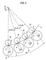
- Fig. 2 is a view showing a roller arrangement of a preliminary heating section of the second embodiment of the present invention.
- Fig. 3 is a view showing a roller arrangement of a preliminary heating section of the third embodiment of the present invention.
- Fig. 4 shows a schematic structural view of a heat developing apparatus provide with the preliminary heating section of the object of the present invention.
- Fig. 5 is a side view showing an example of the roller arrangement according to the present invention.
- Fig. 6 is a perspective view of the roller arrangement in Fig. 5.
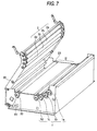
- Fig. 7 is a perspective view of a main portion [heating section (the preliminary heating section I and the developing section II) and the cooling section IV] of the heat developing apparatus having the roller arrangement in Fig. 6.
- Fig. 4 is a schematic structural view of a heat developing apparatus provided with a preliminary heating section which is a subject of the present invention.
- This heat developing apparatus 1 heats the sheet A, and as this sheet A, for example, a plate-making recording material whose size in the width direction is large, and the thickness is thin, and specifically, as described in specification P2000-241928A applied by the present applicant, the heat developing photosensitive material which is characterized in that it has an image forming layer including at least (a) non-photosensitive organic silver salt, (b) photosensitive silver halide, (c) reduction agent, and (d) nucleating agent, on a substrate, and a portion not smaller than 50 weight % of the binder of the image forming layer is formed by using the latex of the polymer whose glass transition temperature not lower than -30 °C and not higher than 40 °C, and after the image forming layer is coated on the substrate and dried, the film surface temperature is not smaller than 30 °C and not larger than 70 °C, and the heating processing is conducted at the temperature not larger than the glass transition temperature of the substrate, can be listed.
- the heat developing apparatus 1 is provided with a preliminary heating section I, developing section II, exhaust section III, and slow cooling section IV, as a main structure.
- the sheet A is supplied from a sheet supply port 31 of the heat developing apparatus 1, and initially, passes through a preliminary heating section I.
- the preliminary heating section I is a section which preliminarily heats the sheet A and raises the temperature to the heat developing temperature, and is structured by a plurality pairs of nip rollers which are heat rollers.
- the subject of the present invention is this preliminary heating section I, and this will be described later.
- this heater unit is composed of an aluminium sheet metal of the lower side arrangement, which is flock-processed by a flock material 6 nylon, a heater, a portion of which is surrounded by this aluminium sheet plate, and an iron (SECC) sheet metal as an auxiliary heating body of the upper side arrangement which is flock-processed by a flock material 6 nylon in the same manner, the sheet A entered into this heater unit is passed through between the aluminium sheet metal of the lower side, and the iron sheet metal of the upper side, while being heated by the heater, and at the time, the sheet is moved slidingly on the tactile hair, without pressing it.
- Gas generated from the preliminary heating section I, developing section II is sucked from a chamber section 35 into the exhaust path 36, and passes through a deodorant filter 37 to be cleaned, and then, discharged to the outside of
- the cooling section IV On the downstream side of the sheet conveying direction of the developing section II, the cooling section IV is arranged, and after the sheet A is heat developing processed in the developing section II, it is conveyed to the cooling section IV by a nip roller 33, and cooled. In this manner, the sheet A on which the heat developing is completed, is delivered from the exit, and is stacked on a film receiving tray 34 provided outside the apparatus.
- a group of 1a through 1d is heating rollers which are a drive section, and a group of 2a -through 2d is conveying rollers which are a driven section, and A is a heat developing sheet on which a latent image by the exposure is formed. This sheet A is finally heated to the developing temperature in the developing section through this preliminary heating means.
- the conveyance rollers 2a through 2d are arranged inside and the heating rollers 1a throughld are arranged outside, and each of heating rollers 1a -through 1d is set so that the heating temperature is gradually increased in this order.
- a temperature of the temperature difference level which is not quickly changed so that the processing quality deterioration due to the wrinkle generation of the sheet A is not accompanied, is respectively set.
- the arrangement and interval of them are respectively set.
- the heating rollers 1a through 1d respectively have, although not shown, a thick wall metallic pipe, and a heat source section arranged at the axis center of the metallic pipe, and a plurality of members whose heat conductivity is not smaller than the metallic pipe, are buried at an equal interval in the peripheral direction of the thick wall portion of the metallic pipe.
- the surface material of the rotating body of the conveying rollers 2a through 2d is formed of silicon rubber.
- the rotating body pairs (1a - 2a, 1b - 2b, 1c - 2c, 1d - 2d) nip the sheet Aby the self weight load of the rotating bodies 2a-through 2d, and when the rotating bodies (conveying rollers) 2a-through 2d, arranged above the rotating body pairs can be moved in the direction of the surface connecting the axis center of the rotating body pairs, the rotating body pairs of the object can be obtained by a simple structure and at a low cost.
- the leading edge of the sheet A is nipped by the heating roller 1a and the conveying roller 2a, and heated while being conveyed.
- the leading edge of the sheet A conveyed from the heating roller 1a and the conveying roller 2a is, as shown by the dotted line, advances to the tangential direction of its nip point O and comes into contact with a point D on the heating roller 1b of the adjoining rotating body pair b. As shown in Fig.
- step 1 the insertion port
- step 2 it is brought into contact with the conveying roller 2a at the nip portion between the conveying roller 2a and the heating roller 1a
- step 3 it is separated at F of the conveying roller 2a
- step 4 comes into contact with E of the conveying roller 2b
- step 5 it is separated from f of the conveying roller 2b
- step 6 it comes into contact with E of the conveying roller 2c
- step 6 it is separated at F of the conveying roller 2b
- step 7 it comes into contact with E of the conveying roller 2c
- step 8 it is separated at F of the conveying roller 2c
- step 9 it comes into contact with E of the conveying roller 2d.
- the sheet A is conveyed while its conveying direction is being changed along the conveying roller outer shape for each nip point of each rotating body pair from the insertion port. Because the sheet A has the bend deformation when it is brought into the heating roller, the buckling deformation due to the heat expansion and contraction generated in the sheet width direction (the perpendicular direction to the conveying direction)is hardly generated, that is, the wrinkle is hardly generated, and thereby, the processing quality is increased.
- the temperature setting value of each heating roller can be set higher, and in a degree in which the processing quality is not affected, the number of heating stages by which heating is conducted in stages to the developing temperature, can be reduced.
- reference signs 1a through 1d are heating rollers as in Fig. 1, and 2a- through 2d are conveying rollers, and A is a heat developing sheet on which a latent image is formed by the exposure, and it is heated to the developing temperature through the preliminary heating means from now.
- the conveying rollers 2a-through 2d are respectively arranged inside, and heating rollers 1a through 1d are arranged outside, and the heating temperature of each of heating rollers 1a through 1d is set higher in this order, and a temperature of temperature difference level by which the processing quality deterioration due to the wrinkle generation of the sheet A is not accompanied, is respectively set, and corresponding to that, those arrangements and intervals are respectively set.
- the heating roller 1 has, although not shown, a thick wall metallic pipe, and a heat source section arranged at the axis center of the metallic pipe, and a plurality of members whose heat conductivity is not smaller than the metallic pipe, are buried at an equal interval in the peripheral direction of the thick wall portion of the metallic pipe.
- the surface material of the rotating body of the conveying roller 2 is formed of silicon rubber.
- the rotating body pairs nip the sheet A by the self weight load of the rotating bodies, and also by making the rotating bodies (conveying rollers) arranged above the rotating body pairs be movable in the direction of the surface connecting the axis center of the rotating body pairs, the rotating body pairs of the object can be obtained with a simple structure and at a low cost.
- a point in which, after the heat developing sheet A is brought into contact from the tangential line direction E' of a point on the outer periphery of one rotating body 2a constituting the rotating body pair 1a - 2a, the sheet A is nipped, is characteristic.
- the cross point of the straight lines passing both axes of each of rotating body pair 1- 2 in Fig. 1 is the same point O 1
- the cross point of the straight lines passing both axes of each of rotating body pair 1- 2 in Fig. 2 is shifted like as O 1 , O 2 and O 3 .
- the sheet A is inserted into the first rotating body pair 1a - 2a from the arrowed direction in the drawing.
- the conveying direction of the sheet A coincides with the tangential direction of the point E' on the conveying roller 2a, and the leading edge of the sheet A is brought into contact with the point E' on the conveying roller 2a at first, and after the sheet A is wound by a predetermined angle (in the example, 15°) along the outer shape of the conveying roller 2a, it is nipped and heated by the rotating body pair.
- the sheet A passed through the nipping point O is separated from the conveying roller 2a and advances to the contact point E' on the conveying roller 2b as it is.
- the sheet A is conveyed from the tangential direction of the point E' on the conveying roller 2b, to this rotating body pair 1b - 2b.
- the third and subsequent rotating body pairs 1c - 2c, 1d - 2d are the same as described above.
- Fig. 1 As described above, four rotating body pairs are arranged so that each of nipping points of four rotating body pairs by which the sheet is nipped and the sheet temperature is heated to the developing temperature and the sheet is conveyed, is positioned on the same curvature line of the radius R whose central point is a position of O 1 , and further, angles B of the straight lines connecting the nipping points of the adjoining rotating body pairs with the center of curvature O 1 become the same.
- the sheet A is conveyed while its conveying direction is changed along the outer shape of the conveying roller, for each nipping point of each of rotating body pairs from the insertion port, the buckling deformation due to the heat expansion and compression generated in the sheet width direction (the perpendicular direction to the conveying direction) is hardly generated, that is, the wrinkle is hardly generated, and the processing quality is increased.
- the processing quality deterioration becomes conspicuous depending on the performance of the sheet because the conveying behavior of the leading edge portion of the sheet is a little different from that of the subsequent portion, and the heat developing condition is a little different.
- the conveying behavior whose heat developing condition is a little different is, specifically speaking, for example, the sheet leading edge conveying behavior between the rotating body pairs c and d in Fig. 1 is as follows: after the leading edge is brought into contact with the point D on the heating roller 1d, it advances to the nip portion sliding on the circumference of the heating roller 1d.
- the behavior of the sheet in the vicinity of the back rotating body pair c is as follows: a portion in contact with the circumference of the rubber roller 2c becomes large. That is, the leading edge portion of the sheet from the portion nipped by the rotating body pair to the portion nipped by the back rotating body pair is a few different from the subsequent sheet in the demand and supply of the heat energy.
- the conveying direction of the sheet A is changed along the outer shape of the conveying roller at each nipping point of each rotating body pair from the insertion port of the sheet A and the sheet A is conveyed, other than the characteristic possessed by the first embodiment in which the buckling deformation due to the heat expansion and compression generated in the sheet width direction (perpendicular direction to the conveying direction) is hardly generated, that is, the wrinkle is hardly generated, and the processing quality is increased, when this structure is adopted, the sheet leading edge area in which the behavior between the sheet leading edge portion and the subsequent portion is different, can be reduced, and an area of the image quality deterioration, generated by the developing time error or the temperature error on the sheet surface generated due to the difference of the behavior, can be reduced.
- Fig. 3 shows the roller arrangement of the preliminary heating section showing the third embodiment of the present invention.
- a group 1a - 1d is heating rollers which are a drive section
- a group 2a - 2d is conveying rollers which are a driven section
- A is a heat developing sheet on which a latent image by the exposure is formed, and after through this preliminary heating means, this sheet A is finally heated to the developing temperature in the developing section.
- Fig. 3 shows the roller arrangement of the preliminary heating section showing the third embodiment of the present invention.
- a group 1a - 1d is heating rollers which are a drive section
- a group 2a - 2d is conveying rollers which are a driven section
- A is a heat developing sheet on which a latent image by the exposure is formed, and after through this preliminary heating means, this sheet A is finally heated to the developing temperature in the developing section.
- the first roller pair 1a - 2a and the second roller pair 1b - 2b are arranged so that the straight line La connecting the both axes of the first roller pair 1a and 2a, and the straight line Lb connecting both axes of the second roller pair 1b and 2b are in parallel with each other, thereby, the system is structured so that, at the time of the conveyance of the sheet A, the sheet A does not have the curl deformation.
- the arrangement of the rotating body pairs 1b and 1c, and 1c and 1d is conducted so that, as described in the first and the second embodiment, the sheet A generates the curl deformation.
- the rotating body pairs are arranged so that the degree of the curl deformation is different between rotating body pairs 1b and 1c (the cross point of both axes is B1), and 1c and 1d (the cross point of the both axes is B2).
- Fig. 5 is a side view showing an example of the roller arrangement according to the present invention of the preliminary heating section, and the arrangement of the second embodiment is shown herein.
- numeral 1a through 1d is the heating rollers which is a drive section
- 2a through 2d is conveying rollers.
- An example of the arrangement and interval of each of heating rollers 1a through 1d and each of conveying rollers 2a through 2d are as follow.
- the axis of the heating roller 1d is made the center, and the axis of the heating roller 1c is arranged at a point of 48. 7 mm in the lateral direction, and 11.5 mm in the upper direction, and the axis of the heating roller 1b is arranged at a point of 92. 8 mm in the lateral direction and 35.2 mm in the upper direction, and the axis of the heating roller 1a is arranged at a point of 129. 2 mm in the lateral direction and 69.5 mm in the upper direction.
- the axis of the conveying roller 2d is made the center, and the axis of the conveying roller 2c is arranged at a point of 39.0 mm in the lateral direction, and 10. 2 mm in the upper direction, and the axis of the conveying roller 2b is arranged at a point of 74. 0 mm in the lateral direction and 30. 2 mm in the upper direction, and the axis of conveying roller 2a is arranged at a point of 102. 6 mm in the lateral direction and 58. 5 mm in the upper direction.
- the arrangement of the rollers in Fig. 2 can be realized.
- Fig. 6 is a perspective view of the roller arrangement in Fig. 5.
- numeral 1a through 1d is heating rollers which is a drive section
- 2a through 2d is conveying rollers. That is, the conveying rollers 2a through 2d are arranged inside (upper side), and heating rollers 1a through 1d are arranged outside (lower side).
- Each heating roller 1 is composed of a wall-thick metallic pipe, and a heat source section arranged at the axial center of the metallic pipe, and a plurality of members whose heat conductivity is not smaller than that of the metallic pipe are buried at an equal interval in the peripheral direction of the wall-thick portion of the metallic pipe.
- the rotating body surface material is formed of silicon rubber.
- Fig. 7 is a perspective view of the interior (preliminary heating section I, developing section II, cooling section IV) of the heat developing apparatus which has the roller arrangement in Fig. 6.
- the upper lid (conveying rollers 2a through 2d) side of the heating section is shown as an opened condition, and when the upper lid is closed, it becomes a condition as in Fig. 6.
- the sheet enters into the preliminary heating section I, and the sheet is preliminarily heated in the preliminary heating section, and its temperature rises to the heat developing temperature, then, the sheet is conveyed to the developing section II.
- the developing section II the sheet passes sliding on the heat plate which is the heating body, at the developing temperature.
- the sheet is conveyed to the cooling section by the nip roller 33, and cooled herein, and the sheet on which the heat development is completed, is delivered from the exit, and stacked on the tray.
Landscapes
- Physics & Mathematics (AREA)
- General Physics & Mathematics (AREA)
- Photographic Developing Apparatuses (AREA)
Abstract
Description
(2) It is effective when it is desired that the curvature which is owned by the sheet at the initial condition, is relieved by heating, that is, when the conveyance property is secured by eliminating the positive deformation at the initial stage of the heating.
(3) It is effective when it is desired that the restriction by the arrangement to the exposure system by which the latent image is recorded on the sheet, is removed.
Claims (7)
- A heat developing apparatus in which a heat developing sheet on which a latent image is formed by the exposure, and is heated to the developing temperature through a preliminary heating means, characterized in that:the preliminary heating means has a plurality of rotating body pairs for nipping the heat developing sheet and for heating-conveying it to the developing temperature; andthe rotating body pairs are arranged so that the conveying direction of the heat developing sheet is changed by at least one pair of rotating body pair in the plurality of rotating body pairs.
- A heat developing apparatus in which a heat developing sheet on which a latent image is formed by the exposure and is heated to the developing temperature through a preliminary heating means, characterized in that:the preliminary heating means has a plurality of rotating body pairs for nipping the heat developing sheet and for heating-conveying it to the developing temperature;the rotating body pairs are arranged so that the conveying direction of the heat developing sheet is changed by at least one pair of rotating body pair in the plurality of rotating body pairs; andafter the heat developing sheet is brought into contact with the rotating body from the tangential line direction of a point on an outer periphery of one rotating body constituting the rotating body pairs, the heat developing sheet is nipped.
- A heat developing apparatus according to Claims 1 or 2, wherein
respective changes of the conveying direction of the heat developing sheet at the plurality of rotating body pairs are the same rotating direction around the axial center of one rotating body which is respectively arranged in the same manner in the respective rotating body pairs. - A heat developing apparatus according to any one of Claims 1 to 3, wherein
each of the plurality of rotating body pairs are structured by two rollers, and at least one roller is a heating roller in which the heating means is provided; and
arrangement, interval and temperature of the heating roller are set so as to have the temperature difference by which the heat developing processing quality deterioration due to the heat deformation of the heat developing sheet is not generated. - A heat developing apparatus according to Claim 4, wherein
the heating roller comprises a thick-wall metallic pipe,
heat source portion arranged on the axis center of the metallic pipe, and
a plurality of members whose heat conductivity is greater than the metallic pipe, are buried at an equal interval in the peripheral direction of the wall thickness portion of the metallic pipe. - A heat developing apparatus according to any one of claims 1 to 5, wherein
the rotating body surface material of the plurality of rotating body pairs which is brought into contact with the surface on which a material forming a latent image of the heat developing sheet is coated, is formed of silicon rubber, and
the heat developing sheet is deformed and conveyed in the same rotation direction as the rotation body around the axis center of the rotating body structuring the surface by the silicon rubber. - A heat developing apparatus according to any one of claims 1 to 6, wherein
the rotating body pair nips the heat developing sheet by the self weight load of the rotating body, and the rotating body arranged above the rotating body pair can be moved in the surface direction in which the axis centers of the rotating body pairs are connected.
Applications Claiming Priority (2)
| Application Number | Priority Date | Filing Date | Title |
|---|---|---|---|
| JP2001032468A JP3934350B2 (en) | 2001-02-08 | 2001-02-08 | Thermal development device |
| JP2001032468 | 2001-02-08 |
Publications (3)
| Publication Number | Publication Date |
|---|---|
| EP1231507A2 true EP1231507A2 (en) | 2002-08-14 |
| EP1231507A3 EP1231507A3 (en) | 2002-09-18 |
| EP1231507B1 EP1231507B1 (en) | 2004-08-11 |
Family
ID=18896394
Family Applications (1)
| Application Number | Title | Priority Date | Filing Date |
|---|---|---|---|
| EP02002794A Expired - Lifetime EP1231507B1 (en) | 2001-02-08 | 2002-02-07 | Apparatus for thermal developing of a latent image |
Country Status (4)
| Country | Link |
|---|---|
| US (1) | US6753949B2 (en) |
| EP (1) | EP1231507B1 (en) |
| JP (1) | JP3934350B2 (en) |
| DE (1) | DE60200896T2 (en) |
Families Citing this family (10)
| Publication number | Priority date | Publication date | Assignee | Title |
|---|---|---|---|---|
| JP3805707B2 (en) * | 2002-03-26 | 2006-08-09 | 富士写真フイルム株式会社 | Image recording device |
| JP3808042B2 (en) * | 2003-02-04 | 2006-08-09 | 富士写真フイルム株式会社 | Thermal development recording device |
| US7158164B2 (en) * | 2003-08-29 | 2007-01-02 | Fuji Photo Film Co., Ltd. | Thermal development method and apparatus |
| WO2006070654A1 (en) * | 2004-12-28 | 2006-07-06 | Konica Minolta Medical & Graphic, Inc. | Heat developing system and method |
| JP6254821B2 (en) * | 2013-02-19 | 2017-12-27 | 株式会社リコー | Recording medium heating apparatus and system having the same |
| JP6417782B2 (en) * | 2014-05-29 | 2018-11-07 | 株式会社リコー | Recording medium heating apparatus, printing apparatus, pretreatment liquid coating / drying apparatus, and printing system |
| US9605900B2 (en) | 2015-04-22 | 2017-03-28 | Ricoh Company, Ltd. | Adjustable interlacing of drying rollers in a print system |
| JP2017211151A (en) * | 2016-05-27 | 2017-11-30 | 株式会社リコー | Drying equipment |
| US9994049B1 (en) | 2017-02-13 | 2018-06-12 | Ricoh Company, Ltd. | Adjustable path length of print media in a dryer of a printing system |
| US9908342B1 (en) | 2017-02-26 | 2018-03-06 | Ricoh Company, Ltd. | Concentric arrangement of web conditioning modules in a dryer of a print system |
Family Cites Families (9)
| Publication number | Priority date | Publication date | Assignee | Title |
|---|---|---|---|---|
| US3288047A (en) * | 1965-03-29 | 1966-11-29 | Lumonrint Zindler K G | Apparatus for exposing and developing sensitive sheets |
| JPH06311727A (en) * | 1993-04-20 | 1994-11-04 | Toshiba Corp | Overvoltage protection device and power conversion device |
| US5869807A (en) * | 1996-02-02 | 1999-02-09 | Imation Corp. | Apparatus and method for thermally processing an imaging material employing improved heating means |
| JPH10128946A (en) * | 1996-10-30 | 1998-05-19 | Riso Kagaku Corp | Plate making equipment |
| US5750260A (en) * | 1996-11-22 | 1998-05-12 | Imation Corp | Development/transport rollers having a fluorocarbon coating for use in automated thermal development equipment |
| US5893003A (en) * | 1997-09-30 | 1999-04-06 | Imation Corp. | Compensation method and system for density loss in an imaging apparatus |
| JP3296482B2 (en) * | 1998-08-13 | 2002-07-02 | 富士写真フイルム株式会社 | Thermal development device |
| JP2000241928A (en) | 1999-02-19 | 2000-09-08 | Fuji Photo Film Co Ltd | Heat-developable photosensitive material |
| JP3773162B2 (en) * | 1999-05-20 | 2006-05-10 | 富士写真フイルム株式会社 | Thermal development device |
-
2001
- 2001-02-08 JP JP2001032468A patent/JP3934350B2/en not_active Expired - Fee Related
-
2002
- 2002-02-07 DE DE60200896T patent/DE60200896T2/en not_active Expired - Lifetime
- 2002-02-07 US US10/067,294 patent/US6753949B2/en not_active Expired - Fee Related
- 2002-02-07 EP EP02002794A patent/EP1231507B1/en not_active Expired - Lifetime
Also Published As
| Publication number | Publication date |
|---|---|
| JP3934350B2 (en) | 2007-06-20 |
| EP1231507A3 (en) | 2002-09-18 |
| US20020105630A1 (en) | 2002-08-08 |
| JP2002236344A (en) | 2002-08-23 |
| US6753949B2 (en) | 2004-06-22 |
| EP1231507B1 (en) | 2004-08-11 |
| DE60200896D1 (en) | 2004-09-16 |
| DE60200896T2 (en) | 2005-07-28 |
Similar Documents
| Publication | Publication Date | Title |
|---|---|---|
| EP1231507B1 (en) | Apparatus for thermal developing of a latent image | |
| JP3218941B2 (en) | Fixing device | |
| US20080063442A1 (en) | Fixing device and image forming apparatus | |
| US6611315B2 (en) | Thermal development sheet cooling method, and thermal development apparatus | |
| EP0283214A2 (en) | Curling prevention device of thermal developing machine | |
| JP2001265146A (en) | Heat fixing device | |
| US7108433B2 (en) | Thermal processor employing varying roller spacing | |
| EP0560248B1 (en) | Photosensitive material drying method and apparatus | |
| JP7479983B2 (en) | Heating device and image processing device | |
| JPS6333152B2 (en) | ||
| JP3161483B2 (en) | Transport guide device for fixing device | |
| JP2020016769A (en) | Fixing device and image forming device | |
| JP3397934B2 (en) | Fixing device | |
| JP3840907B2 (en) | Fixing device | |
| JP3329763B2 (en) | Thermal development device | |
| JPH0769507A (en) | Curved paper correcting device | |
| JP3115799B2 (en) | roller | |
| JPS60151678A (en) | Fusing device | |
| JPH08220913A (en) | Fixing device | |
| JPS62294273A (en) | Heat roll fixing device | |
| JP2002258651A (en) | Fixing device | |
| JP2001026352A (en) | Image forming device | |
| JP2000089607A (en) | Fixing device | |
| JP2004184756A (en) | Fixing device | |
| JP2000242124A (en) | Fixing device |
Legal Events
| Date | Code | Title | Description |
|---|---|---|---|
| PUAI | Public reference made under article 153(3) epc to a published international application that has entered the european phase |
Free format text: ORIGINAL CODE: 0009012 |
|
| PUAL | Search report despatched |
Free format text: ORIGINAL CODE: 0009013 |
|
| AK | Designated contracting states |
Kind code of ref document: A2 Designated state(s): AT BE CH CY DE DK ES FI FR GB GR IE IT LI LU MC NL PT SE TR |
|
| AX | Request for extension of the european patent |
Free format text: AL;LT;LV;MK;RO;SI |
|
| AK | Designated contracting states |
Kind code of ref document: A3 Designated state(s): AT BE CH CY DE DK ES FI FR GB GR IE IT LI LU MC NL PT SE TR |
|
| AX | Request for extension of the european patent |
Free format text: AL;LT;LV;MK;RO;SI |
|
| 17P | Request for examination filed |
Effective date: 20021104 |
|
| 17Q | First examination report despatched |
Effective date: 20030121 |
|
| AKX | Designation fees paid |
Designated state(s): DE FR GB |
|
| GRAP | Despatch of communication of intention to grant a patent |
Free format text: ORIGINAL CODE: EPIDOSNIGR1 |
|
| GRAS | Grant fee paid |
Free format text: ORIGINAL CODE: EPIDOSNIGR3 |
|
| GRAA | (expected) grant |
Free format text: ORIGINAL CODE: 0009210 |
|
| AK | Designated contracting states |
Kind code of ref document: B1 Designated state(s): DE FR GB |
|
| REG | Reference to a national code |
Ref country code: GB Ref legal event code: FG4D |
|
| REG | Reference to a national code |
Ref country code: IE Ref legal event code: FG4D |
|
| REF | Corresponds to: |
Ref document number: 60200896 Country of ref document: DE Date of ref document: 20040916 Kind code of ref document: P |
|
| ET | Fr: translation filed | ||
| PLBE | No opposition filed within time limit |
Free format text: ORIGINAL CODE: 0009261 |
|
| STAA | Information on the status of an ep patent application or granted ep patent |
Free format text: STATUS: NO OPPOSITION FILED WITHIN TIME LIMIT |
|
| 26N | No opposition filed |
Effective date: 20050512 |
|
| REG | Reference to a national code |
Ref country code: GB Ref legal event code: 732E |
|
| REG | Reference to a national code |
Ref country code: FR Ref legal event code: CD Ref country code: FR Ref legal event code: TP |
|
| PGFP | Annual fee paid to national office [announced via postgrant information from national office to epo] |
Ref country code: FR Payment date: 20120221 Year of fee payment: 11 |
|
| PGFP | Annual fee paid to national office [announced via postgrant information from national office to epo] |
Ref country code: DE Payment date: 20120131 Year of fee payment: 11 |
|
| PGFP | Annual fee paid to national office [announced via postgrant information from national office to epo] |
Ref country code: GB Payment date: 20120201 Year of fee payment: 11 |
|
| GBPC | Gb: european patent ceased through non-payment of renewal fee |
Effective date: 20130207 |
|
| REG | Reference to a national code |
Ref country code: FR Ref legal event code: ST Effective date: 20131031 |
|
| REG | Reference to a national code |
Ref country code: DE Ref legal event code: R119 Ref document number: 60200896 Country of ref document: DE Effective date: 20130903 |
|
| PG25 | Lapsed in a contracting state [announced via postgrant information from national office to epo] |
Ref country code: FR Free format text: LAPSE BECAUSE OF NON-PAYMENT OF DUE FEES Effective date: 20130228 Ref country code: DE Free format text: LAPSE BECAUSE OF NON-PAYMENT OF DUE FEES Effective date: 20130903 Ref country code: GB Free format text: LAPSE BECAUSE OF NON-PAYMENT OF DUE FEES Effective date: 20130207 |