EP1231416A2 - Shaft seal and gas turbine - Google Patents
Shaft seal and gas turbine Download PDFInfo
- Publication number
- EP1231416A2 EP1231416A2 EP01125628A EP01125628A EP1231416A2 EP 1231416 A2 EP1231416 A2 EP 1231416A2 EP 01125628 A EP01125628 A EP 01125628A EP 01125628 A EP01125628 A EP 01125628A EP 1231416 A2 EP1231416 A2 EP 1231416A2
- Authority
- EP
- European Patent Office
- Prior art keywords
- plate
- thin plates
- rotary shaft
- pressure side
- low pressure
- Prior art date
- Legal status (The legal status is an assumption and is not a legal conclusion. Google has not performed a legal analysis and makes no representation as to the accuracy of the status listed.)
- Granted
Links
Images






Classifications
-
- F—MECHANICAL ENGINEERING; LIGHTING; HEATING; WEAPONS; BLASTING
- F16—ENGINEERING ELEMENTS AND UNITS; GENERAL MEASURES FOR PRODUCING AND MAINTAINING EFFECTIVE FUNCTIONING OF MACHINES OR INSTALLATIONS; THERMAL INSULATION IN GENERAL
- F16J—PISTONS; CYLINDERS; SEALINGS
- F16J15/00—Sealings
- F16J15/16—Sealings between relatively-moving surfaces
- F16J15/32—Sealings between relatively-moving surfaces with elastic sealings, e.g. O-rings
- F16J15/3284—Sealings between relatively-moving surfaces with elastic sealings, e.g. O-rings characterised by their structure; Selection of materials
- F16J15/3292—Lamellar structures
Definitions
- the present invention relates to a shaft seal which is used in a rotary shaft and the like of a large-scale fluid machine, such as a gas turbine, a steam turbine, a compressor, a waterwheel, a refrigerator, and a pump.
- a gas turbine which leads gas of high temperature and high pressure into a turbine, expands the gas therein, and generates dynamic force by converting thermal energy of the gas to mechanical rotation energy, and a shaft seal which is suitably used in a shaft comprising the gas turbine.
- a shaft seal for reducing the amount of gas which leaks from the high pressure side to the low pressure side is provided between stationary blades and the rotary shaft.
- a non-contacting labyrinth seal has been widely used.
- the gap between the tips of the fins must be increased by a certain amount so that the tips of the fins do not contact due to an axial vibration or an excessive thermal deformation during transient rotation. Consequently, a large amount of gas is leaked.
- a brush seal has been developed with the aim of reducing the amount of leakage.
- FIGS. 16A and 16B are schematic diagrams showing the constitution of this type of brush seal.
- reference numeral 1 represents a rotary shaft
- reference numeral 2 represents a casing
- reference numeral 3 represents a low pressure side side-plate
- reference numeral 4 represents a high pressure side side-plate
- reference numeral 5 represents a brazing section
- reference numeral 6 represents wires.
- the wires 6 is made of filaments which have a diameter of 50 to 100 ⁇ m and are flexible enough to be able to absorb decentering caused the vibration of the rotary shaft 1 or by thermal deformation.
- the wires 6 are bundled tightly into a bundle having a width of 3 to 5 mm so that there are no gaps between them.
- the wires 6 are attached at a gradient to the direction of rotation so as to form an acute angle with the outer periphery of the rotary shaft 1.
- the tips of the wires 6 touch the outer periphery of the rotary shaft 1 with a predetermined preliminary pressure, thereby reducing the amount of leakage in the axial direction.
- the wires 6 slide against the rotary shaft 1 while contacting, generating heat dependent on atmospheric conditions or peripheral speed and becoming red-hot. For this reason, a material which is resistance to high temperatures, such as INCONEL alloy or HASTELLOY alloy, is used for the wires 6 in accordance with the conditions of use. Since the sliding face on the outer rim of the rotary shaft 1 is corroded together with the wires 6, it is coated with a corrosion-resistant material. Moreover, since the wires 6 have little flexibility in the axial direction of the rotary shaft 1, the wires 6 are prevented from being damaged by making the inside diameter of the low pressure side side-plate 3 substantially equal to the outer rim of the rotary shaft 1.
- the leaf seal 10 comprises flat thin plates 18 having a predetermined width, provided in multiple layers in the axial direction of the rotary shaft 11 at the rim thereof.
- the outer base ends of the thin plates 18 are brazed inside a casing 12, that is, the thin plate 18 is attached to the casing by brazing section 15, the sealing the outer rim of the rotary shaft 11 and thereby dividing the peripheral space of the rotary shaft 11 into a high pressure region and a low pressure region.
- a high pressure side side-plate 14 and a low pressure side side-plate 13 are attached respectively in the high pressure region and the low pressure region at both sides of the thin plates 18, and function as guides in the direction of pressure.
- the thin plates 18 have predetermined rigidity, which is determined by the thickness of the plates, in the axial direction of the rotary shaft 11.
- the thin plates 18 are attached to the casing 12 so that the angle they form with the rim of the rotary shaft 11 is acute with respect to the axial direction of the rotary shaft 11.
- the tips of the thin plates 18 contact the rotary shaft 11 with a predetermined pressure when the rotary shaft 11 is stationary, the dynamic pressure created by the rotation of the rotary shaft 11 causes the tips of the thin plates 18 to rise upward when the rotary shaft 11 is rotating, so that there is no contact between the thin plates 18 and the rotary shaft 11.
- each gap 19 is provided between each of the laminated flat thin plates 18. Since the seal diameter is sufficiently large, i.e. since the diameter of the rotary shaft 11 is sufficiently large, each gap 19 can be regarded as approximately constant from the outer side of the rim to the inner side of the rim.
- the thin plates 18 having a width in the axial direction of the rotary shaft 11 are laminated in the peripheral direction of the rotary shaft 11.
- the thin plates 18 have gentle flexibility in the peripheral direction of the rotary shaft 11, and the seal mechanism has high rigidity in the axial direction of the rotary shaft 11.
- the rigidity of the wires 6 which comprise the brush seal is determined by their ability to follow the axial vibration of the rotary shaft 1, the appropriate pressure against the rotary shaft 1, and the like, and there is a limit on the extent to which flexibility can be increased by increasing the diameter of the wires 6 and the like. Therefore, the seal differential pressure in the axial direction of the rotary shaft 1, which is dependent on the flexibility of the wires 6, has a maximum of approximately 0.5 MPa, and no differential pressure larger than this can be sealed.
- the wires 6 are extremely thin, in general, they have a diameter of approximately 50 to 100 ⁇ m, there is a danger that the wires 6 will break and fall out as a result of sliding against the rim of the rotary shaft 1; this makes it difficult to use the gas turbine for a long period of time.
- leaf seal 10 described above has the following problems.
- the dynamic pressure generated by the rotation of the rotary shaft 11 causes the tips of the thin plates 18 to rise upward from the surface of the rotary shaft 11, so that there is no contact between the thin plates 18 and the rotary shaft 11.
- This constitution prevents excessive heat generation and corrosion.
- the low pressure side side-plate 13 and the high pressure side side-plate 14 are provided in such a manner that the gap between the low pressure side side-plate 13 and the thin plates 18 is substantially equal to the gap between the high pressure side side-plate 14 and the thin plates 18, when pressure has been applied from the high pressure side, the additional pressure load deforms the thin plates 18 toward the center of the radial direction of the rotary shaft 11, making it difficult to stop the thin plates from touching the rotary shaft 11 when the leaf seal is activated with small dynamic pressure and the like.
- the present invention has been realized in consideration of the matters mentioned above, and aims to provide a shaft seal which reduces the leakage of gas from the high pressure side to the low pressure side, and has excellent corrosion-resistance, and a gas turbine which is equipped with the shaft seal.
- the present invention provide a shaft seal comprising: a plurality of flexible thin plates having width in the axial direction of a rotary shaft, tips thereof sliding against a peripheral face of the rotary shaft, and outer peripheral bases thereof being secured to a casing side maintaining a gap therebetween, the thin plates being laminated in the peripheral direction of the rotary shaft, enabling the outer periphery of the rotary shaft to be sealed, an acute angle being formed between the thin plates and the peripheral face of the rotary shaft; and a low pressure side side-plate and a high pressure side side-plate which are provided on both sides of the thin plates in the axial direction of the rotary shaft, wherein it further comprises a gas pressure adjusting mechanism, which when the thin plates are viewed cross-sectionally along an imaginary plane which is perpendicular to the direction of their width, the face of each thin plate which faces the rotary shaft is deemed a bottom face and the rear side is deemed a top face, and gas pressure from the high pressure side side-plate to the low pressure side
- the gas pressure adjusting mechanism makes a gas pressure distribution such that the gas pressure is highest at the angular section, which is positioned at the tip side and on the side of the high pressure side side-plate, and gradually weakens as it approaches a diagonally opposing angle.
- the gas pressure adjusting mechanism can adjust the gas pressure so that, when the thin plates are viewed in cross-section along an imaginary plane at a right-angle to the direction of their width, and the face of the thin plate which faces the rotary shaft is deemed the bottom face and the rear side is deemed the top face, and gas pressure from the high pressure side side-plate to the low pressure side side-plate is applied to the thin plates, the gas pressure applied to the bottom face is higher than the gas pressure applied to the top face at a given point along the cross-sectional faces of the thin plates. Therefore, the thin plates rise up and do not contact the rotary shaft.
- gas flowing from the high pressure side to the low pressure side flows between the peripheral face of the rotary shaft and the tips of the thin plates, and along the top and bottom faces of the thin plates.
- the gas flowing along the top and bottom faces of the thin plates enters between the high pressure side side-plate and the peripheral face of the rotary shaft, and spreads toward the diagonally opposite angle.
- the gas pressure which strikes the top and bottom faces of the thin plates at a perpendicular gas a triangular distribution, increasing as it nears the tip sections and decreasing as it heads toward the outer peripheral base.
- the thin plates are arranged diagonally so as to form an acute angle with the peripheral face of the rotary shaft, and consequently, the positions of the pressure distribution on the top and bottom faces deviate from each other. That is, when the gas pressures on the top and bottom faces are compared at any given point from the outer peripheral base to the tip side of the thin plate, they are found to be different.
- the thin plates deform and rise up higher than the rotary shaft, acting in this direction.
- the reverse occurs at the section near the tips of the thin plates, gas pressure being applied only to the top face (since the outermost tip sections of the thin plates are cut diagonally so that they touch the peripheral face, there is no section corresponding to the bottom face).
- This force is cancelled out by the pressure of gas flowing between the peripheral face and the tips of the thin plates, which acts in the direction along which the tips of the thin plates rise from the peripheral face (Fc), and consequently, there is no force pressing the tips of the thin plates against the rotary shaft. Therefore, the pressure load of the gas pressure applied to the each thin plate is (Fb + Fc) > Fa, enabling the thin plates to be deformed so as to rise up higher than the peripheral face.
- the size of the section which is affixed to the casing is larger than is the case when using wires of a conventional brush seal, enabling the thin plates to be securely affixed to the casing.
- the tips of the thin plates are highly rigid in the axial direction of the rotary shaft and flexible in the peripheral direction of the rotary shaft, they are unlikely to deform in the direction of differential pressure, enabling the tolerance of the seal differential pressure to be increased and reducing the contact between the thin plates and the rotary shaft when the rotary shaft is vibrating.
- the gas pressure adjusting mechanism comprises the low pressure side side-plate and the high pressure side side-plate, which are positioned so that the size of a low pressure side gap between the thin plates and the low pressure side side-plate is larger than a high pressure side gap between the thin plates and the high pressure side side-plate.
- the gas when pressure is applied from the high pressure side, the gas passes through the thin plates and attempts to flow from the high pressure side to the low pressure side.
- the gap between the thin plates and the low pressure side side-plate is larger than the gap between the thin plates and the high pressure side side-plate, the gas which has entered from between the high pressure side side-plate and the peripheral face of the rotary shaft flows along the top and bottom faces of the thin plates and spreads to the diagonally opposite angle, and simultaneously, a low pressure region expands at the outer peripheral base.
- the distribution of gas pressure against the top and bottom faces can be made triangular at a given point along the cross-sectional face of the thin plates which is perpendicular to the axial direction, gradually decreasing as it approaches the outer peripheral base from the tip side of the thin plates.
- pressure difference is created on the top and bottom faces of the thin plates, causing them to rise up to a state of non-contact with the rotary shaft.
- the gas pressure adjusting mechanism prefferably comprises the high pressure side side-plate, and the low pressure side side-plate of which the length in the radial direction of the rotary shaft is shorter than the length of the high pressure side side-plate in the radial direction of the rotary shaft.
- the gas passes the thin plates and attempts to flow from the high pressure side to the low pressure side.
- the length of the low pressure side side-plate in the rotary shaft radial direction is shorter than the length of the high pressure side side-plate in the rotary shaft radial direction, thereby creating a space on the low pressure side, the gas which has entered from between the high pressure side side-plate and the peripheral face of the rotary shaft flows along the top and bottom faces of the thin plates and spreads to the diagonally opposite angle, and simultaneously, a low pressure region expands at the outer peripheral base.
- the distribution of gas pressure against the top and bottom faces can be made triangular at a given point along the cross-sectional face of the thin plates which is perpendicular to the axial direction, gradually decreasing as it approaches the outer peripheral base from the tip side of the thin plates.
- pressure difference is created on the top and bottom faces of the thin plates, causing them to rise up to a state of non-contact with the rotary shaft.
- the gas pressure adjusting mechanism prefferably comprises a flexible plate, which is flexible in the axial direction of the rotary shaft and is arranged on the high pressure side of the thin plates.
- the gas passes the thin plates and attempts to flow from the high pressure side to the low pressure side.
- the flexible plates which are flexible in the axial direction of the rotary shaft, are provided on the high pressure side of the thin plates (e.g.
- the flexible plate bends as a result of the gas pressure from the high pressure side, reducing the size of the gap between the thin plate and the high pressure side until it is narrower than the gap between the thin plate and the low pressure side. Consequently, the gas which has entered from between the high pressure side side-plate and the peripheral face of the rotary shaft flows along the top and bottom faces of the thin plates and spreads to the diagonally opposite angle, and simultaneously, the low pressure region expands at the outer peripheral base.
- the distribution of gas pressure against the top and bottom faces can be made triangular at a given point along the cross-sectional face of the thin plates which is perpendicular to the axial direction, gradually decreasing as it approaches the outer peripheral base from the tip side of the thin plates.
- pressure difference is created on the top and bottom faces of the thin plates, causing them to rise up to a state of non-contact with the rotary shaft.
- the gas pressure adjusting mechanism prefferably comprises slitted flexible plates, which are flexible in the axial direction of the rotary shaft, are arranged on the high pressure side of the thin plates, and comprise slits at more than two places along the entire rim thereof.
- the gas passes the thin plates and attempts to flow from the high pressure side to the low pressure side.
- the slitted flexible plates which are flexible in the axial direction of the rotary shaft and have slits at more than two places along their entire rim, are provided on the high pressure side of the thin plates (e.g.
- the flexible plate bends as a result of the gas pressure from the high pressure side, reducing the size of the gap between the thin plate and the high pressure side until it is narrower than the gap between the thin plate and the low pressure side.
- the gas which has entered from between the high pressure side side-plate and the peripheral face of the rotary shaft flows along the top and bottom faces of the thin plates and spreads to the diagonally opposite angle, and simultaneously, the low pressure region expands at the outer peripheral base. Therefore, the distribution of gas pressure against the top and bottom faces can be made triangular at a given point along the cross-sectional face of the thin plates which is perpendicular to the axial direction, gradually decreasing as it approaches the outer peripheral base from the tip side of the thin plates. For the reasons mentioned above, pressure difference is created on the top and bottom faces of the thin plates, causing them to rise up to a state of non-contact with the rotary shaft.
- the gas pressure adjusting mechanism prefferably comprises a low pressure side side-plate in which a plurality of draft holes passing through the low pressure side side-plate in the axial direction of the rotary shaft.
- the gas when pressure is applied from the high pressure side, the gas passes the thin plates and attempts to flow from the high pressure side to the low pressure side.
- the plurality of draft holes are provided through the low pressure side side-plate in the axial direction of the rotary shaft (e.g. by providing a plurality of draft holes passing through the low pressure side side-plate toward the axial direction of the rotary shaft, or by using a porous material as the low pressure side side-plate, and the like)
- the gas which has entered from between the high pressure side side-plate and the peripheral face of the rotary shaft flows along the top and bottom faces of the thin plates and spreads to the diagonally opposite angle, and simultaneously, the low pressure region expands at the outer peripheral base.
- the distribution of gas pressure against the top and bottom faces can be made triangular at a given point along the cross-sectional face of the thin plates which is perpendicular to the axial direction, gradually decreasing as it approaches the outer peripheral base from the tip side of the thin plates.
- a pressure difference is created between the top and bottom faces of the thin plates, causing them to rise up to a state of non-contact with the rotary shaft.
- the shaft seal further comprises a gap size adjusting mechanism, which is provided between the low pressure side side-plate and the thin plates, for supporting the thin plates and maintaining the size of the gap between the low pressure side side-plate and the thin plates when the thin plates attempt to move toward the low pressure side side-plate.
- a gap size adjusting mechanism which is provided between the low pressure side side-plate and the thin plates, for supporting the thin plates and maintaining the size of the gap between the low pressure side side-plate and the thin plates when the thin plates attempt to move toward the low pressure side side-plate.
- the gap size adjusting mechanism prefferably comprises a first step section, which is provided on the side of the low pressure side side-plate so as to protrude toward the thin plates side; and the first step section forms a ring which runs along the low pressure side side-plate around the rotary shaft.
- the first step section prefferably comprises ventilation holes for forming a space which joins the rotary shaft radial direction inner peripheral side and the rotary shaft radial direction outer peripheral side between the thin plate and the low pressure side side-plate.
- the ventilation holes are provided in the first step section comprising the gap size adjusting mechanism, resistance to the flow of gas between the rotary shaft radial direction inner peripheral side and the rotary shaft radial direction outer peripheral side, is reduced in the gap space between the thin plate and the low pressure side side-plate with the step section as a boundary. Consequently, the first step section continues to support the thin plates, while achieving pressure distribution in the radial direction of the rotary shaft just as though the first step section did not exist.
- the gas pressure distribution over a wide range can be made such that the gas pressure against the top and bottom faces of the thin plates is highest at an angular section at the tip side opposite to the rotary shaft and on the side of the high pressure side side-plate, and gradually weakens as it approaches the diagonally opposite angular section, avoiding gas distribution over a narrow range.
- the pressure difference on the top and bottom faces of the thin plates can be reliably achieved throughout a wide area, making it possible to reliably adjust the gas pressure so that the thin plates rise up higher than the peripheral face of the rotary shaft.
- the gap adjusting mechanism prefferably comprises a second step section, which is provided on the side of the low pressure side side-plate so as to protrude toward the thin plates side; and the second step section comprising a plurality of ring divided plates, provided intermittently with equal intervals therebetween along the low pressure side side-plate so as to form a ring around the rotary shaft.
- the shaft seal since the plurality of ring divided plates are arranged with intervals therebetween in the second step section comprising the gap size adjusting mechanism, resistance to the flow of gas between the rotary shaft radial direction inner peripheral side and the rotary shaft radial direction outer peripheral side, is reduced in the gap space between the thin plate and the low pressure side side-plate with the second step section as a boundary. Consequently, the second step section continues to support the thin plates, while achieving pressure distribution in the radial direction of the rotary shaft just as though the second step section did not exist.
- the gas pressure distribution over a wide range can be made such that the gas pressure against the top and bottom faces of the thin plates is highest at an angular section at the tip side opposite to the rotary shaft and on the side of the high pressure side side-plate, and gradually weakens as it approaches the diagonally opposite angular section, avoiding gas distribution over a narrow range. Therefore, the pressure difference between the top and bottom faces of the thin plates can be reliably achieved over a wide area, making it possible to reliably adjust the gas pressure so that the thin plates rise up higher than the peripheral face of the rotary shaft.
- first step section are provided concentrically around the rotary shaft.
- second step section are provided concentrically around the rotary shaft. According to these shaft seals, it is possible to obtain the same effects as that of the above shaft seal.
- the gap adjusting mechanism comprises a third step section, which is provided on the side of the low pressure side side-plate so as to protrude toward the thin plates side; and the third step section comprising a plurality of spiral plates, which, when the low pressure side side-plate is viewed from the thin plates side, are provided spirally from the rotary shaft radial direction inner peripheral side to the rotary shaft radial direction outer peripheral side of the low pressure side side-plate with equal intervals therebetween.
- the shaft seal since the plurality of spiral plates are arranged with intervals therebetween in the third step section comprising the gap size adjusting mechanism, resistance to the flow of gas between the rotary shaft radial direction inner peripheral side and the rotary shaft radial direction outer peripheral side, is reduced in the gap space between the thin plate and the low pressure side side-plate with the third step section as a boundary. Consequently, the third step section continues to support the thin plates, while achieving pressure distribution in the radial direction of the rotary shaft just as though the third step section did not exist.
- the gas pressure distribution over a wide range can be made such that the gas pressure against the top and bottom faces of the thin plates is highest at an angular section at the tip side opposite to the rotary shaft and on the side of the high pressure side side-plate, and gradually weakens as it approaches the diagonally opposite angular section, avoiding gas distribution over a narrow range. Therefore, the pressure difference between the top and bottom faces of the thin plates can be reliably achieved over a wide area, making it possible to reliably adjust the gas pressure so that the thin plates rise up higher than the peripheral face of the rotary shaft.
- the first step section prefferably be provided along the radial direction of the low pressure side side-plate to the position of the casing.
- the first step section prefferably comprises pressure-leading holes passing through the high pressure side side-plate in the axial direction of the rotary shaft.
- the gap adjusting mechanism comprises a fourth step section, which is provided with the side of the thin plates so as to protrude toward the low pressure side side-plate.
- the fourth step section comprising the gap size adjusting mechanism
- resistance to the flow of gas between the rotary shaft radial direction inner peripheral side and the rotary shaft radial direction outer peripheral side is reduced in the gap space between the thin plate and the low pressure side side-plate with the fourth step section as a boundary. Consequently, the fourth step section continues to support the thin plates, while achieving pressure distribution in the radial direction of the rotary shaft just as though the fourth step section did not exist.
- the gas pressure distribution over a wide range can be made such that the gas pressure against the top and bottom faces of the thin plates is highest at an angular section at the tip side opposite to the rotary shaft and on the side of the high pressure side side-plate, and gradually weakens as it approaches the diagonally opposite angular section, avoiding gas distribution over a narrow range. Therefore, the pressure difference between the top and bottom faces of the thin plates can be reliably achieved over a wide area, making it possible to reliably adjust the gas pressure so that the thin plates rise up higher than the peripheral face of the rotary shaft.
- the gap size adjusting mechanism since the gap size adjusting mechanism is provided, when the a thin plate attempts to move near the side of the low pressure side side-plate, supports the thin plate and stops it from moving nearer. Therefore, even when assembly errors are made at the time of assembling the shaft seal, and when the thin plates suffer deformation and the like due to the pressure of gas flowing from the high pressure side to the low pressure side during operation, the gap between the thin plates and the low pressure side side-plate can be maintained at the predetermined size.
- the present invention provide another shaft seal comprising: a plurality of flexible thin plates having width in the axial direction of a rotary shaft, tips thereof sliding against a peripheral face of the rotary shaft and outer peripheral bases thereof being secured to a casing side, and gaps provided therebetween, the thin plates being laminated in the peripheral direction of the rotary shaft, enabling the outer periphery of the rotary shaft to be sealed, an acute angle being formed between the thin plates and the peripheral face of the rotary shaft; wherein a gas ventilation space for allowing gas to pass from the high pressure side to the low pressure side, provided in the low pressure side of the thin plates in the axial direction.
- the gas passes the thin plates and attempts to flow from the high pressure side to the low pressure side.
- the gas which has entered from between the high pressure side side-plate and the peripheral face of the rotary shaft flows along the top and bottom faces of the thin plates and spreads to the diagonally opposite angle, and simultaneously, the low pressure region expands at the outer peripheral base. Therefore, the distribution of gas pressure against the top and bottom faces can be made triangular at a given point along the cross-sectional face of the thin plates which is perpendicular to the axial direction, gradually decreasing as it approaches the outer peripheral base from the tip side of the thin plates. For the reasons mentioned above, a pressure difference is created between the top and bottom faces of the thin plates, causing them to rise up to a state of non-contact with the rotary shaft.
- the present invention provide a gas turbine which leads gas of high temperature and high pressure into a casing and blows it against moving blades, which are rotatably supported inside the casing, thereby converting the thermal energy of the gas to mechanical rotation energy and generating dynamic force, wherein the gas turbine comprising the shaft seal.
- the gas turbine has the effects in that there is no need to replace the shaft seal for a long period of time.
- FIG. 1 shows the schematic constitution of a gas turbine.
- reference numeral 20 represents a compressor
- reference numeral 21 represents a combustor
- reference numeral 22 represents a turbine.
- the compressor 20 compresses a large amount of air, which is fed therein.
- some of the dynamic force obtained from a rotary shaft 23 which is explained below is used as dynamic force for the compressor 20.
- the combustor 21 mixes fuel with the air which has been compressed by the compressor 20, and burns it.
- the combustible gas generated by the combustor 21 is fed into the turbine 22, which expands it and blows it against moving blades 23e, which are provided on the rotary shaft 23, converting the thermal energy of the combustible gas to mechanical rotation energy and thereby generating dynamic force.
- the turbine In addition to a plurality of moving blades 23e of the sides of the rotary shaft 23, the turbine also has a plurality of stationary blades 24a provided on the sides of the casing 24.
- the moving blades 23e and the stationary blades 24a are arranged alternately along the axial direction of the rotary shaft 23.
- the combustible gas flows along the axial direction of the rotary shaft 23 and applies pressure to the moving blades 23e, which consequently rotate the rotary shaft 23; the rotational energy applied to the rotary shaft 23 is extracted from the end of the axis.
- a leaf seal 25 is provided between the stationary blades 24a and the rotary shaft 23, and functions as a shaft seal for reducing the amount of combustible gas which leaks from the high pressure side to the low pressure side.
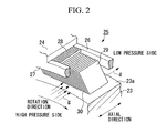
- FIG. 2 shows a perspective view of the leaf seal 25.
- the leaf seal 25 comprises a plurality of flexible thin plates 29 having a flexibility and a width in the axial direction of the rotary shaft 23 and sliding against the peripheral face 23a of the rotary shaft 23.
- the thin plates 29 have gaps 30 therebetween, and are secured by a brazing section 28 to the side of the casing 24.
- a plurality of the thin plates 29 are provided in the peripheral direction of the rotary shaft 23 so as to be laminated and capable of sealing the outer rim thereof.
- the thin plates 29 and the peripheral face peripheral face 23a of the rotary shaft 23 form an acute angle.
- a low pressure side side-plate 26 and a high pressure side side-plate 27 are provided on either side of the axial direction of the thin plates 29.
- Each thin plate 29 is the shape of a flat sheet having a predetermined width in the axial direction of the rotary shaft 23.
- the thin plates 29 are provided in a laminated arrangement in the peripheral direction of the rotary shaft 23.
- the outer peripheral side base is brazed at the brazing section 28 inside the casing 24, sealing the outer peripheral of the rotary shaft 23 so as to divided the surrounding space of the rotary shaft 23 into a high pressure side and a low pressure side.
- the high pressure side side-plate 27 is provided in the high pressure side
- the low pressure side side-plate 26 is provided in the low pressure side.
- the high pressure side side-plate 27 and the high pressure side side-plate 27 function as guide plates in the direction of pressure.
- the leaf seal 25 comprises a gas pressure adjusting mechanism which forms a gas pressure distribution 30a in which when gas pressure from the high pressure side toward the low pressure side, i.e., from the high pressure side side-plate 27 to the low pressure side side-plate 26 is applied to each thin plate 29, the gas pressure is highest at an angular section r1, which is at the tip side and on the side of the high pressure side side-plate 27, and gradually weakens as it approaches a diagonally opposite angular section r2.
- the gas pressure adjusting mechanism can adjust the gas pressure so that when the thin plates 29 are viewed in cross-section along an imaginary plane at a right-angle to the direction of the width of the thin plates 29 as shown in FIG. 3B, and the face of the thin plate which faces the rotary shaft 23 is deemed the bottom face 29b and the rear side is deemed the top face 29a, and gas pressure from the high pressure side toward the low pressure side, i.e., from the high pressure side side-plate 27 to the low pressure side side-plate 26 is applied to the thin plates 29, the gas pressure applied to the bottom face 29b is higher than the gas pressure applied to the top face 29a at a given point along the cross-sectional faces of the thin plates 29.
- This mechanism will be explained below in detail.
- the low pressure side gap 31 between each of the thin plates 29 and the low pressure side side-plate 26 is larger than the high pressure side gap 32 between each of the thin plates 29 and the high pressure side side-plate 27.
- the gas g which passes through the thin plates 29 in flowing from the high pressure side to the low pressure side, flows widely along the top face 29a and the bottom face 29b of each of the thin plates 29 toward the diagonal angle, and simultaneously, the low pressure region at the outer peripheral base increases.
- the gas g flowing from the high pressure side to the low pressure side flows between the peripheral face 23a of the rotary shaft 23 and the tips of the thin plates 29, and also flows along the top face 29a and bottom face 29b of the thin plates 29.
- the gas g flowing along the top face 29a and bottom face 29b of the thin plates 29 enters between the high pressure side side-plate 27 and the peripheral face 23a of the rotary shaft 23, and flows radially from r1 toward r2, whereby the low pressure region expands at the outer peripheral base. Therefore, as shown in FIG. 3B, the gas pressure distributions 30b and 30c, applied at a perpendicular to the top face 29a and bottom face 29b of the thin plates 29, increase nearer the tip section and decrease as they approach the outer peripheral base, producing triangular distribution.
- the shapes of the gas pressure distributions 30b and 30c at the top face 29a and bottom face 29b are substantially identical. However, since the thin plates 29 are arranged diagonally so as to form an acute angle with the peripheral face 23a of the rotary shaft 23, the relative positions of the gas pressure distributions 30b and 30c at the top face 29a and bottom face 29b deviate by a distance of s1. A comparison of the gas pressures against the top face 29a and the bottom face 29b at a predetermined point P along the line from the outer peripheral side to the tip side of the thin plates 29 shows that there is a difference between them.
- the thin plates 29 deform and rise up higher than the rotary shaft 23, acting in this direction.
- the outermost tip sections of the thin plates 29 are cut diagonally so that they touch the peripheral face 23a, there is no section corresponding to the bottom face 29b. Therefore, the reverse occurs at the section near the tips of the thin plates 29, and gas pressure is applied only to the top face 29a.
- this force is cancelled out by the pressure of gas flowing between the peripheral face 23a and the tips of the thin plates 29, which acts in the direction along which the tips of the thin plates 29 rise from the peripheral face 23a (Fc).
- the pressure load of the gas pressure applied to the each thin plate 29 is (Fb + Fc) > Fa, enabling the thin plates 29 to be deformed so as to rise up higher than the peripheral face 23a.
- the pressure adjusting mechanism uses the difference in pressure when gas pressure is applied from the high pressure side to achieve a state of non-contact between the thin plates 29 and the rotary shaft 23.
- a similar state of non-contact between the thin plates 29 and the rotary shaft 23 can be achieved by using the rotation of the rotary shaft 23.
- the thin plates 29 are designed so as to have a predetermined flexibility, determined on their thickness, in the axial direction of the rotary shaft 23.
- the thin plates 29 are installed inside the casing 24 with an acute angle between the peripheral face 23a of the rotary shaft 23 and the axial direction of the rotary shaft 23.
- each gap 30 can be regarded as approximately constant from the outer side of the rim to the inner side of the rim.
- the angle between the thin plates 29 and the peripheral face 23a of the rotary shaft 23 is made acute, and the pressure adjusting mechanism for applying a rising force to the thin plates 29 is provided, in which the low pressure side gap 31 between each of the thin plates 29 and the low pressure side side-plate 26 is larger than the high pressure side gap 32 between each of the thin plates 29 and the high pressure side side-plate 27.
- the section which is fixed to the casing 24 is much larger than when using conventional wires. Therefore, the thin plates 29 are securely fixed to the casing 24. Consequently, it is possible to prevent the thin plates 29 from becoming disconnected from the casing 24; this was a problem in a conventional brush seal, in which the wires became disconnected.
- the gaps 30 between the thin plates 29 can be arranged more tightly, and the gap between the tips of the thin plates 29 and the rotary shaft 23 can be made markedly smaller than in the case of a non-contacting labyrinth seal and the like.
- the amount of leakage can be reduced to approximately one-tenth of that in the labyrinth seal, whereby the performance of the gas turbine can be increased by approximately 10 %.
- the low pressure side side-plate 26 and the high pressure side side-plate 27 are arranged so that the low pressure side gap 31 is larger than the high pressure side gap 32, and whereby creating a difference in the pressure load against the thin plates 29 when pressure is applied thereto from the high pressure side, and causing the tips of the thin plates 29 to rise up.
- the following embodiments can, for example, be applied as modifications.
- a second embodiment of the present invention will be explained with reference to FIG. 4.
- the explanation will center on the characteristic parts, and parts which are identical to those in the first embodiment will not be explained further.
- FIG. 4 shows the leaf seal 25 which is equipped with another pressure adjusting mechanism for creating a difference in pressure load between the top face 29a and the bottom face 29b of the thin plates 29 when pressure has been applied from the high pressure side, causing the tips of the thin plates 29 to rise.
- the sizes of the side-plates 26 and 27 are adjusted so that the low pressure side side-plate length 33, which is the length of the low pressure side side-plate 26 in the radial direction of the rotary shaft 23, is shorter than the high pressure side side-plate length 34, which is the length of the high pressure side side-plate 27 in the radial direction of the rotary shaft 23.
- the gas g flows radially along the top face 29a and bottom face 29b of the thin plates 29 in the direction from r1 to r2. Therefore, as already mentioned, at a given position along the cross-sectional face perpendicular to the width of the thin plates 29, the distribution of gas pressure applied to the top face 29a and bottom face 29b of the thin plates 29 is made triangular, decreasing gradually from the tip side of the thin plates 29 toward the outer peripheral side base.
- the gas pressure distribution 30a of gas pressure applied at a perpendicular to the top face 29a and bottom face 29b of the thin plates 29 by the gas g, which passes through the gap 30, is such that the gas pressure is highest at the angular section r1, which is at the tip side and on the side of the high pressure side side-plate 27, and gradually weakens as it approaches the diagonally opposite angular section r2.
- the pressure distribution in the radial direction of the given cross-sectional face of the axial direction width of the thin plates 29 becomes gas pressure distributions 30b and 30c, as described in the first embodiment of FIG. 3B, and, since a difference in pressure load ((Fb + Fc) > Fa) is created between the thin plate bottom face 29b and the thin plate tip face 29c, the difference in pressure load acts as a force on the thin plates 29, making their tips rise upwards.
- the difference in pressure load on the thin plates 29 acts as a force in the direction which the tips of the thin plates 29 rise.
- the sizes of the side-plates 26 and 27 are adjusted so that the low pressure side side-plate length 33, which is the length of the low pressure side side-plate 26 in the radial direction of the rotary shaft 23 is shorter than the high pressure side side-plate length 34, which is the length of the high pressure side side-plate 27 in the radial direction of the rotary shaft 23.
- the low pressure side side-plate 26 may be omitted.
- FIGS. 5A and 5B A third embodiment of the present invention will be explained with reference to FIGS. 5A and 5B. The explanation will center on the characteristic parts, and parts which are identical to those in the first embodiment will not be explained further.
- flexible plates are provided, which are flexible in the axial direction of the rotary shaft 23 and are arranged on the high pressure side of the thin plates 29.
- FIGS. 5A and 5B show the leaf seal 25 which is equipped with another pressure adjusting mechanism for creating a difference in pressure load between the top face 29a and the bottom face 29b of the thin plates 29 when pressure has been applied from the high pressure side, and thereby causing the tips of the thin plates 29 to rise.
- FIG. 5A shows an example where the high pressure side side-plate 27 comprises a low-relief plate which is flexible in the axial direction of the rotary shaft 23, and
- FIG. 5B shows an example where a thin plate for minutely adjusting the high pressure side gap 35 is flexible in the axial direction of the rotary shaft 23 and is provided between the high pressure side side-plate 27 and the thin plates 29.
- the gas g which flows along the top face 29a and bottom face 29b of the thin plates 29, enters between the peripheral face 23a of the rotary shaft 23 and the high pressure side side-plate 27 and flows radially in the direction from r1 to r2, whereby the low pressure region at the outer peripheral base expands. Consequently, at a given position along the cross-sectional face perpendicular to the width of the thin plates 29, the distribution of gas pressure applied to the top and bottom faces of the thin plates 29 is made triangular, decreasing gradually from the tip side of the thin plates 29 toward the outer peripheral side base.
- the gas pressure distribution 30a which is applied at a perpendicular to the top face 29a and bottom face 29b of the thin plates 29 by the gas g which passes through the gap 30, is shaped so that the gas pressure is highest at angular section r1, on the tip side of the thin plates 29 and on the high pressure side side-plate 27, and gradually weakens as it approaches a diagonally opposite angular section r2.
- the pressure distribution in the radial direction of the cross-sectional face at a given position in the axial direction width of the thin plates 29 is that shown as gas pressure distributions 30b and 30c in the first embodiment of FIG. 3B, creating a pressure load difference (Fb + Fc) > Fa) between the top face 29a, and the bottom face 29b and the thin plate tip side 29c; this pressure load difference acts as a force in the direction which the tips of the thin plates 29 rise in.
- the pressure load difference in the thin plates 29 acts as a force which makes the tips of the thin plates 29 rise.
- this embodiment has merits of ease of assembly and inexpensive manufacturing cost for the same reasons as explained in the second embodiment, and the seal pressure enables the gap, that is, the gap between the thin plates 29 and the high pressure side side-plate 27 or the thin plate for minutely adjusting the high pressure side gap 35, to be automatically made with high precision.
- the gas pressure adjusting mechanism comprises slitted flexible plates, which are flexible in the direction of the rotary shaft 23 and are arranged on the high pressure side of the thin plates 29 and comprise slits at more than two places along the entire rim.
- FIG. 6A shows a case in which the high pressure side side-plate 27 is a slitted flexible plate 41 having slits 41a at more than two places on its entire rim and being flexible in the axial direction of the rotary shaft 23.
- FIG. 6B shows a case in which a low-relief plate having slits 42a at more than two places on its entire rim and being flexible in the axial direction of the rotary shaft 23 is provided in the gap between the high pressure side side-plate 27 and the thin plates 29 as a slitted flexible plate 42.
- the high pressure side gas pressure forces the high pressure side side-plate 27, or a thin plate for minutely adjusting the high pressure side gap 42, to bend in the axial direction of the rotary shaft 23, enabling the gap between the high pressure side side-plate 27 and the thin plates 29 to be kept small.
- the gas g which flows along the top face 29a and bottom face 29b of the thin plates 29, enters between the peripheral face 23a of the rotary shaft 23 and the high pressure side side-plate 27, and flows radially in the direction from r1 to r2, whereby the low pressure region at the outer peripheral base expands.
- the distribution of gas pressure applied to the top and bottom faces of the thin plates 29 is made triangular, decreasing gradually from the tip side of the thin plates 29 toward the outer peripheral side base.
- the gas pressure distribution 30a which is applied at a perpendicular to the top face 29a and bottom face 29b of the thin plates 29 by the gas g which passes through the gap 30, is shaped so that the gas pressure is highest at angular section r1, on the tip side of the thin plates 29 and on the high pressure side side-plate 27, and gradually weakens as it approaches a diagonally opposite angular section r2.
- the pressure distribution in the radial direction of the cross-sectional face at a given position in the axial direction width of the thin plates 29 is that shown as gas pressure distributions 30b and 30c in the first embodiment of FIG. 3B, creating a pressure load difference (Fb + Fc) > Fa) between the top face 29a, and the bottom face 29b and the thin plate tip side 29c; this pressure load difference acts as a force in the direction which the tips of the thin plates 29 rise in.
- the pressure load difference in the thin plates 29 acts as a force which makes the tips of the thin plates 29 rise.
- this embodiment has merits of ease of assembly and inexpensive manufacturing cost for the same reasons as explained in the second embodiment, and the seal pressure enables the gap, that is, the gap between the thin plates 29 and the slitted flexible plates 41 and 42, to be automatically made with high precision.
- This embodiment is superior to the first embodiment with regard to ease of assembly and manufacturing cost, and, in addition, is superior to the third embodiment in that minute adjustment of the gap, that is, the gap between the thin plates 29 and the slitted flexible plates 41 and 42, is possible due to shape of the slits 41a and 42a.
- the gas pressure adjusting mechanism comprises a plurality of draft holes, provided through the low pressure side side-plate 26 in the axial direction of the rotary shaft 23.
- FIG. 7 shows a cross-section view of the leaf seal 25 from the cross-section which passes through the axial line of the rotary shaft 23; reference numeral 26a represents a draft hole.
- a porous material can be used as the low pressure side side-plate 26.
- the gas pressure distribution which is applied at a perpendicular to the top face 29a and bottom face 29b of the thin plates 29 by the gas g which passes through the gap 30, becomes the isobaric line of distribution shown by the pressure distribution 30a in the first embodiment. That is, the gas pressure is highest at angular section r1, on the tip side of the thin plates 29 and on the high pressure side side-plate 27, and gradually weakens as it approaches a diagonally opposite angular section r2.
- the pressure distribution in the radial direction of the cross-sectional face at a given position in the axial direction width of the thin plates 29 is that shown as gas pressure distributions 30b and 30c in the first embodiment of FIG. 3B, creating a pressure load difference (Fb + Fc) > Fa) between the top face 29a, and the bottom face 29b and the thin plate tip side 29c; this pressure load difference acts as a force in the direction which the tips of the thin plates 29 rise in.
- the pressure load difference in the thin plates 29 acts as a force which makes the tips of the thin plates 29 rise. Moreover, since all that is needed is to provide the holes for the draft holes 26a, assembly is easy and manufacturing cost is reduced. In addition, complex pressure distribution can be achieved by adjusting the arrangement and size of the holes.
- the exposed section of the thin plates 29 is smaller than in the second embodiment, reducing deformation of the thin plates due to contact and the like at the time of assembly.
- FIGS. 8A and 8B a sixth embodiment of the present invention will be explained with reference to FIGS. 8A and 8B.
- the explanation will center on the characteristic parts, and parts which are identical to those in the first embodiment will not be explained further.
- a gap size adjusting mechanism for ensuring that the low pressure side gap 31 is always larger than the high pressure side gap 32.
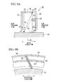
- FIG. 8A is a cross-sectional view of the leaf seal 25 from the cross-sectional face which passes the axial line of the rotary shaft 23, and FIG. 8B is a cross-sectional view taken along the line C-C in FIG. 8A.
- the gap size adjusting mechanism comprises a first step section 50, provided between the low pressure side side-plate 26 and the thin plates 29, for supporting the thin plate 29 and maintaining the size of the low pressure side gap 31 between the low pressure side side-plate 26 and the thin plate 29 when the thin plate 29 attempts to move toward the low pressure side side-plate 26.
- the first step section 50 when viewed along the cross-sectional face which passes the axial line of the rotary shaft 23, the first step section 50 is provided on the side of the low pressure side side-plate 26 and protrudes toward the thin plates 29 side.
- the first step section 50 when viewed from the cross-sectional face which crosses the axial line of the rotary shaft 23 at a perpendicular, the first step section 50 has a ring shape which runs along the ring low pressure side side-plate 26 and continues across the entire rim of the rotary shaft 23.
- the first step section 50 may be a separate component from the low pressure side side-plate 26 or may be provided together with the low pressure side side-plate 26.
- the size of the low pressure side gap 31 can be prevented from dropping below t2 by restricting deviation and deformation of the thin plates 29, enabling a predetermined gap to be maintained easily.
- the first step section 50 supports the thin plate 29 and stops the thin plate 29 from moving toward the low pressure side side-plate 26 side. Therefore, even when assembly errors are made at the time of assembling the shaft seal, and when the thin plates 29 suffer deformation and the like due to the pressure of gas flowing from the high pressure side to the low pressure side during operation, the gap between the thin plates 29 and the low pressure side side-plate 26 can be maintained at the predetermined distance of t2.
- a seventh embodiment of the present invention will be explained with reference to FIGS. 9A and 9B.
- This embodiment corresponds to a modification of the sixth embodiment, and the explanation will center on the points of difference with the sixth embodiment; parts which are identical to those in the sixth embodiment will not be explained further.
- FIG. 9A is a cross-sectional view of the leaf seal 25 from the cross-sectional face which passes the axial line of the rotary shaft 23, and FIG. 9B is a cross-sectional view taken along the line D-D of FIG. 9A.
- this embodiment is characterized in that ventilation holes 51 are provided in the ring first step section 50 described in the sixth embodiment, and form a space which joins the inner peripheral side to the outer peripheral side. As shown in FIG. 9B, a plurality of the ventilation holes 51 are provided with equal distances therebetween.
- the first step section 50 Providing the plurality of ventilation holes 51 along the first step section 50 in this way reduces resistance to the flow of gas between the rotary shaft radial direction inner peripheral side and the rotary shaft radial direction outer peripheral side, with the first step section 50 as a boundary, in the gap space between the thin plate 29 and the low pressure side side-plate 26. Consequently, the first step section 50 continues to support the thin plates 29, while achieving pressure distribution in the radial direction of the rotary shaft just as though the first step section 50 did not exist.
- the gas pressure distribution over a wide range (the area represented by a solid line arrow R1 in FIG. 9A) can be made such that the gas pressure against the top and bottom faces of the thin plates 29 is highest at an angular section r1 at the tip side opposite to the rotary shaft 23 and on the side of the high pressure side side-plate 27, and gradually weakens as it approaches the diagonally opposite angular section r2, avoiding gas distribution over a narrow range such as that shown by the double-dotted line arrow R2 in FIG. 9A.
- the pressure difference on the top and bottom faces of the thin plates 29 can be reliably achieved throughout a wide area, making it possible to reliably adjust the gas pressure so that the thin plates 29 rise up higher than the peripheral face 23a of the rotary shaft 23.
- FIGS. 10A to 10C An eighth embodiment of this invention will be explained with reference to FIGS. 10A to 10C.
- This embodiment corresponds to a modification of the sixth embodiment, and the explanation will center on the points of difference with the sixth embodiment; parts which are identical to those in the sixth embodiment will not be explained further.
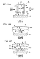
- FIG. 10A is a cross-sectional view of the leaf seal 25 from the cross-sectional face which passes the axial line of the rotary shaft 23, and FIGS. 10B and 10C are cross-sectional views taken along the line E-E of FIG. 10A.
- this embodiment is characterized in having a step second section 50A comprising a plurality of ring divided plates 50a, provided intermittently with equal intervals G therebetween along the low pressure side side-plate 26 so as to form a ring around the rotary shaft 23, the second step section 50A being secured to the low pressure side side-plate 26.
- the second step section 50A when viewed from the cross-sectional face which passes the axial line of the rotary shaft 23, the second step section 50A is provided on the low pressure side side-plate 26 so as to protrude toward the thin plates 29 side.
- the second step section 50A comprising the ring divided plates 50a may be a separate component from the low pressure side side-plate 26 or may be provided together with the low pressure side side-plate 26.
- the intervals G fulfil the function of the ventilation holes 51 of the seventh embodiment, thereby reducing resistance to the flow of gas between the rotary shaft radial direction inner peripheral side and the rotary shaft radial direction outer peripheral side, with the second step section 50A as a boundary, in the gap space between the thin plate 29 and the low pressure side side-plate 26. Consequently, the thin plates 29 are supported by the second step section 50A while pressure distribution is achieved in the radial direction of the rotary shaft just as though the second step section 50A did not exist.
- the gas pressure distribution over a wide range (the area represented by a solid line arrow R1 in FIG. 10A) can be made such that the gas pressure against the top and bottom faces of the thin plates 29 is highest at an angular section r1 at the tip side opposite to the rotary shaft 23 and on the side of the high pressure side side-plate 27, and gradually weakens as it approaches the diagonally opposite angular section r2, avoiding gas distribution over a narrow range such as that shown by the double-dotted line arrow R2 in FIG. 10A.
- the pressure difference on the top and bottom faces of the thin plates 29 can be reliably achieved throughout a wide area, making it possible to reliably adjust the gas pressure so that the thin plates 29 rise up higher than the peripheral face 23a of the rotary shaft 23.
- two of the second step section 50A i.e., two steps can of course be provided concentrically around the rotary shaft 23; three or more may be provided, which is not shown.
- FIGS. 11A to 11C A ninth embodiment of this invention will be explained with reference to FIGS. 11A to 11C.
- This embodiment corresponds to a modification of the sixth embodiment, and the explanation will center on the points of difference with the sixth embodiment; parts which are identical to those in the sixth embodiment will not be explained further.
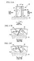
- FIG. 11A is a cross-sectional view of the leaf seal 25 from the cross-sectional face which passes the axial line of the rotary shaft 23, and FIGS. 11B and 11C are cross-sectional views taken along the line F-F of FIG. 11A.
- this embodiment is characterized in having a third step section 50B which comprises a plurality of spiral plates 50b, which, when the low pressure side side-plate 26 is viewed from the thin plates 29 side, are provided spirally from the rotary shaft radial direction inner peripheral side to the rotary shaft radial direction outer peripheral side of the low pressure side side-plate 26 with equal intervals G therebetween; the third step section 50B is secured to the low pressure side side-plate 26.
- the third step section 50B is provided on the low pressure side side-plate 26 side so as to protrude toward the thin plates 29.
- the spiral plates 50b are secured to the low pressure side side-plate 26 at a gradient which intersects with the thin plates 29 in a cross arrangement.
- the third step section 50B comprising the spiral plates 50b may be a separate component from the low pressure side side-plate 26 or may be provided together with the low pressure side side-plate 26.
- FIG. 11C shows an example of one modification of this embodiment, wherein, when the low pressure side side-plate 26 is viewed from the thin plates 29 side, the spiral plates 50b are secured to the low pressure side side-plate 26 in the same direction as the thin plates 29 but at a different gradient angle, i.e. a different gradient angle with the peripheral face 23a of the rotary shaft 23.
- the cross arrangement of FIG. 11B is more preferable, since this arrangement enables a greater number of thin plates 29 to be supported by each spiral plate 50b.
- the intervals G fulfil the function of the ventilation holes 51 of the seventh embodiment, thereby reducing resistance to the flow of gas between the rotary shaft radial direction inner peripheral side and the rotary shaft radial direction outer peripheral side, with the third step section 50B as a boundary, in the gap space between the thin plate 29 and the low pressure side side-plate 26. Consequently, the thin plates 29 are supported by the third step section 50B while pressure distribution is achieved in the radial direction of the rotary shaft just as though the third step section 50B did not exist.
- the gas pressure distribution over a wide range (the area represented by a solid line arrow R1 in FIG 11A) can be made such that the gas pressure against the top and bottom faces of the thin plates 29 is highest at an angular section r1 at the tip side opposite to the rotary shaft 23 and on the side of the high pressure side side-plate 27, and gradually weakens as it approaches the diagonally opposite angular section r2, avoiding gas distribution over a narrow range.
- the pressure difference on the top and bottom faces of the thin plates 29 can be reliably achieved throughout a wide area, making it possible to reliably adjust the gas pressure so that the thin plates 29 rise up higher than the peripheral face 23a of the rotary shaft 23.
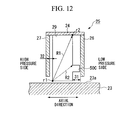
- a tenth embodiment of this invention will be explained with reference to FIG. 12.
- This embodiment corresponds to a modification of the sixth embodiment, and the explanation will center on the points of difference with the sixth embodiment; parts which are identical to those in the sixth embodiment will not be explained further.
- FIG. 12 a cross-sectional view of the leaf seal 25 from the cross-sectional face which passes the axial line of the rotary shaft 23.
- this embodiment is characterized in having a fourth step section 50C which is provided to each of the thin plates 29 so as to protrude toward the low pressure side side-plate 26.
- the fourth step sections 50C are protruding sections, formed integrally with the thin plates 29, and the gaps between them are the same size as the gaps between the thin plates 29.
- the gaps between the fourth step sections 50C fulfill the function of the ventilation holes 51 of the seventh embodiment, thereby reducing resistance to the flow of gas between the rotary shaft radial direction inner peripheral side and the rotary shaft radial direction outer peripheral side, with the fourth step section 50C as a boundary, in the gap space between the thin plate 29 and the low pressure side side-plate 26. Consequently, the thin plates 29 are supported by the fourth step sections 50C while pressure distribution is achieved in the radial direction of the rotary shaft just as though the fourth step sections 50C did not exist.
- the gas pressure distribution wherein the gas pressure against the top and bottom faces of the thin plates 29 is highest at an angular section r1 at the tip side opposite to the rotary shaft 23 and on the side of the high pressure side side-plate 27, and gradually weakens as it approaches the diagonally opposite angular section r2, can be spread over a wide range (the area represented by a solid line arrow R1 in FIG. 12), thereby avoiding gas distribution over a narrow range, such as that shown, for example, by the double-dotted line arrow R2 in FIG. 12.
- the pressure difference on the top and bottom faces of the thin plates 29 can be reliably achieved throughout a wide area, making it possible to reliably adjust the gas pressure so that the thin plates 29 rise up higher than the peripheral face 23a of the rotary shaft 23.
- this embodiment has an advantage of low manufacturing cost.
- FIG. 13 An eleventh embodiment of this invention will be explained with reference to FIG. 13.
- This embodiment corresponds to a modification of the sixth embodiment, and the explanation will center on the points of difference with the sixth embodiment; parts which are identical to those in the sixth embodiment will not be explained further.
- FIG. 13 is a cross-sectional view of the leaf seal 25 from the cross-sectional face which passes the axial line of the rotary shaft 23.
- this embodiment is characterized in that the first step section 50 in a ring shape described in the sixth embodiment continues along the radial direction of the low pressure side side-plate 26 to the casing 24. That is, when viewed in cross-section as in FIG. 13, the first step section 50 of this embodiment is provided widely so as to continue to the base of the low pressure side side-plate 26, which is the section connecting the casing 24 and the low pressure side side-plate 26. During normal operation, the face of the first step section 50 which is facing the thin plates 29 does not directly contact the thin plates 29, and there is a small gap between the two.
- the size of the low pressure side gap 31 can be prevented from dropping below t2 by restricting deviation and deformation of the thin plates 29, enabling a predetermined gap to be maintained easily.
- the first step section 50 supports the thin plate 29 and stops it from moving nearer. Therefore, even when assembly errors are made at the time of assembling the shaft seal, and when the thin plates suffer deformation and the like due to the pressure of gas flowing from the high pressure side to the low pressure side during operation, the gap 31 between the thin plates 29 and the low pressure side side-plate 26 can be kept at the predetermined size t2.
- the gaps 31 and 32 between the thin plates 29 and the side-plates 26 and 27 can be kept at the predetermined sizes, even when there is some pressure fluctuation between the high pressure side and low pressure side, the sizes of the gaps are unlikely to change. Therefore, the area over which the seal pressure is applied can be enlarged. Further, since there is a small gap between the first step section 50 and the thin plates 29, the tolerances of the gaps between the high pressure side side-plate 27 and 26 and the thin plates 29 can be designed more freely, enabling processing cost to be reduced.
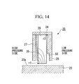
- a twelfth embodiment of this invention will be explained with reference to FIG. 14.
- This embodiment corresponds to a modification of the eleventh embodiment, and the explanation will center on the points of difference with the eleventh embodiment; parts which are identical to those in the eleventh embodiment will not be explained further.
- FIG. 14 is a cross-sectional view of the leaf seal 25 from the cross-sectional face which passes the axial line of the rotary shaft 23.
- the thin plate for minutely adjusting the high pressure side gap 35 of the third embodiment described above in FIG. 5B is provided between the high pressure side side-plate 27 and the thin plates 29.
- the distribution of gas pressure against the top and bottom faces of the thin plates 29 is shaped so that the gas pressure is highest at the angular section r1 on the tip side of the thin plates 29 and on the high pressure side side-plate 27, and gradually weakens as it approaches the diagonally opposite angular section r2.
- a thirteenth embodiment of this invention will be explained with reference to FIG. 15.
- This embodiment corresponds to a modification of the twelfth embodiment, and the explanation will center on the points of difference with the twelfth embodiment; parts which are identical to those in the twelfth embodiment will not be explained further.
- FIG. 15 is a cross-sectional view of the leaf seal 25 from the cross-sectional face which passes the axial line of the rotary shaft 23.
- a lead-pressure hole 100 is provided in the high pressure side side-plate 27 of the twelfth embodiment and leads in the axial direction of the rotary shaft 23; a plurality of the lead-pressure holes 100 are provided in the perimeter direction.
- part of the gas at the high pressure side can be applied to the thin plate for minutely adjusting the high pressure side gap 35 by passing via the lead-pressure holes 100 and the high pressure side side-plate 27. Therefore, the thin plate for minutely adjusting the high pressure side gap 35 can be more effectively bent. Consequently, the effects of the twelfth embodiment can be more reliably obtained.
- the leaf seal i.e., the shaft seal of the first to the thirteenth embodiments described above apply not only in a conventional gas turbine which obtains dynamic force from the rotation of a turbine axis by using combustible gas, but also to a gas turbine engine for air plane use, and the like.
- the gas turbine of the present invention can also be applied in fluid machines such as a vapor turbine which uses steam vapor.
- shaft seal of this invention can also be applied in various types of fluid machines, such as a gas turbine, a gas turbine engine, a vapor turbine, and the like.
- the leaf seal 25 and the gas turbine comprising the leaf seal 25 of the third and fourth embodiments may comprise combinations of the gap size adjusting mechanism 50, 50A, 50B, and 50C described above. In this case, the same effects can, of course, be obtained by using the gap size adjusting mechanism 50, 50A, 50B, and 50C.
Landscapes
- Engineering & Computer Science (AREA)
- General Engineering & Computer Science (AREA)
- Mechanical Engineering (AREA)
- Sealing Devices (AREA)
- Turbine Rotor Nozzle Sealing (AREA)
- Sealing Using Fluids, Sealing Without Contact, And Removal Of Oil (AREA)
Abstract
Description
In order to achieve the above objects, the present invention provide another shaft seal comprising: a plurality of flexible thin plates having width in the axial direction of a rotary shaft, tips thereof sliding against a peripheral face of the rotary shaft and outer peripheral bases thereof being secured to a casing side, and gaps provided therebetween, the thin plates being laminated in the peripheral direction of the rotary shaft, enabling the outer periphery of the rotary shaft to be sealed, an acute angle being formed between the thin plates and the peripheral face of the rotary shaft; wherein a gas ventilation space for allowing gas to pass from the high pressure side to the low pressure side, provided in the low pressure side of the thin plates in the axial direction.
Claims (19)
- A shaft seal comprising:wherein it further comprises a gas pressure adjusting mechanism, which when said thin plates are viewed cross-sectionally along an imaginary plane which is perpendicular to the direction of their width, the face of each thin plate which faces the rotary shaft is deemed a bottom face and the rear side is deemed a top face, and gas pressure from said high pressure side side-plate to said low pressure side side-plate is applied to said thin plates, ensures that the gas pressure applied to said bottom faces is higher than the gas pressure applied to said top faces at a given point along said cross-sectional face of said thin plates.a plurality of flexible thin plates having width in the axial direction of a rotary shaft, tips thereof sliding against a peripheral face of said rotary shaft, and outer peripheral bases thereof being secured to a casing side maintaining a gap therebetween, said thin plates being laminated in the peripheral direction of said rotary shaft, enabling the outer periphery of said rotary shaft to be sealed, an acute angle being formed between the thin plates and the peripheral face of said rotary shaft; anda low pressure side side-plate and a high pressure side side-plate which are provided on both sides of said thin plates in the axial direction of said rotary shaft,
- A shaft seal according to claim 1, wherein said gas pressure adjusting mechanism makes a gas pressure distribution such that the gas pressure is highest at the angular section, which is positioned at said tip side and on the side of said high pressure side side-plate, and gradually weakens as it approaches a diagonally opposing angle.
- A shaft seal according to claim 1, wherein said gas pressure adjusting mechanism comprises said low pressure side side-plate and said high pressure side side-plate, which are positioned so that the size of a low pressure side gap between said thin plates and said low pressure side side-plate is larger than a high pressure side gap between said thin plates and said high pressure side side-plate.
- A shaft seal according to claim 1, wherein said gas pressure adjusting mechanism comprises said high pressure side side-plate, and said low pressure side side-plate of which the length in the radial direction of said rotary shaft is shorter than the length of said high pressure side side-plate in the radial direction of said rotary shaft.
- A shaft seal according to claim 1, wherein said gas pressure adjusting mechanism comprises a flexible plate, which is flexible in the axial direction of said rotary shaft and is arranged on the high pressure side of said thin plates.
- A shaft seal according to claim 1, wherein said gas pressure adjusting mechanism comprises slitted flexible plates, which are flexible in the axial direction of said rotary shaft, are arranged on the high pressure side of said thin plates, and comprise slits at more than two places along the entire rim thereof.
- A shaft seal according to claim 1, wherein said gas pressure adjusting mechanism comprises a low pressure side side-plate in which a plurality of draft holes passing through said low pressure side side-plate in the axial direction of said rotary shaft.
- A shaft seal comprising:wherein a gas ventilation space for allowing gas to pass from the high pressure side to the low pressure side, provided in the low pressure side of said thin plates in the axial direction.a plurality of flexible thin plates having width in the axial direction of a rotary shaft, tips thereof sliding against a peripheral face of said rotary shaft and outer peripheral bases thereof being secured to a casing side, and gaps provided therebetween, the thin plates being laminated in the peripheral direction of said rotary shaft, enabling the outer periphery of said rotary shaft to be sealed, an acute angle being formed between the thin plates and the peripheral face of said rotary shaft;
- A shaft seal according claim 3, 5 or 6, wherein it further comprises a gap size adjusting mechanism, which is provided between the low pressure side side-plate and the thin plates, for supporting the thin plates and maintaining the size of the gap between said low pressure side side-plate and the thin plates when the thin plates attempt to move toward the low pressure side side-plate.
- A shaft seal as described in claim 9, wherein said gap size adjusting mechanism comprises a first step section, which is provided on the side of said low pressure side side-plate so as to protrude toward the thin plates side; and
said first step section forms a ring which runs along the low pressure side side-plate around said rotary shaft. - A shaft seal according to claim 10, wherein said first step section comprises ventilation holes for forming a space which joins the rotary shaft radial direction inner peripheral side and the rotary shaft radial direction outer peripheral side between said thin plate and said low pressure side side-plate.
- A shaft seal according to claim 9, wherein said gap adjusting mechanism comprises a second step section, which is provided on the side of said low pressure side side-plate so as to protrude toward the thin plates side; and
said second step section comprising a plurality of ring divided plates, provided intermittently with equal intervals therebetween along said low pressure side side-plate so as to form a ring around said rotary shaft. - A shaft seal according to claim 10, wherein a plurality of said first step section are provided concentrically around said rotary shaft.
- A shaft seal according to claim 12, wherein a plurality of said second step section are provided concentrically around said rotary shaft.
- A shaft seal according to claim 9, wherein said gap adjusting mechanism comprises a third step section, which is provided on the side of said low pressure side side-plate so as to protrude toward the thin plates side; and
said third step section comprising a plurality of spiral plates, which, when the low pressure side side-plate is viewed from the thin plates side, are provided spirally from the rotary shaft radial direction inner peripheral side to the rotary shaft radial direction outer peripheral side of said low pressure side side-plate with equal interval therebetween. - A shaft seal according to claim 10, wherein said first step section is provided along the radial direction of said low pressure side side-plate to the position of said casing.
- A shaft seal according to claim 16, wherein said first step section comprises pressure-leading holes passing through said high pressure side side-plate in the axial direction of said rotary shaft.
- A shaft seal according to claim 9, wherein said gap adjusting mechanism comprises a fourth step section, which is provided with the side of said thin plates so as to protrude toward said low pressure side side-plate.
- A gas turbine which leads gas of high temperature and high pressure into a casing and blows it against moving blades, which are rotatably supported inside the casing, thereby converting the thermal energy of said gas to mechanical rotation energy and generating dynamic force,
wherein said gas turbine comprising said shaft seal according to any one of claims 1 to 18.
Applications Claiming Priority (2)
| Application Number | Priority Date | Filing Date | Title |
|---|---|---|---|
| JP2001032132 | 2001-02-08 | ||
| JP2001032132A JP3616016B2 (en) | 2000-04-28 | 2001-02-08 | Shaft seal mechanism and gas turbine |
Publications (3)
| Publication Number | Publication Date |
|---|---|
| EP1231416A2 true EP1231416A2 (en) | 2002-08-14 |
| EP1231416A3 EP1231416A3 (en) | 2004-07-14 |
| EP1231416B1 EP1231416B1 (en) | 2006-07-19 |
Family
ID=18896112
Family Applications (1)
| Application Number | Title | Priority Date | Filing Date |
|---|---|---|---|
| EP01125628A Expired - Lifetime EP1231416B1 (en) | 2001-02-08 | 2001-10-26 | Shaft seal and gas turbine |
Country Status (4)
| Country | Link |
|---|---|
| US (1) | US7066468B2 (en) |
| EP (1) | EP1231416B1 (en) |
| CA (1) | CA2359933C (en) |
| DE (1) | DE60121539T8 (en) |
Cited By (17)
| Publication number | Priority date | Publication date | Assignee | Title |
|---|---|---|---|---|
| WO2004036094A1 (en) * | 2002-10-18 | 2004-04-29 | Alstom Technology Ltd. | Sealing device |
| EP1302708A3 (en) * | 2001-10-09 | 2004-05-12 | Mitsubishi Heavy Industries, Ltd. | Shaft seal mechanism and turbine |
| WO2004088180A3 (en) * | 2003-03-29 | 2005-03-24 | Rolls Royce Plc | A seal arrangement |
| EP1626210A1 (en) * | 2004-08-10 | 2006-02-15 | Mitsubishi Heavy Industries, Ltd. | Shaft sealing mechanism, structure for mounting shaft sealing mechanism on stator, and turbine |
| WO2006016098A1 (en) * | 2004-08-07 | 2006-02-16 | Rolls-Royce Plc | A leaf seal arrangement |
| FR2915549A1 (en) * | 2007-04-30 | 2008-10-31 | Gen Electric | METHODS AND DEVICES FOR FACILITATING SEALING IN ROTATING MACHINES. |
| FR2915548A1 (en) * | 2007-04-30 | 2008-10-31 | Gen Electric | METHODS AND DEVICES FOR FACILITATING SEALING IN ROTATING MACHINES. |
| DE102004047206B4 (en) * | 2004-09-29 | 2009-09-17 | Mtu Aero Engines Gmbh | sealing arrangement |
| EP2105640A1 (en) | 2008-03-28 | 2009-09-30 | ALSTOM Technology Ltd | Leaf seal for turbomachine |
| EP2141392A3 (en) * | 2008-06-30 | 2010-01-27 | Rolls-Royce plc | A seal arrangement |
| DE102008055736A1 (en) * | 2008-11-04 | 2010-05-12 | Siemens Aktiengesellschaft | Brush seal for a turbomachine and turbo machine with a brush ring seal assembly |
| EP1479951A3 (en) * | 2003-05-21 | 2011-11-16 | Mitsubishi Heavy Industries, Ltd. | Shaft seal |
| CN102362107A (en) * | 2009-06-16 | 2012-02-22 | 三菱重工业株式会社 | Shaft seal and rotary machine with same |
| EP2604894A1 (en) * | 2011-12-14 | 2013-06-19 | Rolls-Royce plc | Improved leaf seal |
| EP2626603A1 (en) * | 2012-02-08 | 2013-08-14 | Rolls-Royce plc | Leaf seal |
| US9057444B2 (en) | 2012-05-31 | 2015-06-16 | Rolls-Royce Plc | Leaf seal |
| EP3418500A1 (en) * | 2017-06-21 | 2018-12-26 | MTU Aero Engines GmbH | Sealing assembly for a turbo engine |
Families Citing this family (40)
| Publication number | Priority date | Publication date | Assignee | Title |
|---|---|---|---|---|
| JP3993536B2 (en) * | 2003-06-20 | 2007-10-17 | 三菱重工業株式会社 | Manufacturing method of shaft seal, shaft seal, shaft seal member, and rotary machine using shaft seal |
| US7413194B2 (en) * | 2004-10-28 | 2008-08-19 | Rolls-Royce Plc | Pressure balanced annular seal |
| DE102004059858A1 (en) * | 2004-12-11 | 2006-06-29 | Alstom Technology Ltd | Lamella seal, in particular for a gas turbine |
| EP1707856A1 (en) * | 2005-04-01 | 2006-10-04 | Cross Manufacturing Company (1938) Limited | Brush seals |
| JP3970298B2 (en) * | 2005-11-10 | 2007-09-05 | 三菱重工業株式会社 | Shaft seal mechanism |
| US20070114727A1 (en) * | 2005-11-21 | 2007-05-24 | General Electric Company | Seal member, assembly and method |
| GB0613630D0 (en) * | 2006-07-10 | 2006-08-16 | Rolls Royce Plc | A seal arrangement |
| US8382119B2 (en) | 2006-08-15 | 2013-02-26 | General Electric Company | Compliant plate seals for turbomachinery |
| US7419164B2 (en) * | 2006-08-15 | 2008-09-02 | General Electric Company | Compliant plate seals for turbomachinery |
| US7703774B2 (en) * | 2006-09-12 | 2010-04-27 | General Electric Company | Shaft seal using shingle members |
| US20080107525A1 (en) * | 2006-11-02 | 2008-05-08 | General Electric Company | Shaft seal formed of tapered compliant plate members |
| GB0705671D0 (en) * | 2007-03-24 | 2007-05-02 | Cross Mfg Co 1938 Ltd | A seal |
| US8205889B2 (en) * | 2007-11-27 | 2012-06-26 | General Electric Company | Methods and apparatus to facilitate sealing in rotary machines |
| US7909335B2 (en) * | 2008-02-04 | 2011-03-22 | General Electric Company | Retractable compliant plate seals |
| US20100143102A1 (en) * | 2008-02-18 | 2010-06-10 | General Electric Company | Compliant plate seal with self-correcting behavior |
| US20110309585A1 (en) * | 2009-06-16 | 2011-12-22 | Hidekazu Uehara | Shaft seal device |
| US8333544B1 (en) | 2009-08-14 | 2012-12-18 | Florida Turbine Technologies, Inc. | Card seal for a turbomachine |
| US8152462B1 (en) | 2009-08-19 | 2012-04-10 | Florida Turbine Technologies, Inc. | Card seal with conical flexible seal |
| GB0919708D0 (en) * | 2009-11-11 | 2009-12-30 | Alstom Technology Ltd | Leaf seal |
| JP5398651B2 (en) * | 2010-06-24 | 2014-01-29 | 三菱重工業株式会社 | Shaft sealing mechanism and rotating machine equipped with the same |
| US9206904B2 (en) * | 2010-07-08 | 2015-12-08 | Siemens Energy, Inc. | Seal including flexible seal strips |
| US8690158B2 (en) | 2010-07-08 | 2014-04-08 | Siemens Energy, Inc. | Axially angled annular seals |
| US8382120B2 (en) * | 2010-08-31 | 2013-02-26 | General Electric Company | Method and apparatus for compliant plate seals |
| JP5631155B2 (en) | 2010-10-27 | 2014-11-26 | 三菱重工業株式会社 | Shaft seal mechanism and rotary machine equipped with the same |
| US8459653B2 (en) * | 2010-11-05 | 2013-06-11 | General Electric Company | Seal assembly segment joints |
| JP5693292B2 (en) * | 2011-02-25 | 2015-04-01 | 三菱重工業株式会社 | Shaft seal mechanism |
| JP5931450B2 (en) * | 2012-01-13 | 2016-06-08 | 三菱重工業株式会社 | Shaft seal device and rotary machine equipped with the same |
| JP6012505B2 (en) | 2013-02-22 | 2016-10-25 | 三菱重工業株式会社 | Shaft seal device and rotary machine |
| GB201311610D0 (en) * | 2013-06-28 | 2013-08-14 | Rolls Royce Plc | A Leaf Seal |
| GB201311607D0 (en) | 2013-06-28 | 2013-08-14 | Rolls Royce Plc | A leaf seal |
| GB201311611D0 (en) | 2013-06-28 | 2013-08-14 | Rolls Royce Plc | A Brush Seal |
| GB201312766D0 (en) * | 2013-07-19 | 2013-08-28 | Rolls Royce Plc | A leaf seal |
| FR3018109B1 (en) * | 2014-02-28 | 2016-05-06 | Snecma | REDUCING THE FLOW RATE OF A BRUSHED JOINT BY FLEXIBLE GEOMETRIC OBSTRUCTION |
| US20150285259A1 (en) * | 2014-04-05 | 2015-10-08 | Arthur John Wennerstrom | Filament-Wound Tip-Shrouded Axial Compressor or Fan Rotor System |
| DE102014213044B3 (en) * | 2014-07-04 | 2015-08-13 | MTU Aero Engines AG | brush seal |
| JP6245762B2 (en) * | 2014-12-16 | 2017-12-13 | 三菱日立パワーシステムズ株式会社 | Shaft seal mechanism |
| JP6270053B2 (en) * | 2014-12-16 | 2018-01-31 | 三菱日立パワーシステムズ株式会社 | Shaft seal mechanism |
| JP6675262B2 (en) * | 2016-05-09 | 2020-04-01 | 三菱日立パワーシステムズ株式会社 | Seal segment and rotating machine |
| JP6631837B2 (en) * | 2016-05-09 | 2020-01-15 | 三菱日立パワーシステムズ株式会社 | Seal segment and rotating machine |
| US12247490B2 (en) | 2022-03-04 | 2025-03-11 | Mitsubishi Heavy Industries, Ltd. | Shaft sealing device and rotary machine |
Family Cites Families (15)
| Publication number | Priority date | Publication date | Assignee | Title |
|---|---|---|---|---|
| GB8907695D0 (en) | 1989-04-05 | 1989-05-17 | Cross Mfg Co | Seals |
| FR2650048B1 (en) * | 1989-07-21 | 1992-05-07 | Alsthom Gec | SEALING FOR ROTARY SHAFT |
| US5031922A (en) * | 1989-12-21 | 1991-07-16 | Allied-Signal Inc. | Bidirectional finger seal |
| US5042823A (en) * | 1989-12-21 | 1991-08-27 | Allied-Signal Inc. | Laminated finger seal |
| US5054823A (en) * | 1990-02-05 | 1991-10-08 | Ductmate Industries, Inc. | Flange type duct connector |
| US5568931A (en) * | 1992-08-20 | 1996-10-29 | General Electric Company | Brush seal |
| DE4403605C2 (en) | 1994-02-05 | 1995-11-09 | Mtu Muenchen Gmbh | Gap seal between two mutually movable components |
| US5884918A (en) * | 1996-10-04 | 1999-03-23 | Eg&G Sealol, Inc. | Brush seal with a flexible front plate |
| JP3382802B2 (en) | 1997-01-13 | 2003-03-04 | 三菱重工業株式会社 | Shaft seal |
| GB9801864D0 (en) * | 1998-01-30 | 1998-03-25 | Rolls Royce Plc | A seal arrangement |
| WO2000003164A1 (en) * | 1998-07-13 | 2000-01-20 | Mitsubishi Heavy Industries, Ltd. | Shaft seal and turbine using the shaft seal |
| US6196550B1 (en) * | 1999-02-11 | 2001-03-06 | Alliedsignal Inc. | Pressure balanced finger seal |
| US6293554B1 (en) * | 1999-05-13 | 2001-09-25 | General Electric Company | Brush seal segment having bristle damping |
| GB9929587D0 (en) * | 1999-12-16 | 2000-02-09 | Rolls Royce Plc | A seal arrangement |
| US6457719B1 (en) * | 2000-08-14 | 2002-10-01 | United Technologies Corporation | Brush seal |
-
2001
- 2001-10-25 CA CA002359933A patent/CA2359933C/en not_active Expired - Lifetime
- 2001-10-26 EP EP01125628A patent/EP1231416B1/en not_active Expired - Lifetime
- 2001-10-26 US US09/983,881 patent/US7066468B2/en not_active Expired - Lifetime
- 2001-10-26 DE DE60121539T patent/DE60121539T8/en active Active
Cited By (23)
| Publication number | Priority date | Publication date | Assignee | Title |
|---|---|---|---|---|
| EP1302708A3 (en) * | 2001-10-09 | 2004-05-12 | Mitsubishi Heavy Industries, Ltd. | Shaft seal mechanism and turbine |
| WO2004036094A1 (en) * | 2002-10-18 | 2004-04-29 | Alstom Technology Ltd. | Sealing device |
| WO2004088180A3 (en) * | 2003-03-29 | 2005-03-24 | Rolls Royce Plc | A seal arrangement |
| EP2397729A3 (en) * | 2003-05-21 | 2012-04-18 | Mitsubishi Heavy Industries, Ltd. | Shaft seal mechanism assembling structure and large size fluid machine |
| EP1479951A3 (en) * | 2003-05-21 | 2011-11-16 | Mitsubishi Heavy Industries, Ltd. | Shaft seal |
| CN101014790B (en) * | 2004-08-07 | 2010-12-08 | 劳斯莱斯有限公司 | Blade seal |
| US8162323B2 (en) | 2004-08-07 | 2012-04-24 | Rolls-Royce Plc | Leaf seal arrangement |
| WO2006016098A1 (en) * | 2004-08-07 | 2006-02-16 | Rolls-Royce Plc | A leaf seal arrangement |
| US7261515B2 (en) | 2004-08-10 | 2007-08-28 | Mitsubishi Heavy Industries, Ltd. | Shaft sealing mechanism, structure for mounting shaft sealing mechanism on stator, and turbine |
| EP1626210A1 (en) * | 2004-08-10 | 2006-02-15 | Mitsubishi Heavy Industries, Ltd. | Shaft sealing mechanism, structure for mounting shaft sealing mechanism on stator, and turbine |
| DE102004047206B4 (en) * | 2004-09-29 | 2009-09-17 | Mtu Aero Engines Gmbh | sealing arrangement |
| FR2915549A1 (en) * | 2007-04-30 | 2008-10-31 | Gen Electric | METHODS AND DEVICES FOR FACILITATING SEALING IN ROTATING MACHINES. |
| FR2915548A1 (en) * | 2007-04-30 | 2008-10-31 | Gen Electric | METHODS AND DEVICES FOR FACILITATING SEALING IN ROTATING MACHINES. |
| EP2105640A1 (en) | 2008-03-28 | 2009-09-30 | ALSTOM Technology Ltd | Leaf seal for turbomachine |
| EP2141392A3 (en) * | 2008-06-30 | 2010-01-27 | Rolls-Royce plc | A seal arrangement |
| DE102008055736A1 (en) * | 2008-11-04 | 2010-05-12 | Siemens Aktiengesellschaft | Brush seal for a turbomachine and turbo machine with a brush ring seal assembly |
| CN102362107A (en) * | 2009-06-16 | 2012-02-22 | 三菱重工业株式会社 | Shaft seal and rotary machine with same |
| CN102362107B (en) * | 2009-06-16 | 2014-07-02 | 三菱重工业株式会社 | Shaft seal and rotary machine with same |
| EP2604894A1 (en) * | 2011-12-14 | 2013-06-19 | Rolls-Royce plc | Improved leaf seal |
| US8794633B2 (en) | 2011-12-14 | 2014-08-05 | Rolls-Royce Plc | Leaf seal |
| EP2626603A1 (en) * | 2012-02-08 | 2013-08-14 | Rolls-Royce plc | Leaf seal |
| US9057444B2 (en) | 2012-05-31 | 2015-06-16 | Rolls-Royce Plc | Leaf seal |
| EP3418500A1 (en) * | 2017-06-21 | 2018-12-26 | MTU Aero Engines GmbH | Sealing assembly for a turbo engine |
Also Published As
| Publication number | Publication date |
|---|---|
| US20020105146A1 (en) | 2002-08-08 |
| CA2359933C (en) | 2006-03-14 |
| EP1231416B1 (en) | 2006-07-19 |
| DE60121539D1 (en) | 2006-08-31 |
| EP1231416A3 (en) | 2004-07-14 |
| DE60121539T2 (en) | 2007-07-05 |
| DE60121539T8 (en) | 2007-11-08 |
| US7066468B2 (en) | 2006-06-27 |
| CA2359933A1 (en) | 2002-08-08 |
Similar Documents
| Publication | Publication Date | Title |
|---|---|---|
| EP1231416B1 (en) | Shaft seal and gas turbine | |
| US7578509B2 (en) | Seal assembly and rotary machine containing such seal | |
| JP3593082B2 (en) | Shaft seal mechanism and turbine | |
| CN104662257B (en) | Overlay film sealing member for rotating machinery | |
| US6644667B2 (en) | Seal assembly and rotary machine containing such seal | |
| JP3616016B2 (en) | Shaft seal mechanism and gas turbine | |
| US6343792B1 (en) | Shaft seal and turbine using the same | |
| EP2180160B1 (en) | Turbo charger | |
| JP4689882B2 (en) | Plate brush seal device | |
| EP1479953B1 (en) | Strip brush seal | |
| US7631879B2 (en) | “L” butt gap seal between segments in seal assemblies | |
| CN1329680C (en) | Rotary machine with seal | |
| TW384353B (en) | Labyrinth/brush seal combination for a rotating machine and rotating machine | |
| US5688105A (en) | Brush seal for turbo-engines | |
| EP1626210B1 (en) | Shaft sealing mechanism, structure for mounting shaft sealing mechanism on stator, and turbine | |
| EP1482220B1 (en) | Strip brush seal | |
| EP2397729B1 (en) | Shaft seal mechanism assembling structure and large size fluid machine | |
| US20100007093A1 (en) | Seal Assembly and Rotary Machine Containing Such Seal | |
| EP0745793A1 (en) | Face seal device having high angular compliance | |
| WO1998058159A1 (en) | Seal structure for gas turbines | |
| JP6012505B2 (en) | Shaft seal device and rotary machine | |
| EP1510655B1 (en) | Brush seal support | |
| CN1853032A (en) | Gas turbine and sealing means for a gas turbine | |
| CN108533334A (en) | Turbine Suction Face Seal Assemblies | |
| JP3950455B2 (en) | Shaft sealing member, shaft sealing mechanism and large fluid machine |
Legal Events
| Date | Code | Title | Description |
|---|---|---|---|
| PUAI | Public reference made under article 153(3) epc to a published international application that has entered the european phase |
Free format text: ORIGINAL CODE: 0009012 |
|
| 17P | Request for examination filed |
Effective date: 20011026 |
|
| AK | Designated contracting states |
Kind code of ref document: A2 Designated state(s): AT BE CH CY DE DK ES FI FR GB GR IE IT LI LU MC NL PT SE TR |
|
| AX | Request for extension of the european patent |
Free format text: AL;LT;LV;MK;RO;SI |
|
| PUAL | Search report despatched |
Free format text: ORIGINAL CODE: 0009013 |
|
| AK | Designated contracting states |
Kind code of ref document: A3 Designated state(s): AT BE CH CY DE DK ES FI FR GB GR IE IT LI LU MC NL PT SE TR |
|
| AX | Request for extension of the european patent |
Extension state: AL LT LV MK RO SI |
|
| RIC1 | Information provided on ipc code assigned before grant |
Ipc: 7F 01D 11/02 B Ipc: 7F 16J 15/32 A |
|
| 17Q | First examination report despatched |
Effective date: 20050216 |
|
| AKX | Designation fees paid |
Designated state(s): CH DE FR GB IT LI |
|
| GRAP | Despatch of communication of intention to grant a patent |
Free format text: ORIGINAL CODE: EPIDOSNIGR1 |
|
| GRAS | Grant fee paid |
Free format text: ORIGINAL CODE: EPIDOSNIGR3 |
|
| GRAA | (expected) grant |
Free format text: ORIGINAL CODE: 0009210 |
|
| AK | Designated contracting states |
Kind code of ref document: B1 Designated state(s): CH DE FR GB IT LI |
|
| PG25 | Lapsed in a contracting state [announced via postgrant information from national office to epo] |
Ref country code: IT Free format text: LAPSE BECAUSE OF FAILURE TO SUBMIT A TRANSLATION OF THE DESCRIPTION OR TO PAY THE FEE WITHIN THE PRESCRIBED TIME-LIMIT;WARNING: LAPSES OF ITALIAN PATENTS WITH EFFECTIVE DATE BEFORE 2007 MAY HAVE OCCURRED AT ANY TIME BEFORE 2007. THE CORRECT EFFECTIVE DATE MAY BE DIFFERENT FROM THE ONE RECORDED. Effective date: 20060719 |
|
| REG | Reference to a national code |
Ref country code: GB Ref legal event code: FG4D |
|
| REG | Reference to a national code |
Ref country code: CH Ref legal event code: EP |
|
| REF | Corresponds to: |
Ref document number: 60121539 Country of ref document: DE Date of ref document: 20060831 Kind code of ref document: P |
|
| REG | Reference to a national code |
Ref country code: CH Ref legal event code: NV Representative=s name: E. BLUM & CO. PATENTANWAELTE |
|
| ET | Fr: translation filed | ||
| PLBE | No opposition filed within time limit |
Free format text: ORIGINAL CODE: 0009261 |
|
| STAA | Information on the status of an ep patent application or granted ep patent |
Free format text: STATUS: NO OPPOSITION FILED WITHIN TIME LIMIT |
|
| 26N | No opposition filed |
Effective date: 20070420 |
|
| REG | Reference to a national code |
Ref country code: CH Ref legal event code: PFA Owner name: MITSUBISHI HEAVY INDUSTRIES, LTD. Free format text: MITSUBISHI HEAVY INDUSTRIES, LTD.#5-1, MARUNOUCHI 2-CHOME, CHIYODA-KU#TOKYO (JP) -TRANSFER TO- MITSUBISHI HEAVY INDUSTRIES, LTD.#5-1, MARUNOUCHI 2-CHOME, CHIYODA-KU#TOKYO (JP) |
|
| REG | Reference to a national code |
Ref country code: FR Ref legal event code: PLFP Year of fee payment: 16 |
|
| REG | Reference to a national code |
Ref country code: FR Ref legal event code: PLFP Year of fee payment: 17 |
|
| REG | Reference to a national code |
Ref country code: FR Ref legal event code: PLFP Year of fee payment: 18 |
|
| PGFP | Annual fee paid to national office [announced via postgrant information from national office to epo] |
Ref country code: FR Payment date: 20200914 Year of fee payment: 20 |
|
| PGFP | Annual fee paid to national office [announced via postgrant information from national office to epo] |
Ref country code: DE Payment date: 20201013 Year of fee payment: 20 Ref country code: CH Payment date: 20201015 Year of fee payment: 20 Ref country code: GB Payment date: 20201014 Year of fee payment: 20 Ref country code: IT Payment date: 20200911 Year of fee payment: 20 |
|
| REG | Reference to a national code |
Ref country code: DE Ref legal event code: R071 Ref document number: 60121539 Country of ref document: DE |
|
| REG | Reference to a national code |
Ref country code: CH Ref legal event code: PL |
|
| REG | Reference to a national code |
Ref country code: GB Ref legal event code: PE20 Expiry date: 20211025 |
|
| PG25 | Lapsed in a contracting state [announced via postgrant information from national office to epo] |
Ref country code: GB Free format text: LAPSE BECAUSE OF EXPIRATION OF PROTECTION Effective date: 20211025 |