EP1231397A2 - Engine idle speed control using predicted torque converter load - Google Patents
Engine idle speed control using predicted torque converter load Download PDFInfo
- Publication number
- EP1231397A2 EP1231397A2 EP02100028A EP02100028A EP1231397A2 EP 1231397 A2 EP1231397 A2 EP 1231397A2 EP 02100028 A EP02100028 A EP 02100028A EP 02100028 A EP02100028 A EP 02100028A EP 1231397 A2 EP1231397 A2 EP 1231397A2
- Authority
- EP
- European Patent Office
- Prior art keywords
- torque
- engine
- load
- predicted
- clutch
- Prior art date
- Legal status (The legal status is an assumption and is not a legal conclusion. Google has not performed a legal analysis and makes no representation as to the accuracy of the status listed.)
- Granted
Links
- 230000005540 biological transmission Effects 0.000 claims abstract description 47
- 230000007935 neutral effect Effects 0.000 claims abstract description 46
- 238000000034 method Methods 0.000 claims abstract description 29
- 230000007246 mechanism Effects 0.000 claims description 6
- 238000002485 combustion reaction Methods 0.000 abstract 1
- 239000012530 fluid Substances 0.000 description 6
- 230000006870 function Effects 0.000 description 6
- 238000013461 design Methods 0.000 description 5
- 230000001970 hydrokinetic effect Effects 0.000 description 5
- 239000000446 fuel Substances 0.000 description 4
- 238000012546 transfer Methods 0.000 description 4
- 230000008859 change Effects 0.000 description 3
- 230000007423 decrease Effects 0.000 description 3
- 238000004378 air conditioning Methods 0.000 description 2
- 238000006243 chemical reaction Methods 0.000 description 2
- 238000007796 conventional method Methods 0.000 description 2
- 239000002826 coolant Substances 0.000 description 2
- 230000003247 decreasing effect Effects 0.000 description 2
- 238000010586 diagram Methods 0.000 description 2
- 230000000694 effects Effects 0.000 description 2
- 230000000977 initiatory effect Effects 0.000 description 2
- 238000002347 injection Methods 0.000 description 2
- 239000007924 injection Substances 0.000 description 2
- 238000009434 installation Methods 0.000 description 2
- 230000007704 transition Effects 0.000 description 2
- 230000000712 assembly Effects 0.000 description 1
- 238000000429 assembly Methods 0.000 description 1
- 230000009286 beneficial effect Effects 0.000 description 1
- 150000001875 compounds Chemical class 0.000 description 1
- 238000011217 control strategy Methods 0.000 description 1
- 230000008878 coupling Effects 0.000 description 1
- 238000010168 coupling process Methods 0.000 description 1
- 238000005859 coupling reaction Methods 0.000 description 1
- 238000007620 mathematical function Methods 0.000 description 1
- 238000012986 modification Methods 0.000 description 1
- 230000004048 modification Effects 0.000 description 1
- 230000008569 process Effects 0.000 description 1
- 230000001360 synchronised effect Effects 0.000 description 1
Images


Classifications
-
- F—MECHANICAL ENGINEERING; LIGHTING; HEATING; WEAPONS; BLASTING
- F02—COMBUSTION ENGINES; HOT-GAS OR COMBUSTION-PRODUCT ENGINE PLANTS
- F02D—CONTROLLING COMBUSTION ENGINES
- F02D41/00—Electrical control of supply of combustible mixture or its constituents
- F02D41/02—Circuit arrangements for generating control signals
- F02D41/04—Introducing corrections for particular operating conditions
- F02D41/08—Introducing corrections for particular operating conditions for idling
- F02D41/083—Introducing corrections for particular operating conditions for idling taking into account engine load variation, e.g. air-conditionning
-
- B—PERFORMING OPERATIONS; TRANSPORTING
- B60—VEHICLES IN GENERAL
- B60W—CONJOINT CONTROL OF VEHICLE SUB-UNITS OF DIFFERENT TYPE OR DIFFERENT FUNCTION; CONTROL SYSTEMS SPECIALLY ADAPTED FOR HYBRID VEHICLES; ROAD VEHICLE DRIVE CONTROL SYSTEMS FOR PURPOSES NOT RELATED TO THE CONTROL OF A PARTICULAR SUB-UNIT
- B60W30/00—Purposes of road vehicle drive control systems not related to the control of a particular sub-unit, e.g. of systems using conjoint control of vehicle sub-units
- B60W30/18—Propelling the vehicle
- B60W30/18009—Propelling the vehicle related to particular drive situations
- B60W30/18027—Drive off, accelerating from standstill
Definitions
- This invention relates in general to a method of controlling engine idle speed in an automotive vehicle and in particular to a method of controlling engine idle speed when a forward clutch of a transmission is engaged upon releasing the service brakes during launch from neutral idle operation.
- Neutral idle operation of a vehicle can be initiated when a vehicle is brought to a stand still position with the engine still running, as when a vehicle is stopped at a traffic light.
- the transmission can be disengaged, i.e., neutral idle operation, which is beneficial to decrease overall vehicle fuel consumption by unloading the engine.
- neutral idle operation of a vehicle is generally characterised by the vehicle being at rest, the service brakes being applied, the gear select lever being in a forward range, and all combinations of torque transmitting clutches that establish a speed ratio from the input to the output member of the transmission being disengaged.
- NVH noise, vibration, and harshness
- the transmission's forward clutch begins to slowly engage to transfer the engine torque through the transmission, and the vehicle begins to slowly creep ahead.
- conventional methods of engine speed control regulate the engine speed based on an assumption that the transmission is either in a "Drive” or "Neutral” mode of operation (as opposed to a partial mode in between "Drive” and “Neutral”) the engine speed control system tends to respond unevenly throughout the launch period. This is because the engine speed control system is reacting to the slowly increasing load on the engine.
- a method of controlling a vehicle having an engine coupled to a transmission through a clutch comprising the steps of determining a predicted torque converter load based on a clutch torque capacity during launch from neutral idle operation and adjusting an engine operating parameter to limit output engine torque to said predicted torque converter load.
- the method may further comprise the step of choosing a lesser of the predicted torque converter load and a maximum engine brake torque load.
- the clutch may be a forward clutch or alternatively the clutch may be a reverse clutch.
- the engine operating parameter may be a fuel injection amount.
- the engine operating parameter may be an air intake amount.
- a method of controlling engine idle speed in a vehicle comprising the steps of determining a predicted torque converter load during launch from neutral idle operation and controlling engine torque output based on said predicted torque converter load.
- the predicted engine brake torque load may be based on estimations of a clutch torque capacity.
- the clutch may be a forward clutch.
- the clutch may be a reverse clutch.
- the engine torque output at a given time may be limited to the lesser of said predicted torque converter load and a maximum torque converter load.
- a method of controlling engine idle speed during launch from neutral idle operation comprising the steps of determining a maximum engine brake torque load; determining a predicted engine brake torque load and adjusting an engine operating parameter to limit output engine torque to the lesser of said maximum engine brake torque load and said predicted torque converter load.
- the predicted torque converter load may be based on estimations of a clutch torque capacity.
- the clutch may be a forward clutch.
- the clutch may be a reverse clutch.
- system for transferring power from a vehicle engine during launch from neutral idle operation comprising a transmission including a torque input shaft, a torque output shaft, and a gear mechanism adapted to establish a torque flow path between the torque input shaft and the torque output shaft; a forward clutch for connecting the torque input shaft to the gear mechanism; and a microprocessor for determining a predicted torque converter load and controlling engine output torque based on said predicted torque converter load.
- the predicted torque converter load may be based on a clutch torque capacity.
- the clutch may be a forward clutch.
- the clutch may be a reverse clutch.
- the engine output torque may be limited by selecting the lesser of said predicted torque converter load and a maximum engine brake torque load.
- a system for controlling a vehicle having an engine coupled to a transmission through a clutch characterised in that the system includes electronic means programmed to determine a predicted torque converter load based on a clutch torque capacity during launch from neutral idle operation and to adjust at least one engine operating parameter to control output engine torque based on at least said predicted torque converter load.
- the clutch may be a forward clutch or may be a reverse clutch.
- the at least one engine operating parameter may be controlled to limit output engine torque to said predicted torque converter load
- the transmission may include a torque input means, a torque output means and a gear mechanism adapted to establish a torque flow path between the torque input means and the torque output means, a forward clutch for connecting the torque input means to the gear mechanism and a the electronic means is a microprocessor used to determine the predicted torque converter load and to control engine output torque based on at least said predicted torque converter load.
- the predicted torque converter load may be based on a clutch torque capacity.
- the engine output torque may be limited by selecting the lesser of said predicted torque converter load and a maximum torque converter load.
- the engine operating parameter may be an amount of injected fuel or may be an intake air amount.
- a hydrokinetic torque converter shown generally at 10, which includes a bladed impeller 12 driveably connected to a vehicle engine crankshaft 14.
- a bladed turbine 16 is connected to drive sprocket 18 of a chain transfer drive.
- a bladed stator 20 is located between the toroidal flow exit section of the turbine of the turbine flow entrance section of the impeller and acts in known fashion to change the direction of the toroidal fluid flow, thus making possible a torque multiplication in the torque converter 10.
- a friction bypass clutch 22 may be engaged to driveably connect the impeller 12 and the turbine 16, thus effectively removing the hydrokinetic torque flow path from the driveline.
- Stator 20 is anchored against rotation in a direction opposite to the direction of rotation of the impeller by an overrunning brake 24, which is grounded to stator sleeve shaft 26.
- a pair of simple planetary gear units 28 and 30 is rotatably mounted about the axis of output shaft 32 that is arranged in spaced parallel disposition with respect to the engine crankshaft axis.
- Unit 28 includes ring gear 34, sun gear 36, carrier 38 and planet pinions 40 that are journalled on carrier 38 in meshing engagement with ring gear 34 and sun gear 36.
- the gear unit 30 comprises ring gear 42, sun gear 44, carrier 46 and planet pinions 48, which are journalled on carrier 46 in meshing engagement with sun gear 44 and ring gear 42.
- Carrier 46 forms a torque output element for the gearing and is driveably connected to output member 48, which is connected to final drive sun gear 50 of final drive planetary gear unit 52.
- Final drive gear unit 52 includes, in addition to sun gear 50, a ring gear 54, a carrier 56 and planet pinions 58 journalled on carrier 56 in meshing engagement with sun gear 50 and ring gear 54.
- Carrier 56 acts as a torque output element of the gear unit 52 and is connected to ring gear 60 and differential gear unit 62.
- a compound carrier 64 forms a part of the gear unit 62 that rotatably journals a first pair of pinions 66, which mesh with a ring gear 60 and with a second set of planetary pinions 68, the latter meshing with sun gear 70.
- Sun gear 70 in turn is driveably connected to output shaft 32.
- Carrier 64 is driveably connected to a companion torque output shaft 72.
- Shaft 32 is connected to one traction wheel of the vehicle, and the opposite traction wheel of the vehicle is connected to output shaft 72.
- the connections between the traction wheels and the respective output shafts are achieved by universal coupling and half shaft assemblies in a known fashion.
- a third simple planetary gear unit 74 is located between the pair of gear units previously described and the hydrokinetic torque converter. It comprises a ring gear 76, a sun gear 78, a carrier 80 and planet pinions 82 journalled on the carrier 80 in meshing engagement with ring gear 76 and sun gear 78.
- the carrier 80 is connected to torque transfer sleeve shaft 84, which is driveably connected to ring gear 34 of gear unit 28 and to ring gear 42 of gear unit 30.
- An overrunning brake 86 that has an outer race 88 grounded to the transmission housing as shown at 90 is adapted to anchor sun gear 44 during operation in each of the first four overdriving ratios, thus providing a torque reaction point for the gear system.
- the ring gear 54 is permanently anchored to the housing as shown at 92, thus permitting the final drive gear unit 52 to multiply the torque delivered through the gear units 74, 28 and 30 in each of the driving ratios.
- a friction brake band 94 surrounds brake drum 96 which itself is connected to sun gear 44.
- the brake band 94 is applied to anchor the sun gear 44 during hill braking operation and during reverse-drive operation.
- a disc brake shown generally at 98 is adapted to anchor the carrier 38 against the transmission housing during operation in the lowest ratio and in reverse drive.
- Sun gear 36 is a torque input element flow transmission.
- sun gear 36 is connected to driven sprocket 100 by means of reverse clutch 102, the latter acting as a driving connection between the driven sprocket 100 and brake drum 104.
- Sun gear 36 is connected directly to the brake drum 104.
- Driven sprocket 100 is connected to driving sprocket 18 through a torque transfer drive chain 106.
- drive sprocket 100 is connected to sun gear 75 by forward drive clutch 106.
- the forward drive clutch 106 is engaged during operation in the first three forward-driving ratios.
- a direct-drive clutch 108 connects ring gear 76 with the driven sprocket 100 during operation in the third and fourth forward driving ratios as well as during the fifth driving ratio.
- friction clutch 109 is applied, thus establishing a driving connection between sleeve shaft 84 and sun gear 44 of gear unit 30 to lock sun gear 44 to ring gear 42 so that the speed ratio developed by gear unit 30 is unity.
- the neutral idle feature of the invention is achieved by controlling engagement and release of forward clutch 106.
- the engine 10 When the vehicle is at a standstill and the engine is idling, the engine 10 will tend to drive the turbine because of the hydrokinetic torque multiplication effect of the converter 10. Thus, a driving torque will be delivered to the traction wheels through the gearing, even when the engine is idling.
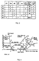
- FIG. 2 shows a chart that indicates the clutches and the brakes that are applied and released to establish each of the five forward-driving ratios as well as the reverse ratio.
- the sun gear 36 is anchored by a second and fourth ratio brake band 110. That brake band is applied also during fifth ratio operation so that sun gear 36 may act as a reaction point as the ring gear 34 is overdriven and as torque is delivered to the gear unit 28 through the carrier 38 and through the direct-drive clutch 108.
- the forward-drive clutch 106 is designated as clutch FWD
- the direct-drive clutch 108 is designated as clutch DIR
- the reverse disc brake 98 is referred to as the LO/REV brake
- the fifth ratio clutch 109 is identified as 5CL clutch
- brake band 110 is identified as 2/4 band.
- First ratio drive is achieved by engaging brake band 94, which anchors sun gear 44. Also, disc brake 98 is applied, and forward clutch 106 is applied. Thus, sun gear 78 is connected to the driven sprocket at 100, and the underdriven motion imparted to the carrier 80 is transferred to the ring gear 42 of gear unit 30.
- brake band 94 is referred to as the HB and REV band.
- the reverse clutch 102 is identified in FIG. 2 as the REV clutch.
- FIG. 3 A schematic representation of a microprocessor control system, shown generally at 200, is shown in FIG. 3.
- the engine is generally designated by reference numeral 228.
- Operating variables for the engine such as manifold pressure and coolant temperature and engine speed, are measured by analog sensors and distributed to an electronic microprocessor 230.
- the signal passage for manifold pressure is shown at 232.
- the engine coolant temperature signal is distributed to the processor 230 through signal line 234.
- the engine speed signal is distributed to the processor 230 through line 236.
- a signal indicating the range selection or transmission manual valve position is distributed through signal passage 238.
- Turbine speed also is measured, and that value is distributed to the processor through signal line 240.
- the torque output shaft speed for the transmission is distributed to the processor through signal line 242.
- a bypass clutch pressure signal is distributed to the processor through signal line 244, but that signal is irrelevant to the present invention.
- Transmission oil temperature for the engine is measured, and the signal representing that value is distributed to the processor through signal line 246.
- a brake signal is distributed to the processor through signal line 248. The presence of a signal at line 248 will indicate whether the vehicle brakes are applied or released by the vehicle operator.
- the processor 230 will receive the information developed by the sensors and condition it so that it may be used in digital form by the central processor unit.
- the central processor unit identified at 250 processes the information delivered to the processor 230 in a manner that will be described subsequently using algorithms that are stored in memory 252.
- the output signals from the processor 230 are delivered to a valve body 254 through signal line 256.
- the output data includes shift signals delivered to the shift solenoids that control the ratio changes. The operation of the valve body 254 and the solenoid signals are described in U.S. Pat. No 5,272,630.
- the output signal developed by the valve body 254 delivered through signal line 258 controls the operation of the clutches and brakes of the transmission illustrated in FIG. 1.
- FIG. 4 shows a prior art neutral idle clutch characteristics for a transmission having an open loop-type converter.
- the forward clutch pressure, the engine speed, the turbine speed and the output shaft torque assume initially the values shown in region A of FIG. 4.
- the turbine speed will increase, as shown at E, until it reaches the normal turbine speed for engine idle, which may be 600 rpm as shown at F in FIG. 4.
- the engine speed at that time in a typical vehicle installation may be about 800 rpm as shown at G.
- Figure 4 illustrates at point H what happens, according to the prior art, when the operator terminates the neutral idle mode by advancing the accelerator pedal. An immediate increase in the forward clutch pressure then will occur until a transition pressure indicated at I is reached. It is during this interval that the clutch servo cylinder is filling and the clutch servo piston is stroking. Because the engine throttle is advanced, the engine speed will respond to the advancing throttle and will increase as shown by the ramp J in FIG. 4. The engine speed continues to increase until the clutch servo is fully stroked. At that time, the engine speed will have reached a peak value shown at K.
- the achievement of the peak value M is coincident generally with the peak engine speed, the latter immediately decreasing in value at a fast rate, as shown at N.
- the decreasing engine speed is accompanied by a substantial inertia torque that contributes to the achievement of the peak value M for the output shaft torque.
- the clutch pressure will continue to increase following the stroking of the clutch servo piston and progressively increase at a rapid rate, as shown by the curve 0, until a final clutch pressure value is reached, as shown at P.
- the output shaft torque will be subjected to torque fluctuations, as demonstrated by the oscillating torque values Q following clutch engagement.
- microprocessor 230 for controlling engine idle speed during launch from neutral idle operation will now be described.
- the vehicle begins in the neutral idle operating condition (step 500).
- the neutral idle operating condition results in an exhaust of pressure from the forward clutch at time B in FIG. 4. This results in a decay of the forward clutch pressure over a short period of time, as indicated by the curve C in FIG. 4.
- the output shaft torque decays, as shown by curve D, as the forward clutch pressure is relieved.
- the turbine speed will increase, as shown at E, until it reaches the normal turbine speed for engine idle, which may be 600 rpm as shown at F in FIG. 4.
- the engine speed at that time in a typical vehicle installation may be about 800 rpm as shown at G.
- the vehicle operator releases the service brakes ⁇ step 502).
- the present invention can be used in connection with a variety of types of launches from neutral idle, the present invention is particularly useful in situations where the vehicle operator does not immediately depress the accelerator pedal to terminate neutral idle operation, as shown at H in FIG. 4. Rather, the vehicle operator merely allows the vehicle to creep forward, which results in a relatively slow engagement of the transmission.
- the engine idle speed during launch can be controlled by predicting a feedforward engine torque and then controlling the engine speed based upon that prediction.
- the feedforward engine torque is that predicted engine torque that is expected to be necessary to accommodate the increased torque required by the re-engaging transmission at a point in time in the near future.
- load is a generic term that represents the amount of torque that the transmission exerts on the engine at a given time.
- Fn_Conv_Load is a function of engine speed, turbine speed and other transmission variables, such as transmission fluid temperature, temperature of the friction plates, slip across the clutch, clutch design, and the like.
- Fn_Conv_Load is can be readily determined by one skilled in the art from relationships known to the skilled practitioner, namely the torque ratio function, Fn_Conv and a relationship that relates engine speed to the impeller torque.
- K Engine Speed Im pellerTorque
- Impeller Torque (Engine Speed/ (K (Turbine Speed/ Engine Speed)) 2
- impeller torque can be determined based on engine speed and turbine speed. It will be appreciated that the determination of Fn_Conv Load may be further refined by one of skill in the art by taking into account other transmission variable, such as transmission fluid temperature, temperature of the friction plates, slip across the clutch, clutch design, and the like.
- Nt_Pred max(Nt + Nt_Rate_Of_Change * Time_Into_Future,0)
- Fn_Cap is a function of clutch pressure and other transmission variables, such as transmission fluid temperature, temperature of the friction plates, slip across the clutch, clutch design, and the like.
- the feedforward or predicted torque converter load is limited to the lesser of the maximum torque converter load and the predicted torque converter load (step 512).
- the actual engine torque for controlling engine idle speed is determined by adding any other engine torque loads to the feedforward or predicted torque converter load (step 514).
- engine torque loads include, but are not limited to, engine accessories, such as air conditioning, pumps, and the like.
- the vehicle microprocessor determines whether the vehicle's launch from neutral idle is complete. If so, the algorithm ends (step 516). If not, then steps 502-514 are repeated.
- the vehicle begins in the neutral idle operating condition (step 600).
- the vehicle operator releases the service brakes (step 602) and allows the vehicle to creep forward, thereby causing the transmission to re-engage relatively slowly.
- Nt_Pred a feedforward turbine speed, Nt_Pred, is predicted at a time in the future based on a current turbine speed and a rate of change of the turbine speed (step 604).
- Nt_Pred max(Nt + Nt Rate_Of_Change * Time_Into_Future, 0)
- the second preferred method calculates the feedforward or predicted torque converter load in a continuous loop using the following expression (step 606):
- the Fn_Conv_Load function converts engine speed and turbine speed to engine brake torque independent of whether the forward clutch is engaged and is a function of engine speed, turbine speed and other transmission variables, such as transmission fluid temperature, clutch design, and the like.
- the actual engine torque required to control engine idle speed is determined by adding any other engine torque loads to the feedforward or predicted torque converter load (step 608).
- the microprocessor 230 determines whether the launch from neutral idle is complete. If so, the algorithm ends (step 610). If not, then steps 602-608 are repeated.
- the torque capacity of the forward clutch is not predicted and converted to an impeller torque as in steps 508 and 510 of the first method of the invention. Rather, the feedforward or predicted torque converter load is determined in a continuous loop.
- the present invention maintains a constant engine idle speed during launch and provides a smooth transition between transmission operating modes. This is accomplished by predicting the feedforward torque converter load to control engine torque throughout the launch period, unlike conventional methods. Then, the engine speed can be controlled by adjusting certain engine operating parameters, such as fuel injection amounts, air intake amounts, and other parameters known to those of skill in the art.
Landscapes
- Engineering & Computer Science (AREA)
- Mechanical Engineering (AREA)
- Chemical & Material Sciences (AREA)
- Combustion & Propulsion (AREA)
- General Engineering & Computer Science (AREA)
- Automation & Control Theory (AREA)
- Transportation (AREA)
- Control Of Transmission Device (AREA)
- Electrical Control Of Air Or Fuel Supplied To Internal-Combustion Engine (AREA)
Abstract
Description
- This invention relates in general to a method of controlling engine idle speed in an automotive vehicle and in particular to a method of controlling engine idle speed when a forward clutch of a transmission is engaged upon releasing the service brakes during launch from neutral idle operation.
- Neutral idle operation of a vehicle can be initiated when a vehicle is brought to a stand still position with the engine still running, as when a vehicle is stopped at a traffic light. In such situations, the transmission can be disengaged, i.e., neutral idle operation, which is beneficial to decrease overall vehicle fuel consumption by unloading the engine.
- More technically speaking, neutral idle operation of a vehicle is generally characterised by the vehicle being at rest, the service brakes being applied, the gear select lever being in a forward range, and all combinations of torque transmitting clutches that establish a speed ratio from the input to the output member of the transmission being disengaged.
- As a result, during neutral idle operation, the transmission input shaft rotates freely at a substantially synchronous speed with the engine output shaft.
- When a vehicle begins to move after being held stationary, it is said that the vehicle is launching from neutral idle operation. One method of launching from neutral idle operation is for the vehicle operator to merely cease applying the service brakes and allow the vehicle to creep forward. The inventors herein have recognized that this type of slow launch from neutral idle operation sometimes causes the vehicle to exhibit undesirable noise, vibration, and harshness (NVH) during the launch. The undesirable NVH is primarily a result of the engine speed changing during the launch from neutral idle to accommodate and react to the increased engine load of the transmission upon re-engagement. Specifically, as the transmission's clutch pressure increases or decreases, the torque load on the vehicle's torque converter turbine, and therefore also on the impeller, also increases or decreases. As a result, the transmission's forward clutch begins to slowly engage to transfer the engine torque through the transmission, and the vehicle begins to slowly creep ahead. However, because conventional methods of engine speed control regulate the engine speed based on an assumption that the transmission is either in a "Drive" or "Neutral" mode of operation (as opposed to a partial mode in between "Drive" and "Neutral"), the engine speed control system tends to respond unevenly throughout the launch period. This is because the engine speed control system is reacting to the slowly increasing load on the engine.
- Until recently, the NVH that results from the changing engine speed when the transmission engages has been relatively acceptable, primarily because vehicle operators have come to expect a certain amount of NVH when they physically move the vehicle's gear shifter from "Neutral" (or "Park") to a "Drive" position. However, because neutral idle operation is typically initiated by the vehicle itself, without the vehicle operator physically moving the gear shifter, the NVH that results from conventional engine speed control methods is more noticeable and undesirable.
- According to a first aspect of the invention there is provided a method of controlling a vehicle having an engine coupled to a transmission through a clutch, comprising the steps of determining a predicted torque converter load based on a clutch torque capacity during launch from neutral idle operation and adjusting an engine operating parameter to limit output engine torque to said predicted torque converter load.
- The method may further comprise the step of choosing a lesser of the predicted torque converter load and a maximum engine brake torque load.
- The clutch may be a forward clutch or alternatively the clutch may be a reverse clutch.
- The engine operating parameter may be a fuel injection amount.
- Alternatively, the engine operating parameter may be an air intake amount.
- According to a second aspect of the invention there is provided a method of controlling engine idle speed in a vehicle comprising the steps of determining a predicted torque converter load during launch from neutral idle operation and controlling engine torque output based on said predicted torque converter load.
- The predicted engine brake torque load may be based on estimations of a clutch torque capacity.
- The clutch may be a forward clutch.
- Alternatively, the clutch may be a reverse clutch.
- The engine torque output at a given time may be limited to the lesser of said predicted torque converter load and a maximum torque converter load.
- According to a third aspect of the invention there is provided a method of controlling engine idle speed during launch from neutral idle operation comprising the steps of determining a maximum engine brake torque load; determining a predicted engine brake torque load and adjusting an engine operating parameter to limit output engine torque to the lesser of said maximum engine brake torque load and said predicted torque converter load.
- The predicted torque converter load may be based on estimations of a clutch torque capacity.
- The clutch may be a forward clutch.
- The clutch may be a reverse clutch.
- According to a fourth aspect of the invention there is provided system for transferring power from a vehicle engine during launch from neutral idle operation, comprising a transmission including a torque input shaft, a torque output shaft, and a gear mechanism adapted to establish a torque flow path between the torque input shaft and the torque output shaft; a forward clutch for connecting the torque input shaft to the gear mechanism; and a microprocessor for determining a predicted torque converter load and controlling engine output torque based on said predicted torque converter load.
- The predicted torque converter load may be based on a clutch torque capacity.
- The clutch may be a forward clutch.
- Alternatively, the clutch may be a reverse clutch.
- The engine output torque may be limited by selecting the lesser of said predicted torque converter load and a maximum engine brake torque load.
- According to a fifth aspect of the invention there is provided a system for controlling a vehicle having an engine coupled to a transmission through a clutch, characterised in that the system includes electronic means programmed to determine a predicted torque converter load based on a clutch torque capacity during launch from neutral idle operation and to adjust at least one engine operating parameter to control output engine torque based on at least said predicted torque converter load.
- The clutch may be a forward clutch or may be a reverse clutch.
- The at least one engine operating parameter may be controlled to limit output engine torque to said predicted torque converter load
- The transmission may include a torque input means, a torque output means and a gear mechanism adapted to establish a torque flow path between the torque input means and the torque output means, a forward clutch for connecting the torque input means to the gear mechanism and a the electronic means is a microprocessor used to determine the predicted torque converter load and to control engine output torque based on at least said predicted torque converter load.
- The predicted torque converter load may be based on a clutch torque capacity.
- The engine output torque may be limited by selecting the lesser of said predicted torque converter load and a maximum torque converter load.
- The engine operating parameter may be an amount of injected fuel or may be an intake air amount.
- The invention will now be described by way of example with reference to the accompanying drawing of which:-
- FIG. 1 is a schematic representation of a planetary gear transmission having a forward clutch located in the torque flow path between a hydrokinetic torque converter turbine and the input elements of the gearing;
- FIG. 2 is a chart that shows a clutch and brake engagement and release pattern for the transmission shown in FIG. 1;
- FIG. 3 is a schematic representation of the control system including the electronic microprocessor for controlling clutch engagement in a closed-loop fashion;
- FIG. 4 is a graph that shows output torque and clutch pressure changes as well as the engine speed and turbine speed changes during a neutral idle condition and during a subsequent engagement of the forward clutch for a typical transmission of a prior art type;
- FIG. 5 is flow diagram of controlling engine idle speed during neutral idle operation according to a first method of the invention; and
- FIG. 6 is flow diagram of controlling engine idle speed during neutral idle operation according to a second method of the invention.
-
- Referring now to the drawings, there is illustrated in Fig. 1, a hydrokinetic torque converter, shown generally at 10, which includes a
bladed impeller 12 driveably connected to avehicle engine crankshaft 14. - A
bladed turbine 16 is connected to drivesprocket 18 of a chain transfer drive. Abladed stator 20 is located between the toroidal flow exit section of the turbine of the turbine flow entrance section of the impeller and acts in known fashion to change the direction of the toroidal fluid flow, thus making possible a torque multiplication in thetorque converter 10. - During steady-state operation in higher gear ratios, a
friction bypass clutch 22 may be engaged to driveably connect theimpeller 12 and theturbine 16, thus effectively removing the hydrokinetic torque flow path from the driveline.Stator 20 is anchored against rotation in a direction opposite to the direction of rotation of the impeller by anoverrunning brake 24, which is grounded tostator sleeve shaft 26. - A pair of simple
planetary gear units output shaft 32 that is arranged in spaced parallel disposition with respect to the engine crankshaft axis.Unit 28 includesring gear 34, sun gear 36,carrier 38 andplanet pinions 40 that are journalled oncarrier 38 in meshing engagement withring gear 34 and sun gear 36. - The
gear unit 30 comprisesring gear 42,sun gear 44,carrier 46 andplanet pinions 48, which are journalled oncarrier 46 in meshing engagement withsun gear 44 andring gear 42. -
Carrier 46 forms a torque output element for the gearing and is driveably connected tooutput member 48, which is connected to finaldrive sun gear 50 of final driveplanetary gear unit 52. - Final
drive gear unit 52 includes, in addition tosun gear 50, aring gear 54, acarrier 56 andplanet pinions 58 journalled oncarrier 56 in meshing engagement withsun gear 50 andring gear 54. Carrier 56 acts as a torque output element of thegear unit 52 and is connected toring gear 60 anddifferential gear unit 62. - A
compound carrier 64 forms a part of thegear unit 62 that rotatably journals a first pair ofpinions 66, which mesh with aring gear 60 and with a second set ofplanetary pinions 68, the latter meshing withsun gear 70. Sungear 70 in turn is driveably connected tooutput shaft 32. - Carrier 64 is driveably connected to a companion
torque output shaft 72.Shaft 32 is connected to one traction wheel of the vehicle, and the opposite traction wheel of the vehicle is connected tooutput shaft 72. The connections between the traction wheels and the respective output shafts are achieved by universal coupling and half shaft assemblies in a known fashion. - A third simple
planetary gear unit 74 is located between the pair of gear units previously described and the hydrokinetic torque converter. It comprises aring gear 76, asun gear 78, acarrier 80 andplanet pinions 82 journalled on thecarrier 80 in meshing engagement withring gear 76 andsun gear 78. - The
carrier 80 is connected to torquetransfer sleeve shaft 84, which is driveably connected to ringgear 34 ofgear unit 28 and to ringgear 42 ofgear unit 30. An overrunningbrake 86 that has anouter race 88 grounded to the transmission housing as shown at 90 is adapted to anchorsun gear 44 during operation in each of the first four overdriving ratios, thus providing a torque reaction point for the gear system. - The
ring gear 54 is permanently anchored to the housing as shown at 92, thus permitting the finaldrive gear unit 52 to multiply the torque delivered through thegear units - A
friction brake band 94 surroundsbrake drum 96 which itself is connected tosun gear 44. Thebrake band 94 is applied to anchor thesun gear 44 during hill braking operation and during reverse-drive operation. - A disc brake shown generally at 98 is adapted to anchor the
carrier 38 against the transmission housing during operation in the lowest ratio and in reverse drive. Sun gear 36 is a torque input element flow transmission. During operation in reverse drive, sun gear 36 is connected to drivensprocket 100 by means of reverse clutch 102, the latter acting as a driving connection between the drivensprocket 100 andbrake drum 104. Sun gear 36 is connected directly to thebrake drum 104.Driven sprocket 100 is connected to drivingsprocket 18 through a torquetransfer drive chain 106. - During forward drive operation, drive
sprocket 100 is connected to sun gear 75 byforward drive clutch 106. Theforward drive clutch 106 is engaged during operation in the first three forward-driving ratios. - A direct-
drive clutch 108 connectsring gear 76 with the drivensprocket 100 during operation in the third and fourth forward driving ratios as well as during the fifth driving ratio. - When
direct drive clutch 108 and theforward clutch 106 are engaged simultaneously,ring gear 76 is connected tosun gear 78 so that the elements of thegear unit 74 rotate in unison with a one-to-one speed ratio. - To effect a fifth forward-driving ratio, friction clutch 109 is applied, thus establishing a driving connection between
sleeve shaft 84 andsun gear 44 ofgear unit 30 to locksun gear 44 to ringgear 42 so that the speed ratio developed bygear unit 30 is unity. - The neutral idle feature of the invention is achieved by controlling engagement and release of
forward clutch 106. When the vehicle is at a standstill and the engine is idling, theengine 10 will tend to drive the turbine because of the hydrokinetic torque multiplication effect of theconverter 10. Thus, a driving torque will be delivered to the traction wheels through the gearing, even when the engine is idling. - In prior art designs, it is necessary to maintain the accelerator pedal at a sufficiently advanced position so that the engine will idle at a speed that will avoid undue engine harshness. It further is necessary for the vehicle operator to maintain his foot on the vehicle brake to avoid creeping of the vehicle with the engine idling. By disengaging the clutch 106 to establish a neutral idle condition, the torque flow path to the traction wheel is interrupted when the engine is idling with the vehicle at a standstill.
- FIG. 2 shows a chart that indicates the clutches and the brakes that are applied and released to establish each of the five forward-driving ratios as well as the reverse ratio. The sun gear 36 is anchored by a second and fourth
ratio brake band 110. That brake band is applied also during fifth ratio operation so that sun gear 36 may act as a reaction point as thering gear 34 is overdriven and as torque is delivered to thegear unit 28 through thecarrier 38 and through the direct-drive clutch 108. In FIG. 2, the forward-drive clutch 106 is designated as clutch FWD, the direct-drive clutch 108 is designated as clutch DIR, thereverse disc brake 98 is referred to as the LO/REV brake, the fifth ratio clutch 109 is identified as 5CL clutch, andbrake band 110 is identified as 2/4 band. - First ratio drive is achieved by engaging
brake band 94, which anchorssun gear 44. Also,disc brake 98 is applied, and forward clutch 106 is applied. Thus,sun gear 78 is connected to the driven sprocket at 100, and the underdriven motion imparted to thecarrier 80 is transferred to thering gear 42 ofgear unit 30. In FIG. 2,brake band 94 is referred to as the HB and REV band. Thereverse clutch 102 is identified in FIG. 2 as the REV clutch. - A schematic representation of a microprocessor control system, shown generally at 200, is shown in FIG. 3. The engine is generally designated by
reference numeral 228. - Operating variables for the engine, such as manifold pressure and coolant temperature and engine speed, are measured by analog sensors and distributed to an electronic microprocessor 230. The signal passage for manifold pressure is shown at 232. The engine coolant temperature signal is distributed to the processor 230 through
signal line 234. The engine speed signal is distributed to the processor 230 throughline 236. - Other variables that are measured and distributed to the processor are a signal indicating the range selection or transmission manual valve position. This signal is distributed through
signal passage 238. Turbine speed also is measured, and that value is distributed to the processor throughsignal line 240. The torque output shaft speed for the transmission is distributed to the processor throughsignal line 242. A bypass clutch pressure signal is distributed to the processor throughsignal line 244, but that signal is irrelevant to the present invention. - Transmission oil temperature for the engine is measured, and the signal representing that value is distributed to the processor through
signal line 246. A brake signal is distributed to the processor throughsignal line 248. The presence of a signal atline 248 will indicate whether the vehicle brakes are applied or released by the vehicle operator. - The processor 230 will receive the information developed by the sensors and condition it so that it may be used in digital form by the central processor unit.
- The central processor unit identified at 250 processes the information delivered to the processor 230 in a manner that will be described subsequently using algorithms that are stored in
memory 252. The output signals from the processor 230 are delivered to avalve body 254 throughsignal line 256. The output data includes shift signals delivered to the shift solenoids that control the ratio changes. The operation of thevalve body 254 and the solenoid signals are described in U.S. Pat. No 5,272,630. - The output signal developed by the
valve body 254 delivered throughsignal line 258 controls the operation of the clutches and brakes of the transmission illustrated in FIG. 1. - For purposes of describing the benefits of the present invention, a comparison to prior art neutral idle characteristics will first be made with reference to FIG. 4, which shows a prior art neutral idle clutch characteristics for a transmission having an open loop-type converter.
- This type of transmission is further described in U.S. Pat. No. 5,272,630. In FIG. 4, time is plotted on the abscissa; and output shaft torque, clutch fluid pressure, engine speed and turbine speed are plotted on the ordinate.
- The forward clutch pressure, the engine speed, the turbine speed and the output shaft torque assume initially the values shown in region A of FIG. 4.
- It is seen from FIG. 4 that the turbine speed is zero since the vehicle is at rest. The difference between engine speed and turbine speed represents the slip that exists when the vehicle comes to rest and before the neutral idle mode begins. At time B, the neutral idle mode is initiated, which results in an exhaust of pressure from the forward clutch. This results in a decay of the forward clutch pressure over a short period of time, as indicated by the curve C in FIG. 4. The output shaft torque decays, as shown by curve D, as the forward clutch pressure is relieved.
- As the forward clutch looses capacity following initiation of a neutral start mode, the turbine speed will increase, as shown at E, until it reaches the normal turbine speed for engine idle, which may be 600 rpm as shown at F in FIG. 4. The engine speed at that time in a typical vehicle installation may be about 800 rpm as shown at G.
- Figure 4 illustrates at point H what happens, according to the prior art, when the operator terminates the neutral idle mode by advancing the accelerator pedal. An immediate increase in the forward clutch pressure then will occur until a transition pressure indicated at I is reached. It is during this interval that the clutch servo cylinder is filling and the clutch servo piston is stroking. Because the engine throttle is advanced, the engine speed will respond to the advancing throttle and will increase as shown by the ramp J in FIG. 4. The engine speed continues to increase until the clutch servo is fully stroked. At that time, the engine speed will have reached a peak value shown at K.
- When the piston for the forward clutch servo is stroked and the forward clutch gains capacity, the output shaft torque will sharply rise, as indicated by the steep slope curved portion L, until it reaches a peak value shown at M.
- The achievement of the peak value M is coincident generally with the peak engine speed, the latter immediately decreasing in value at a fast rate, as shown at N. The decreasing engine speed is accompanied by a substantial inertia torque that contributes to the achievement of the peak value M for the output shaft torque. The clutch pressure will continue to increase following the stroking of the clutch servo piston and progressively increase at a rapid rate, as shown by the
curve 0, until a final clutch pressure value is reached, as shown at P. The output shaft torque will be subjected to torque fluctuations, as demonstrated by the oscillating torque values Q following clutch engagement. - The control strategy of the present invention that avoids these undesirable features of the prior art will now be explained with reference to FIG. 5.
- Referring now to FIG. 5, the first preferred routine executed by microprocessor 230 for controlling engine idle speed during launch from neutral idle operation will now be described.
- The vehicle begins in the neutral idle operating condition (step 500). As described above, the neutral idle operating condition results in an exhaust of pressure from the forward clutch at time B in FIG. 4. This results in a decay of the forward clutch pressure over a short period of time, as indicated by the curve C in FIG. 4. The output shaft torque decays, as shown by curve D, as the forward clutch pressure is relieved. As the forward clutch loses capacity following initiation of a neutral start mode, the turbine speed will increase, as shown at E, until it reaches the normal turbine speed for engine idle, which may be 600 rpm as shown at F in FIG. 4. The engine speed at that time in a typical vehicle installation may be about 800 rpm as shown at G.
- At some point after being maintained in neutral idle operation for a period of time, the vehicle operator releases the service brakes {step 502). Though the present invention can be used in connection with a variety of types of launches from neutral idle, the present invention is particularly useful in situations where the vehicle operator does not immediately depress the accelerator pedal to terminate neutral idle operation, as shown at H in FIG. 4. Rather, the vehicle operator merely allows the vehicle to creep forward, which results in a relatively slow engagement of the transmission.
- According to the present invention, the engine idle speed during launch can be controlled by predicting a feedforward engine torque and then controlling the engine speed based upon that prediction. The feedforward engine torque is that predicted engine torque that is expected to be necessary to accommodate the increased torque required by the re-engaging transmission at a point in time in the near future.
- As used herein, the term "load" is a generic term that represents the amount of torque that the transmission exerts on the engine at a given time.
- According to a first embodiment of the invention, the predicted required engine torque is limited to the minimum of an estimated torque converter load when the forward clutch is fully engaged (i.e: turbine speed equal to zero) and the predicted torque required by the re-engaging transmission. This is done to allow the forward clutch to engage at a desired rate while preventing excessive clutch slippage and engine flare. Therefore, the maximum torque converter load is calculated (step 504) according to the following expression:
Max_Converter_Tq_Load = Fn_Conv_Load (Ne, Nt and other transmission variables),
where:- - Ne is the engine speed,
- Nt is the turbine speed and is assumed equal to zero,
and - Fn_Conv_Load converts engine speed and turbine speed to engine brake torque independent of whether the forward clutch is engaged.
-
- Fn_Conv_Load is a function of engine speed, turbine speed and other transmission variables, such as transmission fluid temperature, temperature of the friction plates, slip across the clutch, clutch design, and the like.
- Fn_Conv_Load is can be readily determined by one skilled in the art from relationships known to the skilled practitioner, namely the torque ratio function, Fn_Conv and a relationship that relates engine speed to the impeller torque.
- The relationship between engine speed and impeller torque, otherwise known as the K-factor, can be expressed as:
- The numerical values for the K-factor can be determined empirically by one skilled in the art. The above equation can be rearranged as follows:
- The above equation exemplifies that the impeller torque can be determined based on engine speed and turbine speed. It will be appreciated that the determination of Fn_Conv Load may be further refined by one of skill in the art by taking into account other transmission variable, such as transmission fluid temperature, temperature of the friction plates, slip across the clutch, clutch design, and the like.
- Then, a predicted future turbine speed, Nt-Pred, is calculated based on the current turbine speed and a rate of change of the turbine speed (step 506), according to the following expression:
- Next, as shown in
step 508, the torque capacity of the forward clutch at any given time throughout the launch period is calculated using the following equation:
Fn_Cap converts either a commanded or measured forward clutch pressure into a torque capacity. Fn_Cap is a function of clutch pressure and other transmission variables, such as transmission fluid temperature, temperature of the friction plates, slip across the clutch, clutch design, and the like. Fn-Cap includes a conversion factor from torque measured at the forward clutch to torque measured at the turbine shaft and can be expressed as
m and b are constants that are determined empirically by one skilled in the art. - Then, a feedforward or predicted torque converter load is determined (step 510) by the following expression:
Fn_Conv is the torque multiplication or ratio of the torque converter and can be determined by one skilled in the art by plotting the torque ratio (turbine torque / engine torque) as a function of the speed ratio (turbine speed / engine speed). The numerical values for turbine speed and torque, and engine speed and torque can be determined empirically by one skilled in the art. - Next, the feedforward or predicted torque converter load is limited to the lesser of the maximum torque converter load and the predicted torque converter load (step 512). In terms of a mathematical expression, the predicted torque converter load is expressed as follows:
- Then, the actual engine torque for controlling engine idle speed is determined by adding any other engine torque loads to the feedforward or predicted torque converter load (step 514). Examples of other engine torque loads include, but are not limited to, engine accessories, such as air conditioning, pumps, and the like.
- Finally, the vehicle microprocessor determines whether the vehicle's launch from neutral idle is complete. If so, the algorithm ends (step 516). If not, then steps 502-514 are repeated.
- Referring now to FIG. 6, a second embodiment of a method in accordance with the invention will now be described. As in the first method, the vehicle begins in the neutral idle operating condition (step 600). At some point, the vehicle operator releases the service brakes (step 602) and allows the vehicle to creep forward, thereby causing the transmission to re-engage relatively slowly.
- Then, as in the first preferred embodiment, a feedforward turbine speed, Nt_Pred, is predicted at a time in the future based on a current turbine speed and a rate of change of the turbine speed (step 604). The same expression as in the first preferred embodiment is used here:
- Unlike the first preferred embodiment though, the second preferred method calculates the feedforward or predicted torque converter load in a continuous loop using the following expression (step 606):
Ne is the engine speed,
Fn_Conv_Load is identical to the mathematical function having the same name described in connection with the first preferred embodiment. - The Fn_Conv_Load function converts engine speed and turbine speed to engine brake torque independent of whether the forward clutch is engaged and is a function of engine speed, turbine speed and other transmission variables, such as transmission fluid temperature, clutch design, and the like.
- After the feedforward or predicted torque converter load is calculated, the actual engine torque required to control engine idle speed is determined by adding any other engine torque loads to the feedforward or predicted torque converter load (step 608).
- Examples of other engine torque loads include, but are not limited to, engine accessories, such as air conditioning, pumps, and the like. Then, the microprocessor 230 determines whether the launch from neutral idle is complete. If so, the algorithm ends (step 610). If not, then steps 602-608 are repeated.
- Unlike the first preferred embodiment of the invention, in the second method of the invention, the torque capacity of the forward clutch is not predicted and converted to an impeller torque as in
steps - Irrespective of which of the preferred methods is used, the present invention maintains a constant engine idle speed during launch and provides a smooth transition between transmission operating modes. This is accomplished by predicting the feedforward torque converter load to control engine torque throughout the launch period, unlike conventional methods. Then, the engine speed can be controlled by adjusting certain engine operating parameters, such as fuel injection amounts, air intake amounts, and other parameters known to those of skill in the art.
- Although preferred embodiments of the present invention have been disclosed, a person of ordinary skill in the art will realise that certain modifications can be made without departing from the scope of this invention.
- For example, the teachings of this invention apply when a different clutch other than the forward clutch or identified as the forward clutch is allowed to slip during neutral idle operation. Therefore, the following claims should be studied to determine the true scope and content of the invention.
Claims (10)
- A method of controlling a vehicle having an engine coupled to a transmission through a clutch characterised in that the method comprises the steps of determining a predicted torque converter load based on a clutch torque capacity during launch from neutral idle operation and adjusting an engine operating parameter to limit output engine torque to said predicted torque converter load.
- A method as claimed Claim 1, further comprising the step of choosing a lesser of the predicted torque converter load and a maximum engine brake torque load.
- A method of controlling engine idle speed in a vehicle characterised in that the method comprises the steps of determining a predicted torque converter load during launch from neutral idle operation and controlling engine torque output based on said predicted torque converter load.
- A method as claimed Claim 3 wherein the predicted engine brake torque load is based on estimations of a clutch torque capacity.
- A method as claimed Claim 7, wherein the engine torque output at a given time is limited to the lesser of said predicted torque converter load and a maximum torque converter load.
- A method of controlling engine idle speed during launch from neutral idle operation characterised in that the method comprises the steps of determining a maximum engine brake torque load; determining a predicted engine brake torque load and adjusting an engine operating parameter to limit output engine torque to the lesser of said maximum engine brake torque load and said predicted torque converter load.
- A method as claimed Claim 12, wherein the predicted torque converter load is based on estimations of a clutch torque capacity.
- A system for transferring power from a vehicle engine during launch from neutral idle operation characterised in that the system comprises a transmission including a torque input shaft, a torque output shaft, and a gear mechanism adapted to establish a torque flow path between the torque input shaft and the torque output shaft; a forward clutch for connecting the torque input shaft to the gear mechanism; and a microprocessor for determining a predicted torque converter load and controlling engine output torque based on said predicted torque converter load.
- The system of Claim 16, wherein said predicted torque converter load is based on a clutch torque capacity.
- A method as claimed Claim 16, wherein said engine output torque is limited by selecting the lesser of said predicted torque converter load and a maximum engine brake torque load.
Applications Claiming Priority (2)
| Application Number | Priority Date | Filing Date | Title |
|---|---|---|---|
| US09/779,815 US6634984B1 (en) | 2001-02-08 | 2001-02-08 | Method of controlling engine idle speed during launch from neutral idle operation |
| US779815 | 2001-02-08 |
Publications (3)
| Publication Number | Publication Date |
|---|---|
| EP1231397A2 true EP1231397A2 (en) | 2002-08-14 |
| EP1231397A3 EP1231397A3 (en) | 2005-07-20 |
| EP1231397B1 EP1231397B1 (en) | 2007-12-26 |
Family
ID=25117661
Family Applications (1)
| Application Number | Title | Priority Date | Filing Date |
|---|---|---|---|
| EP02100028A Expired - Lifetime EP1231397B1 (en) | 2001-02-08 | 2002-01-17 | Engine idle speed control using predicted torque converter load |
Country Status (3)
| Country | Link |
|---|---|
| US (1) | US6634984B1 (en) |
| EP (1) | EP1231397B1 (en) |
| DE (1) | DE60224236T2 (en) |
Cited By (4)
| Publication number | Priority date | Publication date | Assignee | Title |
|---|---|---|---|---|
| WO2005021951A1 (en) * | 2003-08-22 | 2005-03-10 | Daimlerchrysler Ag | Method for operating an internal combustion engine comprising an exhaust gas purification system |
| EP1571314A1 (en) * | 2004-03-01 | 2005-09-07 | Nissan Motor Company, Limited | Engine idle speed control device |
| CN102030000A (en) * | 2009-09-28 | 2011-04-27 | 通用汽车环球科技运作公司 | Method and apparatus for neutral idle clutch control |
| US8108108B2 (en) | 2003-03-27 | 2012-01-31 | Torotrak (Development) Limited | Method of controlling a continuously variable transmission |
Families Citing this family (22)
| Publication number | Priority date | Publication date | Assignee | Title |
|---|---|---|---|---|
| JP4134654B2 (en) * | 2002-09-25 | 2008-08-20 | 日産自動車株式会社 | Idle speed control device for internal combustion engine |
| JP2004211640A (en) * | 2003-01-07 | 2004-07-29 | Nissan Motor Co Ltd | Control device for engine |
| US7198588B2 (en) * | 2003-06-11 | 2007-04-03 | Ford Global Technologies, Llc. | System and method for controlling engine idle in a vehicle |
| JP4483879B2 (en) * | 2007-03-09 | 2010-06-16 | トヨタ自動車株式会社 | Control device for vehicle drive device |
| US7832518B2 (en) * | 2007-03-22 | 2010-11-16 | Ford Global Technologies, Llc | Torque distribution control in a motor vehicle |
| US8079933B2 (en) * | 2007-11-04 | 2011-12-20 | GM Global Technology Operations LLC | Method and apparatus to control engine torque to peak main pressure for a hybrid powertrain system |
| US7993242B2 (en) * | 2008-04-18 | 2011-08-09 | Caterpillar Inc. | Machine control system with directional shift management |
| US8639418B2 (en) * | 2008-04-18 | 2014-01-28 | Caterpillar Inc. | Machine control system with directional shift management |
| DE102008043107A1 (en) * | 2008-10-23 | 2010-04-29 | Zf Friedrichshafen Ag | Method for reversing the direction of travel of a vehicle |
| JP5229572B2 (en) * | 2009-03-25 | 2013-07-03 | アイシン・エィ・ダブリュ株式会社 | Vehicle control device and vehicle drive system |
| US8321101B2 (en) | 2009-05-05 | 2012-11-27 | Ford Global Technologies, Llc | Temperature dependent minimum transmission input speed |
| US8620544B2 (en) * | 2009-09-24 | 2013-12-31 | GM Global Technology Operations LLC | Method and apparatus for entering neutral idle from a forward drive mode |
| DE102009058139A1 (en) * | 2009-12-12 | 2011-06-16 | Volkswagen Ag | Method and device for controlling a vehicle to an object |
| JP5551762B2 (en) * | 2010-02-23 | 2014-07-16 | 本田技研工業株式会社 | Starting clutch control device |
| US8874331B2 (en) | 2011-05-16 | 2014-10-28 | Toyota Motor Engineering & Manufacturing North America, Inc. | Method and apparatus for idle speed control based on variable torque converter load |
| US10208455B2 (en) * | 2016-03-17 | 2019-02-19 | Deere & Company | In-vehicle dynometer |
| US10054073B2 (en) | 2016-06-01 | 2018-08-21 | Paccar Inc | Method to elevate idle speed to launch a vehicle with manual transmission |
| US10132255B2 (en) | 2017-01-04 | 2018-11-20 | GM Global Technology Operations LLC | System and method for vehicle engine speed control during a garage shift |
| US10112612B2 (en) | 2017-02-16 | 2018-10-30 | Ford Global Technologies, Llc | Coordinated actuation of vehicle stop modes |
| US10308252B2 (en) | 2017-09-12 | 2019-06-04 | Ford Global Technologies, Llc | Method of controlling a powertrain |
| US10377369B2 (en) * | 2017-12-12 | 2019-08-13 | Ford Global Technologies, Llc | Methods and system for predicting driveline disconnect clutch torque |
| GB2571330B (en) * | 2018-02-26 | 2021-07-28 | Jaguar Land Rover Ltd | Control of vehicle traction motor torque before stall launch |
Citations (1)
| Publication number | Priority date | Publication date | Assignee | Title |
|---|---|---|---|---|
| US5272630A (en) | 1992-09-15 | 1993-12-21 | Ford Motor Company | Automatic transmission control and strategy for neutral idle |
Family Cites Families (21)
| Publication number | Priority date | Publication date | Assignee | Title |
|---|---|---|---|---|
| US4476745A (en) | 1981-09-14 | 1984-10-16 | Ford Motor Company | Control system for an automatic transmission having a neutral coast and idle feature |
| JPS59501584A (en) | 1982-09-20 | 1984-09-06 | フオ−ド モ−タ− カンパニ− | power transmission mechanism |
| JPH0245625A (en) * | 1988-08-08 | 1990-02-15 | Nissan Motor Co Ltd | Engine idling revolution compensating device for vehicle equipped with automatic transmission |
| US5213186A (en) * | 1990-11-30 | 1993-05-25 | Toyota Jidosha Kabushiki Kaisha | Control system and method for automatic transmission |
| US5123302A (en) * | 1990-12-24 | 1992-06-23 | Ford Motor Company | Automatic transmission gearshift control having feedforward response of clutch and its hydraulic actuation |
| DE4304779B4 (en) * | 1992-06-20 | 2005-11-24 | Robert Bosch Gmbh | Device for controlling the torque to be delivered by a drive unit of a vehicle |
| JP3445291B2 (en) * | 1992-10-13 | 2003-09-08 | 株式会社日立製作所 | Drive torque control device |
| US5374224A (en) * | 1993-12-23 | 1994-12-20 | Ford Motor Company | System and method for controlling the transient torque output of a variable displacement internal combustion engine |
| DE19535442B4 (en) * | 1995-09-23 | 2006-04-20 | Robert Bosch Gmbh | Method and device for controlling the idling of a drive unit |
| JP3246863B2 (en) * | 1996-03-15 | 2002-01-15 | 株式会社日立製作所 | Control device for automatic transmission |
| US5795262A (en) | 1996-04-15 | 1998-08-18 | General Motors Corporation | Automatic neutral to drive shift control |
| JPH09324663A (en) * | 1996-06-03 | 1997-12-16 | Toyota Motor Corp | Integrated control device for engine and for automatic transmission |
| US5738605A (en) * | 1996-06-28 | 1998-04-14 | Chrysler Corporation | Anti-hunt strategy for an automatic transmission |
| JPH1037787A (en) * | 1996-07-24 | 1998-02-10 | Fuji Heavy Ind Ltd | Idling rotational speed control device for vehicle engine |
| US5738606A (en) * | 1996-09-30 | 1998-04-14 | Cummins Engine Company, Inc. | Control system for regulating output torque of an internal combustion engine |
| DE69806685T2 (en) * | 1997-05-22 | 2002-11-21 | Nissan Motor Co., Ltd. | Integrated control system for electronically controlled internal combustion engine and continuously variable automatic transmission |
| JPH11200909A (en) * | 1998-01-09 | 1999-07-27 | Denso Corp | Vehicular engine rotation speed controlling device |
| US6098004A (en) * | 1998-06-04 | 2000-08-01 | Ford Global Technologies, Inc. | Preventing gear hunting in an automatic transmission for a motor vehicle |
| US6266597B1 (en) * | 1999-10-12 | 2001-07-24 | Ford Global Technologies, Inc. | Vehicle and engine control system and method |
| US6278926B1 (en) * | 2000-09-18 | 2001-08-21 | Ford Global Technologies, Inc. | Adaptive electronic transmission control system and strategy for nonsynchronous automatic transmission |
| US6434467B1 (en) * | 2000-09-26 | 2002-08-13 | Ford Global Technologies, Inc. | Vehicle control method for vehicle having a torque converter |
-
2001
- 2001-02-08 US US09/779,815 patent/US6634984B1/en not_active Expired - Lifetime
-
2002
- 2002-01-17 EP EP02100028A patent/EP1231397B1/en not_active Expired - Lifetime
- 2002-01-17 DE DE60224236T patent/DE60224236T2/en not_active Expired - Lifetime
Patent Citations (1)
| Publication number | Priority date | Publication date | Assignee | Title |
|---|---|---|---|---|
| US5272630A (en) | 1992-09-15 | 1993-12-21 | Ford Motor Company | Automatic transmission control and strategy for neutral idle |
Cited By (7)
| Publication number | Priority date | Publication date | Assignee | Title |
|---|---|---|---|---|
| US8108108B2 (en) | 2003-03-27 | 2012-01-31 | Torotrak (Development) Limited | Method of controlling a continuously variable transmission |
| US8892315B2 (en) | 2003-03-27 | 2014-11-18 | Torotrak (Development) Limited | Method of controlling a continuously variable transmission |
| WO2005021951A1 (en) * | 2003-08-22 | 2005-03-10 | Daimlerchrysler Ag | Method for operating an internal combustion engine comprising an exhaust gas purification system |
| US7418334B2 (en) | 2003-08-22 | 2008-08-26 | Daimler Ag | Method for operating an internal combustion engine comprising an exhaust gas purification system |
| EP1571314A1 (en) * | 2004-03-01 | 2005-09-07 | Nissan Motor Company, Limited | Engine idle speed control device |
| US7169078B2 (en) | 2004-03-01 | 2007-01-30 | Nissan Motor Co., Ltd. | Engine idle speed control device |
| CN102030000A (en) * | 2009-09-28 | 2011-04-27 | 通用汽车环球科技运作公司 | Method and apparatus for neutral idle clutch control |
Also Published As
| Publication number | Publication date |
|---|---|
| US6634984B1 (en) | 2003-10-21 |
| DE60224236D1 (en) | 2008-02-07 |
| EP1231397B1 (en) | 2007-12-26 |
| EP1231397A3 (en) | 2005-07-20 |
| DE60224236T2 (en) | 2008-12-18 |
Similar Documents
| Publication | Publication Date | Title |
|---|---|---|
| EP1231397B1 (en) | Engine idle speed control using predicted torque converter load | |
| US6299565B1 (en) | Control strategy for an automatic transmission | |
| US5272630A (en) | Automatic transmission control and strategy for neutral idle | |
| US6440041B1 (en) | Method of controlling engine torque during launch from neutral idle operation | |
| US5603672A (en) | Method for controlling the output torque of an automatic transmission | |
| US8296028B2 (en) | Control device and control method for lockup clutch and engine torque in a vehicle | |
| US6449548B1 (en) | Automatic transmission shift control | |
| US6799109B2 (en) | Vehicle control apparatus | |
| CA2109890C (en) | Engine control method for use with automatic clutch control | |
| US9050963B2 (en) | Control apparatus for vehicular power transmitting apparatus | |
| US9707969B2 (en) | Vehicle control system | |
| US20070243971A1 (en) | Torque converter bypass clutch control | |
| EP1564055A2 (en) | Launch control of a hybrid vehicle | |
| US8287431B2 (en) | Vehicular control apparatus and vehicular control method | |
| US8046143B2 (en) | Automatic gear control device | |
| US20140200112A1 (en) | Control apparatus for vehicle | |
| US7194348B2 (en) | High acceleration time shift control apparatus and control method for vehicle | |
| US20040186645A1 (en) | Control apparatus and method for friction device of vehicle | |
| US7416510B2 (en) | Control of a vehicle powertrain with multiple prime movers | |
| JP2004052643A (en) | Vehicle neutral control device | |
| US6283891B1 (en) | Automatic transmission for an automotive vehicle with a shift control for launch assist and manual upshifts | |
| JP6170459B2 (en) | Control device and control method for forward / reverse switching device | |
| US10428938B2 (en) | Method and system for controlling a vehicle propulsion system | |
| JP4063002B2 (en) | Control device for power transmission mechanism for vehicle | |
| JP2652370B2 (en) | Automatic clutch control system for vehicles |
Legal Events
| Date | Code | Title | Description |
|---|---|---|---|
| PUAI | Public reference made under article 153(3) epc to a published international application that has entered the european phase |
Free format text: ORIGINAL CODE: 0009012 |
|
| AK | Designated contracting states |
Kind code of ref document: A2 Designated state(s): AT BE CH CY DE DK ES FI FR GB GR IE IT LI LU MC NL PT SE TR |
|
| AX | Request for extension of the european patent |
Free format text: AL;LT;LV;MK;RO;SI |
|
| PUAL | Search report despatched |
Free format text: ORIGINAL CODE: 0009013 |
|
| AK | Designated contracting states |
Kind code of ref document: A3 Designated state(s): AT BE CH CY DE DK ES FI FR GB GR IE IT LI LU MC NL PT SE TR |
|
| AX | Request for extension of the european patent |
Extension state: AL LT LV MK RO SI |
|
| RIC1 | Information provided on ipc code assigned before grant |
Ipc: 7B 60K 41/04 B Ipc: 7F 16H 63/50 B Ipc: 7F 16D 41/08 A Ipc: 7F 16H 61/21 B Ipc: 7B 60K 41/22 B Ipc: 7F 16H 61/14 B |
|
| 17P | Request for examination filed |
Effective date: 20051227 |
|
| AKX | Designation fees paid |
Designated state(s): DE FR GB |
|
| GRAP | Despatch of communication of intention to grant a patent |
Free format text: ORIGINAL CODE: EPIDOSNIGR1 |
|
| RIC1 | Information provided on ipc code assigned before grant |
Ipc: F16H 61/14 20060101ALI20070814BHEP Ipc: F02D 41/08 20060101AFI20070814BHEP |
|
| GRAS | Grant fee paid |
Free format text: ORIGINAL CODE: EPIDOSNIGR3 |
|
| GRAA | (expected) grant |
Free format text: ORIGINAL CODE: 0009210 |
|
| RAP1 | Party data changed (applicant data changed or rights of an application transferred) |
Owner name: FORD GLOBAL TECHNOLOGIES, LLC |
|
| AK | Designated contracting states |
Kind code of ref document: B1 Designated state(s): DE FR GB |
|
| REG | Reference to a national code |
Ref country code: GB Ref legal event code: FG4D |
|
| REF | Corresponds to: |
Ref document number: 60224236 Country of ref document: DE Date of ref document: 20080207 Kind code of ref document: P |
|
| ET | Fr: translation filed | ||
| PLBE | No opposition filed within time limit |
Free format text: ORIGINAL CODE: 0009261 |
|
| STAA | Information on the status of an ep patent application or granted ep patent |
Free format text: STATUS: NO OPPOSITION FILED WITHIN TIME LIMIT |
|
| 26N | No opposition filed |
Effective date: 20080929 |
|
| PGFP | Annual fee paid to national office [announced via postgrant information from national office to epo] |
Ref country code: FR Payment date: 20090106 Year of fee payment: 8 |
|
| REG | Reference to a national code |
Ref country code: FR Ref legal event code: ST Effective date: 20100930 |
|
| PG25 | Lapsed in a contracting state [announced via postgrant information from national office to epo] |
Ref country code: FR Free format text: LAPSE BECAUSE OF NON-PAYMENT OF DUE FEES Effective date: 20100201 |
|
| PGFP | Annual fee paid to national office [announced via postgrant information from national office to epo] |
Ref country code: GB Payment date: 20101215 Year of fee payment: 10 |
|
| GBPC | Gb: european patent ceased through non-payment of renewal fee |
Effective date: 20130117 |
|
| PG25 | Lapsed in a contracting state [announced via postgrant information from national office to epo] |
Ref country code: GB Free format text: LAPSE BECAUSE OF NON-PAYMENT OF DUE FEES Effective date: 20130117 |
|
| REG | Reference to a national code |
Ref country code: DE Ref legal event code: R082 Ref document number: 60224236 Country of ref document: DE Representative=s name: DOERFLER, THOMAS, DR.-ING., DE |
|
| PGFP | Annual fee paid to national office [announced via postgrant information from national office to epo] |
Ref country code: DE Payment date: 20180109 Year of fee payment: 17 |
|
| REG | Reference to a national code |
Ref country code: DE Ref legal event code: R119 Ref document number: 60224236 Country of ref document: DE |
|
| PG25 | Lapsed in a contracting state [announced via postgrant information from national office to epo] |
Ref country code: DE Free format text: LAPSE BECAUSE OF NON-PAYMENT OF DUE FEES Effective date: 20190801 |