EP1231026A2 - Rotation locking mechanism - Google Patents
Rotation locking mechanism Download PDFInfo
- Publication number
- EP1231026A2 EP1231026A2 EP02250869A EP02250869A EP1231026A2 EP 1231026 A2 EP1231026 A2 EP 1231026A2 EP 02250869 A EP02250869 A EP 02250869A EP 02250869 A EP02250869 A EP 02250869A EP 1231026 A2 EP1231026 A2 EP 1231026A2
- Authority
- EP
- European Patent Office
- Prior art keywords
- rotation
- clutch
- locking mechanism
- rotatable component
- clutch member
- Prior art date
- Legal status (The legal status is an assumption and is not a legal conclusion. Google has not performed a legal analysis and makes no representation as to the accuracy of the status listed.)
- Withdrawn
Links
Images





Classifications
-
- B—PERFORMING OPERATIONS; TRANSPORTING
- B25—HAND TOOLS; PORTABLE POWER-DRIVEN TOOLS; MANIPULATORS
- B25B—TOOLS OR BENCH DEVICES NOT OTHERWISE PROVIDED FOR, FOR FASTENING, CONNECTING, DISENGAGING, OR HOLDING
- B25B23/00—Details of, or accessories for, spanners, wrenches, screwdrivers
- B25B23/14—Arrangement of torque limiters or torque indicators in wrenches or screwdrivers
- B25B23/142—Arrangement of torque limiters or torque indicators in wrenches or screwdrivers specially adapted for hand operated wrenches or screwdrivers
- B25B23/1422—Arrangement of torque limiters or torque indicators in wrenches or screwdrivers specially adapted for hand operated wrenches or screwdrivers torque indicators or adjustable torque limiters
- B25B23/1427—Arrangement of torque limiters or torque indicators in wrenches or screwdrivers specially adapted for hand operated wrenches or screwdrivers torque indicators or adjustable torque limiters by mechanical means
Definitions
- This invention relates to a rotation locking mechanism, and relates more particularly but not exclusively to a mechanism for locking the rotatable torque adjuster of an adjustable torque wrench against unwanted rotation while permitting wanted rotation for intended torque adjustment.
- torque wrenches are known forms of torque-applying tool having torque-limiting means for inhibiting or preventing the application through the tool of torque exceeding some predetermined maximum torque.
- predetermined maximum torque is controllably adjustable.
- adjustable torque wrenches are described in our published patent applications GB1249590 and EP671243A1.
- a torque wrench has a predetermined maximum torque that is controllably variable by manipulation of a maximum torque adjustment means forming part of the wrench
- a rotation locking mechanism for locking a selectively rotatable component against unwanted rotation thereof while permitting wanted rotation thereof, the rotatable component comprising rotation application means for selective application of wanted rotation to the rotatable component by external engagement with the rotation application means, the rotation locking mechanism comprising clutch means coupling the rotatable component to a rotation anchor by way of the clutch means, the clutch means being normally engaged to clutch the rotatable component to the rotation anchor whereby to anchor the rotatable component against unwanted rotation and the clutch means being able to temporarily disengage to unlock the rotatable component for intended rotation.
- the clutch means is disengaged by external engagement with the rotation application means.
- the clutch means comprises a clutch having a rotation axis together with first and second clutch members that are relatively rotatable about the rotation axis.
- first and second clutch members are formed to mutually lock against relative rotation when axially engaged and to mutually unlock to permit relative rotation when axially disengaged.
- first clutch member of the clutch is rotationally coupled to the rotatable component for conjoint rotation therewith, while the second clutch member of the clutch is rotationally coupled to the rotation anchor.
- the clutch has bias means biasing the first and second clutch members into axial engagement to lock the first and second clutch members against relative rotation, such biasing being temporarily overcome by the external engagement with the rotation application means.
- this bias means is a coiled compression spring that is substantially coaxial with the rotation axis of the clutch.
- rotational coupling of the first clutch member to the rotatable component is by at least one radially projecting key on one of the first clutch member and the rotatable component slidingly engaging with at least one longitudinally extending slot in the other of the first clutch member and the rotatable component.
- the rotation anchor comprises a housing of the rotatable component.
- rotational coupling of the second clutch member to such housing serving as the rotation anchor is by means of at least one radially projecting key on one of the second clutch member and said casing or housing slidingly engaging with at least one longitudinally extending slot formed in the other of the second clutch member and the interior surface of said housing.
- an adjustable torque wrench of the type whose maximum torque application value is controlled by way of a compressible coil spring wherein the compressible coil spring's compression is controlled by selectable adjustment means, the selectable adjustment means including a rotation locking mechanism according the first aspect of the present invention.
- Fig. 1 is a longitudinal section of a complete torque wrench constituting an embodiment of the second aspect of the present invention
- Fig. 2 is an enlarged-scale detail from Fig. 1 (with Fig. 3 being a cross-section of Fig. 2)
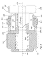
- Fig. 4 is a longitudinal section of a rotation locking mechanism which per se constitutes a first embodiment of the first aspect of the present invention
- Figs. 5 to 13 show individual components of the rotation locking mechanism of Fig. 4
- Figs. 14 & 15 illustrate assembly procedures for certain of these components.
- the respective scales of Figs. 1 to 15 are not mutually identical, though Figs. 5 to 15 have a common scale.
- Fig. 1 is a longitudinal section of a complete torque wrench constituting an embodiment of the second aspect of the present invention
- Fig. 2 is an enlarged-scale detail from Fig. 1 (with Fig. 3 being a cross-section of Fig. 2)
- Fig. 4 is a longitudinal section of a rotation locking mechanism which per
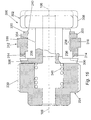
- FIG. 16 is a longitudinal section of a rotation locking mechanism which per se constitutes a second embodiment of the first aspect of the present invention, whereas Figs. 17 to 20 show individual components of the rotation locking mechanism of Fig. 16. Comparison of any particular component or sub-assembly as depicted in Figs. 2 to 15 with that particular component or sub-assembly as shown in Fig. 1 will disclose the correct dimensional scaling factor for comparison with other components and sub-assemblies.
- FIG. 1 this is a longitudinal section of an adjustable torque wrench 100 of a kind similar in general principle (though not identical in detail) to previously known adjustable torque wrenches, for example those disclosed in our published patent applications GB1249590 and EP671243A1.
- the torque wrench 100 comprises a torque-limiting sub-assembly 102, and a handle sub-assembly 104 extending along a longitudinal axis 106 of the wrench 100.
- the sub-assembly 102 includes a tool coupling 108 that is mounted for rotation about an axis 110 at right angles to the longitudinal axis 106.
- the tool coupling is rotationally coupled to a combined rotary cam/ratchet ring 112 that is also rotatably mounted within the sub-assembly 102 for rotation around the axis 110.
- a pawl 114 is mounted for limited sliding movement along the longitudinal axis 106. The pawl 114 is urged against the combined rotary cam/ratchet ring 112 by means of a strong coiled compression spring 116 extending along the axis 106 within the handle sub-assembly 104.
- the force exerted by the spring 116 on the pawl 114 (through a force-transferring member 117) is essentially the force exerted by the pawl 114 on the combined rotary cam/ratchet ring 112, and together with the precise shape of the peripheral profile of the ring 112, determines the maximum torque applicable by the wrench 100 through the tool coupling 108.
- the end of the spring 116 not bearing on the pawl 114 i.e. the right end of the spring 116 as viewed in Fig. 1, bears against an abutment 118 whose position along the axis 106 is adjustable in order to adjust the spring force, and hence to adjust the maximum torque.
- the abutment 118 is coupled by a spacer tube 120 to an end slide 122 that is caused by spring reaction force to bear against a rotatable position controller 124.
- the end of the handle sub-assembly 104 remote from the torque-limiting sub-assembly 102 i.e. the right end of the handle as viewed in Fig.
- the handle housing 126 is also formed with two diametrically opposed and longitudinally extending slots or keyways 132 for a purpose to be detailed subsequently. These keyways 132 are shown in cross-section in Fig. 3, with the outer grip 134 of the handle sub-assembly omitted for clarity.
- the arrangement for adjusting maximum torque so far described is generally known (for example from GB1249590 and EP671243A1), though certain details may be different.
- the present invention is primarily concerned with simply and reliably ensuring that the rotatable position controller 124 is prevented from rotating when the torque wrench 100 is in use, since such unwanted rotation would alter the predetermined maximum torque and thereby render the torque wrench unreliable.
- the rotatable component of the torque wrench 100 constituted by the rotatable position controller 124 is provided with a rotation locking mechanism 200.
- the relationship of the rotation locking mechanism 200 (which constitutes the primary aspect of the present invention) to the remainder of the torque wrench 100 (which constitutes the secondary aspect of the present invention when fitted with the mechanism 200) is shown overall in Fig.
- Fig. 4 separates from the other components of the torque wrench 100, while individual components of the Fig. 4 combination are shown in Figs. 5 to 13. (Taken as a group, Figs. 5, 9, 12, 13, & 6 in succession can be regarded as an exploded view of the Fig. 4 combination).
- the rotatable position controller 124 is formed as a hollow tubular component that is radially enlarged at one end (the left end as viewed in Figs. 4 and 5), this radially enlarged end being externally formed with the previously mentioned screw thread 130 that cooperatively engages with the screw thread 128 formed on the internal surface of the handle housing 126.
- the other end of the position controller 124 is formed with two diametrically opposed and longitudinally extending slots 136 that radially extend through the entire wall thickness of the hollow tubular component 124.
- the slots 136 serve to provide the rotatable position controller 124 with rotational coupling to part of the rotation locking mechanism 200, as will subsequently be detailed.
- a portion 138 of the periphery of the rotatable position controller 124 in the region of the slots 136 is formed with an external diameter that permits relative rotational movement of another part of the mechanism 200, as will also be detailed below.
- a circumferential groove 140 at the outboard end of the portion 138 (the right end as viewed in Figs. 4 and 5) serves as a circlip seating for retention of certain parts of the mechanism 200, as will be explained in due course.
- the rotation locking mechanism 200 is based upon a dog clutch that normally clutches the position controller 124 to a rotation anchor constituted by the handle housing 126, but which can be de-clutched for intentional rotation of the controller 124.
- This dog clutch comprises a first clutch member 202 that appears as part of the assembled mechanism in Figs. 1, 2, and 4, and separately in Figs. 6, 7, and 8. (A second clutch member will subsequently be described with reference to Figs. 9 to 11).
- the first clutch member 202 has a tubular body 204 externally dimensioned to be a clearance fit within the hollow tubular body of the rotatable position controller 124.
- One end of the first clutch member 202 (the left end as viewed in Fig. 6; the near end as viewed in Fig.
- the other end 208 of the first clutch member 202 (the right end as viewed in Fig. 6; the near end as viewed in Fig. 8) is generally disc-shaped with bevelled edges, and has an external diameter that is a clearance fit within the cylindrical interior of the torque wrench handle housing 126 (see Fig. 3).
- the generally disc-shaped end 208 has two opposed flats 210 cut away for rotational keying to a forked adjusting tool (not shown) that is externally applied to engage the first clutch member 202 when rotation of the position controller 124 is intended, this adjusting tool being absent when such rotation is not intended.
- Figs. 9, 10, & 11 show the second clutch member 212, which has a generally annular or ring-like shape.
- the internal diameter of the second clutch member 212 is such as to provide the second clutch member 212 with a rotationally sliding clearance fit on the peripheral region 138 of the rotatable position controller 124.
- One end of the second clutch member 212 (the left end as viewed in Fig. 9; the near end as viewed in Fig. 10) is formed with ten equi-angularly distributed and axially open notches 214.
- Each of the notches 214 radially extends through the full radial thickness of the annular clutch member 212, and each notch 214 is dimensioned to be a sliding fit around the radially projecting keys 206 of the first clutch member 202.
- the other end of the second clutch member 212 (the right end as viewed in Fig. 9; the near end as viewed in Fig. 11) is formed with two diametrically opposed and radially projecting keys 216.
- the keys 216 are dimensioned to be a sliding fit in the longitudinal slots or keyways 132 formed inside the handle housing 126 (refer to Fig. 3).
- the co-operative interaction of the keys 216 and the slots or keyways 132 allow the second clutch member 212 longitudinal movement within the handle housing 126 as required, while rotationally coupling the second clutch member 212 to the handle housing 126 such that relative rotation of the second clutch member 212 and the housing 126 are always prevented. Since it is rotation of the rotatable position controller 124 relative to the handle housing 126 (specifically, rotation of the screw thread 128 relative to the screw thread 130) that adjusts the maximum torque of the torque wrench 100, the above-described rotational coupling of the second clutch member 212 to the housing 126 (by means of the keys 216 and the keyways 132) causes the second clutch member 212 to function as the rotation anchor of the rotation locking mechanism 200.
- the rotation locking mechanism 200 is assembled by first emplacing the first clutch member 202, key end first, inside the end of the hollow tubular component 124, with the keys 206 radially projecting through the slots 136.
- the second clutch member 212 is placed around the peripheral region 138 of the component 124, with the notches 214 towards the keys 216 of the previously installed first clutch member 202.
- a washer 220 (shown separately in Fig. 12) follows the second clutch member 212, and this assemblage of parts is held together by a circlip 230 (shown separately in Fig. 13) emplaced in the circlip groove 140.
- the second clutch member 212 is then installed on the first clutch member 202 by a procedure similar to that described with reference to Fig. 14, as depicted in Fig. 15 (from which the previously installed circlip 230 and washer 220 have been omitted for clarity).
- the parts of the rotation locking mechanism 200 (comprising the first clutch member 202 "preloaded" with the second clutch member 212, the washer 220, and the circlip 230) are then coupled to the rotatable position controller 124 to form the assembly shown in Fig. 4.
- Fig. 4 (which shows the rotation locking mechanism 200 assembled and coupled to the rotatable position controller 124) also schematically (and incompletely) depicts a coiled compression spring 240 disposed within the hollow interior of the component 124.
- the spring 240 serves to urge the first clutch member 202 rightwards (as viewed in Fig. 4) with respect to the rotatable position controller 124 to which the first clutch member 202 is rotationally coupled by means of the previously detailed keys 216 and slots 136.
- the keys 206 engage with an opposed pair of the notches 214 such that the first and second clutch members 202 and 212 are clutched together so as positively to prevent their relative rotation.
- the first clutch member 202 has been moved leftwards (as viewed in Fig. 4) with respect to the controller 124 by the external application to the part 208 of the previously described adjustment tool (not shown), for which purpose the end closure 142 of the torque wrench handle sub-assembly 104 is temporarily removed.
- External application of the adjusting tool is initially along the longitudinal axis 106, through the hollow tubular interior of the handle sub-assembly 104, and against the first clutch member 202 initially to move the member 202 longitudinally against the spring 240.
- the rotatable position controller 124 is controllably moved along the axis 106 relative to the housing 126, in turn causing or allowing corresponding repositioning of the end slide 122, the spacer tube 120, and the abutment 118, with a corresponding change in the length of the spring 116.
- the maximum torque of the torque wrench 100 is controllably adjusted by an amount that is directly controlled by the rotational direction and rotational extent of movement of the adjusting tool.
- first clutch member 202 is permanently rotationally coupled to the rotatable position controller 124 (as previously explained) while the second clutch member 212 is permanently rotationally anchored to the housing 126 (as previously explained)
- withdrawal of the externally applied adjusting tool not only causes re-engagement of the two dog clutch members 202 and 212, but also rotationally locks the rotatable position controller 124 against further rotation (unless and until the external adjusting tool is re-applied).
- the rotation locking mechanism 200 renders the torque wrench 100 highly resistant to disturbance of the setting of its maximum torque by vibration and shock.
- Provision of the second clutch member 212 with ten equi-angularly spaced notches 214 allows the position controller 124 to be rotated in steps of 36o, and use of other numbers of notches will allow rotational adjustment in correspondingly sized angular steps.
- For rotational coupling use of suitable arrangements of keys and slots in other than diametrically opposed pairs is optional. Means of rotational coupling other than keys and slots may be employed in place of those described above. Suitable bias means other than the spring 240 can be utilised for biasing the two clutch members into mutual engagement.
- the member 202 can be adapted for operative application of cheaper non-dedicated tools, e.g. if the risk of unauthorised adjustment is considered to be acceptable as against the increased security provided by the necessary utilisation of a unique tool.
- Suitable clutch means other than dog clutches can be employed as part of the rotation locking mechanism of the invention.
- FIG. 16 to 20 A second embodiment of the first aspect of the present invention is shown in Fig. 16 to 20.
- the rotation locking mechanism 300 is similar in general principle to the embodiment described above, and except as otherwise stated parts labelled '3xx' in Figs. 16 to 20 are equivalent to parts labelled '2xx' in Figs. 1 to 15.
- the main difference is in the form of the clutch assembly.
- the clutch assembly is based upon a dog clutch, in that the radially projecting keys 206 of the first clutch member 202 are a sliding fit into the notches 214 of the second clutch member 212.
- To disengage the clutch assembly to allow relative movement of the first and second clutch members 202,212 requires an axial force to be exerted on the first clutch member 202 against the spring 240 as detailed above.
- the projecting keys 306 of the first clutch member 302 are not cuboidal form, but of substantially pentagonal prism shape.
- the keys 306 are effectively shaped to have a triangular prism mating face, the apex of which directs toward the end 308 of the first clutch member 302.
- the notches 314 of the second clutch member 312 are also of a corresponding triangular cut out shape, the angle of both being 120o.
- the axial force required to disengage the first and second clutch members 302,312 can be significantly reduced or dispensed with entirely. If a purely rotational force is applied to the first clutch member 302, the angled form of the keys 306 and notches 314 allows the two clutch members to slip in relation to each other. The resilience of the spring 340 urges the first clutch member 302 against the second 312 such that when sufficient rotation is applied to the first clutch member 302, the keys 306 will move to the next set of notches 314 and engage therewith. Continued rotation allows the keys 306 to engage with the next set of notches 314 and so forth.
Landscapes
- Engineering & Computer Science (AREA)
- Mechanical Engineering (AREA)
- Details Of Spanners, Wrenches, And Screw Drivers And Accessories (AREA)
Abstract
Description
Claims (11)
- A rotation locking mechanism for locking a selectively rotatable component against unwanted rotation thereof while permitting wanted rotation thereof, the rotatable component comprising rotation application means for selective application of wanted rotation to the rotatable component by external engagement with the rotation application means, the rotation locking mechanism comprising clutch means coupling the rotatable component to a rotation anchor by way of the clutch means, the clutch means being normally engaged to clutch the rotatable component to the rotation anchor whereby to anchor the rotatable component against unwanted rotation and the clutch means being able to temporarily disengage to unlock the rotatable component for intended rotation.
- A rotation locking mechanism according to Claim 1 wherein the clutch means is disengaged by external engagement with the rotation application means.
- A rotation locking mechanism according to Claims 1 or 2 wherein the clutch means comprises a clutch having a rotation axis together with first and second clutch members that are relatively rotatable about the rotation axis.
- A rotation locking mechanism according to Claim 3 wherein the first and second clutch members are formed to mutually lock against relative rotation when axially engaged and to mutually unlock to permit relative rotation when axially disengaged.
- A rotation locking mechanism according to Claims 3 and 4 wherein the first clutch member of the clutch is rotationally coupled to the rotatable component for conjoint rotation therewith, while the second clutch member of the clutch is rotationally coupled to the rotation anchor.
- A rotation locking mechanism according to any of Claims 2 to 5 wherein the clutch has bias means biasing the first and second clutch members into axial engagement to lock the first and second clutch members against relative rotation, such biasing being temporarily overcome by the external engagement with the rotation application means.
- A rotation locking mechanism according to Claim 6 wherein the bias means is a coiled compression spring that is substantially coaxial with the rotation axis of the clutch.
- A rotation locking mechanism according to any of Claims 2 to 7 wherein rotational coupling of the first clutch member to the rotatable component is by at least one radially projecting key on one of the first clutch member and the rotatable component slidingly engaging with at least one longitudinally extending slot in the other of the first clutch member and the rotatable component.
- A rotation locking mechanism according to any preceding claim wherein the rotation anchor comprises a housing of the rotatable component.
- A rotation locking mechanism according to Claim 9 wherein rotational coupling of the second clutch member to such housing serving as the rotation anchor is by means of at least one radially projecting key on one of the second clutch member and said casing or housing slidingly engaging with at least one longitudinally extending slot formed in the other of the second clutch member and the interior surface of said housing.
- An adjustable torque wrench of the type whose maximum torque application value is controlled by way of a compressible coil spring wherein the compressible coil spring's compression is controlled by selectable adjustment means, the selectable adjustment means including a rotation locking mechanism according to any preceding claim.
Applications Claiming Priority (4)
| Application Number | Priority Date | Filing Date | Title |
|---|---|---|---|
| GB0103372 | 2001-02-10 | ||
| GB0103372A GB0103372D0 (en) | 2001-02-10 | 2001-02-10 | Rotation Locking Mechanism |
| GB0130879A GB0130879D0 (en) | 2001-02-10 | 2001-12-24 | Rotation locking mechanism |
| GB0130879 | 2001-12-24 |
Publications (2)
| Publication Number | Publication Date |
|---|---|
| EP1231026A2 true EP1231026A2 (en) | 2002-08-14 |
| EP1231026A3 EP1231026A3 (en) | 2004-02-11 |
Family
ID=26245707
Family Applications (1)
| Application Number | Title | Priority Date | Filing Date |
|---|---|---|---|
| EP02250869A Withdrawn EP1231026A3 (en) | 2001-02-10 | 2002-02-08 | Rotation locking mechanism |
Country Status (1)
| Country | Link |
|---|---|
| EP (1) | EP1231026A3 (en) |
Family Cites Families (4)
| Publication number | Priority date | Publication date | Assignee | Title |
|---|---|---|---|---|
| US3581606A (en) * | 1969-05-23 | 1971-06-01 | Bosco Grabovac | Torque wrench |
| US4063474A (en) * | 1975-11-06 | 1977-12-20 | Dresser Industries, Inc. | Torque limiting screwdriver |
| SE470449B (en) * | 1992-08-31 | 1994-04-11 | Sandvik Ab | Lockable spring tensioning device |
| US6095020A (en) * | 1999-01-11 | 2000-08-01 | Beere Precision Medical Instruments, Inc. | Hand tool having a variable torque-limiting in-line drive |
-
2002
- 2002-02-08 EP EP02250869A patent/EP1231026A3/en not_active Withdrawn
Also Published As
| Publication number | Publication date |
|---|---|
| EP1231026A3 (en) | 2004-02-11 |
Similar Documents
| Publication | Publication Date | Title |
|---|---|---|
| US3958469A (en) | Torque wrench | |
| US5352071A (en) | Hole saw arbor with retaining mechanism | |
| US7757374B2 (en) | Keyless chuck with automatic and manual locking | |
| US9999966B2 (en) | Torque wrench | |
| US5653605A (en) | Locking coupling | |
| US6527314B2 (en) | Clutch handle | |
| CA2639679C (en) | Adjustable bent housing with rotational stop | |
| EP0775036B1 (en) | Quick release mechanism for tools such as socket wrenches | |
| US11085720B2 (en) | Safety selector assembly and associated accessories | |
| GB2149883A (en) | Shaft coupling | |
| US5143286A (en) | Thermostatic valve | |
| TWI759910B (en) | Indexable ratchet tool and connecting pin | |
| AU2024201916A1 (en) | Hub for ratchet gears | |
| US20060008339A1 (en) | Screw-nut assembly having an integrated,immediately effective safeguarding against unintentional loosening of a screw connection formed therewith | |
| US10702979B2 (en) | Torque adjustment device for torque wrench | |
| US6263541B1 (en) | Winding cone of an overhead door counterbalancing mechanism and torsion spring winding method therefor | |
| US10267294B2 (en) | Spring return device | |
| US20180073270A1 (en) | Lock Apparatus | |
| EP3443252B1 (en) | Camlock | |
| GB2254103A (en) | Locking mechanism for a valve | |
| US20250042007A1 (en) | Locking member for adjustable torque wrench | |
| US20060162221A1 (en) | Locking device for a firearm | |
| US11466723B2 (en) | Nut-locking device and associated assembly unit | |
| US11629746B2 (en) | Nut-locking device and associated assembly unit | |
| JPH0694887B2 (en) | Adjustable torque limiting assembly |
Legal Events
| Date | Code | Title | Description |
|---|---|---|---|
| PUAI | Public reference made under article 153(3) epc to a published international application that has entered the european phase |
Free format text: ORIGINAL CODE: 0009012 |
|
| AK | Designated contracting states |
Kind code of ref document: A2 Designated state(s): AT BE CH CY DE DK ES FI FR GB GR IE IT LI LU MC NL PT SE TR |
|
| AX | Request for extension of the european patent |
Free format text: AL;LT;LV;MK;RO;SI |
|
| PUAL | Search report despatched |
Free format text: ORIGINAL CODE: 0009013 |
|
| AK | Designated contracting states |
Kind code of ref document: A3 Designated state(s): AT BE CH CY DE DK ES FI FR GB GR IE IT LI LU MC NL PT SE TR |
|
| AX | Request for extension of the european patent |
Extension state: AL LT LV MK RO SI |
|
| RIC1 | Information provided on ipc code assigned before grant |
Ipc: 7F 16B 1/04 B Ipc: 7B 25B 23/142 B Ipc: 7B 25B 23/14 A |
|
| AKX | Designation fees paid | ||
| REG | Reference to a national code |
Ref country code: DE Ref legal event code: 8566 |
|
| STAA | Information on the status of an ep patent application or granted ep patent |
Free format text: STATUS: THE APPLICATION IS DEEMED TO BE WITHDRAWN |
|
| 18D | Application deemed to be withdrawn |
Effective date: 20040901 |