EP1230751B1 - Method and system for maintaining uplink synchronization in cdma based mobile communication systems - Google Patents
Method and system for maintaining uplink synchronization in cdma based mobile communication systems Download PDFInfo
- Publication number
- EP1230751B1 EP1230751B1 EP00964247A EP00964247A EP1230751B1 EP 1230751 B1 EP1230751 B1 EP 1230751B1 EP 00964247 A EP00964247 A EP 00964247A EP 00964247 A EP00964247 A EP 00964247A EP 1230751 B1 EP1230751 B1 EP 1230751B1
- Authority
- EP
- European Patent Office
- Prior art keywords
- actual
- mobile station
- reception
- command
- base station
- Prior art date
- Legal status (The legal status is an assumption and is not a legal conclusion. Google has not performed a legal analysis and makes no representation as to the accuracy of the status listed.)
- Expired - Lifetime
Links
- 238000000034 method Methods 0.000 title claims description 25
- 238000010295 mobile communication Methods 0.000 title claims description 17
- 230000011664 signaling Effects 0.000 claims description 18
- 230000007423 decrease Effects 0.000 claims description 15
- 238000005259 measurement Methods 0.000 claims description 15
- 238000004891 communication Methods 0.000 claims description 13
- 230000003247 decreasing effect Effects 0.000 claims description 10
- 230000004044 response Effects 0.000 claims description 4
- 230000005540 biological transmission Effects 0.000 description 8
- 238000010586 diagram Methods 0.000 description 6
- 238000012423 maintenance Methods 0.000 description 3
- 230000004048 modification Effects 0.000 description 2
- 238000012986 modification Methods 0.000 description 2
- 230000001360 synchronised effect Effects 0.000 description 2
- 238000004364 calculation method Methods 0.000 description 1
- 230000008859 change Effects 0.000 description 1
- 230000000694 effects Effects 0.000 description 1
- 238000005516 engineering process Methods 0.000 description 1
- 238000005562 fading Methods 0.000 description 1
- 230000008569 process Effects 0.000 description 1
- 230000009467 reduction Effects 0.000 description 1
- 238000001228 spectrum Methods 0.000 description 1
- 230000007480 spreading Effects 0.000 description 1
Images


Classifications
-
- H—ELECTRICITY
- H04—ELECTRIC COMMUNICATION TECHNIQUE
- H04J—MULTIPLEX COMMUNICATION
- H04J13/00—Code division multiplex systems
-
- H—ELECTRICITY
- H04—ELECTRIC COMMUNICATION TECHNIQUE
- H04B—TRANSMISSION
- H04B7/00—Radio transmission systems, i.e. using radiation field
- H04B7/24—Radio transmission systems, i.e. using radiation field for communication between two or more posts
- H04B7/26—Radio transmission systems, i.e. using radiation field for communication between two or more posts at least one of which is mobile
- H04B7/2662—Arrangements for Wireless System Synchronisation
- H04B7/2668—Arrangements for Wireless Code-Division Multiple Access [CDMA] System Synchronisation
-
- H—ELECTRICITY
- H04—ELECTRIC COMMUNICATION TECHNIQUE
- H04W—WIRELESS COMMUNICATION NETWORKS
- H04W56/00—Synchronisation arrangements
- H04W56/0005—Synchronisation arrangements synchronizing of arrival of multiple uplinks
-
- H—ELECTRICITY
- H04—ELECTRIC COMMUNICATION TECHNIQUE
- H04B—TRANSMISSION
- H04B7/00—Radio transmission systems, i.e. using radiation field
- H04B7/24—Radio transmission systems, i.e. using radiation field for communication between two or more posts
- H04B7/26—Radio transmission systems, i.e. using radiation field for communication between two or more posts at least one of which is mobile
- H04B7/2662—Arrangements for Wireless System Synchronisation
- H04B7/2671—Arrangements for Wireless Time-Division Multiple Access [TDMA] System Synchronisation
- H04B7/2678—Time synchronisation
- H04B7/2681—Synchronisation of a mobile station with one base station
-
- H—ELECTRICITY
- H04—ELECTRIC COMMUNICATION TECHNIQUE
- H04J—MULTIPLEX COMMUNICATION
- H04J3/00—Time-division multiplex systems
- H04J3/02—Details
- H04J3/06—Synchronising arrangements
- H04J3/0635—Clock or time synchronisation in a network
- H04J3/0682—Clock or time synchronisation in a network by delay compensation, e.g. by compensation of propagation delay or variations thereof, by ranging
Definitions
- the present invention relates to CDMA technology, in particular, a method and system for maintenance of UL synchronization in CDMA based mobile communication systems.
- the uplink channels are asynchronous. That means the signals of the users arrive at the serving Node B (the Base Station) at different time. So the asynchronous spreading codes used by different users (for example PN (pseudo noise) sequence) will interfere each other. That interference is known as Multi-Access-Interference. Since CDMA is an interference-limited system, any additional interference will result in capacity reduction. Uplink synchronization or so-called synchronous CDMA system keeps all user signals reaching the base station at the same time. It will greatly reduce Multi-Access-Interference. Thus uplink synchronization (US) will lead to higher capacity and simplify the demodulator in Node B at the base station side.
- PN pseudo noise
- Synchronization is more difficult to realize in mobile communications system because of the multi-path and shadow fading characteristic of mobile channel. Since the channel characteristic varies in time frequently and the accuracy for uplink (UL) synchronization must be high, the update frequency of the mobile's transmission TX timing must be fast. The problem is how to find an effective way to realize uplink synchronization and keep the system spending acceptable.
- the realization of UL synchronization can be divided into two parts: UL synchronization establishment and UL synchronization maintenance. In the invention a simple and effective method to maintain the uplink synchronization is described.
- Fig. 1 illustrates a schematic diagram of the timing advance scheme. As shown in Fig. 1, there is a propagation delay when the BS receives the UL transmission signal. Therefore, a timing advance is provided to the burst during UL transmission at the mobile station (MS) site, so that the burst received at the BS can be just in time.
- MS mobile station
- the timing advance information is transmitted from layer 3. Since the accuracy for UL synchronization is higher and the update frequency is faster than timing advance, the timing advance scheme cannot meet the requirement of UL synchronization. In current mobile communications system, there is no solution for UL synchronization. Hence before the invention, the problem is open.
- US 5,446,727 discloses a method and apparatus for time aligning signals for reception in a CDMA communications system, where upon reception of a signal from a subscriber unit a base station will compare the time of arrival of the received signal with a reference value and then transmit in turn a signal containing time alignment information to the subscriber unit.
- EP 0 673 130 discloses a method for establishing synchronisation in a CDMA communications system between a base station and mobile users.
- the base station transmits a signal to the mobile users in which it has inserted a signal representative of the propagation delay and a propagation delay increment. Upon receiving this information the mobile users will adjust their spread spectrum patterns.
- US 5,229,996 discloses a method for correcting time misalignment in communications between mobile stations and a base station. Synchronisation is maintained by detecting time misalignments in received communications and then providing time adjustments and then checking during two discontinuous time intervals to see whether the provided time adjustments were implemented.
- One object of the invention is to provide a method and system for maintenance of UL synchronization in CDMA based mobile communication systems with -high accuracy and fast update frequency, thereby reducing multi-access-interference effectively, achieving higher capacity of the CDMA system.
- a further object of the invention is to provide a communication system utilizing the above method, and the base station and mobile station thereof.
- the present invention provides a method for maintaining uplink synchronization in a mobile communication system, said mobile communication system comprising a base station, and at least one mobile station, the method comprising the steps of:
- the present invention further provides a system for maintaining uplink synchronization in mobile communication system, said mobile communication system comprising a base station, at least one mobile station, said system comprising: receiving means for receiving signals transmitted by one of said mobile station; measuring means for measuring timing of the transmitted signals from the mobile station and obtaining US Actual value currently used in the mobile station; calculating means for calculating a US Target value based on the measurement; comparing means for comparing US Actual and US Target to generate a SS command for increasing or decreasing said US Ac- tual ; signaling means for signaling said synchronization shift (SS) command in downlink to said mobile station to increase or decrease said US Actual. .
- SS synchronization shift
- the present invention further provides a mobile communication system, comprising:
- the present invention further provides a base station in a mobile communication system, comprising:
- the present invention further provides a mobile communication system, comprising: a base station; at least one mobile station; wherein said base station comprises: receiving means for receiving signals transmitted by one of said mobile station; measuring means for measuring timing of the transmitted signals from the mobile station and obtaining US Actual value currently used in the mobile station; calculating means for calculating a US Target value based on the measurement; comparing means for comparing US Actual and US Target to generate a SS command for increasing or decreasing said US Actual ; signaling means for signaling said synchronization shift (SS) command in downlink to said mobile station to increase or decrease said US Actual , and wherein said mobile station comprises: adjusting means for increase or decrease said US Actual according to said synchronization shift command, as well as the base station and mobile station used therein.
- a base station comprises: receiving means for receiving signals transmitted by one of said mobile station; measuring means for measuring timing of the transmitted signals from the mobile station and obtaining US Actual value currently used in the mobile station; calculating means for calculating a US Target value based on the measurement; comparing means for
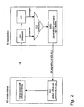
- Fig. 2 illustrates a schematic diagram of the CDMA system according to one embodiment of the present invention.
- the base station receives the signals transmitted in uplink from the mobile station.
- the base station includes a measurement unit MU for measuring the timing of the received signals, and obtaining a US Actual , which is a US value (equivalent to a timing advance) currently used by the mobile station; a uplink synchronization control unit UC for calculating a US Target , which is defined as exactly that value that would be optimal for UL synchronization; a compare unit CU for comparing the US Actual with the US Target ; and a SS command generating unit SSU for generating a SS command according to the comparison result.
- a measurement unit MU for measuring the timing of the received signals, and obtaining a US Actual , which is a US value (equivalent to a timing advance) currently used by the mobile station
- a uplink synchronization control unit UC for calculating a US Target , which is defined as exactly that value that
- the SS command is downlink signaled in Layer 1 L1 to the mobile station MS to adjust, increase or decrease the US Actual value used in the MS.
- the base station also includes a receiving means (not shown) for receiving signals transmitted from the MS; and a signaling means (not shown) for transmitting signals having the SS commands in downlink to the MS. They can be a known receiver or transmitter, thereby the details thereof are not described in this application.
- the transmission unit in the MS transmits signals with the US Actual timing, and the adjustment unit AU in the MS adjusts the US Actual value according to the SS commands.
- a new L1 layer 1 signaling SS (synchronization shift) is used to maintain UL synchronization
- the SS commands are transmitted in the downlink of the physical layer.
- the measurement unit in the serving node B or base station continuously measures the timing of a transmission from the user equipment, i.e., the mobile station MS. Then, based on these measurements, the UL synchronization Control UC unit calculates the US Target .
- the US Target is defined as exactly that value that would be optimal for UL synchronization.
- the US value that is currently used by the system is defined as US Actual .
- the SS command is generated by the relationship between US Ac-tual and US Target and is used to increase or decrease US Actual .
- the SS is up- or down-command and does not signal the US Target itself.
- the US Actual is changed in steps according to SS commands and one (single stepsize) or more (multiple stepsizes) predefined stepsize. The smallest stepsize is equivalent to the necessary accuracy of UL synchronization.
- the process of the UL synchronization control may includes the following steps: Synchronization Control unit UC calculates a US Target; SS command is generated by comparing of US Actual and US Target , wherein SS is an up- or down-command; SS command is used by the MS to increase or decrease US Actual in predefined step(s), which are known in advance and/or are encoded in the SS command; SS command is signaled in layer 1 L1 (SS field in Burst) to achieve the high update frequency of US.
- the required accuracy for UL synchronization is, for example, ⁇ 1/8chips.
- the serving node B at the BS side continuously measures the timing of a transmission from the MS, obtains the US Actual , and calculates a US Target . Based on the comparison of the US Actual and the US Target , SS commands are generated and signaled in DL.
- the US Actual used in MS is changed in steps according to SS commands, and changed one (single stepsize) or more (multiple stepsizes) predefined stepsizes.
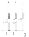
- Fig. 3 illustrates a schematic diagram for explaining the calculation of the US Target in the UL synchronization control unit UC according to the invention.
- the UC has the purpose of calculating the US target . Because of the multipath effect and the time variance of the channel, a perfect UL synchronization cannot be established. Therefore the US target has the purpose to find that timing for UL transmission, where the performance of US is optimal. Two basic methods are possible, one is slow UC, the other is fast UC.
- Fig. 3 As shown in Fig. 3, from the bottom to the top, there are three bursts (for exemplary purpose) in time sequence transmitted from the MS are received at the BS. For each of the burst, the BS receives corresponding taps of impulse response IR. Since the MS is moving and is in a time variant environment, the IR at the BS side is varied in time and in power, as shown in Fig. 3.
- the US target is equivalent to the propagation delay plus the delay of that tap in the IR, that has the highest power in average.
- This method additionally includes the average characteristics of the mobile station's IR. Therefore the UC must know the statistics of the IR.
- the US target is equivalent to the propagation plus the delay of that tap in the IR, that has actually the highest power. This method should provide the best performance of US, however the US target will rapidly change, which causes more frequent signaling of SS commands in the DL.
- the smallest stepsize is equivalent to the necessary accuracy, for example, 1/8 Chips.
- the stepsize can be a fixed value pre-set in the MS. It is also possible for the BS to broadcast the stepsize to the respective mobile stations, and each of the MSs use the received stepsize to increase or decrease its US Actual value.
- the SS commands are transmitted in the physical layer, i.e., L1-signaling.
- the SS information is one bit. More bits can be used for multiple stepsizes or error protection. Since SS commands are signaled in L1, they need a special field in the burst. The SS field is only added in DL timeslots because the transmission of SS is only needed in DL.
- Fig. 4 and Fig.5 shows two examples of the position of the synchronization shift command SS in a traffic burst, according to the present invention.
- SS field As shown in Fig. 4, in this example, one symbol (two bits) for SS field is reserved.
- the SS field is placed around the midamble in order to achieve effective protection in time-variant environments.
- the reason for placing the SS command near the midamble is that the above measurement is made at the midamble, so that the adjustment of the US value at the MS can be more based on the real US status and more efficiently.
- the SS information is transmitted every frame in DL physical channel.
- Fig.4 shows the position of SS in traffic DL burst for UTRA (UMTS(Universal Mobile Telecommunication System) terrestrial radio access) -TDD(Time Division Duplex) system.
- UTRA Universal Mobile Telecommunication System
- TFCI Transport Format Combination Indicator
- SS is transmitted directly adjacent to the TFCI.
- Fig. 5 shows the position of SS in traffic DL burst when TFCI is transmitted.
- ⁇ US is single stepsize for the modification of US.
- ⁇ US is equal to 1/8 chips and it is predefined in the system.
- the present invention provide an effective method to maintain the uplink synchronization in CDMA based mobile communication systems with high accuracy and fast update frequency. And consequently, it will greatly reduce multi-access-interference, and lead to higher capacity of the CDMA system as well as simplify the demodulator at the base station side.
Landscapes
- Engineering & Computer Science (AREA)
- Computer Networks & Wireless Communication (AREA)
- Signal Processing (AREA)
- Mobile Radio Communication Systems (AREA)
- Synchronisation In Digital Transmission Systems (AREA)
Description
- receiving means for receiving signals transmitted by said mobile station;
- measuring means for measuring an actual time of reception (USActual) of the transmitted signals from the mobile station;
- calculating based on said measurements an optimal time of reception (USTarget), which is defined as being optimal for uplink synchronization;
- comparing means for comparing said actual time of reception (USActual) and said optimal time of reception (USTarget) and for generating a synchronization shift (SS) command for increasing or decreasing an actual uplink timing advance used in the mobile station;
- signaling means for signaling said synchronization shift (SS) command in a downlink physical layer burst to said mobile station to increase or decrease said actual uplink timing advance, and
- adjusting means for increase or decrease said actual uplink timing advance according to said synchronization shift command (SS),
wherein said mobile station comprises: adjusting means for increase or decrease said USActual according to said synchronization shift command, as well as the base station and mobile station used therein.
If USActual > USTarget , then the SS=0;
If USActual < USTarget , then the SS=1;
Claims (21)
- A method for maintaining uplink synchronization in a mobile communication system, said mobile communication system comprising a base station, and at least one mobile station, the method comprising the steps of:receiving at said base station signals transmitted by said mobile station;measuring at said base station an actual time of reception (USActual) of the transmitted signals from the mobile station;calculating based on said measurements an optimal time of reception (USTarget), which is defined as being optimal for uplink synchronization;comparing at said base station said actual time of reception (USActual) and said optimal time of reception (USTarget) to generate a synchronization shift (SS) command for increasing or decreasing an actual uplink timing advance used in said mobile station;signalling at said base station said synchronization shift (SS) command in a downlink physical layer burst to said mobile station to increase or decrease said actual uplink timing advance, wherein said synchronization shift (SS) command is placed around the midamble in said signalled burst.
- The method according to claim 1, wherein said measurement is made at the midamble.
- The method according to claim 1, wherein said synchronization shift (SS) command is transmitted every frame in a physical channel.
- The method according to claim 1, wherein the channel statistics is used to calculate said optimal time of reception (USTarget) in said calculating step.
- The method according to claim 1, wherein a tap in impulse response having actually the highest power is used to determine said optimal time of reception (USTarget) in said calculating step.
- The method according to claim 1, wherein said mobile station increases or decreases the actual uplink timing advance according to said synchronization shift (SS) command in a predetermined stepsize or stepsizes.
- The method according to claim 6, wherein said stepsize is a fixed value preset in said mobile station.
- The method according to claim 7, wherein said mobile station receives the stepsize broadcasted from said base station.
- A mobile communication system, comprising:wherein said base station comprises:a base station;at least one mobile station;wherein said mobile station comprises:receiving means for receiving signals transmitted by said mobile station;measuring means for measuring an actual time of reception (USActual) of the transmitted signals from the mobile station;calculating based on said measurements an optimal time of reception (USTarget), which is defined as being optimal for uplink synchronization;comparing means for comparing said actual time of reception (USActual) and said optimal time of reception (USTarget) and for generating a synchronization shift (SS) command for increasing or decreasing an actual uplink timing advance used in the mobile station;signaling means for signaling said synchronization shift (SS) command in a downlink physical layer burst to said mobile station to increase or decrease said actual uplink timing advance, andcharacterised in that said synchronization shift (SS) command is placed around the midamble in said signalled burst.adjusting means for increasing or decreasing said actual uplink timing advance according to said synchronization shift command (SS),
- The communication system according to claim 9, wherein said measurement is made at the midamble.
- The communication system according to claim 9, wherein said synchronization shift (SS) command is transmitted every frame in a physical channel.
- The communication system according to claim 9, wherein the channel statistics is used to calculate said optimal time of reception (USTarget) in said calculating step.
- The communication system according to claim 9, wherein a tap in impulse response having actually the highest power is used to determine said optimal time of reception (USTarget) in said calculating step.
- The communication system according to claim 9, wherein said mobile station includes an adjusting means for increasing or decreasing said actual uplink timing advance according to said synchronization shift (SS) command in a predetermined stepsize or stepsizes.
- The communication system according to claim 14, wherein said stepsize is a fixed value preset in said mobile station.
- The communication system according to claim 15, wherein said mobile station receives the stepsize broadcasted from said base station.
- A base station in a mobile communication system, comprising:receiving means for receiving signals transmitted from at least one mobile station;measuring means for measuring an actual time of reception (USActual) of the transmitted signals from said least one mobile station;calculating based on said measurements an optimal time of reception (USTarget), which is defined as being optimal for uplink synchronization;comparing means for comparing said actual time of reception (USActual) and said optimal time ofreception (USTarget) and for generating a synchronization shift (SS) command for increasing or decreasing an actual uplink timing advance used in said least one mobile station;signaling means for signaling said synchronization shift (SS) command in a downlink physical layer burst to said least one mobile station to increase or decrease said actual uplink timing advance, characterised in that said synchronization shift (SS) command is placed around the midamble in said signalled burst.
- The base station according to claim 17, wherein said measurement is made at the midamble.
- The base station according to claim 18, wherein said synchronization shift (SS) command is transmitted every frame in a physical channel.
- The base station according to claim 19, wherein the channel statistics is used to calculate said optimal time of reception (USTarget) in said calculating step.
- The base station according to claim 17, wherein a tap in impulse response having actually the highest power is used to determine said optimal time of reception (USTarget) in said calculating step.
Applications Claiming Priority (3)
| Application Number | Priority Date | Filing Date | Title |
|---|---|---|---|
| CN99122482 | 1999-09-28 | ||
| CNB991224825A CN1154269C (en) | 1999-09-28 | 1999-09-28 | Method and system for maintaining uplink synchronization in code division multiple access mobile communication system |
| PCT/EP2000/009517 WO2001024411A1 (en) | 1999-09-28 | 2000-09-28 | Method and system for maintaining uplink synchronization in cdma based mobile communications systems |
Publications (2)
| Publication Number | Publication Date |
|---|---|
| EP1230751A1 EP1230751A1 (en) | 2002-08-14 |
| EP1230751B1 true EP1230751B1 (en) | 2005-06-22 |
Family
ID=5282501
Family Applications (1)
| Application Number | Title | Priority Date | Filing Date |
|---|---|---|---|
| EP00964247A Expired - Lifetime EP1230751B1 (en) | 1999-09-28 | 2000-09-28 | Method and system for maintaining uplink synchronization in cdma based mobile communication systems |
Country Status (5)
| Country | Link |
|---|---|
| EP (1) | EP1230751B1 (en) |
| JP (1) | JP2003510953A (en) |
| CN (1) | CN1154269C (en) |
| DE (1) | DE60020990T2 (en) |
| WO (1) | WO2001024411A1 (en) |
Families Citing this family (26)
| Publication number | Priority date | Publication date | Assignee | Title |
|---|---|---|---|---|
| US8537656B2 (en) * | 2000-07-19 | 2013-09-17 | Ipr Licensing, Inc. | Method for compensating for multi-path of a CDMA reverse link utilizing an orthogonal channel structure |
| US7911993B2 (en) | 2000-07-19 | 2011-03-22 | Ipr Licensing, Inc. | Method and apparatus for allowing soft handoff of a CDMA reverse link utilizing an orthogonal channel structure |
| KR100762594B1 (en) | 2001-06-23 | 2007-10-01 | 엘지전자 주식회사 | Synchronous Control Method of Uplink Signal |
| US6917581B2 (en) | 2001-07-17 | 2005-07-12 | Ipr Licensing, Inc. | Use of orthogonal or near orthogonal codes in reverse link |
| GB2381161B (en) * | 2001-10-19 | 2005-07-27 | Roke Manor Research | A communication method and apparatus |
| AU2003303841A1 (en) * | 2003-01-27 | 2004-08-23 | Linkair Communications, Inc. | A method and an apparatus of uplink synchronization acquisition |
| CN1527622A (en) * | 2003-03-07 | 2004-09-08 | �ʼҷ����ֵ��ӹɷ�����˾ | Method and apparatus for up-link hold-in of point-to-point coordinate communication in radio communication network |
| JP2007227986A (en) * | 2004-02-02 | 2007-09-06 | Nec Corp | Wireless access system |
| CN101243622B (en) * | 2005-10-21 | 2012-05-30 | 中兴通讯股份有限公司 | Uplink signal transmitting method of user equipment and method for timing synchronization of uplink signal transmitting method |
| CN101185270B (en) * | 2005-11-16 | 2010-10-13 | 中兴通讯股份有限公司 | Uplink synchronization method in mobile communication system |
| KR101161918B1 (en) | 2006-03-24 | 2012-07-03 | 인터디지탈 테크날러지 코포레이션 | Method and apparatus for maintaining uplink synchronization and reducing battery power consumption |
| CN101094029B (en) * | 2006-06-21 | 2012-06-06 | 中兴通讯股份有限公司 | Synchronization control method of reversed shared channel in time division synchronous code division multiple access system |
| CN101154984B (en) * | 2006-09-25 | 2012-10-03 | 电信科学技术研究院 | Method and system for remaining ascending synchronization |
| EP1909409A1 (en) * | 2006-10-04 | 2008-04-09 | Nokia Siemens Networks Gmbh & Co. Kg | Method for controlling the timing of uplink signal transmission in a radiocommunication system |
| US8571006B2 (en) * | 2007-04-24 | 2013-10-29 | Ntt Docomo, Inc. | Mobile communication method and radio base station |
| KR101486352B1 (en) | 2007-06-18 | 2015-01-26 | 엘지전자 주식회사 | Method of controlling uplink synchronization state at a user equipment in a mobile communication system |
| KR101341515B1 (en) | 2007-06-18 | 2013-12-16 | 엘지전자 주식회사 | Method of updating repeatedly-transmitted information in wireless communicaiton system |
| KR101490253B1 (en) | 2007-08-10 | 2015-02-05 | 엘지전자 주식회사 | Method of transmitting and receiving control information in a wireless communication system |
| KR101591824B1 (en) | 2007-09-18 | 2016-02-04 | 엘지전자 주식회사 | Method of performing polling procedure in a wireless communication system |
| KR101513033B1 (en) | 2007-09-18 | 2015-04-17 | 엘지전자 주식회사 | A method for qos guarantees in a multilayer structure |
| KR101594359B1 (en) | 2008-01-31 | 2016-02-16 | 엘지전자 주식회사 | Method of signaling back-off information in random access |
| WO2009096731A2 (en) | 2008-01-31 | 2009-08-06 | Lg Electronics Inc. | Method for signaling back-off information in random access |
| WO2011068553A1 (en) * | 2009-12-01 | 2011-06-09 | Qualcomm Incorporated | Method and apparatus of processing synchronization shift commands in td-scdma uplink synchronization |
| US8526420B2 (en) | 2010-07-16 | 2013-09-03 | Blackberry Limited | Method and apparatus for autonomous uplink timing advance maintenance |
| EP2408243B1 (en) * | 2010-07-16 | 2014-04-09 | BlackBerry Limited | Method and apparatus for autonomous uplink timing advance maintenance |
| US10250362B2 (en) | 2014-03-20 | 2019-04-02 | Interdigital Patent Holdings, Inc. | Method and apparatus for non-orthogonal access in LTE systems |
Family Cites Families (3)
| Publication number | Priority date | Publication date | Assignee | Title |
|---|---|---|---|---|
| US5229996A (en) * | 1991-02-28 | 1993-07-20 | Telefonaktiebolaget L M Ericsson | Split-window time alignment |
| US5446727A (en) * | 1993-11-30 | 1995-08-29 | Motorola Inc. | Method and apparatus for time aligning signals for reception in a code-division multiple access communication system |
| JP2677191B2 (en) * | 1994-03-15 | 1997-11-17 | 日本電気株式会社 | CDMA communication system |
-
1999
- 1999-09-28 CN CNB991224825A patent/CN1154269C/en not_active Expired - Fee Related
-
2000
- 2000-09-28 WO PCT/EP2000/009517 patent/WO2001024411A1/en active IP Right Grant
- 2000-09-28 JP JP2001527475A patent/JP2003510953A/en not_active Withdrawn
- 2000-09-28 DE DE60020990T patent/DE60020990T2/en not_active Expired - Lifetime
- 2000-09-28 EP EP00964247A patent/EP1230751B1/en not_active Expired - Lifetime
Also Published As
| Publication number | Publication date |
|---|---|
| CN1290082A (en) | 2001-04-04 |
| EP1230751A1 (en) | 2002-08-14 |
| JP2003510953A (en) | 2003-03-18 |
| DE60020990D1 (en) | 2005-07-28 |
| CN1154269C (en) | 2004-06-16 |
| WO2001024411A1 (en) | 2001-04-05 |
| DE60020990T2 (en) | 2005-11-24 |
Similar Documents
| Publication | Publication Date | Title |
|---|---|---|
| EP1230751B1 (en) | Method and system for maintaining uplink synchronization in cdma based mobile communication systems | |
| EP1483862B1 (en) | Wireless communication system having adaptive threshold for timing deviation measurement and method | |
| EP2009809B1 (en) | Outer loop/weighted open loop power control in a time division duplex communication system | |
| US6845122B2 (en) | User equipment utilizing weighted open loop power control | |
| US7120188B2 (en) | User equipment employing a time division duplex technique | |
| US20030100269A1 (en) | Power control in radio system | |
| US6842482B1 (en) | Transmission/reception apparatus | |
| US20100097963A1 (en) | Method and a Device for Enhanced Performance in a Cellular Wireless TDD System | |
| EP1763157A2 (en) | Wireless communication system having an adaptive threshold for timing deviation measurement and method | |
| HK1074122B (en) | Wireless communication system having adaptive threshold for timing deviation measurement and method | |
| HK1101944A (en) | Wireless communication system having an adaptive threshold for timing deviation measurement, and method | |
| HK1085857B (en) | Weighted open loop power control in a time division duplex communication system | |
| HK1154449B (en) | Outer loop/weighted open loop power control in a time division duplex communication system | |
| HK1061476B (en) | Weighted open loop power control in a time division duplex communication system |
Legal Events
| Date | Code | Title | Description |
|---|---|---|---|
| PUAI | Public reference made under article 153(3) epc to a published international application that has entered the european phase |
Free format text: ORIGINAL CODE: 0009012 |
|
| 17P | Request for examination filed |
Effective date: 20020301 |
|
| AK | Designated contracting states |
Kind code of ref document: A1 Designated state(s): AT BE CH CY DE DK ES FI FR GB GR IE IT LI LU MC NL PT SE |
|
| RBV | Designated contracting states (corrected) |
Designated state(s): DE ES FR GB IT |
|
| 17Q | First examination report despatched |
Effective date: 20040401 |
|
| GRAP | Despatch of communication of intention to grant a patent |
Free format text: ORIGINAL CODE: EPIDOSNIGR1 |
|
| GRAS | Grant fee paid |
Free format text: ORIGINAL CODE: EPIDOSNIGR3 |
|
| GRAA | (expected) grant |
Free format text: ORIGINAL CODE: 0009210 |
|
| AK | Designated contracting states |
Kind code of ref document: B1 Designated state(s): DE ES FR GB IT |
|
| PG25 | Lapsed in a contracting state [announced via postgrant information from national office to epo] |
Ref country code: ES Free format text: LAPSE BECAUSE OF FAILURE TO SUBMIT A TRANSLATION OF THE DESCRIPTION OR TO PAY THE FEE WITHIN THE PRESCRIBED TIME-LIMIT Effective date: 20050622 |
|
| REG | Reference to a national code |
Ref country code: GB Ref legal event code: FG4D |
|
| REF | Corresponds to: |
Ref document number: 60020990 Country of ref document: DE Date of ref document: 20050728 Kind code of ref document: P |
|
| ET | Fr: translation filed | ||
| PLBE | No opposition filed within time limit |
Free format text: ORIGINAL CODE: 0009261 |
|
| STAA | Information on the status of an ep patent application or granted ep patent |
Free format text: STATUS: NO OPPOSITION FILED WITHIN TIME LIMIT |
|
| 26N | No opposition filed |
Effective date: 20060323 |
|
| REG | Reference to a national code |
Ref country code: FR Ref legal event code: PLFP Year of fee payment: 17 |
|
| REG | Reference to a national code |
Ref country code: FR Ref legal event code: PLFP Year of fee payment: 18 |
|
| PGFP | Annual fee paid to national office [announced via postgrant information from national office to epo] |
Ref country code: IT Payment date: 20170927 Year of fee payment: 18 Ref country code: FR Payment date: 20170918 Year of fee payment: 18 Ref country code: GB Payment date: 20170912 Year of fee payment: 18 |
|
| PGFP | Annual fee paid to national office [announced via postgrant information from national office to epo] |
Ref country code: DE Payment date: 20180110 Year of fee payment: 18 |
|
| REG | Reference to a national code |
Ref country code: DE Ref legal event code: R119 Ref document number: 60020990 Country of ref document: DE |
|
| GBPC | Gb: european patent ceased through non-payment of renewal fee |
Effective date: 20180928 |
|
| PG25 | Lapsed in a contracting state [announced via postgrant information from national office to epo] |
Ref country code: IT Free format text: LAPSE BECAUSE OF NON-PAYMENT OF DUE FEES Effective date: 20180928 Ref country code: DE Free format text: LAPSE BECAUSE OF NON-PAYMENT OF DUE FEES Effective date: 20190402 |
|
| PG25 | Lapsed in a contracting state [announced via postgrant information from national office to epo] |
Ref country code: FR Free format text: LAPSE BECAUSE OF NON-PAYMENT OF DUE FEES Effective date: 20180930 |
|
| PG25 | Lapsed in a contracting state [announced via postgrant information from national office to epo] |
Ref country code: GB Free format text: LAPSE BECAUSE OF NON-PAYMENT OF DUE FEES Effective date: 20180928 |