EP1230440B1 - Cathode plate - Google Patents
Cathode plate Download PDFInfo
- Publication number
- EP1230440B1 EP1230440B1 EP00936537.0A EP00936537A EP1230440B1 EP 1230440 B1 EP1230440 B1 EP 1230440B1 EP 00936537 A EP00936537 A EP 00936537A EP 1230440 B1 EP1230440 B1 EP 1230440B1
- Authority
- EP
- European Patent Office
- Prior art keywords
- groove
- metal
- cathode
- sheets
- deposited
- Prior art date
- Legal status (The legal status is an assumption and is not a legal conclusion. Google has not performed a legal analysis and makes no representation as to the accuracy of the status listed.)
- Expired - Lifetime
Links
- 239000002184 metal Substances 0.000 claims description 60
- 229910052751 metal Inorganic materials 0.000 claims description 60
- 238000000034 method Methods 0.000 claims description 22
- 238000000926 separation method Methods 0.000 claims description 12
- 238000000151 deposition Methods 0.000 claims description 11
- 230000008021 deposition Effects 0.000 claims description 8
- 238000004070 electrodeposition Methods 0.000 claims description 3
- 230000000630 rising effect Effects 0.000 claims 2
- RYGMFSIKBFXOCR-UHFFFAOYSA-N Copper Chemical compound [Cu] RYGMFSIKBFXOCR-UHFFFAOYSA-N 0.000 description 20
- 229910052802 copper Inorganic materials 0.000 description 20
- 239000010949 copper Substances 0.000 description 20
- 238000005363 electrowinning Methods 0.000 description 3
- 238000007670 refining Methods 0.000 description 3
- 239000003792 electrolyte Substances 0.000 description 2
- 230000000977 initiatory effect Effects 0.000 description 2
- 229910001220 stainless steel Inorganic materials 0.000 description 2
- 239000010935 stainless steel Substances 0.000 description 2
- JPVYNHNXODAKFH-UHFFFAOYSA-N Cu2+ Chemical group [Cu+2] JPVYNHNXODAKFH-UHFFFAOYSA-N 0.000 description 1
- 230000015572 biosynthetic process Effects 0.000 description 1
- 238000005422 blasting Methods 0.000 description 1
- 238000005352 clarification Methods 0.000 description 1
- 150000001875 compounds Chemical class 0.000 description 1
- 238000012790 confirmation Methods 0.000 description 1
- 229910001431 copper ion Inorganic materials 0.000 description 1
- 239000013078 crystal Substances 0.000 description 1
- 230000000694 effects Effects 0.000 description 1
- 239000008151 electrolyte solution Substances 0.000 description 1
- 238000004519 manufacturing process Methods 0.000 description 1
- 239000000463 material Substances 0.000 description 1
- 230000007246 mechanism Effects 0.000 description 1
- 238000007493 shaping process Methods 0.000 description 1
- 238000004513 sizing Methods 0.000 description 1
- 238000004018 waxing Methods 0.000 description 1
Images



Classifications
-
- C—CHEMISTRY; METALLURGY
- C25—ELECTROLYTIC OR ELECTROPHORETIC PROCESSES; APPARATUS THEREFOR
- C25C—PROCESSES FOR THE ELECTROLYTIC PRODUCTION, RECOVERY OR REFINING OF METALS; APPARATUS THEREFOR
- C25C7/00—Constructional parts, or assemblies thereof, of cells; Servicing or operating of cells
- C25C7/02—Electrodes; Connections thereof
-
- C—CHEMISTRY; METALLURGY
- C25—ELECTROLYTIC OR ELECTROPHORETIC PROCESSES; APPARATUS THEREFOR
- C25C—PROCESSES FOR THE ELECTROLYTIC PRODUCTION, RECOVERY OR REFINING OF METALS; APPARATUS THEREFOR
- C25C7/00—Constructional parts, or assemblies thereof, of cells; Servicing or operating of cells
- C25C7/06—Operating or servicing
- C25C7/08—Separating of deposited metals from the cathode
Definitions
- the present invention relates to a cathode plate for use in electro-deposition of metal.
- One particularly successful process for electro-depositing of copper for example is the so-called ISA PROCESS in which copper is deposited on a stainless steel cathode mother plate.
- the electrolytically deposited copper is then stripped from the cathode by first flexing the cathode to cause at least a part of the copper deposit to separate from the cathode and then wedge stripping or gas blasting the remainder of the copper from the cathode.
- the bottom edge of the cathode mother plate is generally covered with a release compound such as wax or a plastic edge strip to prevent deposition of copper thereon.
- a release compound such as wax or a plastic edge strip to prevent deposition of copper thereon.
- This allows for removal of the electro-deposited copper as substantially equivalent separate sheets from both sides of the cathode plate.
- waxing of the cathode sheet is time consuming and there is added cost both for applying the wax and for recovering the wax from the stripping process and associated housekeeping.
- some electro-refining/electro-winning operations use a so-called enveloped cathode process.
- the lower edge of the cathode sheet is not waxed and the electro-deposited metal is allowed to grow on both sides of the sheet and around the bottom edge of the cathode mother plate.
- Removal of the electrolytically deposited envelope of metal is then accomplished by flexing the cathode and pulling back the metal from both sides of the sheet so that it forms a V.
- the cathode mother plate is then removed from between the electrolytically deposited envelope of metal, the envelope is then closed and rotated from its vertical position to a horizontal position and transported to a stacking/bundling station.
- the initial step in stripping an electrolytically deposited metal envelope from its cathode mother sheet is to at least partially separate either side of the deposited envelope from the cathode sheet.
- the enveloped cathode comprises cathode sheets 20 and 30 deposited on the cathode mother sheet 10 and joined along the lower edge thereof by a frangible portion 40.
- the cathode mother sheet is firstly flexed to provide separation of at least the upper end portion 50 of the sheets 20, 30.
- the partially separated envelope as shown if figure 1D is then subjected to a stripping operation as shown in figures 2A and 2B .
- the partially separated sheets 20 and 30 are positioned in a stripping apparatus on rollers or conveyor belt 50.
- the apparatus includes a wedge stripper or air blaster 130. These wedge strippers 130 enter the gap between sheets 20, 30 and cathode mother sheet 10.
- the wedge strippers 130 release the sheets 20 and 30 of the electro-deposited envelope from the cathode mother sheet 10.
- the sheets 20 and 30, however, are still held together by the frangible portion 40 extending along the bottom edge of the cathode sheet 10 as shown in Figure 2B .
- These sheets are 20 and 30 is held by grippers 25, 35 and rotated about the frangible portion 40 from the substantial vertical position shown in figure 2B to the substantially horizontal position shown in figure 2C .
- This rotation separates the deposited metal into two substantially equivalent sheets.
- a single rotation of the sheets 20, 30 from the vertical to the horizontal is all that is required to separate the sheets.
- This separation of the sheets 20 and 30 from each other as well as the cathode mother plate may be confirmed by the grippers 25, 35 as follows.
- the grippers which still hold the sheet 20, 30 in the horizontal position shown in figure 2C are adapted to pull the respective sheets slightly outward as shown in figure 2D . If the sheets, 20, 30 move outwardly in unison with the grippers, separation of the sheets 20, 30 is confirmed. If, however, the force to move the grippers outward is too great or simply the grippers do not move this indicates that the frangible portion 40 has not in fact separated the sheets 20, 30 and accordingly further rotation (as shown in figure 2C ) of the sheets may be required.
- the apparatus using grippers 25 and 35 rotates sheets 20 and 30 upwardly and downwardly until the aforementioned confirmation of separation of the sheets is effected.
- Figure 3 shows a groove 15 in a cathode mother plate 10 with deposited metal extending around the end of the cathode mother plate 10.
- This groove 15 is formed in the bottom edge of the cathode mother plate as a 'growth effecting means' as described in co-pending International Patent Application No. PCT/FI99/00979 .
- the Applicant's have found, however, that even with groove 15 the deposited metal may not cleanly release from the cathode plate or split into two substantially equivalent sheets 20, 30.
- the metal envelope separates into two sheets with a lip 25 attached to one sheet. This lip extends around almost the entire end portion of the mother plate 10.
- the fracture line 35 between metal sheets 20 and 30 is essentially on one side of the cathode mother plate 10 rather than being in the preferred frangible region 40 at the lower end of the mother plate.
- the present invention provides a method of electro-depositing an envelope of metal on a cathode said envelope including deposited metal on either side of said cathode and joined along at least one edge by a frangible portion, and being removable from said cathode by rotation of respective sides of the deposited metal envelope about the frangible portion to separate the deposited metal from the cathode into two substantially equivalent sheets, the method comprising providing a groove on said cathode plate whereby metal deposited on and adjacent to said groove forms said frangible portion, and wherein said groove is shaped such that a line of weakness is formed in the metal deposited within the groove such that separation of the two sheets of the deposited metal is initiated along said line of weakness, said groove is shaped as a V, with the line of weakness being formed within the arc of the V, the arc of the V-groove is between 75 and 105 degrees and most preferably the arc of the V-groove is substantially 90 degrees, and the deposited metal fills the entire groove,
- the present applicant has determined that the size and shape of the groove in the cathode mother plate has an impact on the ability to separate the deposited metal envelope from the cathode into two substantially equivalent sheets.
- the fracture line may be initiated outside the confines of the groove and in some cases may continue to propagate round the end of the plate to an exterior side of the cathode mother plate metal envelope as shown in Figure 3 .
- the sheets may then fracture at a point outside the frangible region. Having such a line of fracture outside the frangible region creates difficulties in the stripping process. Firstly, it can render splitting of the two sheets quite difficult. In some instances it may be necessary to rotate or flap the sheets several times to provide separation. Clearly this is undesirable, and increases the residence time of the plate in the stripping machine and thereby slows production.
- the size and shape of the groove can be tailored so that the line of weakness extending between the two sheets remains within the confines of the groove.
- the shape of the groove is a balance between allowing growth of the deposited metal in the groove while still permitting easy separation of the two sheets.
- the present invention provides a cathode plate for electro-deposition of metal according to claim 5.
- Figures 1A-2D and Figure 3 all relates to prior art mechanisms and are discussed above.
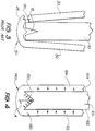
- FIG. 4 shows cathode mother plate 100 with a V-groove 150 formed along its lower end edge.
- the arc of groove 150 shown in Figure 4 is 90 degrees, however, as will be appreciated from the foregoing it is not essential that the groove by V-shaped or that the arc of the groove equal 90 degrees.
- V-groove 150 The shape and size of V-groove 150 is designed to perform several functions. Its primary function is to permit separation of the deposited metal envelope 120 from the mother plate 100 into two substantially equivalent sheets 122 and 124.
- the mother plate 100 when the mother plate 100 is placed in an electrolytic cell for, say, electro-refining of copper, it is interspersed between copper anodes and substantially immersed in an electrolytic solution.
- the copper from the anodes enters the electrolyte for redepositing on the cathode.
- the cathode remains in the electrolyte bath for between 5 and 14 days.
- the copper crystals When the copper crystals are deposited on the metal cathode, they are deposited at substantially right angles to the deposition surface. This is shown by arrows in Figure 4 .
- the copper will take the path of least resistance and endeavour to deposit on the cathode as quickly as possible. Accordingly, it will be appreciated that it is easier for the copper to deposit on the exterior side surfaces 102, 104 of the cathode plate 100 rather than in the V-groove 150. It is important, however, that copper is deposited in the V-groove since when the copper envelope is removed from mother plate 100, by pulling on the opposite sides of the metal envelope as discussed above, fracture or crack initiation begins in the frangible region 140 at the lower end of the mother plate 100.
- V-groove 150 is shaped to allow deposition of copper in the V-groove adjacent the apex with the line of weakness extending between the arc of the V-groove 150.
- a V-groove with an arc of 90° ⁇ 15° allows growth of copper in the V-groove while providing a line of weakness as shown by dotted line A between the arc of the V-groove.
- the position of line of weakness A in the V-groove causes the splitting of the deposited metal into two substantially equivalent sheets to initiate along the line of weakness or fracture line in the frangible region 140.
- the groove 150 shown in Figure 4 can be compared with the V-groove shown in the Figures 5 and 6 .
- V-groove 60 a shallow V-groove 60 is shown.
- the shape of this V-groove 60 does not provide as great a resistance to deposition of copper as does groove 150 shown in Figure 4 . Accordingly, copper is deposited quite readily in V-groove 60. This is desirable.
- the applicants have found that due to the shape of groove 60, the length and hence effectiveness of the line of weakness is reduced. Thus a stronger bond is formed between the two sides of the metal envelope making it more difficult to split the metal envelope into two substantially equivalent sheets. Indeed, experimental trials have shown that several cycles of rotation or flapping in the stripping machine may be required to separate such sheets and in some cases they may split in a manner similar to that shown in Figure 3 .
- the groove 70 is narrower and deeper. This creates a greater resistance to deposition of copper ions that enter V-groove 150 of Figure 4 or V-groove 60 of Figure 5 . In some cases, copper will not deposit throughout V-groove 70 and particularly not near the apex of the V-groove. This causes a bridging 80 of metal across the V-groove. This bridging of metal across the V-groove avoids formation of the line of weakness in the arc of the V-groove.
- the bridge 80 can act to strongly bind the two sides of the metal envelope which, once again, may result in the deposited metal requiring several cycles of rotation or flapping to separate into two sheets which, most likely, will not be substantially equivalent in size.
- the V-groove can be sized and shaped to trap gaseous material which further acts to define a line of weakness in the arc of the groove.
Landscapes
- Chemical & Material Sciences (AREA)
- Engineering & Computer Science (AREA)
- Chemical Kinetics & Catalysis (AREA)
- Electrochemistry (AREA)
- Materials Engineering (AREA)
- Metallurgy (AREA)
- Organic Chemistry (AREA)
- Electrolytic Production Of Metals (AREA)
Description
- The present invention relates to a cathode plate for use in electro-deposition of metal.
- There are various processes and apparatus for electro-refining or electro-winning metal.
- One particularly successful process for electro-depositing of copper for example is the so-called ISA PROCESS in which copper is deposited on a stainless steel cathode mother plate. The electrolytically deposited copper is then stripped from the cathode by first flexing the cathode to cause at least a part of the copper deposit to separate from the cathode and then wedge stripping or gas blasting the remainder of the copper from the cathode.
- In the ISA PROCESS the bottom edge of the cathode mother plate is generally covered with a release compound such as wax or a plastic edge strip to prevent deposition of copper thereon. This allows for removal of the electro-deposited copper as substantially equivalent separate sheets from both sides of the cathode plate. Such waxing of the cathode sheet, however, is time consuming and there is added cost both for applying the wax and for recovering the wax from the stripping process and associated housekeeping.
- To avoid these difficulties, some electro-refining/electro-winning operations use a so-called enveloped cathode process. In such a process the lower edge of the cathode sheet is not waxed and the electro-deposited metal is allowed to grow on both sides of the sheet and around the bottom edge of the cathode mother plate.
- Removal of the electrolytically deposited envelope of metal is then accomplished by flexing the cathode and pulling back the metal from both sides of the sheet so that it forms a V. The cathode mother plate is then removed from between the electrolytically deposited envelope of metal, the envelope is then closed and rotated from its vertical position to a horizontal position and transported to a stacking/bundling station.
- Not only does such a removal process require complex apparatus for opening the metal envelope, removing the cathode mother plate prior to closing of the envelope and rotating the envelope from the vertical to the horizontal position for stacking, such an arrangement is time consuming and generally not as quick as the ISA PROCESS stripping step.
- In conjunction with other parties, the applicant has recently developed a new process in which an envelope of metal is formed on the stainless steel cathode mother plate and then stripped into two separate sheets. This process is subject of co-pending International Patent Application No.
PCT/FI99/00979 figures 1A-1D and2A-2D attached herewith. - The initial step in stripping an electrolytically deposited metal envelope from its cathode mother sheet is to at least partially separate either side of the deposited envelope from the cathode sheet. In this regard reference is made to
figures 1A-1D . The enveloped cathode comprisescathode sheets cathode mother sheet 10 and joined along the lower edge thereof by afrangible portion 40. The cathode mother sheet is firstly flexed to provide separation of at least theupper end portion 50 of thesheets - The partially separated envelope as shown if
figure 1D is then subjected to a stripping operation as shown infigures 2A and 2B . The partially separatedsheets conveyor belt 50. The apparatus includes a wedge stripper orair blaster 130. Thesewedge strippers 130 enter the gap betweensheets cathode mother sheet 10. Thewedge strippers 130 release thesheets cathode mother sheet 10. Thesheets frangible portion 40 extending along the bottom edge of thecathode sheet 10 as shown inFigure 2B . To effect full separation of the electro-deposited metal envelope into separate substantially equivalent sheets. These sheets are 20 and 30 is held bygrippers frangible portion 40 from the substantial vertical position shown infigure 2B to the substantially horizontal position shown infigure 2C . This rotation separates the deposited metal into two substantially equivalent sheets. In many cases, a single rotation of thesheets sheets grippers sheet figure 2C , are adapted to pull the respective sheets slightly outward as shown infigure 2D . If the sheets, 20, 30 move outwardly in unison with the grippers, separation of thesheets frangible portion 40 has not in fact separated thesheets figure 2C ) of the sheets may be required. - If further manipulation/rotation of
sheets apparatus using grippers sheets - Once the
cathode sheets - In some cases it is quite difficult to separate the envelope of deposited metal into two separate sheets. As will be appreciated, repeated rotation or flapping of the sheet portions can be quite time consuming and reduces the overall efficiency of the process.
- Reference is made to
Figure 3 which shows agroove 15 in acathode mother plate 10 with deposited metal extending around the end of thecathode mother plate 10. Thisgroove 15 is formed in the bottom edge of the cathode mother plate as a 'growth effecting means' as described in co-pending International Patent Application No.PCT/FI99/00979 groove 15 the deposited metal may not cleanly release from the cathode plate or split into two substantiallyequivalent sheets Figure 3 , on occasion, the metal envelope separates into two sheets with alip 25 attached to one sheet. This lip extends around almost the entire end portion of themother plate 10. Thefracture line 35 betweenmetal sheets cathode mother plate 10 rather than being in the preferredfrangible region 40 at the lower end of the mother plate. - It is an object of the present invention to overcome or ameliorate at least one of the disadvantages of the prior art, or to provide a useful alternative to the prior art.
- In a first aspect, the present invention provides a method of electro-depositing an envelope of metal on a cathode said envelope including deposited metal on either side of said cathode and joined along at least one edge by a frangible portion, and being removable from said cathode by rotation of respective sides of the deposited metal envelope about the frangible portion to separate the deposited metal from the cathode into two substantially equivalent sheets,
the method comprising providing a groove on said cathode plate whereby metal deposited on and adjacent to said groove forms said frangible portion,
and wherein said groove is shaped such that a line of weakness is formed in the metal deposited within the groove such that separation of the two sheets of the deposited metal is initiated along said line of weakness, said groove is shaped as a V, with the line of weakness being formed within the arc of the V, the arc of the V-groove is between 75 and 105 degrees and most preferably the arc of the V-groove is substantially 90 degrees, and the deposited metal fills the entire groove, i.e. the groove is shaped to allow deposition of metal directly adjacent the apex of the groove. - The present applicant has determined that the size and shape of the groove in the cathode mother plate has an impact on the ability to separate the deposited metal envelope from the cathode into two substantially equivalent sheets.
- By appropriate sizing and shaping of the groove, it is possible to reliably provide a line of weakness between the two sides of the electro-deposited envelope, such that the separation or splitting of two separate sides of sheets of the deposited metal envelope is initiated on the line of weakness within the groove.
- If the line of weakness is not formed within the groove, the fracture line may be initiated outside the confines of the groove and in some cases may continue to propagate round the end of the plate to an exterior side of the cathode mother plate metal envelope as shown in
Figure 3 . The sheets may then fracture at a point outside the frangible region. Having such a line of fracture outside the frangible region creates difficulties in the stripping process. Firstly, it can render splitting of the two sheets quite difficult. In some instances it may be necessary to rotate or flap the sheets several times to provide separation. Clearly this is undesirable, and increases the residence time of the plate in the stripping machine and thereby slows production. - Further, having a line of fracture outside the frangible region will produce two sheets which are not substantially symmetrical or equivalent in size. One sheet may be essentially flat with another sheet having a small lip or hooked edge as shown in
Figure 3 . The resulting sheets with uneven edges are unsightly and difficult to handle particularly in high speed automated machinery. - The applicant has found that the size and shape of the groove can be tailored so that the line of weakness extending between the two sheets remains within the confines of the groove. The shape of the groove is a balance between allowing growth of the deposited metal in the groove while still permitting easy separation of the two sheets.
- In another aspect, the present invention provides a cathode plate for electro-deposition of metal according to claim 5.
- Unless the context clearly requires otherwise, throughout the description and the claims, the words 'comprise', 'comprising', and the like are to be construed in an inclusive sense as opposed to an exclusive or exhaustive sense; that is to say, in the sense of "including, but not limited to".
- The present invention will now be described by way of example only with reference to the accompanying drawings in which:
-
Figures 1A-2D are end elevational views of the process for stripping electro-deposited metal envelopes as developed by the applicant and are included for clarification purposes only. -
Figure 3 is an end elevational view of a cathode mother plate with a deposited metal envelope partially stripped into two separate sheets, -
Figure 4 is an end elevational view of an embodiment of the present invention, -
Figures 5 and 6 are end elevational views showing different shaped bottom edges of cathode plates. -
Figures 1A-2D andFigure 3 all relates to prior art mechanisms and are discussed above. - The applicants have found that it is possible to tailor a groove in the lower end of the mother plate such that a line of weakness is formed in the groove to thereby permit reliable fracture of the deposited metal envelope into two substantially equivalent and preferably symmetrical sheets.
- Reference is made to
Figure 4 which showscathode mother plate 100 with a V-groove 150 formed along its lower end edge. For the sake of simplicity, the arc ofgroove 150 shown inFigure 4 is 90 degrees, however, as will be appreciated from the foregoing it is not essential that the groove by V-shaped or that the arc of the groove equal 90 degrees. - The shape and size of V-
groove 150 is designed to perform several functions. Its primary function is to permit separation of the depositedmetal envelope 120 from themother plate 100 into two substantiallyequivalent sheets - How the V-groove provides this function will now be explained. As will be clear to persons skilled in the art, when the
mother plate 100 is placed in an electrolytic cell for, say, electro-refining of copper, it is interspersed between copper anodes and substantially immersed in an electrolytic solution. The copper from the anodes enters the electrolyte for redepositing on the cathode. Generally, to provide a "full term" deposit the cathode remains in the electrolyte bath for between 5 and 14 days. - When the copper crystals are deposited on the metal cathode, they are deposited at substantially right angles to the deposition surface. This is shown by arrows in
Figure 4 . Generally, the copper will take the path of least resistance and endeavour to deposit on the cathode as quickly as possible. Accordingly, it will be appreciated that it is easier for the copper to deposit on the exterior side surfaces 102, 104 of thecathode plate 100 rather than in the V-groove 150. It is important, however, that copper is deposited in the V-groove since when the copper envelope is removed frommother plate 100, by pulling on the opposite sides of the metal envelope as discussed above, fracture or crack initiation begins in thefrangible region 140 at the lower end of themother plate 100. It is desirable that this crack initiation begins at the apex of V-groove 150. Accordingly, it is preferable that V-groove 150 is shaped to allow deposition of copper in the V-groove adjacent the apex with the line of weakness extending between the arc of the V-groove 150. - The applicants have found that certain groove sizes and shapes permit such 'symmetrical' splitting of the deposited metal while others do not. A V-groove with an arc of 90°±15° allows growth of copper in the V-groove while providing a line of weakness as shown by dotted line A between the arc of the V-groove. When the deposited metal envelope is then removed, the position of line of weakness A in the V-groove causes the splitting of the deposited metal into two substantially equivalent sheets to initiate along the line of weakness or fracture line in the
frangible region 140. - The
groove 150 shown inFigure 4 can be compared with the V-groove shown in theFigures 5 and 6 . - In
Figure 5 , a shallow V-groove 60 is shown. The shape of this V-groove 60 does not provide as great a resistance to deposition of copper as does groove 150 shown inFigure 4 . Accordingly, copper is deposited quite readily in V-groove 60. This is desirable. However. the applicants have found that due to the shape ofgroove 60, the length and hence effectiveness of the line of weakness is reduced. Thus a stronger bond is formed between the two sides of the metal envelope making it more difficult to split the metal envelope into two substantially equivalent sheets. Indeed, experimental trials have shown that several cycles of rotation or flapping in the stripping machine may be required to separate such sheets and in some cases they may split in a manner similar to that shown inFigure 3 . - In
Figure 6 , thegroove 70 is narrower and deeper. This creates a greater resistance to deposition of copper ions that enter V-groove 150 ofFigure 4 or V-groove 60 ofFigure 5 . In some cases, copper will not deposit throughout V-groove 70 and particularly not near the apex of the V-groove. This causes a bridging 80 of metal across the V-groove. This bridging of metal across the V-groove avoids formation of the line of weakness in the arc of the V-groove. Thebridge 80 can act to strongly bind the two sides of the metal envelope which, once again, may result in the deposited metal requiring several cycles of rotation or flapping to separate into two sheets which, most likely, will not be substantially equivalent in size. - In another embodiment of the present invention, which is particularly suitable for electro winning processes, the V-groove can be sized and shaped to trap gaseous material which further acts to define a line of weakness in the arc of the groove.
Claims (6)
- A method of electro-depositing an envelope of metal on a cathode said envelope including deposited metal on either side of said cathode joined along at least one edge by a frangible portion, and being removable from said cathode by rotation of respective sides of the deposited metal envelope about the frangible portion to separate the deposited metal from the cathode into two substantially equivalent sheets,
the method comprising providing a groove on said cathode plate whereby metal deposited on and adjacent to said groove forms said frangible portion, wherein said groove is shaped such that a line of weakness is formed in the metal deposited within the groove and separation of the two sheets of deposited metal is initiated along said line of weakness,
wherein the groove is shaped as a V, the sides of the groove being between 75 and 105° apart, the line of weakness being formed and remaining within the arc of the V, and
wherein the deposited metal fills the entire groove. - A method as claimed in claim 1 wherein the sides of the groove are 90° apart.
- A method as claimed in any of the preceding claims wherein the groove is shaped to capture gas rising from below the cathode plate during deposition of metal.
- A cathode plate for electro-deposition of an envelope of metal, said cathode plate having a groove along at least one edge and shaped such that, in use, a line of weakness is formed in the metal deposited within the groove, whereby during stripping of metal from said cathode, separation of the envelope of metal into two substantially equivalent sheets is initiated along said line of weakness,
wherein the groove is shaped as a V, the sides of the groove being between 75 and 105° apart, the line of weakness being formed and remaining within the arc of the V, and
wherein the groove permits the deposited metal to fill the entire groove. - A cathode plate as claimed in claim 4 wherein the sides of the groove are 90° apart.
- A cathode plate as claimed in any one of claims 4 or 5 wherein the groove is shaped to capture gas rising from below the cathode plate during deposition of metal.
Applications Claiming Priority (3)
| Application Number | Priority Date | Filing Date | Title |
|---|---|---|---|
| AUPQ1066A AUPQ106699A0 (en) | 1999-06-18 | 1999-06-18 | Cathode plate |
| AUPQ106699 | 1999-06-18 | ||
| PCT/AU2000/000669 WO2000079028A1 (en) | 1999-06-18 | 2000-06-16 | Cathode plate |
Publications (3)
| Publication Number | Publication Date |
|---|---|
| EP1230440A1 EP1230440A1 (en) | 2002-08-14 |
| EP1230440A4 EP1230440A4 (en) | 2005-06-01 |
| EP1230440B1 true EP1230440B1 (en) | 2017-03-22 |
Family
ID=3815257
Family Applications (1)
| Application Number | Title | Priority Date | Filing Date |
|---|---|---|---|
| EP00936537.0A Expired - Lifetime EP1230440B1 (en) | 1999-06-18 | 2000-06-16 | Cathode plate |
Country Status (17)
| Country | Link |
|---|---|
| EP (1) | EP1230440B1 (en) |
| JP (1) | JP2003502512A (en) |
| CN (1) | CN1263897C (en) |
| AR (1) | AR024402A1 (en) |
| AU (1) | AUPQ106699A0 (en) |
| BR (1) | BR0011752A (en) |
| CA (1) | CA2377364C (en) |
| ES (1) | ES2627807T3 (en) |
| MX (1) | MXPA01013036A (en) |
| OA (1) | OA11970A (en) |
| PE (1) | PE20010502A1 (en) |
| PL (1) | PL201085B1 (en) |
| RO (1) | RO121039B1 (en) |
| RU (1) | RU2247799C2 (en) |
| TR (1) | TR200103610T2 (en) |
| WO (1) | WO2000079028A1 (en) |
| ZA (1) | ZA200110359B (en) |
Families Citing this family (7)
| Publication number | Priority date | Publication date | Assignee | Title |
|---|---|---|---|---|
| FI115727B (en) * | 2003-12-01 | 2005-06-30 | Outokumpu Oy | Devices and methods for loosening of deposits that have occurred during electrolytic purification |
| JP4640637B2 (en) * | 2005-03-28 | 2011-03-02 | Jx日鉱日石金属株式会社 | Management method of cathode plate V groove |
| DE102007000553A1 (en) | 2007-10-22 | 2009-04-23 | Wacker Chemie Ag | Fluoropolymer-silicone composites and methods of preparation |
| JP5103635B2 (en) * | 2008-03-10 | 2012-12-19 | 三井金属エンジニアリング株式会社 | Deposited metal plate peeling apparatus and peeling method |
| FI121238B (en) * | 2008-10-01 | 2010-08-31 | Outotec Oyj | Permanent cathode |
| JP2013040366A (en) * | 2011-08-12 | 2013-02-28 | Mesco Inc | Apparatus for stripping off electrodeposited metal and method for stripping off electrodeposited metal |
| CN104674299B (en) * | 2015-03-25 | 2016-11-09 | 大冶有色金属有限责任公司 | The recovery method of a small amount of fine copper of corrosion resistant plate attachment in copper electrolyzing refining |
Citations (1)
| Publication number | Priority date | Publication date | Assignee | Title |
|---|---|---|---|---|
| JPS534717A (en) * | 1976-05-20 | 1978-01-17 | Sumitomo Metal Mining Co | Master plate for electrodeposition of metals |
Family Cites Families (8)
| Publication number | Priority date | Publication date | Assignee | Title |
|---|---|---|---|---|
| GB1427348A (en) * | 1972-08-14 | 1976-03-10 | Imp Metal Ind Kynoch Ltd | Method of removing an electrodeposited metal from a cathod3 |
| GB1366987A (en) * | 1972-10-11 | 1974-09-18 | Gen Electric Co Ltd | Filament mount structures for use in electric incandescent filament lamps |
| DD140624A3 (en) * | 1976-02-26 | 1980-03-19 | Dietmar Schab | MUTTER PLATE WITH EDGE AND FLAKE INSULATION FOR THE PRODUCTION OF STARTER SHEETS |
| FI76382C (en) * | 1986-10-03 | 1988-10-10 | Outokumpu Oy | FARING EQUIPMENT FOR ORGANIZATION OF ELECTRICAL ELECTRICAL EQUIPMENT UTFAELLNING. |
| GB2196989B (en) * | 1986-11-04 | 1990-07-04 | Mim Techn Marketing Ltd | A method of stripping electrolytically deposited copper from a cathode |
| RU2020193C1 (en) * | 1991-12-29 | 1994-09-30 | Геннадий Иванович Алексеев | Method for separation of electrolytic deposits from cathodes |
| JPH09228090A (en) * | 1996-02-21 | 1997-09-02 | Nikko Kinzoku Kk | Cathode plate for wet electrolytic extraction of electrolytic refining |
| FI982569A7 (en) * | 1998-11-27 | 2000-05-28 | Outokumpu Oy | Device for separating metal precipitate from cathode |
-
1999
- 1999-06-18 AU AUPQ1066A patent/AUPQ106699A0/en not_active Abandoned
-
2000
- 2000-06-16 TR TR2001/03610T patent/TR200103610T2/en unknown
- 2000-06-16 MX MXPA01013036A patent/MXPA01013036A/en active IP Right Grant
- 2000-06-16 PL PL352310A patent/PL201085B1/en unknown
- 2000-06-16 RU RU2002100814/02A patent/RU2247799C2/en active
- 2000-06-16 EP EP00936537.0A patent/EP1230440B1/en not_active Expired - Lifetime
- 2000-06-16 PE PE2000000597A patent/PE20010502A1/en not_active IP Right Cessation
- 2000-06-16 WO PCT/AU2000/000669 patent/WO2000079028A1/en not_active Ceased
- 2000-06-16 BR BR0011752-8A patent/BR0011752A/en not_active Application Discontinuation
- 2000-06-16 AR ARP000103038A patent/AR024402A1/en active IP Right Grant
- 2000-06-16 RO ROA200101366A patent/RO121039B1/en unknown
- 2000-06-16 JP JP2001505369A patent/JP2003502512A/en active Pending
- 2000-06-16 OA OA1200100335A patent/OA11970A/en unknown
- 2000-06-16 CN CNB008091366A patent/CN1263897C/en not_active Expired - Fee Related
- 2000-06-16 CA CA002377364A patent/CA2377364C/en not_active Expired - Lifetime
- 2000-06-16 ES ES00936537.0T patent/ES2627807T3/en not_active Expired - Lifetime
-
2001
- 2001-12-18 ZA ZA200110359A patent/ZA200110359B/en unknown
Patent Citations (1)
| Publication number | Priority date | Publication date | Assignee | Title |
|---|---|---|---|---|
| JPS534717A (en) * | 1976-05-20 | 1978-01-17 | Sumitomo Metal Mining Co | Master plate for electrodeposition of metals |
Also Published As
| Publication number | Publication date |
|---|---|
| AR024402A1 (en) | 2002-10-02 |
| PE20010502A1 (en) | 2001-04-27 |
| TR200103610T2 (en) | 2002-05-21 |
| JP2003502512A (en) | 2003-01-21 |
| BR0011752A (en) | 2002-04-02 |
| RU2247799C2 (en) | 2005-03-10 |
| EP1230440A1 (en) | 2002-08-14 |
| PL352310A1 (en) | 2003-08-11 |
| CA2377364C (en) | 2008-10-28 |
| MXPA01013036A (en) | 2003-08-20 |
| WO2000079028A1 (en) | 2000-12-28 |
| EP1230440A4 (en) | 2005-06-01 |
| CA2377364A1 (en) | 2000-12-28 |
| CN1357059A (en) | 2002-07-03 |
| OA11970A (en) | 2006-04-17 |
| AUPQ106699A0 (en) | 1999-07-08 |
| CN1263897C (en) | 2006-07-12 |
| ZA200110359B (en) | 2002-12-18 |
| ES2627807T3 (en) | 2017-07-31 |
| PL201085B1 (en) | 2009-03-31 |
| RO121039B1 (en) | 2006-11-30 |
Similar Documents
| Publication | Publication Date | Title |
|---|---|---|
| CN102362011B (en) | Equipment for stripping metal from cathode plates | |
| CA2377364C (en) | Cathode plate | |
| CN102084036A (en) | Stripping apparatus and method for removing an electrodeposited metal layer from a cathode plate | |
| US4840710A (en) | Method of stripping electrolytically deposited copper from a cathode | |
| AU768314B2 (en) | Cathode plate | |
| AU768007B2 (en) | Device for separating metal deposit from a cathode | |
| US6814847B1 (en) | Method and apparatus for electro-deposition of metal | |
| US3530047A (en) | Stripping of sheet metal electrodeposits from starting sheet blanks | |
| JP5565337B2 (en) | Electrodeposition metal stripping device | |
| AU776012B2 (en) | Method and apparatus for electro-deposition of metal | |
| WO2014019070A1 (en) | Method and apparatus for starter sheet stripping | |
| ZA200508974B (en) | Cathode plate | |
| US7964080B2 (en) | Device and method for handling metal sheets | |
| AU2008286233B2 (en) | Apparatus for stripping metal from a cathode plate | |
| GB2196989A (en) | Stripping electrolytically deposited copper | |
| US3950232A (en) | Process for removing electrodeposits | |
| TH42893A (en) | Cathode Island Separation Device | |
| AU2004234421A1 (en) | Cathode plate |
Legal Events
| Date | Code | Title | Description |
|---|---|---|---|
| PUAI | Public reference made under article 153(3) epc to a published international application that has entered the european phase |
Free format text: ORIGINAL CODE: 0009012 |
|
| 17P | Request for examination filed |
Effective date: 20011227 |
|
| AK | Designated contracting states |
Kind code of ref document: A1 Designated state(s): AT BE CH CY DE DK ES FI FR GB GR IE IT LI LU MC NL PT SE |
|
| AX | Request for extension of the european patent |
Free format text: AL;LT;LV;MK;RO;SI |
|
| RBV | Designated contracting states (corrected) |
Designated state(s): AT BE DE ES FI SE |
|
| A4 | Supplementary search report drawn up and despatched |
Effective date: 20050420 |
|
| 17Q | First examination report despatched |
Effective date: 20070716 |
|
| GRAP | Despatch of communication of intention to grant a patent |
Free format text: ORIGINAL CODE: EPIDOSNIGR1 |
|
| INTG | Intention to grant announced |
Effective date: 20160901 |
|
| GRAJ | Information related to disapproval of communication of intention to grant by the applicant or resumption of examination proceedings by the epo deleted |
Free format text: ORIGINAL CODE: EPIDOSDIGR1 |
|
| GRAR | Information related to intention to grant a patent recorded |
Free format text: ORIGINAL CODE: EPIDOSNIGR71 |
|
| GRAS | Grant fee paid |
Free format text: ORIGINAL CODE: EPIDOSNIGR3 |
|
| GRAA | (expected) grant |
Free format text: ORIGINAL CODE: 0009210 |
|
| INTC | Intention to grant announced (deleted) | ||
| INTG | Intention to grant announced |
Effective date: 20170208 |
|
| AK | Designated contracting states |
Kind code of ref document: B1 Designated state(s): AT BE DE ES FI SE |
|
| REG | Reference to a national code |
Ref country code: AT Ref legal event code: REF Ref document number: 877871 Country of ref document: AT Kind code of ref document: T Effective date: 20170415 |
|
| REG | Reference to a national code |
Ref country code: DE Ref legal event code: R096 Ref document number: 60049583 Country of ref document: DE |
|
| REG | Reference to a national code |
Ref country code: SE Ref legal event code: TRGR |
|
| REG | Reference to a national code |
Ref country code: ES Ref legal event code: FG2A Ref document number: 2627807 Country of ref document: ES Kind code of ref document: T3 Effective date: 20170731 |
|
| REG | Reference to a national code |
Ref country code: DE Ref legal event code: R097 Ref document number: 60049583 Country of ref document: DE |
|
| PLBE | No opposition filed within time limit |
Free format text: ORIGINAL CODE: 0009261 |
|
| STAA | Information on the status of an ep patent application or granted ep patent |
Free format text: STATUS: NO OPPOSITION FILED WITHIN TIME LIMIT |
|
| 26N | No opposition filed |
Effective date: 20180102 |
|
| PGFP | Annual fee paid to national office [announced via postgrant information from national office to epo] |
Ref country code: FI Payment date: 20190620 Year of fee payment: 20 |
|
| PGFP | Annual fee paid to national office [announced via postgrant information from national office to epo] |
Ref country code: SE Payment date: 20190516 Year of fee payment: 20 Ref country code: BE Payment date: 20190625 Year of fee payment: 20 |
|
| PGFP | Annual fee paid to national office [announced via postgrant information from national office to epo] |
Ref country code: AT Payment date: 20190626 Year of fee payment: 20 Ref country code: DE Payment date: 20190628 Year of fee payment: 20 Ref country code: ES Payment date: 20190725 Year of fee payment: 20 |
|
| REG | Reference to a national code |
Ref country code: AT Ref legal event code: UEP Ref document number: 877871 Country of ref document: AT Kind code of ref document: T Effective date: 20170322 |
|
| REG | Reference to a national code |
Ref country code: DE Ref legal event code: R071 Ref document number: 60049583 Country of ref document: DE |
|
| REG | Reference to a national code |
Ref country code: FI Ref legal event code: MAE |
|
| REG | Reference to a national code |
Ref country code: SE Ref legal event code: EUG |
|
| REG | Reference to a national code |
Ref country code: AT Ref legal event code: MK07 Ref document number: 877871 Country of ref document: AT Kind code of ref document: T Effective date: 20200616 |
|
| REG | Reference to a national code |
Ref country code: BE Ref legal event code: MK Effective date: 20200616 |
|
| REG | Reference to a national code |
Ref country code: ES Ref legal event code: FD2A Effective date: 20200929 |
|
| PG25 | Lapsed in a contracting state [announced via postgrant information from national office to epo] |
Ref country code: ES Free format text: LAPSE BECAUSE OF EXPIRATION OF PROTECTION Effective date: 20200617 |