EP1229776A2 - Axial fan motor and cooling unit - Google Patents
Axial fan motor and cooling unit Download PDFInfo
- Publication number
- EP1229776A2 EP1229776A2 EP02000614A EP02000614A EP1229776A2 EP 1229776 A2 EP1229776 A2 EP 1229776A2 EP 02000614 A EP02000614 A EP 02000614A EP 02000614 A EP02000614 A EP 02000614A EP 1229776 A2 EP1229776 A2 EP 1229776A2
- Authority
- EP
- European Patent Office
- Prior art keywords
- fan motor
- axial fan
- metal plates
- type
- casing
- Prior art date
- Legal status (The legal status is an assumption and is not a legal conclusion. Google has not performed a legal analysis and makes no representation as to the accuracy of the status listed.)
- Granted
Links
Images








Classifications
-
- H—ELECTRICITY
- H05—ELECTRIC TECHNIQUES NOT OTHERWISE PROVIDED FOR
- H05K—PRINTED CIRCUITS; CASINGS OR CONSTRUCTIONAL DETAILS OF ELECTRIC APPARATUS; MANUFACTURE OF ASSEMBLAGES OF ELECTRICAL COMPONENTS
- H05K7/00—Constructional details common to different types of electric apparatus
- H05K7/20—Modifications to facilitate cooling, ventilating, or heating
- H05K7/20009—Modifications to facilitate cooling, ventilating, or heating using a gaseous coolant in electronic enclosures
- H05K7/20136—Forced ventilation, e.g. by fans
- H05K7/20172—Fan mounting or fan specifications
-
- F—MECHANICAL ENGINEERING; LIGHTING; HEATING; WEAPONS; BLASTING
- F04—POSITIVE - DISPLACEMENT MACHINES FOR LIQUIDS; PUMPS FOR LIQUIDS OR ELASTIC FLUIDS
- F04D—NON-POSITIVE-DISPLACEMENT PUMPS
- F04D25/00—Pumping installations or systems
- F04D25/02—Units comprising pumps and their driving means
- F04D25/06—Units comprising pumps and their driving means the pump being electrically driven
- F04D25/0606—Units comprising pumps and their driving means the pump being electrically driven the electric motor being specially adapted for integration in the pump
- F04D25/0613—Units comprising pumps and their driving means the pump being electrically driven the electric motor being specially adapted for integration in the pump the electric motor being of the inside-out type, i.e. the rotor is arranged radially outside a central stator
-
- F—MECHANICAL ENGINEERING; LIGHTING; HEATING; WEAPONS; BLASTING
- F04—POSITIVE - DISPLACEMENT MACHINES FOR LIQUIDS; PUMPS FOR LIQUIDS OR ELASTIC FLUIDS
- F04D—NON-POSITIVE-DISPLACEMENT PUMPS
- F04D29/00—Details, component parts, or accessories
- F04D29/58—Cooling; Heating; Diminishing heat transfer
- F04D29/582—Cooling; Heating; Diminishing heat transfer specially adapted for elastic fluid pumps
-
- F—MECHANICAL ENGINEERING; LIGHTING; HEATING; WEAPONS; BLASTING
- F04—POSITIVE - DISPLACEMENT MACHINES FOR LIQUIDS; PUMPS FOR LIQUIDS OR ELASTIC FLUIDS
- F04D—NON-POSITIVE-DISPLACEMENT PUMPS
- F04D29/00—Details, component parts, or accessories
- F04D29/60—Mounting; Assembling; Disassembling
- F04D29/601—Mounting; Assembling; Disassembling specially adapted for elastic fluid pumps
-
- H—ELECTRICITY
- H02—GENERATION; CONVERSION OR DISTRIBUTION OF ELECTRIC POWER
- H02K—DYNAMO-ELECTRIC MACHINES
- H02K5/00—Casings; Enclosures; Supports
- H02K5/04—Casings or enclosures characterised by the shape, form or construction thereof
-
- H—ELECTRICITY
- H02—GENERATION; CONVERSION OR DISTRIBUTION OF ELECTRIC POWER
- H02K—DYNAMO-ELECTRIC MACHINES
- H02K5/00—Casings; Enclosures; Supports
- H02K5/04—Casings or enclosures characterised by the shape, form or construction thereof
- H02K5/18—Casings or enclosures characterised by the shape, form or construction thereof with ribs or fins for improving heat transfer
-
- H—ELECTRICITY
- H02—GENERATION; CONVERSION OR DISTRIBUTION OF ELECTRIC POWER
- H02K—DYNAMO-ELECTRIC MACHINES
- H02K7/00—Arrangements for handling mechanical energy structurally associated with dynamo-electric machines, e.g. structural association with mechanical driving motors or auxiliary dynamo-electric machines
- H02K7/08—Structural association with bearings
- H02K7/085—Structural association with bearings radially supporting the rotary shaft at only one end of the rotor
-
- H—ELECTRICITY
- H02—GENERATION; CONVERSION OR DISTRIBUTION OF ELECTRIC POWER
- H02K—DYNAMO-ELECTRIC MACHINES
- H02K7/00—Arrangements for handling mechanical energy structurally associated with dynamo-electric machines, e.g. structural association with mechanical driving motors or auxiliary dynamo-electric machines
- H02K7/14—Structural association with mechanical loads, e.g. with hand-held machine tools or fans
Definitions
- the present invention relates to an axial fan motor, and more particularly, to an axial fan motor for use in a cooling unit for air-cooling the heat sink of a heating element, such as a CPU, as well as to a cooling unit equipped with the axial fan motor.
- a heat sink is generally used in electronic equipment, such as a personal computer, in order to effectively release heat from a heating element, such as a CPU.
- a heating element such as a CPU.
- an axial fan motor is used in order to forcibly cool the heat sink.
- an axial fan motor integrally equipped with air rectification blades is proposed in, for example, Japanese Application No. 2000-223696.
- the air rectification blades are intended to control air flow exhausted from the axial fan motor so as to produce uniform cooling air flow without whirls.
- An object of the present invention is to solve the above-mentioned problem in the conventional axial fan motor and to provide an axial fan motor capable of effectively and efficiently releasing heat from a heating element, such as a CPU, through application of a metallic material to a casing and air rectification blades, which are conventionally resin moldings, so as to utilize good heat conductivity of metal, to thereby facilitate compliance with demands for reduction in size, weight, and cost of electronic equipment, as well as to provide a cooling unit equipped with the axial fan motor.
- the present invention provides an axial fan motor for a cooling unit, adapted to air-cool a heat sink of a heating element, such as a CPU, and thermally connected to the heat sink, which axial fan motor comprises a casing formed of a plurality of laminated metal plates.
- Heat released from the heating element such as a CPU is conducted to the heat sink and is then carried away from the heat sink by means of cooling air which is caused to flow by the axial fan motor. Also, the heat is conducted through metal to the entire casing of the axial fan motor and is then carried away from the casing by means of the cooling air.
- the cooling efficiency of the heat sink is significantly enhanced. Therefore, the heat sink can assume a thin, flat form, thereby enabling a further reduction in size, weight, and cost of electronic equipment.
- the casing of the axial fan motor is composed of a plurality of laminated metal plates, it is sufficient to provide metal plates and connection means (such as caulking, riveting, or welding).
- connection means such as caulking, riveting, or welding.
- the method according to the present invention permits to manufacture a casing without the involvement of such machining processes, thereby facilitating manufacture and enhancing productivity. Since metal plates of various shapes can be caulked together, a wide range of combinations of metal plates for lamination are available.
- the plurality of metal plates comprise a single first metal plate A and a plurality of second metal plates B.
- the single first metal plate A which is an outermost layer located at the air exhaust side of a fan, comprises a peripheral portion having a circular inner edge; a central portion having a circular outer edge; and a plurality of arm portions for connecting the peripheral portion and the central portion.
- a bearing holder of a rotary shaft of the fan is attached to the central portion.
- the plurality of second metal plates B comprises, singly or in combination, the following metal plates B1, B2, and B3: (1) a metal plate B1 which includes only a peripheral portion having a circular inner edge; (2) a metal plate B2 which includes only a peripheral portion having a circular inner edge and assumes an outline of greater size than the outline of the metal plate B1; and (3) a metal plate B3 which includes only a peripheral portion having a circular inner edge and a single cutout portion formed in the peripheral portion and assumes an outline substantially equal in size to the outline of the metal plate B1.
- the bearing holder supports a rotary portion of the axial fan motor via a bearing, and a stationary portion (stator) of the axial fan motor is fixedly attached to the bearing holder, whereby the main body (the stationary portion and the rotary portion) of the axial fan motor is fixedly attached to the casing.
- the assembly of the axial fan motor is simplified.
- all of the plurality of second metal plates B are the metal plates B1. Since metal plates of merely a single kind; i.e., merely the metal plates B1, are used as the second metal plates B, manufacture of the casing is significantly facilitated.
- all of the plurality of second metal plates B are the metal plates B3. Since metal plates of merely a single kind; i.e., merely the metal plates B3, are used as the second metal plates B, manufacture of the casing is significantly facilitated. Since cooling air flows between the interior of the casing and the exterior of the casing through the cutout portions of the metal plates B3, the efficiency of releasing heat from the casing is further enhanced to thereby further enhance the cooling efficiency of the heat sink.
- the metal plates B3 are arranged such that the angular positions of the cutout portions of the metal plates B3 are successively shifted in the same circumferential direction and such that a phase shift of a predetermined angle is produced between two adjacent cutout portions. Since cooling air flows between the interior of the casing and the exterior of the casing through the cutout portions of the metal plates B3 which are circumferentially arranged at predetermined intervals, heat can be uniformly released from the casing to thereby lessen thermal stress in the casing. Thus, the durability of the casing can be enhanced.
- the plurality of second metal plates B comprise the metal plates B1 and B2 such that the metal plates B1 and B2 are laminated alternately. Since peripheral edge portions of the metal plates B2 which project beyond the peripheral edges of the metal plates B1 serve as fins, the efficiency of releasing heat from the casing is further enhanced to thereby further enhance the cooling efficiency of the heat sink.
- the plurality of second metal plates B comprise the metal plates B2 and B3 such that the metal plates B2 and B3 are laminated alternately. Since peripheral edge portions of the metal plates B2 which project beyond the peripheral edges of the metal plates B3 serve as fins, and cooling air flows between the interior of the casing and the exterior of the casing through the cutout portions of the metal plates B3, the efficiency of releasing heat from the casing is greatly enhanced to thereby greatly enhance the cooling efficiency of the heat sink.
- the metal plates B2 and B3 are arranged alternately such that the angular positions of the cutout portions of the metal plates B3 are successively shifted in the same circumferential direction and such that a phase shift of a predetermined angle is produced between two adjacent cutout portions. Since cooling air flows between the interior of the casing and the exterior of the casing through the cutout portions of the metal plates B3 which are circumferentially arranged at predetermined intervals, heat can be uniformly released from the casing to thereby lessen thermal stress in the casing. Thus, the durability of the casing can be enhanced.
- the first metal plate A and the bearing holder are integrally formed of the same metal.
- This structural feature simplifies assembly of the casing and the main body (the stationary portion and the rotary portion) of the axial fan motor to thereby further simplify the assembled structure of the axial fan motor. Since the bearing holder is made of metal, release of heat from a bearing portion is accelerated to thereby eliminate an adverse effect of heat on a bearing.
- the present invention further provides an axial fan motor for a cooling unit, adapted to air-cool a heat sink of a heating element, such as a CPU, and thermally connected to the heat sink, which axial fan motor comprises a casing formed of a plurality of metal plates and a single or a plurality of resin plates arranged in layers.
- the cooling efficiency of the heat sink drops slightly as compared with the casing formed of metal plates only.
- the weight and cost of the casing drop, to thereby enable a further reduction in weight and cost of electronic equipment.
- the casing can be manufactured from a plurality of metal plates, a single or a plurality of resin plates, and connection means, the following effect is yielded.
- the method according to the present invention permits to manufacture a casing without the involvement of such machining processes, thereby facilitating manufacture and enhancing productivity.
- the single or plurality of resin plates comprise at least a single resin plate C, which is an outermost layer located at an air exhaust side of a fan.
- the resin plate C comprises a peripheral portion having a circular inner edge; a central portion having a circular outer edge; and a plurality of arm portions for connecting the peripheral portion and the central portion.
- a bearing holder of a rotary shaft of the fan is attached to the central portion.
- the bearing holder supports a rotary portion of the axial fan motor via a bearing, and a stationary portion of the axial fan motor is fixedly attached to the bearing holder, whereby the main body (the stationary portion and the rotary portion) of the axial fan motor is attached to the casing. In this manner, the assembled structure of the axial fan motor is simplified.
- the resin plate C and the bearing holder are integrally formed of the same resin.
- This structural feature simplifies assembly of the casing and the main body (the stationary portion and the rotary portion) of the axial fan motor to thereby further simplify the assembled structure of the axial fan motor.
- the predetermined angle is 90 degrees. Every time four metal plates B3 are laminated, the cutout portions of the metal plates B3 are arranged all around the casing. Thus, heat can be further uniformly released from the casing to thereby further lessen thermal stress in the casing. Thus, the durability of the casing can further be enhanced.
- one of the arm portions has a window formed therein so as to allow looking therethrough at least at a terminal of a lead wire, and holder means for holding a lead wire.
- the lead wire terminal and a motor winding terminal can be connected while looking through the window.
- the connection work is facilitated; lead wires can be efficiently run; and the appearance of the product is improved.
- the axial fan motor further comprises an air rectification means.
- the air rectification means straightens cooling air which is caused to flow by the axial fan motor, whereby the cooling air can reach deep into the heat sink along its fins without involvement of whirls to thereby further enhance the cooling efficiency of the heat sink.
- the air rectification means is disposed between the axial fan motor and the heat sink and assumes the form of a air rectification cylinder equipped with a plurality of air rectification blades.
- a air rectification cylinder equipped with a plurality of air rectification blades is alleviated, thereby suppressing a phenomenon that an air flow rate at a central portion of the axial fan motor becomes lower than that at a peripheral portion of the axial fan motor.
- the cooling air can reach deep into the heat sink to thereby further uniformly cool the heat sink.
- the cooling efficiency of the heat sink can further be enhanced.
- the present invention still further provides a cooling unit comprising an axial fan motor of the present invention and a shroud for mounting the axial fan motor above a heat sink.
- the shroud comprises a support base having a central portion cut out and on which a casing of the axial fan motor is mounted; and a plurality of legs extending downward from a plurality of positions on a peripheral edge of the support base.
- the support base covers and is thermally connected to the heat sink, and end portions of the legs are engaged with a base of the heat sink, whereby the shroud is fixedly attached to the heat sink.
- the shroud and a plate serving as an outermost layer located at the air intake side of the fan of the axial fan motor and partially constituting the casing of the axial fan motor are integrally formed of the same material.
- the shroud and a single plate which is one of the layers constituting the casing of the axial fan motor and is an outermost layer located at the air intake side of the fan are integrally formed of the same material, the shroud and the casing can be readily assembled.
- the axial fan motor can be readily mounted above the heat sink.
- a cooling unit equipped with an axial fan motor according to the first embodiment of the present invention is used to cool a heating element, such as a CPU.
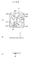
- the cooling unit 1 includes a heat sink 10 (FIG. 1C); an axial fan motor 30 (FIG. 1A) for air-cooling the heat sink 10; and a shroud 20 (FIG. 1B) serving as a stand for mounting the axial fan motor 30 above the heat sink 10.
- FIGS. 2 and 3 show the assembled cooling unit 1.
- the heat sink 10 includes a base 11, which is a square metal plate of good heat conductivity having a certain thickness, and fins 12 fixedly mounted on the base 11.
- a package (not shown) of a heating element, such as a CPU, is in contact with the side of the base 11 opposite the fin side. Heat is conducted from the package to the base 11 and then to the fins 12, from which the heat is released. In this manner, temperature rise within the package is suppressed to thereby ensure proper operation of the heating element.
- Engagement recesses 13 are formed on side walls of the square base 11 in the vicinity of four corners in order to receive engagement hooks 24 formed at ends of legs 22, which will be described later, of the shroud 20.
- the legs 22 extend downward outside the fins 12 of the heat sink 10.
- the shroud 20 includes a support base 21 and four legs 22, which extend downward from four corners of the support base 21.
- the support base 21 assumes a square shape similar to that of the base 11.
- the support base 21 has a mounting surface 25 on which a casing 60 (see FIGS. 8 and 9) of the axial fan motor 30 is mounted in a fixed condition.
- protrusions 23 are provided on the mounting surface 25 of the support base 21 of the shroud 20 in the vicinity of the corresponding four corners of the support base 21.
- the protrusions 23 are fitted into corresponding engagement holes 61, which will be described later, formed in the casing 60 in the vicinity of four corners, thereby fixedly mounting the axial fan motor 30 in place on the shroud 20.
- the casing 60 is thermally connected to the support base 21.
- the expression “thermally connected” means that two members are connected such that heat can be conducted therebetween.
- the engagement hooks 24 formed at the corresponding ends of the legs 22 of the shroud 20 are engaged with the corresponding engagement recesses 13 formed in the base 11, whereby the shroud 20 is fixedly attached to the heat sink 10 in such a manner as to cover the heat sink 10.
- the support base 21 of the shroud 20 abuts the tops of the fins 12 of the heat sink 10 to thereby establish thermal connection therebetween.
- Heat of the heat sink 10 is conducted to the shroud 20 and then to the casing 60.
- the shroud 20 is an integral product made of a metal of good thermal conductivity.
- the shroud 20 can be a resin molding.
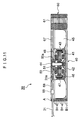
- the axial fan motor 30 includes a main body 40; the casing 60, which encloses the main body 40; and a bearing holder 50, which is located between the main body 40 and the casing 60 and is adapted to fixedly connect the main body 40 and the casing 60.
- the main body 40 includes a motor and rotary blades; i.e., a stationary portion 41 and a rotary portion (a rotor with blades) 42.
- the stationary portion 41 is configured in the following manner.
- a stator core is fitted to an end part of a cylindrical portion 50a of the bearing holder 50.
- the bearing holder 50 is fixedly connected to the casing 60.
- a PCB (Printed Circuit Board) 48 is located at an upper portion of the stationary portion 41 in such a manner as to be fitted to the cylindrical portion 50a of the bearing holder 50.
- terminals 31a of lead wires 31 and terminals of windings of the stationary portion 41, which serves as a stator of the motor, are soldered.
- the rotary portion 42 is configured in the following manner.
- a rotary shaft 44 stands at the center of the bottom of a bottomed rotary cylinder 43.
- the rotary shaft 44 is rotatably supported by the cylindrical portion 50a of the bearing holder 50 via a pair of ball bearings 51.
- Pairs each consisting of a permanent magnet 46 and a yoke 47 are circumferentially arranged at equal intervals along the inner circumferential wall of the bottomed rotary cylinder 43.
- the permanent magnets 46 and the yokes 47 arranged in pairs and the bottomed rotary cylinder 43 constitute a rotor of the motor.
- a number of blades 45 are attached to the outer circumferential wall of the bottomed rotary cylinder 43.
- the bottomed rotary cylinder 43 and the blades 45 are usually formed into a unitary body through resin molding.
- the bearing holder 50 is fixedly attached to the casing 60 such that a flange portion 50b extending from the upper base end of the cylindrical portion 50a is fixedly attached onto a central portion 63A of a first metal plate A, which will be described later, of the casing 60 by use of four screws 72. In this manner, the main body 40 (stationary portion 41 and rotary portion 42) is supported by and attached to the casing 60 to thereby form the axial fan motor 30.
- the bearing holder 50 is made of metal.
- the casing 60 is composed of a plurality of laminated metal plates.
- the plurality of metal plates include a single first metal plate A, which is the outermost layer located at the air exhaust side of a fan, and a plurality of remaining second metal plates B.
- fan denotes a structural feature of the axial fan motor 30 which serves as a fan (excluding motor-related structural features, such as the stationary portion 41, the permanent magnets 46, and the yokes 47).
- the first metal plate A includes a peripheral portion 62A having a circular inner edge 65A; a central portion 63A having a circular outer edge 66A; and a plurality of (4) arm portions 64A which connect the peripheral portion 62A and the central portion 63A.
- the metal plate A has four circular holes 61A formed in the vicinity of the corresponding four corners thereof.
- the circular holes 61A serve as the corresponding engagement holes 61 formed in the casing 60 in the vicinity of the corresponding four corners thereof.
- the peripheral portion 62A has an outline, as viewed from above, similar to those of the base 11 and the support base 21 of the shroud 20. As mentioned previously, the flange portion 50b of the bearing holder 50 is fixedly attached to the central portion 63A by use of the screws 72.
- the circular inner edge 65A of the peripheral portion 62A and the circular outer edge 66A of the central portion 63A define a fan exhaust port 67.
- a window 68 is formed through blanking in a single arm portion 64A so that the lead wires 31 and the terminals 31a can be seen therethrough.
- the window 68 extends to the peripheral portion 62A and extends to the central portion 63A such that the size thereof is expanded so as to facilitate soldering of the terminals 31a and terminals of motor windings.
- Holder means 69 for holding the lead wires 31 is provided at the substantially lengthwise center of the window 68.
- the holder means 69 is formed integral with the corresponding arm portion 64A in the process of forming the metal plate A through blanking, such that opposite ends project into the exhaust port 67. The opposite ends are bent so as to assume a substantially box-like form as shown in FIG. 4C.
- a plurality of second metal plates B each assume the form of a metal plate B1 shown in FIG. 5.
- the metal plate B1 has an outline equal in size to the outline of the first metal plate A and is merely composed of a peripheral portion 62B1 having a circular inner edge 65B1. That is, in contrast to the first metal plate A, the metal plate B1 does not have a central portion and arm portions for connecting the central portion and the peripheral portion 62B1.
- the metal plate B1 has four circular holes 61B1 formed in the vicinity of the corresponding four corners thereof.
- the circular holes 61B1 serve as the corresponding engagement holes 61 formed in the casing 60 in the vicinity of the corresponding four corners thereof.
- the first metal plate A and a plurality of second metal plates B1 are laminated such that the first metal plate A becomes the outermost layer located at the air exhaust side of the fan. Accordingly, the second metal plates B1 are arranged underneath the first metal plate A.
- the layered metal plates A and B1 are integrally laminated by caulking.
- Other methods for integrally laminating the metal plates A and B1 include the following: riveting by use of rivets inserted through corresponding rivet holes which are formed in the vicinity of the engagement holes 61 (circular holes 61A and 61B1); bolting; bonding; and peripheral welding.
- the axial fan motor 30 takes cooling air into the heat sink 10 from around the heat sink 10.
- the cooling air enters deep into the heat sink 10 to thereby take heat from the fins 12.
- the cooling air flows through a central hollow portion of the shroud 20 and the interior of the casing 60 and is then exhausted from the exhaust port 67.
- the shroud 20 is interposed between the axial fan motor 30 and the heat sink 10 to thereby establish a certain distance therebetween, there is suppressed an adverse effect of the main body 40 of the axial fan motor 30 on deep entry of cooling air into the heat sink 10.
- the cooling air Flowing through the central hollow portion of the shroud 20 and the interior of the casing 60, the cooling air also takes heat from the shroud 20 and the casing 60 to thereby effectively cool the heat sink 10 in two stages.
- the first embodiment which is configured and operates as mentioned above, yields the following effects.
- the axial fan motor 30, which is adapted to air-cool the heat sink 10 of a heating element, such as a CPU, and is thermally connected to the heat sink 10, includes the casing 60 which, in turn, includes a plurality of laminated metal plates.
- heat released from the heating element, such as a CPU is conducted to the heat sink 10 and is then carried away from the heat sink 10 by means of cooling air which is caused to flow by the axial fan motor 30.
- the heat is conducted through the shroud 20 made of a metal to the entire casing 60 of the axial fan motor 30 and is then carried away from the casing 60 by means of the cooling air which is caused to flow by the axial fan motor 30.
- the cooling efficiency of the heat sink 10 is significantly enhanced. Therefore, the heat sink 10 can assume a thin, flat form, thereby enabling a further reduction in size, weight, and cost of electronic equipment.
- the casing 60 of the axial fan motor 30 is composed of a plurality of laminated metal plates
- the casing 60 can be manufactured by use of the metal plates and connection means (such as caulking, riveting, or welding).
- connection means such as caulking, riveting, or welding
- the casing 60 can be manufactured without the involvement of such machining processes, thereby facilitating manufacture and enhancing productivity.
- the plurality of metal plates is composed of a single first metal plate A and a plurality of second metal plates B.
- the single first metal plate A which is the outermost layer located at the air exhaust side of a fan, includes the peripheral portion 62A having the circular inner edge 65A; the central portion 63A having the circular outer edge 66A; and a plurality of arm portions 64A for connecting the peripheral portion 62A and the central portion 63A.
- the bearing holder 50 of the rotary shaft 44 of the fan i.e., the rotary shaft 44 of the axial fan motor 30
- All of the plurality of second metal plates B are the metal plates B1, each of which is composed of the peripheral portion 62B1 having the circular inner edge 65B1.
- the bearing holder 50 supports the rotary portion (the rotor with blades) 42 of the axial fan motor 30 via a bearing, and the stationary portion 41 of the axial fan motor 30 is fixedly attached to the bearing holder 50, whereby the main body 40 (the stationary portion 41 and the rotary portion 42) of the axial fan motor 30 is attached to the casing 60.
- the assembled structure of the axial fan motor 30 is simplified. Since metal plates of merely a single kind; i.e., merely the metal plates B1, are used as the second metal plates B, manufacture of the casing 60 is significantly facilitated.
- One of the arm portions 64A has the window 68 formed therein to allow looking therethrough at least at the terminals 31a of the lead wires 31, and the holder means 69 for holding the lead wires 31.
- the lead wire terminals 31a and corresponding motor winding terminals can be connected while looking through the window 68.
- the connection work is facilitated; the lead wires 31 can be efficiently run; and the appearance of the product is improved.
- the bearing holder 50 is made of metal, release of heat from the bearing portion of the rotary portion 42 of the axial fan motor 30 is accelerated to thereby eliminate an adverse effect of heat on the ball bearings 51.
- the bearing holder 50 is fixedly attached to the casing 60 such that the flange portion 50b extending from the upper base end of the cylindrical portion 50a is fixedly attached onto the central portion 63A of the first metal plate A of the casing 60 by use of the screws 72.
- the present invention is not limited thereto. The following structural features may be employed instead. As shown in FIG. 10, the bearing holder 50 does not have the flange portion 50b.
- An upper base end part of the cylindrical portion 50a of the bearing holder 50 is engaged with a circular inner edge 70A (see FIG.9) of the central portion 63A of the first metal plate A through, as an example, stepped-edge-to-stepped-edge engagement, to thereby fixedly engage the bearing holder 50 with the casing 60.
- a circular inner edge 70A see FIG.9
- an upper base end part of the cylindrical portion 50a is press-fitted into the circular inner edge 70A, followed by bonding or caulking to thereby fixedly engage the bearing holder 50 with the casing 60.
- This method can fixedly engage the bearing holder 50 with the casing 60 at relatively low cost.
- FIG. 7 shows a metal plate B3 which is a kind of second metal plate B and is one of layers constituting the casing of an axial fan motor according to the second embodiment.
- FIG. 7A is a plan view of the metal plate B3, and
- FIG. 7B is a side view of the metal plate B3.
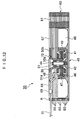
- FIG. 12 is a sectional view of the axial fan motor according to the second embodiment which employs the casing formed through use of the metal plates B3, and corresponds to FIG. 8, which shows the axial fan motor according to the first embodiment.
- Structural features similar to those of the first embodiment are denoted by common reference numerals.
- the casing 60 of the axial fan motor 30 of the second embodiment is composed of a single first metal plate A, which is the outermost layer located at the air exhaust side of a fan, and a plurality of second metal plates B. All of the second metal plates B are the metal plates B3 shown in FIG. 7.
- the metal plate B3 includes a peripheral portion 62B3 having a circular inner edge 65B3 and a single cutout portion 71 formed through the peripheral portion 62B3 being partially cut off and assumes an outline equal in size to the outline of the metal plate B1.
- the cutout portion 71 is formed at one side of the square shape of the metal plate B3.
- a plurality of metal plates B3 are laminated underneath the first metal plate A to thereby constitute the casing 60.
- the metal plates B3 are laminated such that the angular positions of the cutout portions 71 of the metal plates B3 are successively shifted in the same circumferential direction and such that a phase shift of a predetermined angle 90 degrees is produced between two adjacent cutout portions 71.
- the cutout portions 71 of the metal plates B3 are arranged all around the casing.
- the cutout portion 71 of the metal plate B3 appears at the same position every five metal plates B3.
- the angle by which the cutout portions 71 are shifted from each other is not limited to 90 degrees. As shown in FIG. 13, the cutout portions 71 can be shifted from each other by 180 degrees. In this case, the cutout portion 71 appears at the same position every other metal plate B3. When the cutout portions 71 are to be shifted from each other by 90 degrees, the first metal plate A and the metal plates B3 must assume a square outline as viewed from above.
- the axial fan motor 30 of the second embodiment differs from that of the first embodiment in the above-mentioned structural feature, but is similar to that of the first embodiment in other structural features. Thus, other structural features are not described.
- the second embodiment yields the following effects.
- All of the plurality of second metal plates B are the metal plates B3. Since metal plates of merely a single kind; i.e., merely the metal plates B3, are used as the second metal plates B, manufacture of the casing 60 is significantly facilitated. Since cooling air flows between the interior of the casing 60 and the exterior of the casing 60 through the cutout portions 71 of the metal plates B3, the efficiency of releasing heat from the casing 60 is more enhanced to thereby more enhance the cooling efficiency of the heat sink 10, as compared to the first embodiment.
- the metal plates B3 are laminated such that the angular positions of the cutout portions 71 of the metal plates B3 are successively shifted in the same circumferential direction and such that a phase shift of a predetermined angle is produced between two adjacent cutout portions 71. Since cooling air flows between the interior of the casing 60 and the exterior of the casing 60 through the cutout portions 71 of the metal plates B3 which are circumferentially arranged at predetermined intervals, heat can be uniformly released from the casing 60 to thereby lessen thermal stress in the casing 60. Thus, the durability of the casing 60 can be enhanced.
- the predetermined angle is 90 degrees
- the cutout portions 71 of the metal plates B3 are arranged all around the casing 60.
- the second embodiment yields other effects similar to those which the first embodiment yields.
- FIG. 6 shows a metal plate B2 which is a kind of second metal plate B and is one of layers constituting the casing of an axial fan motor according to the third embodiment.
- FIG. 6A is a plan view of the metal plate B2
- FIG. 6B is a side view of the metal plate B2.
- FIG. 14 is a sectional view of the axial fan motor according to the third embodiment which employs the casing formed through combined use of the metal plates B2 and B1, taken along line XIV-XIV of FIG. 15, and corresponds to FIG. 8, which shows the axial fan motor according to the first embodiment.
- FIG. 15 is a plan view of the axial fan motor according to the third embodiment. Structural features similar to those of the first embodiment are denoted by common reference numerals.
- the casing 60 of the axial fan motor 30 of the third embodiment is composed of a single first metal plate A, which is the outermost layer located at the air exhaust side of a fan, and a plurality of second metal plates B.
- the plurality of second metal plates B are composed of the metal plates B1 shown in FIG. 5 and the metal plates B2 shown in FIG. 6 such that the metal plates B1 and B2 are laminated alternately.
- the metal plate B2 includes a peripheral portion 62B2 having a circular inner edge 65B2 and assumes an outline of greater size than the outline of the metal plate B1.
- the casing 60 is configured such that such metal plates B2 and the metal plates B1 used in the first embodiment are laminated alternately under the first metal plate A. Accordingly, the side walls of the casing 60 assume such a rugged profile that peripheral edge portions of the metal plates B2 project beyond the peripheral edges of the metal plates B1.
- the axial fan motor 30 of the third embodiment differs from that of the first embodiment in the above-mentioned structural feature, but is similar to that of the first embodiment in other structural features. Thus, other structural features are not described.
- the third embodiment yields the following effects.
- the plurality of second metal plates B are composed of the metal plates B1 and B2 such that the metal plates B1 and B2 are laminated alternately.
- peripheral edge portions of the metal plates B2 which project beyond the peripheral edges of the metal plates B1 serve as fins.
- the efficiency of releasing heat from the casing 60 is more enhanced to thereby more enhance the cooling efficiency of the heat sink.
- the third embodiment yields other effects similar to those which the first embodiment yields.
- the third embodiment uses the first metal plate A and the metal plates B1 used in the first embodiment and assuming the same outline.
- the present invention is not limited thereto.
- the outline of the first metal plate A can be expanded to that of the metal plate B2, to thereby improve the appearance of the axial fan motor 30.
- FIG. 17 is a sectional view of an axial fan motor according to the fourth embodiment and corresponds to FIG. 16 showing a modification of the third embodiment. Structural features similar to those of the third embodiment are denoted by common reference numerals.
- the casing 60 of the axial fan motor 30 of the fourth embodiment is composed of a single first metal plate A, which is the outermost layer located at the air exhaust side of a fan, and a plurality of second metal plates B.
- the plurality of second metal plates B are composed of the metal plates B2 and the metal plates B3 such that the metal plates B2 and B3 are laminated alternately.
- the metal plates B3 are used in place of the metal plates B1 used in the casing 60 of the axial fan motor 30 of the third embodiment.
- the plurality of metal plates B3 are arranged such that the cutout portions 71 are oriented in the same direction.
- the first metal plate A used in the present embodiment is the expanded metal plate A used in the modification (see FIG. 16) of the third embodiment.
- the axial fan motor 30 of the fourth embodiment differs from that of the third embodiment in the above-mentioned structural feature, but is similar to that of the third embodiment in other structural features. Thus, other structural features are not described.
- the fourth embodiment yields the following effects.
- the plurality of second metal plates B are composed the metal plates B2 and B3 such that the metal plates B2 and B3 are laminated alternately. Since peripheral edge portions of the metal plates B2 which project beyond the peripheral edges of the metal plates B3 serve as fins, and cooling air flows between the interior of the casing 60 and the exterior of the casing 60 through the cutout portions 71 of the metal plates B3, the efficiency of releasing heat from the casing 60 is greatly enhanced to thereby greatly enhance the cooling efficiency of the heat sink. Also, the fourth embodiment yields other effects similar to those which the third embodiment yields.
- the axial fan motor 30 of the fifth embodiment (not shown) is a modification of the axial fan motor 30 of the fourth embodiment.
- the metal plates B2 and B3 are alternately laminated such that the angular positions of the cutout portions 71 of the metal plates B3 are successively shifted in the same circumferential direction and such that a phase shift of a predetermined angle is produced between two adjacent cutout portions.
- the predetermined angle is 90 degrees or 180 degrees as in the case of the second embodiment.
- the axial fan motor 30 of the fifth embodiment differs from that of the fourth embodiment in the above-mentioned structural feature, but is similar to that of the fourth embodiment in other structural features. Thus, other structural features are not described.
- the fifth embodiment yields the following effects. Since cooling air flows between the interior of the casing 60 and the exterior of the casing 60 through the cutout portions 71 of the metal plates B3 which are circumferentially arranged at predetermined intervals, heat can be uniformly released from the casing 60 to thereby lessen thermal stress in the casing 60. Thus, the durability of the casing 60 can be enhanced. Particularly, when the predetermined angle is 90 degrees, every time four metal plates B3 are laminated, the cutout portions 71 of the metal plates B3 are arranged all around the casing 60. Thus, the above-mentioned effects are further enhanced. Also, the fifth embodiment yields other effects similar to those which the fourth embodiment yields.
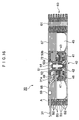
- FIG. 18 is a sectional view of an axial fan motor according to the sixth embodiment and corresponds to FIG. 8 showing the first embodiment. Structural features similar to those of the first embodiment are denoted by common reference numerals.
- the axial fan motor 30 of the sixth embodiment is configured such that the first metal plate A of the casing 60 and the bearing holder 50 are integrally formed of the same metal.
- the axial fan motor 30 of the sixth embodiment differs from that of the first embodiment in the above-mentioned structural feature, but is similar to that of the first embodiment in other structural features. Thus, other structural features are not described.
- the above-mentioned structural feature more simplifies assembly of the casing 60 and the main body 40 (the stationary portion 41 and the rotary portion 42) of the axial fan motor 30 to thereby more simplify the assembled structure of the axial fan motor 30.
- the sixth embodiment yields other effects similar to those which the first embodiment yields.
- the casing 60 of the axial fan motor 30 of the seventh embodiment is configured such that a plurality of metal plates and a single or a plurality of resin plates are arranged in layers(laminated).
- the single or plurality of resin plates include at least a single resin plate C, which is the outermost layer located at the air exhaust side of a fan.
- the resin plate C (not shown) includes a peripheral portion having a circular inner edge; a central portion having a circular outer edge; and a plurality of arm portions for connecting the peripheral portion and the central portion.
- a bearing holder of a rotary shaft of the fan is attached to the central portion.
- the casing 60 may not include resin plates except the outermost resin plate C located at the air exhaust side of the fan.
- the axial fan motor 30 of the seventh embodiment differs from that of the first embodiment in the above-mentioned structural feature, but is similar to that of the first embodiment in other structural features. Thus, other structural features are not described.
- the casing can be manufactured from a plurality of metal plates, a single or a plurality of resin plates, and connection means (such as rivets, bolts, or adhesive), the following effect is yielded.
- the casing 60 can be manufactured without the involvement of such machining processes, thereby facilitating manufacture and enhancing productivity.
- the seventh embodiment yields other effects similar to those which the first embodiment yields.
- the axial fan motor 30 of the eighth embodiment is configured such that a bearing holder and a resin plate C which partially constitutes the casing 60 and is the outermost layer located at the air exhaust side of a fan are integrally formed of the same resin through molding.
- the axial fan motor 30 of the eighth embodiment differs from that of the seventh embodiment in the above-mentioned structural feature, but is similar to that of the seventh embodiment in other structural features. Thus, other structural features are not described.
- the above-mentioned structural feature more simplifies assembly of the casing 60 and the main body 40 (the stationary portion 41 and the rotary portion 42) of the axial fan motor 30 to thereby more simplify the assembled structure of the axial fan motor 30.
- the eighth embodiment yields other effects similar to those which the seventh embodiment yields.
- the axial fan motor 30 of the ninth embodiment includes air rectification means for straightening cooling air.
- the air rectification means (not shown) is disposed between the axial fan motor 30 and the shroud 20 and assumes the form of an air rectification cylinder equipped with a plurality of air rectification blades.
- the axial fan motor 30 of the ninth embodiment differs from that of the first embodiment in the above-mentioned structural feature, but is similar to that of the first embodiment in other structural features. Thus, other structural features are not described.
- cooling air which is caused to flow by the axial fan motor 30 of the ninth embodiment involves no whirls in contrast to the first embodiment. Also, as compared with the first embodiment, an adverse effect of the main body 40 (the stationary portion 41 and the rotary portion 42) located at a central portion of the axial fan motor 30 on cooling air flow can be greatly eased, thereby greatly suppressing a phenomenon that an air flow rate at a central portion of the axial fan motor 30 becomes lower than that at a peripheral portion of the axial fan motor 30. Thus, the cooling air can reach deep into the heat sink 10 along its fins 12, whereby the heat sink 10 can be cooled more uniformly to thereby further enhance the cooling efficiency of the heat sink 10. Also, the ninth embodiment yields other effects similar to those which the first embodiment yields.
- the air rectification means is interposed between the axial fan motor 30 and the shroud 20.
- the present invention is not limited thereto.
- a plurality of air rectification blades can be disposed at a central cutout portion of the support base 21 of the shroud 20.
- the cooling unit 1 equipped with the axial fan motor 30 is configured in the following manner.
- the shroud 20 and a single plate (a metal plate or a resin plate) which is one of layers constituting the casing 60 of the axial fan motor 30 and is the outermost layer located at the air intake side of a fan are integrally formed of the same material.
- the cooling unit 1 equipped with the axial fan motor 30 according to the tenth embodiment differs from that of the first embodiment in the above-mentioned structural feature, but is similar to that of the first embodiment in other structural features. Thus, other structural features are not described.
- the tenth embodiment facilitates assembly of the shroud 20 and the casing 60 of the axial fan motor 30.
- the axial fan motor 30 can be readily mounted above the heat sink 10.
- the tenth embodiment yields other effects similar to those which the first embodiment yields.
Landscapes
- Engineering & Computer Science (AREA)
- Power Engineering (AREA)
- Mechanical Engineering (AREA)
- General Engineering & Computer Science (AREA)
- Physics & Mathematics (AREA)
- Thermal Sciences (AREA)
- Microelectronics & Electronic Packaging (AREA)
- Motor Or Generator Cooling System (AREA)
- Structures Of Non-Positive Displacement Pumps (AREA)
- Cooling Or The Like Of Electrical Apparatus (AREA)
- Motor Or Generator Frames (AREA)
- Connection Of Motors, Electrical Generators, Mechanical Devices, And The Like (AREA)
Abstract
Description
Claims (17)
- An axial fan motor for a cooling unit, adapted to air-cool a heat sink of a heating element such as CPU and thermally connected to the heat sink, said axial fan motor comprising a casing formed of a plurality of laminated metal plates.
- An axial fan motor for a cooling unit according to Claim 1, wherein
said plurality of metal plates include a single first metal plate, which is an outermost layer located at an air exhaust side of a fan, and a plurality of second metal plates;
said first metal plate includes a peripheral portion having a circular inner edge, a central portion having a circular outer edge, and a plurality of arm portions for connecting the peripheral portion and the central portion;
a bearing holder for supporting a rotary shaft of the fan is attached to the central portion; and
each of said plurality of second metal plates is(1) a first-type second metal plate which includes only a peripheral portion having a circular inner edge,(2) a second-type second metal plate which includes only a peripheral portion having a circular inner edge and assumes an outline of greater size than the outline of said first-type second metal plate, or(3) a third-type second metal plate which includes only a peripheral portion having a circular inner edge and a single cutout portion formed in the peripheral portion and assumes an outline substantially equal in size to the outline of said first-type second metal plate. - An axial fan motor for a cooling unit according to Claim 2, wherein all of said plurality of second metal plates are said first-type second metal plates.
- An axial fan motor for a cooling unit according to Claim 2, wherein all of said plurality of second metal plates are said third-type second metal plates.
- An axial fan motor for a cooling unit according to Claim 4, wherein said third-type second metal plates are arranged such that the angular positions of the cutout portions of said third-type second metal plates are successively shifted in the same circumferential direction and such that a phase shift of a predetermined angle is produced between two adjacent cutout portions.
- An axial fan motor for a cooling unit according to Claim 2, wherein said plurality of second metal plates comprise said first-type and second-type second metal plates such that said first-type and second-type second metal plates are laminated alternately.
- An axial fan motor for a cooling unit according to Claim 2, wherein said plurality of second metal plates comprise said second-type and third-type second metal plates such that said second-type and third-type second metal plates are laminated alternately.
- An axial fan motor for a cooling unit according to Claim 7, wherein said second-type and third-type second metal plates are arranged alternately such that the angular positions of the cutout portions of said third-type second metal plates are successively shifted in the same circumferential direction and such that a phase shift of a predetermined angle is produced between two adjacent cutout portions.
- An axial fan motor for a cooling unit according to Claim 2, wherein said first metal plate and the bearing holder are integrally formed of the same metal.
- An axial fan motor for a cooling unit, adapted to air-cool a heat sink of a heating element such as CPU and thermally connected to the heat sink, said axial fan motor comprising:a casing formed of a plurality of metal plates and a single or a plurality of resin plates, said metal plates and said resin plates being laminated.
- An axial fan motor for a cooling unit according to Claim 10, wherein said single or plurality of resin plates comprise at least a single resin plate, which is an outermost layer located at an air exhaust side of a fan;
said resin plate includes a peripheral portion having a circular inner edge; a central portion having a circular outer edge; and a plurality of arm portions for connecting the peripheral portion and the central portion; and
a bearing holder for supporting a rotary shaft of the fan is attached to the central portion. - An axial fan motor for a cooling unit according to Claim 11, wherein said resin plate and the bearing holder are integrally formed of the same resin.
- An axial fan motor for a cooling unit according to Claim 5 or 8, wherein the predetermined angle is 90 degrees.
- An axial fan motor for a cooling unit according to Claim 2 or 11, wherein one of said arm portions has a window formed therein so as to allow looking therethrough at least at a terminal of a lead wire, and holder means for holding a lead wire.
- An axial fan motor for a cooling unit according to Claim 1 or 10, further comprising air rectification means.
- An axial fan motor for a cooling unit according to Claim 15, wherein said air rectification means is disposed between said axial fan motor and the heat sink and assumes the form of an air-rectification cylinder equipped with a plurality of air rectification blades.
- A cooling unit, comprising:an axial fan motor according to Claim 1 or 10; anda shroud for mounting said axial fan motor above a heat sink, whereinsaid shroud includes a support base having a central portion cut out and on which a casing of said axial fan motor is mounted, and a plurality of legs extending downward from a plurality of positions on a peripheral edge of said support base;said support base covers and is thermally connected to the heat sink, and end portions of said legs are engaged with a base of the heat sink, whereby said shroud is fixedly attached to the heat sink; andsaid shroud and a plate serving as an outermost layer located at an air intake side of a fan of said axial fan motor and partially constituting the casing of said axial fan motor are integrally formed of the same material.
Applications Claiming Priority (2)
| Application Number | Priority Date | Filing Date | Title |
|---|---|---|---|
| JP2001007125A JP3503822B2 (en) | 2001-01-16 | 2001-01-16 | Axial fan motor and cooling device |
| JP2001007125 | 2001-01-16 |
Publications (3)
| Publication Number | Publication Date |
|---|---|
| EP1229776A2 true EP1229776A2 (en) | 2002-08-07 |
| EP1229776A3 EP1229776A3 (en) | 2004-04-14 |
| EP1229776B1 EP1229776B1 (en) | 2006-04-19 |
Family
ID=18874917
Family Applications (1)
| Application Number | Title | Priority Date | Filing Date |
|---|---|---|---|
| EP02000614A Expired - Lifetime EP1229776B1 (en) | 2001-01-16 | 2002-01-10 | Axial fan motor and cooling unit |
Country Status (7)
| Country | Link |
|---|---|
| US (3) | US7034418B2 (en) |
| EP (1) | EP1229776B1 (en) |
| JP (1) | JP3503822B2 (en) |
| CN (1) | CN100414120C (en) |
| AT (1) | ATE324026T1 (en) |
| DE (1) | DE60210687T2 (en) |
| TW (1) | TWI257835B (en) |
Families Citing this family (95)
| Publication number | Priority date | Publication date | Assignee | Title |
|---|---|---|---|---|
| JP3503822B2 (en) * | 2001-01-16 | 2004-03-08 | ミネベア株式会社 | Axial fan motor and cooling device |
| US6646341B2 (en) * | 2002-02-20 | 2003-11-11 | Hewelett-Packard Development Company, L.P. | Heat sink apparatus utilizing the heat sink shroud to dissipate heat |
| US6892800B2 (en) * | 2002-12-31 | 2005-05-17 | International Business Machines Corporation | Omnidirectional fan-heatsinks |
| US20060138905A1 (en) * | 2004-12-28 | 2006-06-29 | Gonzales Christopher A | Piezoelectric fan for an integrated circuit chip |
| TW200734549A (en) * | 2006-03-10 | 2007-09-16 | Sunonwealth Electr Mach Ind Co | Cooling fan structure |
| TWI326333B (en) * | 2006-12-26 | 2010-06-21 | Sunonwealth Electr Mach Ind Co | Low air-noise fan housing structure |
| JP2008267176A (en) * | 2007-04-17 | 2008-11-06 | Sony Corp | Axial fan device, housing and electronic device |
| GB2452593A (en) | 2007-09-04 | 2009-03-11 | Dyson Technology Ltd | A fan |
| US8212443B2 (en) * | 2007-11-14 | 2012-07-03 | Delta Electronics, Inc. | Motor and housing thereof |
| TWM334624U (en) * | 2008-01-02 | 2008-06-11 | Cooler Master Co Ltd | Heat sink of display card |
| US7990005B2 (en) * | 2008-02-07 | 2011-08-02 | Atlas Dynamic Devices, Llc | Power transmission tool and system |
| US8742643B2 (en) * | 2008-05-16 | 2014-06-03 | Schlumberger Technology Corporation | Commutation system for a DC motor |
| GB2463698B (en) * | 2008-09-23 | 2010-12-01 | Dyson Technology Ltd | A fan |
| GB2464736A (en) | 2008-10-25 | 2010-04-28 | Dyson Technology Ltd | Fan with a filter |
| EP2404118B1 (en) | 2009-03-04 | 2017-05-31 | Dyson Technology Limited | A fan |
| GB2468325A (en) * | 2009-03-04 | 2010-09-08 | Dyson Technology Ltd | Height adjustable fan with nozzle |
| PL2276933T3 (en) | 2009-03-04 | 2011-10-31 | Dyson Technology Ltd | A fan |
| GB2468329A (en) * | 2009-03-04 | 2010-09-08 | Dyson Technology Ltd | Fan assembly |
| GB2468312A (en) * | 2009-03-04 | 2010-09-08 | Dyson Technology Ltd | Fan assembly |
| GB2468323A (en) * | 2009-03-04 | 2010-09-08 | Dyson Technology Ltd | Fan assembly |
| GB2468317A (en) * | 2009-03-04 | 2010-09-08 | Dyson Technology Ltd | Height adjustable and oscillating fan |
| GB2468315A (en) * | 2009-03-04 | 2010-09-08 | Dyson Technology Ltd | Tilting fan |
| GB2468320C (en) | 2009-03-04 | 2011-06-01 | Dyson Technology Ltd | Tilting fan |
| GB2468322B (en) * | 2009-03-04 | 2011-03-16 | Dyson Technology Ltd | Tilting fan stand |
| GB2468331B (en) | 2009-03-04 | 2011-02-16 | Dyson Technology Ltd | A fan |
| CN201884310U (en) * | 2009-03-04 | 2011-06-29 | 戴森技术有限公司 | fan assembly |
| GB0903682D0 (en) | 2009-03-04 | 2009-04-15 | Dyson Technology Ltd | A fan |
| EP2414738B1 (en) * | 2009-03-04 | 2013-10-09 | Dyson Technology Limited | Humidifying apparatus |
| GB2468326A (en) * | 2009-03-04 | 2010-09-08 | Dyson Technology Ltd | Telescopic pedestal fan |
| WO2010122735A1 (en) * | 2009-04-23 | 2010-10-28 | 株式会社ヴァレオサーマルシステムズ | Driving motor |
| GB0919473D0 (en) * | 2009-11-06 | 2009-12-23 | Dyson Technology Ltd | A fan |
| US8684708B2 (en) * | 2009-12-16 | 2014-04-01 | Asia Vital Components Co., Ltd. | Fan stator cover structure |
| GB2478927B (en) | 2010-03-23 | 2016-09-14 | Dyson Technology Ltd | Portable fan with filter unit |
| GB2478925A (en) * | 2010-03-23 | 2011-09-28 | Dyson Technology Ltd | External filter for a fan |
| ES2553148T3 (en) | 2010-05-27 | 2015-12-04 | Dyson Technology Limited | Air blowing device by means of a narrow slit nozzle assembly |
| GB2482547A (en) | 2010-08-06 | 2012-02-08 | Dyson Technology Ltd | A fan assembly with a heater |
| GB2482548A (en) | 2010-08-06 | 2012-02-08 | Dyson Technology Ltd | A fan assembly with a heater |
| GB2482549A (en) | 2010-08-06 | 2012-02-08 | Dyson Technology Ltd | A fan assembly with a heater |
| GB2483448B (en) | 2010-09-07 | 2015-12-02 | Dyson Technology Ltd | A fan |
| US10100836B2 (en) | 2010-10-13 | 2018-10-16 | Dyson Technology Limited | Fan assembly |
| DK2630373T3 (en) | 2010-10-18 | 2017-04-10 | Dyson Technology Ltd | FAN UNIT |
| GB2484670B (en) | 2010-10-18 | 2018-04-25 | Dyson Technology Ltd | A fan assembly |
| JP5778293B2 (en) | 2010-11-02 | 2015-09-16 | ダイソン テクノロジー リミテッド | Blower assembly |
| GB2486019B (en) | 2010-12-02 | 2013-02-20 | Dyson Technology Ltd | A fan |
| KR101595869B1 (en) | 2011-07-27 | 2016-02-19 | 다이슨 테크놀러지 리미티드 | A fan assembly |
| GB2493506B (en) | 2011-07-27 | 2013-09-11 | Dyson Technology Ltd | A fan assembly |
| TWI448048B (en) * | 2011-09-01 | 2014-08-01 | Sunonwealth Electr Mach Ind Co | Miniaturized fan and a cooling fan utilizing the same |
| GB201119500D0 (en) | 2011-11-11 | 2011-12-21 | Dyson Technology Ltd | A fan assembly |
| GB2496877B (en) | 2011-11-24 | 2014-05-07 | Dyson Technology Ltd | A fan assembly |
| AU2011253643B2 (en) * | 2011-11-25 | 2013-10-31 | Hunter Pacific International Pty Ltd | Mounting Assembly For An Electric Fan |
| GB2498547B (en) | 2012-01-19 | 2015-02-18 | Dyson Technology Ltd | A fan |
| GB2499042A (en) | 2012-02-06 | 2013-08-07 | Dyson Technology Ltd | A nozzle for a fan assembly |
| GB2499044B (en) | 2012-02-06 | 2014-03-19 | Dyson Technology Ltd | A fan |
| GB2499041A (en) | 2012-02-06 | 2013-08-07 | Dyson Technology Ltd | Bladeless fan including an ionizer |
| GB2500011B (en) | 2012-03-06 | 2016-07-06 | Dyson Technology Ltd | A Humidifying Apparatus |
| GB2500010B (en) | 2012-03-06 | 2016-08-24 | Dyson Technology Ltd | A humidifying apparatus |
| GB2500012B (en) | 2012-03-06 | 2016-07-06 | Dyson Technology Ltd | A Humidifying Apparatus |
| GB2500017B (en) | 2012-03-06 | 2015-07-29 | Dyson Technology Ltd | A Humidifying Apparatus |
| KR101699293B1 (en) | 2012-03-06 | 2017-01-24 | 다이슨 테크놀러지 리미티드 | A fan assembly |
| GB2500005B (en) | 2012-03-06 | 2014-08-27 | Dyson Technology Ltd | A method of generating a humid air flow |
| GB2500903B (en) | 2012-04-04 | 2015-06-24 | Dyson Technology Ltd | Heating apparatus |
| GB2501301B (en) | 2012-04-19 | 2016-02-03 | Dyson Technology Ltd | A fan assembly |
| WO2013171452A2 (en) | 2012-05-16 | 2013-11-21 | Dyson Technology Limited | A fan |
| GB2532557B (en) | 2012-05-16 | 2017-01-11 | Dyson Technology Ltd | A fan comprsing means for suppressing noise |
| GB2502103B (en) | 2012-05-16 | 2015-09-23 | Dyson Technology Ltd | A fan |
| GB2503907B (en) | 2012-07-11 | 2014-05-28 | Dyson Technology Ltd | A fan assembly |
| AU350140S (en) | 2013-01-18 | 2013-08-13 | Dyson Technology Ltd | Humidifier or fan |
| AU350181S (en) | 2013-01-18 | 2013-08-15 | Dyson Technology Ltd | Humidifier or fan |
| BR302013003358S1 (en) | 2013-01-18 | 2014-11-25 | Dyson Technology Ltd | CONFIGURATION APPLIED ON HUMIDIFIER |
| AU350179S (en) | 2013-01-18 | 2013-08-15 | Dyson Technology Ltd | Humidifier or fan |
| GB2510195B (en) | 2013-01-29 | 2016-04-27 | Dyson Technology Ltd | A fan assembly |
| EP2951507A2 (en) | 2013-01-29 | 2015-12-09 | Dyson Technology Limited | A fan assembly |
| USD729372S1 (en) | 2013-03-07 | 2015-05-12 | Dyson Technology Limited | Fan |
| CA152657S (en) | 2013-03-07 | 2014-05-20 | Dyson Technology Ltd | Fan |
| CA152655S (en) | 2013-03-07 | 2014-05-20 | Dyson Technology Ltd | Fan |
| BR302013004394S1 (en) | 2013-03-07 | 2014-12-02 | Dyson Technology Ltd | CONFIGURATION APPLIED TO FAN |
| CA152658S (en) | 2013-03-07 | 2014-05-20 | Dyson Technology Ltd | Fan |
| CA152656S (en) | 2013-03-07 | 2014-05-20 | Dyson Technology Ltd | Fan |
| CN104235064B (en) * | 2013-06-07 | 2018-01-26 | 台达电子工业股份有限公司 | Fan and impeller thereof |
| GB2530906B (en) | 2013-07-09 | 2017-05-10 | Dyson Technology Ltd | A fan assembly |
| CA154723S (en) | 2013-08-01 | 2015-02-16 | Dyson Technology Ltd | Fan |
| CA154722S (en) | 2013-08-01 | 2015-02-16 | Dyson Technology Ltd | Fan |
| TWD172707S (en) | 2013-08-01 | 2015-12-21 | 戴森科技有限公司 | A fan |
| GB2518638B (en) | 2013-09-26 | 2016-10-12 | Dyson Technology Ltd | Humidifying apparatus |
| GB2528708B (en) | 2014-07-29 | 2016-06-29 | Dyson Technology Ltd | A fan assembly |
| GB2528709B (en) | 2014-07-29 | 2017-02-08 | Dyson Technology Ltd | Humidifying apparatus |
| GB2528704A (en) | 2014-07-29 | 2016-02-03 | Dyson Technology Ltd | Humidifying apparatus |
| US10136559B2 (en) * | 2016-06-20 | 2018-11-20 | Baidu Usa Llc | Liquid-assisted air cooling of electronic racks with modular fan and heat exchangers |
| JP6741993B2 (en) * | 2018-06-11 | 2020-08-19 | パナソニックIpマネジメント株式会社 | Heat dissipation device |
| CN209150811U (en) * | 2018-12-10 | 2019-07-23 | 日本电产株式会社 | Stator elements, stator assemblies, motors and electromechanical devices |
| JP7353132B2 (en) * | 2019-10-31 | 2023-09-29 | 新光電気工業株式会社 | Loop type heat pipe and its manufacturing method |
| JP7705704B2 (en) * | 2020-03-03 | 2025-07-10 | Hoya株式会社 | Cooling device and light irradiation device |
| JP7799419B2 (en) * | 2021-10-01 | 2026-01-15 | ミネベアミツミ株式会社 | motor |
| CN115267268B (en) * | 2022-05-27 | 2024-10-29 | 苏州联讯仪器股份有限公司 | Chip testing device |
| TWI851444B (en) * | 2023-10-12 | 2024-08-01 | 技鋼科技股份有限公司 | Fan module |
Family Cites Families (32)
| Publication number | Priority date | Publication date | Assignee | Title |
|---|---|---|---|---|
| JPS60204236A (en) | 1984-03-27 | 1985-10-15 | Matsushita Electric Ind Co Ltd | Motor |
| JPH01278248A (en) | 1988-04-30 | 1989-11-08 | Taiyo Densan Kk | Fan motor |
| JPH03277151A (en) | 1990-03-27 | 1991-12-09 | Nippon Densan Corp | Fan |
| JPH0417556A (en) | 1990-05-08 | 1992-01-22 | Tamagawa Seiki Co Ltd | Stator structure of brushless DC motor |
| US5197854A (en) * | 1991-09-05 | 1993-03-30 | Industrial Design Laboratories, Inc. | Axial flow fan |
| US5288203A (en) * | 1992-10-23 | 1994-02-22 | Thomas Daniel L | Low profile fan body with heat transfer characteristics |
| JP2901867B2 (en) * | 1993-03-19 | 1999-06-07 | 富士通株式会社 | Heat sink and heat sink mounting structure |
| US5335722A (en) * | 1993-09-30 | 1994-08-09 | Global Win Technology Co., Ltd | Cooling assembly for an integrated circuit |
| US5407324A (en) * | 1993-12-30 | 1995-04-18 | Compaq Computer Corporation | Side-vented axial fan and associated fabrication methods |
| US5583746A (en) * | 1994-12-12 | 1996-12-10 | Tennmax Trading Corp. | Heat sink assembly for a central processing unit of a computer |
| US5502619A (en) * | 1994-12-12 | 1996-03-26 | Tennmax Trading Corp. | Heat sink assembly for computer chips |
| US5896917A (en) * | 1996-02-22 | 1999-04-27 | Lemont Aircraft Corporation | Active heat sink structure with flow augmenting rings and method for removing heat |
| US5822186A (en) | 1996-02-23 | 1998-10-13 | Apple Computer, Inc. | Auxiliary electrical component utilized on the exterior of an electrical device that can be removed when the electrical device is powered |
| JPH105438A (en) | 1996-06-24 | 1998-01-13 | Osamu Katsura | Control system for ic card for pachinko ball dispenser |
| JP3188397B2 (en) * | 1996-07-04 | 2001-07-16 | 松下電器産業株式会社 | Blower |
| JPH1054386A (en) | 1996-08-09 | 1998-02-24 | Sanyo Denki Co Ltd | fan |
| JPH10154889A (en) | 1996-11-25 | 1998-06-09 | Yaskawa Electric Corp | Cooling device |
| US20010023756A1 (en) * | 1996-12-03 | 2001-09-27 | Naoto Tanaka | Assembled structure having an enlarged heat transfer area for heat radiation therefrom |
| JPH10163022A (en) * | 1996-12-03 | 1998-06-19 | Minebea Co Ltd | Laminated assembly with increased heat dissipation area |
| US6132171A (en) * | 1997-06-10 | 2000-10-17 | Matsushita Electric Industrial Co., Ltd. | Blower and method for molding housing thereof |
| JPH1175340A (en) | 1997-06-17 | 1999-03-16 | Nippon Densan Corp | motor |
| US5988995A (en) * | 1997-09-17 | 1999-11-23 | Sunonwealth Electric Machine Industry Co., Ltd. | Housings for miniature fans |
| JPH1198755A (en) | 1997-09-25 | 1999-04-09 | Aisin Aw Co Ltd | Driver for electric vehicle |
| JP3483447B2 (en) * | 1998-01-08 | 2004-01-06 | 松下電器産業株式会社 | Blower |
| JP3345365B2 (en) | 1999-01-29 | 2002-11-18 | マブチモーター株式会社 | Small motor |
| JP3856973B2 (en) | 1999-02-02 | 2006-12-13 | 日本電産株式会社 | Fan device |
| US6193205B1 (en) * | 1999-05-03 | 2001-02-27 | Tennmax Trading Corp. | Retainer for a BGA fan |
| JP2000341902A (en) | 1999-05-26 | 2000-12-08 | Namiki Precision Jewel Co Ltd | Fan motor with heat sink and small flat motor |
| JP4697501B2 (en) | 2000-07-25 | 2011-06-08 | ミネベア株式会社 | Rectifier blade |
| JP3503822B2 (en) * | 2001-01-16 | 2004-03-08 | ミネベア株式会社 | Axial fan motor and cooling device |
| JP2002224795A (en) | 2001-02-06 | 2002-08-13 | Mitsubishi Automob Eng Co Ltd | Cylinder head manufacturing method |
| US6958562B1 (en) * | 2004-02-09 | 2005-10-25 | Vargo James R | Motor stator and heat sink system |
-
2001
- 2001-01-16 JP JP2001007125A patent/JP3503822B2/en not_active Expired - Fee Related
-
2002
- 2002-01-08 TW TW091100128A patent/TWI257835B/en active
- 2002-01-09 US US10/040,470 patent/US7034418B2/en not_active Expired - Fee Related
- 2002-01-10 EP EP02000614A patent/EP1229776B1/en not_active Expired - Lifetime
- 2002-01-10 AT AT02000614T patent/ATE324026T1/en not_active IP Right Cessation
- 2002-01-10 DE DE60210687T patent/DE60210687T2/en not_active Expired - Lifetime
- 2002-01-15 CN CNB02101681XA patent/CN100414120C/en not_active Expired - Fee Related
-
2005
- 2005-11-18 US US11/281,460 patent/US7157819B2/en not_active Expired - Fee Related
-
2006
- 2006-10-18 US US11/582,323 patent/US7245056B2/en not_active Expired - Fee Related
Also Published As
| Publication number | Publication date |
|---|---|
| JP3503822B2 (en) | 2004-03-08 |
| US20020093255A1 (en) | 2002-07-18 |
| US7034418B2 (en) | 2006-04-25 |
| EP1229776B1 (en) | 2006-04-19 |
| US20070035189A1 (en) | 2007-02-15 |
| DE60210687T2 (en) | 2007-01-18 |
| CN1366146A (en) | 2002-08-28 |
| JP2002218703A (en) | 2002-08-02 |
| CN100414120C (en) | 2008-08-27 |
| US7157819B2 (en) | 2007-01-02 |
| TWI257835B (en) | 2006-07-01 |
| EP1229776A3 (en) | 2004-04-14 |
| US7245056B2 (en) | 2007-07-17 |
| ATE324026T1 (en) | 2006-05-15 |
| DE60210687D1 (en) | 2006-05-24 |
| US20060066161A1 (en) | 2006-03-30 |
Similar Documents
| Publication | Publication Date | Title |
|---|---|---|
| EP1229776B1 (en) | Axial fan motor and cooling unit | |
| US5957659A (en) | Heat sink apparatus | |
| JP4904894B2 (en) | Axial fan | |
| US8113775B2 (en) | Axial flow fan | |
| US7581307B2 (en) | Method of making an electric machine having an electronics mount secured by an interference fit | |
| JP5570572B2 (en) | Mechanical and electric integrated drive | |
| EP1760863A2 (en) | Automotive alternator with rectifier having high-strength heat sinks | |
| US20070080604A1 (en) | Electric fan | |
| EP1077333A2 (en) | Cooling module for an electronically controlled engine | |
| JPH0865933A (en) | Motor rotor core | |
| JP4306058B2 (en) | Vehicle alternator | |
| JPH09103041A (en) | Rotating electric machine | |
| JP5993603B2 (en) | Blower | |
| US8485781B2 (en) | Axial flow fan | |
| JP4834675B2 (en) | Rotor, electrical equipment including rotor, and cryogenic pump system | |
| JP2936747B2 (en) | AC generator for vehicles | |
| JPH118951A (en) | Fan motor of axial space type | |
| JP2001339926A (en) | Power supply mechanism of flat brushless vibration motor and method of manufacturing chip substrate for drive circuit | |
| JP2004080916A (en) | Alternator | |
| JPH09247885A (en) | Foot-mounted electric motor | |
| TWI384722B (en) | Miniature motor | |
| EP2251961B1 (en) | Carrier for electronic components, and electric motor | |
| CN112436640A (en) | Motor heat radiation structure and motor | |
| JP2001169500A (en) | Electric motor | |
| JP3843809B2 (en) | Electric compressor |
Legal Events
| Date | Code | Title | Description |
|---|---|---|---|
| PUAI | Public reference made under article 153(3) epc to a published international application that has entered the european phase |
Free format text: ORIGINAL CODE: 0009012 |
|
| AK | Designated contracting states |
Kind code of ref document: A2 Designated state(s): AT BE CH CY DE DK ES FI FR GB GR IE IT LI LU MC NL PT SE TR |
|
| AX | Request for extension of the european patent |
Free format text: AL;LT;LV;MK;RO;SI |
|
| PUAL | Search report despatched |
Free format text: ORIGINAL CODE: 0009013 |
|
| AK | Designated contracting states |
Kind code of ref document: A3 Designated state(s): AT BE CH CY DE DK ES FI FR GB GR IE IT LI LU MC NL PT SE TR |
|
| AX | Request for extension of the european patent |
Extension state: AL LT LV MK RO SI |
|
| 17P | Request for examination filed |
Effective date: 20040805 |
|
| AKX | Designation fees paid |
Designated state(s): AT BE CH CY DE DK ES FI FR GB GR IE IT LI LU MC NL PT SE TR |
|
| GRAP | Despatch of communication of intention to grant a patent |
Free format text: ORIGINAL CODE: EPIDOSNIGR1 |
|
| GRAS | Grant fee paid |
Free format text: ORIGINAL CODE: EPIDOSNIGR3 |
|
| GRAA | (expected) grant |
Free format text: ORIGINAL CODE: 0009210 |
|
| AK | Designated contracting states |
Kind code of ref document: B1 Designated state(s): AT BE CH CY DE DK ES FI FR GB GR IE IT LI LU MC NL PT SE TR |
|
| PG25 | Lapsed in a contracting state [announced via postgrant information from national office to epo] |
Ref country code: IT Free format text: LAPSE BECAUSE OF FAILURE TO SUBMIT A TRANSLATION OF THE DESCRIPTION OR TO PAY THE FEE WITHIN THE PRESCRIBED TIME-LIMIT;WARNING: LAPSES OF ITALIAN PATENTS WITH EFFECTIVE DATE BEFORE 2007 MAY HAVE OCCURRED AT ANY TIME BEFORE 2007. THE CORRECT EFFECTIVE DATE MAY BE DIFFERENT FROM THE ONE RECORDED. Effective date: 20060419 Ref country code: CH Free format text: LAPSE BECAUSE OF FAILURE TO SUBMIT A TRANSLATION OF THE DESCRIPTION OR TO PAY THE FEE WITHIN THE PRESCRIBED TIME-LIMIT Effective date: 20060419 Ref country code: NL Free format text: LAPSE BECAUSE OF FAILURE TO SUBMIT A TRANSLATION OF THE DESCRIPTION OR TO PAY THE FEE WITHIN THE PRESCRIBED TIME-LIMIT Effective date: 20060419 Ref country code: BE Free format text: LAPSE BECAUSE OF FAILURE TO SUBMIT A TRANSLATION OF THE DESCRIPTION OR TO PAY THE FEE WITHIN THE PRESCRIBED TIME-LIMIT Effective date: 20060419 Ref country code: LI Free format text: LAPSE BECAUSE OF FAILURE TO SUBMIT A TRANSLATION OF THE DESCRIPTION OR TO PAY THE FEE WITHIN THE PRESCRIBED TIME-LIMIT Effective date: 20060419 Ref country code: FI Free format text: LAPSE BECAUSE OF FAILURE TO SUBMIT A TRANSLATION OF THE DESCRIPTION OR TO PAY THE FEE WITHIN THE PRESCRIBED TIME-LIMIT Effective date: 20060419 Ref country code: AT Free format text: LAPSE BECAUSE OF FAILURE TO SUBMIT A TRANSLATION OF THE DESCRIPTION OR TO PAY THE FEE WITHIN THE PRESCRIBED TIME-LIMIT Effective date: 20060419 |
|
| REG | Reference to a national code |
Ref country code: GB Ref legal event code: FG4D |
|
| REF | Corresponds to: |
Ref document number: 60210687 Country of ref document: DE Date of ref document: 20060524 Kind code of ref document: P |
|
| REG | Reference to a national code |
Ref country code: IE Ref legal event code: FG4D |
|
| PG25 | Lapsed in a contracting state [announced via postgrant information from national office to epo] |
Ref country code: SE Free format text: LAPSE BECAUSE OF FAILURE TO SUBMIT A TRANSLATION OF THE DESCRIPTION OR TO PAY THE FEE WITHIN THE PRESCRIBED TIME-LIMIT Effective date: 20060719 Ref country code: DK Free format text: LAPSE BECAUSE OF FAILURE TO SUBMIT A TRANSLATION OF THE DESCRIPTION OR TO PAY THE FEE WITHIN THE PRESCRIBED TIME-LIMIT Effective date: 20060719 |
|
| PG25 | Lapsed in a contracting state [announced via postgrant information from national office to epo] |
Ref country code: ES Free format text: LAPSE BECAUSE OF FAILURE TO SUBMIT A TRANSLATION OF THE DESCRIPTION OR TO PAY THE FEE WITHIN THE PRESCRIBED TIME-LIMIT Effective date: 20060730 |
|
| PG25 | Lapsed in a contracting state [announced via postgrant information from national office to epo] |
Ref country code: PT Free format text: LAPSE BECAUSE OF FAILURE TO SUBMIT A TRANSLATION OF THE DESCRIPTION OR TO PAY THE FEE WITHIN THE PRESCRIBED TIME-LIMIT Effective date: 20060919 |
|
| NLV1 | Nl: lapsed or annulled due to failure to fulfill the requirements of art. 29p and 29m of the patents act | ||
| REG | Reference to a national code |
Ref country code: CH Ref legal event code: PL |
|
| PG25 | Lapsed in a contracting state [announced via postgrant information from national office to epo] |
Ref country code: IE Free format text: LAPSE BECAUSE OF NON-PAYMENT OF DUE FEES Effective date: 20070110 |
|
| PG25 | Lapsed in a contracting state [announced via postgrant information from national office to epo] |
Ref country code: MC Free format text: LAPSE BECAUSE OF NON-PAYMENT OF DUE FEES Effective date: 20070131 |
|
| PLBE | No opposition filed within time limit |
Free format text: ORIGINAL CODE: 0009261 |
|
| STAA | Information on the status of an ep patent application or granted ep patent |
Free format text: STATUS: NO OPPOSITION FILED WITHIN TIME LIMIT |
|
| 26N | No opposition filed |
Effective date: 20070122 |
|
| EN | Fr: translation not filed | ||
| PG25 | Lapsed in a contracting state [announced via postgrant information from national office to epo] |
Ref country code: GR Free format text: LAPSE BECAUSE OF FAILURE TO SUBMIT A TRANSLATION OF THE DESCRIPTION OR TO PAY THE FEE WITHIN THE PRESCRIBED TIME-LIMIT Effective date: 20060720 Ref country code: FR Free format text: LAPSE BECAUSE OF FAILURE TO SUBMIT A TRANSLATION OF THE DESCRIPTION OR TO PAY THE FEE WITHIN THE PRESCRIBED TIME-LIMIT Effective date: 20070309 |
|
| PG25 | Lapsed in a contracting state [announced via postgrant information from national office to epo] |
Ref country code: FR Free format text: LAPSE BECAUSE OF FAILURE TO SUBMIT A TRANSLATION OF THE DESCRIPTION OR TO PAY THE FEE WITHIN THE PRESCRIBED TIME-LIMIT Effective date: 20060419 |
|
| PG25 | Lapsed in a contracting state [announced via postgrant information from national office to epo] |
Ref country code: CY Free format text: LAPSE BECAUSE OF FAILURE TO SUBMIT A TRANSLATION OF THE DESCRIPTION OR TO PAY THE FEE WITHIN THE PRESCRIBED TIME-LIMIT Effective date: 20060419 Ref country code: LU Free format text: LAPSE BECAUSE OF NON-PAYMENT OF DUE FEES Effective date: 20070110 |
|
| PG25 | Lapsed in a contracting state [announced via postgrant information from national office to epo] |
Ref country code: TR Free format text: LAPSE BECAUSE OF FAILURE TO SUBMIT A TRANSLATION OF THE DESCRIPTION OR TO PAY THE FEE WITHIN THE PRESCRIBED TIME-LIMIT Effective date: 20060419 |
|
| PGFP | Annual fee paid to national office [announced via postgrant information from national office to epo] |
Ref country code: GB Payment date: 20100106 Year of fee payment: 9 |
|
| GBPC | Gb: european patent ceased through non-payment of renewal fee |
Effective date: 20110110 |
|
| PG25 | Lapsed in a contracting state [announced via postgrant information from national office to epo] |
Ref country code: GB Free format text: LAPSE BECAUSE OF NON-PAYMENT OF DUE FEES Effective date: 20110110 |
|
| PGFP | Annual fee paid to national office [announced via postgrant information from national office to epo] |
Ref country code: DE Payment date: 20130103 Year of fee payment: 12 |
|
| REG | Reference to a national code |
Ref country code: DE Ref legal event code: R119 Ref document number: 60210687 Country of ref document: DE |
|
| REG | Reference to a national code |
Ref country code: DE Ref legal event code: R119 Ref document number: 60210687 Country of ref document: DE Effective date: 20140801 |
|
| PG25 | Lapsed in a contracting state [announced via postgrant information from national office to epo] |
Ref country code: DE Free format text: LAPSE BECAUSE OF NON-PAYMENT OF DUE FEES Effective date: 20140801 |