EP1229697A2 - Weight-coefficients generation technique for DDFSE equaliser - Google Patents
Weight-coefficients generation technique for DDFSE equaliser Download PDFInfo
- Publication number
- EP1229697A2 EP1229697A2 EP02100009A EP02100009A EP1229697A2 EP 1229697 A2 EP1229697 A2 EP 1229697A2 EP 02100009 A EP02100009 A EP 02100009A EP 02100009 A EP02100009 A EP 02100009A EP 1229697 A2 EP1229697 A2 EP 1229697A2
- Authority
- EP
- European Patent Office
- Prior art keywords
- mlse
- coefficients
- feedback filter
- end filters
- received signal
- Prior art date
- Legal status (The legal status is an assumption and is not a legal conclusion. Google has not performed a legal analysis and makes no representation as to the accuracy of the status listed.)
- Withdrawn
Links
Images


Classifications
-
- H—ELECTRICITY
- H04—ELECTRIC COMMUNICATION TECHNIQUE
- H04L—TRANSMISSION OF DIGITAL INFORMATION, e.g. TELEGRAPHIC COMMUNICATION
- H04L25/00—Baseband systems
- H04L25/02—Details ; arrangements for supplying electrical power along data transmission lines
- H04L25/03—Shaping networks in transmitter or receiver, e.g. adaptive shaping networks
- H04L25/03006—Arrangements for removing intersymbol interference
- H04L25/03178—Arrangements involving sequence estimation techniques
- H04L25/03248—Arrangements for operating in conjunction with other apparatus
- H04L25/03254—Operation with other circuitry for removing intersymbol interference
- H04L25/03267—Operation with other circuitry for removing intersymbol interference with decision feedback equalisers
-
- H—ELECTRICITY
- H04—ELECTRIC COMMUNICATION TECHNIQUE
- H04L—TRANSMISSION OF DIGITAL INFORMATION, e.g. TELEGRAPHIC COMMUNICATION
- H04L25/00—Baseband systems
- H04L25/02—Details ; arrangements for supplying electrical power along data transmission lines
- H04L25/03—Shaping networks in transmitter or receiver, e.g. adaptive shaping networks
- H04L25/03006—Arrangements for removing intersymbol interference
- H04L25/03178—Arrangements involving sequence estimation techniques
-
- H—ELECTRICITY
- H04—ELECTRIC COMMUNICATION TECHNIQUE
- H04L—TRANSMISSION OF DIGITAL INFORMATION, e.g. TELEGRAPHIC COMMUNICATION
- H04L25/00—Baseband systems
- H04L25/02—Details ; arrangements for supplying electrical power along data transmission lines
- H04L25/03—Shaping networks in transmitter or receiver, e.g. adaptive shaping networks
- H04L25/03006—Arrangements for removing intersymbol interference
- H04L2025/03433—Arrangements for removing intersymbol interference characterised by equaliser structure
- H04L2025/03439—Fixed structures
- H04L2025/03445—Time domain
- H04L2025/03471—Tapped delay lines
- H04L2025/03484—Tapped delay lines time-recursive
- H04L2025/0349—Tapped delay lines time-recursive as a feedback filter
Definitions
- This invention relates to methods for generating weights in an equalizer and methods and systems for using the weights.
- the invention provides an advanced DDFSE (ADDFSE) equalizer.
- the ADDFSE equalizer includes one or more front-end filters, an MLSE and a feedback filter.
- the ADDFSE front-end filters enable the ADDFSE to support one or more antennas for multiple-antenna operations capable of mitigating the effects of Rayleigh fading.
- the DDFSE equalizer provides a powerful architecture to mitigate the effects of noise, ISI and CCI.
- previous techniques to generate coefficients and metric weights for DDFSEs have proved difficult, the resulting DDFSEs did not work well and the resulting DDFSEs could not accommodate multiple antennas.
- equalizers can generally benefit from multiple antennas, including mitigating the effects of Rayleigh fading and interference, previous DDFSE equalizers were limited in their practical applications.
- This invention provides an advanced DDFSE (ADDFSE) that expands traditional DDFSEs to utilize more than one antenna and respective front-end filter.
- ADDFSE coefficients and metric weights are easily generated based on a DFE model.
- the ADDFSE significantly improves equalizer performance over traditional DDFSEs by providing better weights.
- the following description in connection with Figures 1-5 provides a general background discussion of data transmission environments in relation to equalizers.
- FIG. 1 shows an exemplary block diagram of a digital transmission system 100.
- the system 100 includes a digital transmitter 110, a transmission medium 120 and a digital receiver 150.
- the digital transmitter 110 can be any one of a number of different sources such as a wireless transmitter, a transmission system employing wires such as a twisted wire pair, a transmitter adapted for transmitting across coaxial cable, an optical transmitter, a fiber-optic transmitter, a sonic transmitter or any other known or later developed device suitable for transmitting digital symbol information.
- the digital transmitter 110 can transmit a signal containing digital symbol information, i.e., the desired signal, through the transmission medium 120 via link 112 and the transmission medium 120 can provide filtered digital symbol information to the digital receiver 150 via link 152.
- a signal containing digital symbol information i.e., the desired signal
- the links 112 and 152 can be any combination of devices including one or more antennas and associated electronics that can pass digital symbol information from the transmitter 110 to the transmission medium 120 and to the receiver 150 respectively.
- the noise generator 130 concurrent with the digital symbol information transmission, the noise generator 130 generates noise and the co-channel interference source 140 generates one or more second signals that are filtered by the co-channel filter 146. Both the above noise and interference signals are added to the filtered digital symbol information at the summing junction 128 which then provides the sum to the digital receiver 150 via the link 152.
- the response filter 122 can be any combination of filters that results due to any naturally occurring or artificial physical characteristics of the transmission medium 120 that can receive a signal from the digital transmitter 100 and provide a filtered signal to the receiver 150.
- the noise generator 130 can be any combination of sources capable of generating noise including average white Gaussian noise (AWGN), and the co-channel interference source 140 and filter 146 can be any number of systems or sources that can produce co-channel interference in the receiver 150.
- the summing junction 128 can be any device or element capable of receiving various signals and noise sources, combine the signals and noise, and provide the signals and noise to a digital receiver 150.
- the digital receiver 150 can be any one of a number of different receivers such as a wireless receiver, a reception system employing wires such as a twisted wire pair, a receiver adapted to receive signals from a coaxial cable, an optical receiver, a fiber optic receiver, a sonic receiver or any other known or later developed device suitable for receiving digital symbol information.
- the impulse response 320 is delayed from the impulse signal 310 by a time delay ⁇ 1 .
- ISI Inter-symbol interference
- an equalization technique can be used to resolve the various symbols received at any given time.
- the technique must have a response time greater than or equal to the impulse response time ⁇ ir of the received signal.
- the equalizer 500 includes a first front-end filter 510, a second front-end filter 520, a trainer 530, a first summing junction 540, a second summing junction 554, an MLSE 560 and a feedback filter 570.
- the receiver 150 receives signals having digital symbol information via the antennas 402 and 404 which pass the received signals to the front-ends 410 and 420.
- the front-ends 410 and 420 then process the received signals and provide the processed digital symbol information to the equalizer 500.
- the equalizer 500 extracts symbols and passes the extracted symbols to the de-interleaving device 600 which passes de-interleaved symbols to the decoder 610 which, in turn, provides decoded symbols to the data sink 620.
- Both antennas 402 and 404 can receive transmitted radio signals and pass the received signals to their respective front-ends 410 and 420.
- the frequency shifters/demodulators 412 and 422 of the front-ends 410 and 420 convert the received signals to either baseband or intermediate frequency (IF) signals, demodulate the signals and pass the demodulated signals to the samplers 414 and 424 via the links 413 and 423 respectively.
- the samplers 414 and 424 then convert the demodulated signals from an analog form to digital representations and pass the digitized signals to buffer memories 416 and 426 via the links 415 and 425 respectively.
- the buffer memories 416 and 426 can store the digitized signals and can pass the digitized signals to the trainer 530 via the links 419 and 429 respectively as well as pass the digitized signals to the front-end filters 510 and 520 via the links 418 and 428 respectively.
- the trainer 530 receives the digitized signals via the links 419 and 429 and determines the various coefficients and metric weights of the equalizer 500 as if it were a DFE with F feed-forward taps per branch and B feedback taps, using MMSE criterion.
- This training approach is based on the assumption that the weights for an MLSE equalizer can be approximated by the weights of a DFE according to equation (2), i.e., W MLSE ⁇ W DFE
- equation (2) any number of presently known or future developed techniques that can generate the weights for a DFE can be used to generate weights for the front-end filters 510 and 520, the MLSE 560 and the feedback filter 570.
- the trainer 530 determines the various feed-forward and feedback weights by applying a recursive least squares (RLS) technique using the training symbols in the digitized signal; however, any technique now known or later developed capable of determining the various coefficients for a DFE can also be used.
- RLS recursive least squares
- the F coefficients for the ADDFSE front-end filters are assigned the F feed-forward coefficients of the DFE model (f 1 , f 2 ,...f F ) and the ( B - ⁇ ) coefficients for the ADDFSE feedback filter are assigned the last ( B - ⁇ ) feedback coefficients of the DFE model (b ⁇ +1 , b ⁇ +1 ,...b B ).
- the MLSE metric weights are generated using the first ⁇ feedback coefficients of the DFE model (b 1 , b 2 ....b ⁇ ).
- the trainer 530 applies them to the front-end filters 510 and 520 using links 532 and 534, respectively, the MLSE 560 using link 536 and the feedback filter 570 using link 538.
- the various coefficients and metric weights can be held constant as the digitized signal is passed from the buffer memories 416 and 426 to the front-end filters 510 and 520, respectively, and processed by the equalizer 500.
- some or all of the coefficients and metric weights can alternatively be updated as required by design choice.
- the front-end filters 510 and 520 receive the digital signals from their respective front-ends 410 and 420 and then provide filtered signals to the first summing junction 540.
- the exemplary front-end filters 510 and 520 each include F T-spaced taps where T is the symbol spacing of the received signal and each of the F taps of the front-end filters 510 and 520 is weighted and summed to produce the filtered signals to the links 512 and 522, respectively. While the exemplary front-end filters 510 and 520 use T-spaced taps, it should be appreciated that the tap-delays can be T/2-spaced taps or any other temporal spacing as required by design.
- the exemplary equalizer 500 can employ a timing recovery technique (not shown) that is optimum for a DFE with a single feed-forward tap, as described in detail in Ariyavisitakul, S.L. and Li, Y.(G.), "Joint coding and decision feedback equalization for broadband wireless channels," IEEE Journal of Selected Areas in Communications , Vol. 15, pp. 5-15, January 1997 and Ariyavisitakul, "Intelligent recovery for a broadband adaptive equalizer" (U.S. Patent Number 5,809,086), both herein incorporated by reference in their entirety.
- any presently known or later developed timing recovery technique alternatively can be used.
- the filtered signals are received by the first summing junction 540 via the links 512 and 522 and added to produce a first sum.
- the first sum is output to the second summing junction 554 via the link 542 and is then added to a feedback signal from link 572 to produce a second sum.
- the exemplary equalizer 500 depicts two summing junctions 550 and 554, it should be appreciated that the summing junctions 550 and 554 can alternatively be combined to produce a single summing junction.
- the MLSE 560 receives the second sum from the second summing junction 554 via the link 556 and performs MLSE equalization on the sum to produce hard decisions at link 562 and soft decisions at link 564. While the exemplary MLSE 560 uses a Viterbi technique to perform the MLSE operation, it should be appreciated that any combination of techniques now known or later developed that can implement an MLSE alternatively can be used.
- the exemplary MLSE 560 has a memory of ⁇ taps where ⁇ is a positive integer and an appropriate span as required according to the design parameters of the equalizer 500.
- Hard decisions are decisions generated by passing a received signal through the MLSE to produce a received vector, quantizing the components of the received vector against predetermined thresholds, then finding the closest resulting vector in the Hamming sense.
- the feedback filter 570 can receive hard decision data via the link 562 and perform feedback filtering based on the hard decision data to produce feedback data, which is provided to the second summing junction 554 via the link 572.
- the exemplary feedback filter 570 includes (B- ⁇ ) taps with each tap providing a weighted output. As digital values pass from tap to tap, each tap output is multiplied by a respective coefficient. The weighted outputs are then added to provide the filtered output at link 572 which is fed to the second summing junction 554.
- the MLSE 560 and feedback filter 570 work together to mitigate ISI and noise present in the received signal.
- Soft decision decoding like hard decision decoding, involves passing the received signal through the MLSE to produce a received vector. However, unlike hard decisions, soft decisions are generally determined by finding the closest point in the receiver's constellation against the received vector in the Euclidean distance sense, rather than the Hamming sense. While both soft decisions and hard decisions are estimates of the symbols in the received symbol streams, soft decisions contain additional information on the accuracy of the symbol estimates that can be used by an equalizer. As mentioned above, the MLSE 560 generates soft output decisions that can be provided to the de-interleaver 600 via the link 564.
- the soft output decisions are generated using Lee's method as described in Lee, L.N., "Real-time minimal-bit-error probability decoding of convolutional codes," IEEE Transactions on Communications , Vol. 22, pp. 146-151, (February 1974), herein incorporated by reference in it entirety.
- Lee L.N.
- Real-time minimal-bit-error probability decoding of convolutional codes IEEE Transactions on Communications , Vol. 22, pp. 146-151, (February 1974), herein incorporated by reference in it entirety.
- any technique now known or later developed that can produce soft output decisions from an MLSE device can alternatively be used.
- the data sink 620 receives data from the decoder 610 via the link 612.
- the data sink 620 can be any device capable of receiving data such as an electronic circuit capable of transforming the data to an acoustic format or a computer with a storage system.
- the data sink 620 can be any combination of hardware and software capable of receiving, relaying, storing, sensing or perceiving data provided by the decoder 610.
- the exemplary receiver 150 has two antennas 402 and 404 with respective front-ends 410 and 420 and front-end filters 510 and 520, it should be appreciated that any number of antennas, front-ends and front-end filters can be used. Furthermore, while both exemplary front-end filters 510 and 520 each have F number of taps, it should be appreciated that each front-end filter 510 and 520 can have a different number of taps from any other front-end filter 510 and 520.
- symbol information can be received using any known or later developed device or system that can provide symbol information to the front-end filters 510 and 520 and training data to the trainer 530.
- Such devices include electrical wires, optical links, a direct serial/parallel cable connections, a connection over a wide area network or local area network, a connection over an intranet or an extranet, a connection over the Internet, or a connection over any other distributed processing network or system.
- antennas 402 and 404 and front-ends 410 and 420 can be replaced with software devices linking various software systems. In general, any known or later developed connection, computer program, or structure usable to provide symbol information to the front-end filters 510 and 520 and training data to the trainer 530 can be used.
- the input interface 770 can receive digital symbol information from any device such as a wireless receiver, analog to digital converter, disc drive, UART, LAN, WAN, parallel digital interface, serial digital interface, software interface or any combination of software and hardware in any form now known or later developed.
- the input interface receives data from a wireless receiver using an analog to digital converter that converts the analog signals to digital form.
- the controller 710 imports the digital symbol information, the controller 710 stores the data in the system memory 720.
- the training circuits For an ADDFSE having F number of tap-delays in each of its front-end filters, ⁇ number of taps in its MLSE and ( B - ⁇ ) number of tap-delays in its feedback filter, the training circuits generate a DFE mathematical model having feed-forward filters with F taps (f 1 , f 2 ,...f F ) and a feedback filter with B taps (b 1 , b 2 ....b ⁇ , b ⁇ +1 , b ⁇ +1 ,...b B ).
- the controller 710 then transfers the received streams of digital symbol information to the front-end filter circuits 740.
- the front-end filter circuits 740 then process each received stream to generate filtered signals, which can provide interference suppression.
- the controller 710 adds the filtered signal streams to each other along with a stream of feedback data produced by the feedback circuits 760, and transfers the summed streams to the MLSE circuits 750.
- the MLSE circuits 750 receive the summed streams and perform MLSE equalization on the summed streams to produce streams of both hard decisions and soft decisions.
- the controller 710 then transfers the hard decision stream to the feedback circuits 760, which performs feedback filtering on the hard decisions to produce a stream of feedback data.
- the controller 710 adds the feedback data to the filtered signals produced by the front-end filter circuits 740 and fed back to the MLSE circuits 750.
- the MLSE circuits 750 and feedback filter circuits 760 work together to mitigate ISI and noise present in the received signal streams.
- the MLSE circuits 750 produce soft decisions, which are estimates of the accuracy of the symbols in the received symbol streams, as well as hard decisions.
- the controller 710 can transfer the soft decisions to the output interface 780, which then exports the soft decisions using link 564.
- the output interface 780 can export the soft decisions in any digital form or any information form that can represent symbols.
- the output interface 780 should not be construed to refer exclusively to hardware, but can be any known or later discovered combination of hardware and software routines capable of communicating or storing data.
- Fig. 6 illustrates the assignment of coefficients and metric weights for an ADDFSE based on a DFE model.
- the illustration shows a trainer 800 having a DFE model 810 and a coefficient-to-weight converter 840 and further shows an ADDFSE 900 having a first front-end filter 910, a second front-end filter 920, an MLSE 930 and a feedback filter 940.
- the ADDFSE has F number of tap-delays in each of its front-end filters 910 and 920, ⁇ number of taps in its MLSE 930 and ( B- ⁇ ) number of tap-delays in its feedback filter 940.
- the trainer 800 receives a burst of data containing training symbols (not shown), the trainer 800 generates the feed-forward coefficients 820 and the feedback coefficients 830 for the DFE model 810.
- the DFE model 810 has F feed-forward coefficients 820 (f 1 , f 2 ,...f F ) and B feedback coefficients 830 (b 1 , b 2 ... b B ) which can be divided into a first feedback group (b 1 , b 2 ....b ⁇ ) 832 and a second feedback group (b ⁇ +1 , b ⁇ +1 ,...b B ) 834.
- the F feed-forward coefficients 820 are assigned to the front-end coefficients 912 and 922 for both front-end filters 910 and 920. Additionally, the first feedback group 832 is transformed by the coefficient-to-metric-weight converter 840 to a series of metric weights based on the design parameters, i.e., number of taps and span, of the ADDFSE. The metric weights are then assigned to the MLSE metric weights 932 of the MLSE 930. Furthermore, the second feedback group 834 is assigned to the feedback coefficients 942 of the feedback filter 940.
- Fig. 7 illustrates a flowchart outlining an exemplary operation of a symbol estimation technique for an equalizer having one or more front-ends, an MLSE device and a feedback filter.
- a signal containing a symbol stream is received and stored. While the exemplary technique independently receives a signal using two antennas with associated electronics, it should be appreciated that the received signal can be separately received by any number of antennas with associated front-end electronics.
- the exemplary received symbol streams consist of finite bursts of symbols including payload symbols, training symbols and guard symbols. However, it should be appreciated that the received symbols can alternatively be derived from a continuous stream of symbols.
- the operation continues to step 1020.
- the training symbols received in step 1010 are used to determine the coefficients and metric weights of various devices associated with the equalizer, including the one or more front-end filters, an MLSE device and a feedback filter.
- the equalizer can be trained as if it were a DFE with F feed-forward taps per branch and B feedback taps, using MMSE criterion.
- the exemplary training technique determines the various feed-forward and feedback weights by applying a recursive least squares (RLS) technique using the training symbols in the symbol stream; however, it should be appreciated that any now known or later developed technique that can determine the various coefficients for a DFE alternatively can be used.
- RLS recursive least squares
- the F coefficients of the front-end filters can be assigned the F feed-forward tap values of the DFE model. Furthermore, the first ⁇ feedback coefficient (b 1 , b 2 ,...b ⁇ ) of the DFE model can be used to compute the metrics of the MLSE and the remaining coefficients (b ⁇ +1 , ...b B ) can be assigned to the feedback filter. The operation continues to step 1040.
- step 1040 the coefficients and metric weights determined in steps 1020 and 1030 are assigned to their respective devices and held constant over the length of the signal burst. While the exemplary technique assigns the coefficients and metrics for an entire burst, it should be appreciated that the coefficients and metrics can be periodically updated and reassigned for a symbol stream as required by a given design scheme. The operation continues to step 1050.
- step 1050 the received symbol stream is processed using the coefficients and metrics assigned in step 1040. Processing begins by providing the received symbol stream to the front-end filters.
- the front-end filters can process the received symbol stream to mitigate the effects of CCI.
- the outputs of the front-end filters are then added and provided to the MLSE device and feedback filter which can mitigate the effects of noise and ISI.
- the MLSE device can provide both soft output decisions in addition to hard decisions, which are provided to the feedback filter.
- step 1060 the soft output decisions, or symbol estimates, are de-interleaved.
- step 1070 the de-interleaved symbol estimates are decoded.
- step 1080 the decoded symbol estimates are exported and the operation stops in step 1090.
- the systems and methods of this invention are preferably implemented on a digital signal processor (DSP) or other integrated circuits.
- DSP digital signal processor
- the systems and methods can also be implemented using any combination of one or more general purpose computers, special purpose computers, programmed microprocessors or microcontrollers and peripheral integrated circuit elements, hardware electronic or logic circuits such as Application Specific Integrated Circuits (ASIC), discrete element circuits, programmable logic devices such as a PLD, PLA, FPGA, or PAL, or the like.
- ASIC Application Specific Integrated Circuits
- PLD Physical Low Dens
- PLA Programmable logic devices
- programmable logic devices such as a PLD, PLA, FPGA, or PAL, or the like.
- any device on which exists a finite state machine capable of implementing the various elements of Figs. 4 and 5 and the flowchart of Fig. 7 can be used to implement the equalizer 500 functions.
- each of the circuits shown in Figs. 4 and 5 can be implemented as portions of a suitably programmed digital signal processor.
- each of the circuits shown in Fig. 4 can be implemented as physically distinct hardware circuits within a micro-controller or microcomputer, or using an ASIC, a FPGA, a PDL, a PLA, or a PAL, or discrete logic elements or discrete circuit elements.
- ASIC application-specific integrated circuit
- FPGA field-programmable gate array
Abstract
Description
- This invention relates to methods for generating weights in an equalizer and methods and systems for using the weights.
- Currently, noise, inter-symbol interference (ISI), and co-channel interference (CCI) are mitigated by using some form of equalization, such as linear equalization (LE), decision feedback equalization (DFE), maximum likelihood sequence estimation (MLSE), minimum mean square linear equalization (MMSE-LE) and delayed decision feedback sequence estimation (DDFSE), with MLSE equalization providing the best possible performance. However, because MLSE equalizers generally require excessive computational resources, other equalization techniques such as DDFSE can provide favorable alternatives for systems having limited resources.
- Unfortunately, conventional DDFSE weight generation techniques do not produce good weights and thus the resulting systems are not optimal. Another problem with conventional DDFSE weight generation techniques is that they do not provide for multiple antennas and accordingly lack the advantages that multiple antennas provide such as mitigating fading and interference. Accordingly, there is a need for methods that generate weights for DDFSE equalizers that can provide improved performance and can accommodate multiple antennas.
- The invention provides an advanced DDFSE (ADDFSE) equalizer. The ADDFSE equalizer includes one or more front-end filters, an MLSE and a feedback filter. The ADDFSE front-end filters enable the ADDFSE to support one or more antennas for multiple-antenna operations capable of mitigating the effects of Rayleigh fading.
- For an ADDFSE equalizer having F number of tap-delays in each of its front-end filters, µ number of tap-delays in its MLSE and (B-µ) number of tap-delays in its feedback filter, the tap-delays for the ADDFSE model may be generated using a DFE model having a feed-forward filter with F taps (f1, f2,...fF) and a feedback filter with B taps (b1, b2...bB). The coefficients of the F feed-forward taps (f1, f2,...fF) are assigned the F coefficients for the ADDFSE front-end filters; the coefficients of the first µ feedback taps (b1, b2....bµ) are used to generate the MLSE metric weights; and the coefficients of the last (B-µ) feedback taps (bµ+1, bµ+1,...bB) are assigned to the (B-µ) coefficients of the ADDFSE feedback filter.
- The invention is described in detail with reference to the following figures, wherein like numerals reference like elements, and wherein:
- Fig. 1 is a block diagram of an exemplary digital communication system;
- Fig. 2 illustrates an exemplary communication system with multiple transmission paths giving rise to inter-symbol interference, co-channel interference and noise interference;
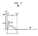
- Fig. 3 illustrates an exemplary diagram of a transmitted impulse signal and a resultant impulse response;
- Fig. 4 is a block diagram of an exemplary receiver;
- Fig. 5 is a block diagram of an exemplary equalizer; and
- Fig. 6 illustrates a mapping of DFE model coefficients to ADDFSE coefficients and metric weights; and
- Fig. 7 is a flowchart outlining an exemplary operation of an equalization technique.
-
- The DDFSE equalizer provides a powerful architecture to mitigate the effects of noise, ISI and CCI. Unfortunately, previous techniques to generate coefficients and metric weights for DDFSEs have proved difficult, the resulting DDFSEs did not work well and the resulting DDFSEs could not accommodate multiple antennas. Because equalizers can generally benefit from multiple antennas, including mitigating the effects of Rayleigh fading and interference, previous DDFSE equalizers were limited in their practical applications.
- This invention provides an advanced DDFSE (ADDFSE) that expands traditional DDFSEs to utilize more than one antenna and respective front-end filter. The ADDFSE coefficients and metric weights are easily generated based on a DFE model. The ADDFSE significantly improves equalizer performance over traditional DDFSEs by providing better weights. The following description in connection with Figures 1-5 provides a general background discussion of data transmission environments in relation to equalizers.
- Figure 1 shows an exemplary block diagram of a
digital transmission system 100. Thesystem 100 includes adigital transmitter 110, atransmission medium 120 and adigital receiver 150. Thedigital transmitter 110 can be any one of a number of different sources such as a wireless transmitter, a transmission system employing wires such as a twisted wire pair, a transmitter adapted for transmitting across coaxial cable, an optical transmitter, a fiber-optic transmitter, a sonic transmitter or any other known or later developed device suitable for transmitting digital symbol information. - The
digital transmitter 110 can transmit a signal containing digital symbol information, i.e., the desired signal, through thetransmission medium 120 vialink 112 and thetransmission medium 120 can provide filtered digital symbol information to thedigital receiver 150 vialink 152. - The
links transmitter 110 to thetransmission medium 120 and to thereceiver 150 respectively. - As an example, the
digital transmission medium 120 may have aresponse filter 122, aco-channel interference source 140 andco-channel filter 146, anoise generator 130 and asumming junction 128. Theresponse filter 122 can receive the digital symbol information from thedigital transmitter 110 via thelink 122 and can provide filtered digital symbol information to thesumming junction 128 via thelink 126. As the digital symbol information transmitted by thedigital transmitter 110 propagates through thetransmission medium 120, the signal is distorted according to the characteristics of thetransmission medium 120. - For example, concurrent with the digital symbol information transmission, the
noise generator 130 generates noise and theco-channel interference source 140 generates one or more second signals that are filtered by theco-channel filter 146. Both the above noise and interference signals are added to the filtered digital symbol information at thesumming junction 128 which then provides the sum to thedigital receiver 150 via thelink 152. - The
response filter 122 can be any combination of filters that results due to any naturally occurring or artificial physical characteristics of thetransmission medium 120 that can receive a signal from thedigital transmitter 100 and provide a filtered signal to thereceiver 150. Thenoise generator 130 can be any combination of sources capable of generating noise including average white Gaussian noise (AWGN), and theco-channel interference source 140 andfilter 146 can be any number of systems or sources that can produce co-channel interference in thereceiver 150. Thesumming junction 128 can be any device or element capable of receiving various signals and noise sources, combine the signals and noise, and provide the signals and noise to adigital receiver 150. Thedigital receiver 150 can be any one of a number of different receivers such as a wireless receiver, a reception system employing wires such as a twisted wire pair, a receiver adapted to receive signals from a coaxial cable, an optical receiver, a fiber optic receiver, a sonic receiver or any other known or later developed device suitable for receiving digital symbol information. - Fig. 2 is an exemplary block diagram of a wireless
digital transmission system 200 for transmitting signals with digital symbol information. The wirelessdigital transmission system 200 includes adigital transmitter 110 with atransmitter antenna 114, adigital receiver 150 with areceiver antenna 154, anoise generator 130, aco-channel interference source 140 with aco-channel antenna 144 and astructure 220 capable of reflecting wireless radio signals. - The digital symbol information is transmitted from the
digital transmitter 110 to thedigital receiver 150 usingantennas digital transmitter 110 can reach thedigital receiver 150 through a variety of paths. In Fig. 2, the digital symbol information reaches thedigital receiver 150 directly through afirst path 210 and also indirectly through asecond path 212, athird path 214 and afourth path 216 that are formed by reflections from thestructure 220. Thedigital receiver 150 further receives noise from thenoise generator 130 and signals from theco-channel source 140 via thepath 240. While Fig. 2 depicts thedigital receiver 150 as having a single antenna, it should be appreciated that thedigital receiver 150 can alternatively have multiple antennas. - Fig. 3 shows a diagram of an
impulse signal 310 and resultingimpulse response 320 of a transmission medium on a chart having anamplitude axis 302 and atime axis 304. Theimpulse response 320 is generated by the filtering characteristics of the transmission medium as theimpulse signal 310 is transmitted by a transmitter and propagates through the transmission medium. Theimpulse response 320 can be described by equation (1):where c(t-τk) is the shaping pulse of the system, γk is the complex amplitude of the k-th path of the transmitted signal, and τk is the delay of the k-th path. Usually, γk is a complex Gaussian random variable and is independent for the different paths. As shown in Fig. 3, the
impulse response 320 is delayed from theimpulse signal 310 by a time delay τ1. The impulse response time Δτir = τ2-τ1 of thetransmission medium 120 is the absolute difference between the start of the impulse response, τ1, and the time at which theimpulse response 320 effectively ends, τ2. - Various performance obstacles arise such as Rayleigh fading and inter-symbol interference (ISI) can occur because a transmitted signal may travel along a number of different paths to a receiver. When the differences in path lengths are relatively small, multiple signal images appear at the receiver at almost the same time and performance is essentially unaffected. As the differences in path lengths increase, the multiple signal images can destructively interfere with each other, thus giving rise to Rayleigh fading.
- As the differences in path lengths further increase, the received signal becomes dispersed over an extensive time period and can appear as echoes of the same signal. Inter-symbol interference (ISI) generally occurs when the two or more symbols are generated in a time span less than the impulse response time Δτir of a
transmission medium 120. To mitigate the effects of ISI, an equalization technique can be used to resolve the various symbols received at any given time. However, for any equalization technique to produce the most accurate symbol estimation in a signal having ISI, the technique must have a response time greater than or equal to the impulse response time Δτir of the received signal. - The response time of an equalizer is the amount of time samples the equalizer acts on at any given moment. For example, an equalization system sampling an input signal once every microsecond and capable of simultaneously processing one hundred samples has a response time of one hundred microseconds. If the response time of an equalizer is less than the impulse response time of the received signal, the equalizer cannot perform as well as a comparable equalizer with a longer response time. Furthermore, as the response time of an equalizer is shortened, performance will decrease accordingly.
- Unfortunately, the complexity of equalizers increases with an increasing length of the equalizer's response time. As a result, it may be impractical or impossible for a given equalizer to process a received signal if the equalizer must incorporate the entire impulse response of the received signal. This is especially true for pure MLSE equalizers where computational complexity increases exponentially with each added tap-delay. For a receiver having limited resources, the MLSE equalization techniques often must truncate the impulse response of the received signal more than competing techniques, thus leading to inferior performance as compared to other equalizers such as the ADDFSE.
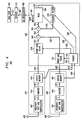
- Fig. 4 shows an exemplary block diagram of a
receiver 150 that includes ADDFSE. The receiver includes twoantennas ends ADDFSE equalizer 500, a de-interleaver 600, a decoder 590 and adata sink 600. The firstfront end 410 has a first frequency shifter/demodulator 412, afirst sampler 414 and afirst buffer memory 416. Likewise, the second front-end 420 has a second frequency shifter/demodulator 422, asecond sampler 424 and asecond buffer memory 426. Theequalizer 500 includes a first front-end filter 510, a second front-end filter 520, atrainer 530, a first summingjunction 540, a second summingjunction 554, anMLSE 560 and afeedback filter 570. - The
receiver 150 receives signals having digital symbol information via theantennas ends ends equalizer 500. Theequalizer 500 extracts symbols and passes the extracted symbols to thede-interleaving device 600 which passes de-interleaved symbols to thedecoder 610 which, in turn, provides decoded symbols to the data sink 620. - The received signal may be an iso-synchronous burst such as a Time Division Multiple Access (TDMA) burst with an 8-PSK modulation, asynchronous burst, a continuous signal or any other communication scheme. Furthermore, the signal can be modulated according to a QPSK, FSK or any other known or later developed modulation scheme. For the discussion below, it is assumed that the received signal is an iso-synchronous burst (or signal burst). It is further assumed that each
antenna - Each exemplary signal burst can contain any number of payload symbols along with a number of training symbols and guard symbols. Payload symbols are symbols containing the data to be transmitted. Training symbols are predetermined symbols placed at known positions within the signal that enable an
equalizer 500 to better adapt its various systems to more accurately estimate the payload symbols. For the following discussion, it is assumed that each signal burst contains at least 26 sequential training symbols located near the middle of the burst. However, it should be appreciated that the training symbols can be arranged and disbursed anywhere within the signal burst according to any known or later developed scheme. Guard symbols are symbols that pad either or both of the beginning and end of the burst and can be used for a variety of purposes, including providing buffering, timing and synchronization. - Both
antennas ends demodulators ends samplers links samplers memories links buffer memories trainer 530 via thelinks end filters links - The
trainer 530 receives the digitized signals via thelinks equalizer 500 as if it were a DFE with F feed-forward taps per branch and B feedback taps, using MMSE criterion. This training approach is based on the assumption that the weights for an MLSE equalizer can be approximated by the weights of a DFE according to equation (2), i.e.,end filters MLSE 560 and thefeedback filter 570. Proof of equation (1) can be found in Ariyavisitakul, S., Winters, J. and Sollenberger, N., "Joint Equalization And Interference Suppression For High Data Rate Wireless Systems", 1999 IEEE 49th Vehicular Technology Conference (May 16-20 1999), incorporated herein by reference in its entirety. - The
trainer 530 determines the various feed-forward and feedback weights by applying a recursive least squares (RLS) technique using the training symbols in the digitized signal; however, any technique now known or later developed capable of determining the various coefficients for a DFE can also be used. - For an ADDFSE having F number of tap-delays in each of its front-
end filters MLSE 560 and (B-µ) number of tap-delays in itsfeedback filter 570, thetrainer 530 generates a DFE mathematical model having feed-forward filters with F taps (f1, f2,...fF) and a feedback filter with B taps (b1, b2....bµ, bµ+1, bµ+1,...bB). Next, the F coefficients for the ADDFSE front-end filters are assigned the F feed-forward coefficients of the DFE model (f1, f2,...fF) and the (B-µ) coefficients for the ADDFSE feedback filter are assigned the last (B-µ) feedback coefficients of the DFE model (bµ+1, bµ+1,...bB). Finally, the MLSE metric weights are generated using the first µ feedback coefficients of the DFE model (b1, b2....bµ). - After the various weights and coefficients are determined, the
trainer 530 applies them to the front-end filters links MLSE 560 usinglink 536 and thefeedback filter 570 usinglink 538. Once received, the various coefficients and metric weights can be held constant as the digitized signal is passed from thebuffer memories end filters equalizer 500. However, it should be appreciated that some or all of the coefficients and metric weights can alternatively be updated as required by design choice. - After the
various equalizer components end filters ends junction 540. The exemplary front-end filters end filters links end filters - To use T-spaced taps, the
exemplary equalizer 500 can employ a timing recovery technique (not shown) that is optimum for a DFE with a single feed-forward tap, as described in detail in Ariyavisitakul, S.L. and Li, Y.(G.), "Joint coding and decision feedback equalization for broadband wireless channels," IEEE Journal of Selected Areas in Communications, Vol. 15, pp. 5-15, January 1997 and Ariyavisitakul, "Intelligent recovery for a broadband adaptive equalizer" (U.S. Patent Number 5,809,086), both herein incorporated by reference in their entirety. However, it should be appreciated that any presently known or later developed timing recovery technique alternatively can be used. - The filtered signals are received by the first summing
junction 540 via thelinks junction 554 via thelink 542 and is then added to a feedback signal fromlink 572 to produce a second sum. While theexemplary equalizer 500 depicts two summingjunctions 550 and 554, it should be appreciated that the summingjunctions 550 and 554 can alternatively be combined to produce a single summing junction. - The
MLSE 560 receives the second sum from the second summingjunction 554 via thelink 556 and performs MLSE equalization on the sum to produce hard decisions atlink 562 and soft decisions atlink 564. While theexemplary MLSE 560 uses a Viterbi technique to perform the MLSE operation, it should be appreciated that any combination of techniques now known or later developed that can implement an MLSE alternatively can be used. Theexemplary MLSE 560 has a memory of µ taps where µ is a positive integer and an appropriate span as required according to the design parameters of theequalizer 500. - Hard decisions are decisions generated by passing a received signal through the MLSE to produce a received vector, quantizing the components of the received vector against predetermined thresholds, then finding the closest resulting vector in the Hamming sense. The
feedback filter 570 can receive hard decision data via thelink 562 and perform feedback filtering based on the hard decision data to produce feedback data, which is provided to the second summingjunction 554 via thelink 572. Theexemplary feedback filter 570 includes (B-µ) taps with each tap providing a weighted output. As digital values pass from tap to tap, each tap output is multiplied by a respective coefficient. The weighted outputs are then added to provide the filtered output atlink 572 which is fed to the second summingjunction 554. TheMLSE 560 andfeedback filter 570 work together to mitigate ISI and noise present in the received signal. - Soft decision decoding, like hard decision decoding, involves passing the received signal through the MLSE to produce a received vector. However, unlike hard decisions, soft decisions are generally determined by finding the closest point in the receiver's constellation against the received vector in the Euclidean distance sense, rather than the Hamming sense. While both soft decisions and hard decisions are estimates of the symbols in the received symbol streams, soft decisions contain additional information on the accuracy of the symbol estimates that can be used by an equalizer. As mentioned above, the
MLSE 560 generates soft output decisions that can be provided to the de-interleaver 600 via thelink 564. The soft output decisions are generated using Lee's method as described in Lee, L.N., "Real-time minimal-bit-error probability decoding of convolutional codes," IEEE Transactions on Communications, Vol. 22, pp. 146-151, (February 1974), herein incorporated by reference in it entirety. However, it should be appreciated that any technique now known or later developed that can produce soft output decisions from an MLSE device can alternatively be used. - The de-interleaver 600 receives the soft outputs, reorders the soft outputs according to a predetermined interleaved order of the received signal and provides the reordered symbols to the
decoder 610 via thelink 602. Thedecoder 610 receives the reordered data, performs error correction and decoding using convolutional decoding based on a Viterbi technique. While theexemplary decoder 610 uses a Viterbi technique to perform convolutional decoding, it should be appreciated that any presently known or later developed technique capable of performing convolutional decoding can alternatively be used. Furthermore, thedecoder 610 can alternatively perform block-error correction, Turbo-error correction or any other presently known or later developed error correction scheme. - The data sink 620 receives data from the
decoder 610 via thelink 612. The data sink 620 can be any device capable of receiving data such as an electronic circuit capable of transforming the data to an acoustic format or a computer with a storage system. However, it should be appreciated that the data sink 620 can be any combination of hardware and software capable of receiving, relaying, storing, sensing or perceiving data provided by thedecoder 610. - While the
exemplary receiver 150 has twoantennas ends end filters end filters end filter end filter - Additionally, while the
exemplary receiver 150 receives symbolinformation using antennas ends end filters trainer 530. Such devices include electrical wires, optical links, a direct serial/parallel cable connections, a connection over a wide area network or local area network, a connection over an intranet or an extranet, a connection over the Internet, or a connection over any other distributed processing network or system. Additionally,antennas ends end filters trainer 530 can be used. - Fig. 5 shows a block diagram of an exemplary equalizer 700 with a
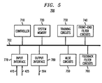
controller 710, asystem memory 720,training circuits 730, front-end filter circuits 740,MLSE circuits 750,feedback filter circuits 760, aninput interface 770 and anoutput interface 780. Thecontroller 710 interfaces with the other components 720-780 using a control/data bus 702. - Under control of the
controller 710, theinput interface 770 can receive two streams of digital symbol information via thelinks input device 770 receives two streams of digital symbol information, theinput device 770 can alternatively receive any number of streams of digital symbol information as required by design choice. Furthermore, while theinput device 770 receives bursts of digital symbol information, theinput device 770 can alternatively receive continuous streams of digital symbol information or any hybrid of continuous or burst streams of digital symbol information. - The
input interface 770 can receive digital symbol information from any device such as a wireless receiver, analog to digital converter, disc drive, UART, LAN, WAN, parallel digital interface, serial digital interface, software interface or any combination of software and hardware in any form now known or later developed. For the following discussion, the input interface receives data from a wireless receiver using an analog to digital converter that converts the analog signals to digital form. Once thecontroller 710 imports the digital symbol information, thecontroller 710 stores the data in thesystem memory 720. - The
controller 710 then copies each digitized stream of digital symbol information from thesystem memory 720 to thetraining circuits 730. Thetraining circuits 730 then determine the various coefficients and metric weights of the front-end filter circuits 740, theMLSE circuits 750 and thefeedback circuits 760 using the digital symbol information based on a DFE model. For an ADDFSE having F number of tap-delays in each of its front-end filters, µ number of taps in its MLSE and (B-µ) number of tap-delays in its feedback filter, the training circuits generate a DFE mathematical model having feed-forward filters with F taps (f1, f2,...fF) and a feedback filter with B taps (b1, b2....bµ, bµ+1, bµ+1,...bB). - After the various coefficients and metric weights are generated, the
controller 710 copies the F feed-forward coefficients (f1, f2,...fF) to the front-end filter circuits 740. Thecontroller 710 further copies the last (B-µ) feedback coefficients (bµ+1, bµ+1,...bB) to thefeedback filter circuits 760 and copies the MLSE metric weights, which can be based on the first µ feedback coefficients (b1, b2....bµ), to theMLSE circuits 750. - The
controller 710 then transfers the received streams of digital symbol information to the front-end filter circuits 740. The front-end filter circuits 740 then process each received stream to generate filtered signals, which can provide interference suppression. - As the filtered signal streams are generated, the
controller 710 adds the filtered signal streams to each other along with a stream of feedback data produced by thefeedback circuits 760, and transfers the summed streams to theMLSE circuits 750. - The
MLSE circuits 750 receive the summed streams and perform MLSE equalization on the summed streams to produce streams of both hard decisions and soft decisions. Thecontroller 710 then transfers the hard decision stream to thefeedback circuits 760, which performs feedback filtering on the hard decisions to produce a stream of feedback data. As feedback data is produced, thecontroller 710 adds the feedback data to the filtered signals produced by the front-end filter circuits 740 and fed back to theMLSE circuits 750. TheMLSE circuits 750 andfeedback filter circuits 760 work together to mitigate ISI and noise present in the received signal streams. - As mentioned above, the
MLSE circuits 750 produce soft decisions, which are estimates of the accuracy of the symbols in the received symbol streams, as well as hard decisions. As the soft decisions in the soft decision stream are produced, thecontroller 710 can transfer the soft decisions to theoutput interface 780, which then exports the softdecisions using link 564. Theoutput interface 780 can export the soft decisions in any digital form or any information form that can represent symbols. Like theinput interface 770, theoutput interface 780 should not be construed to refer exclusively to hardware, but can be any known or later discovered combination of hardware and software routines capable of communicating or storing data. - Fig. 6 illustrates the assignment of coefficients and metric weights for an ADDFSE based on a DFE model. The illustration shows a
trainer 800 having aDFE model 810 and a coefficient-to-weight converter 840 and further shows anADDFSE 900 having a first front-end filter 910, a second front-end filter 920, anMLSE 930 and afeedback filter 940. For the purpose of this discussion, the ADDFSE has F number of tap-delays in each of its front-end filters MLSE 930 and (B-µ) number of tap-delays in itsfeedback filter 940. - As the
trainer 800 receives a burst of data containing training symbols (not shown), thetrainer 800 generates the feed-forward coefficients 820 and thefeedback coefficients 830 for theDFE model 810. TheDFE model 810 has F feed-forward coefficients 820 (f1, f2,...fF) and B feedback coefficients 830 (b1, b2... bB) which can be divided into a first feedback group (b1, b2....bµ) 832 and a second feedback group (bµ+1, bµ+1,...bB) 834. - The F feed-
forward coefficients 820 are assigned to the front-end coefficients end filters first feedback group 832 is transformed by the coefficient-to-metric-weight converter 840 to a series of metric weights based on the design parameters, i.e., number of taps and span, of the ADDFSE. The metric weights are then assigned to the MLSEmetric weights 932 of theMLSE 930. Furthermore, thesecond feedback group 834 is assigned to thefeedback coefficients 942 of thefeedback filter 940. - Fig. 7 illustrates a flowchart outlining an exemplary operation of a symbol estimation technique for an equalizer having one or more front-ends, an MLSE device and a feedback filter. In
step 1010, a signal containing a symbol stream is received and stored. While the exemplary technique independently receives a signal using two antennas with associated electronics, it should be appreciated that the received signal can be separately received by any number of antennas with associated front-end electronics. The exemplary received symbol streams consist of finite bursts of symbols including payload symbols, training symbols and guard symbols. However, it should be appreciated that the received symbols can alternatively be derived from a continuous stream of symbols. The operation continues to step 1020. - In
step 1020, the training symbols received instep 1010 are used to determine the coefficients and metric weights of various devices associated with the equalizer, including the one or more front-end filters, an MLSE device and a feedback filter. For a receiver having one or more front-end filters, each with F taps and respective coefficients, an MLSE device having µ taps and respective metric weights and a feedback filter with (B-µ) taps and respective coefficients, the equalizer can be trained as if it were a DFE with F feed-forward taps per branch and B feedback taps, using MMSE criterion. - The exemplary training technique determines the various feed-forward and feedback weights by applying a recursive least squares (RLS) technique using the training symbols in the symbol stream; however, it should be appreciated that any now known or later developed technique that can determine the various coefficients for a DFE alternatively can be used. The operation continues to step 1030.
- In
step 1030, the F coefficients of the front-end filters can be assigned the F feed-forward tap values of the DFE model. Furthermore, the first µ feedback coefficient (b1, b2,...bµ) of the DFE model can be used to compute the metrics of the MLSE and the remaining coefficients (bµ+1, ...b B ) can be assigned to the feedback filter. The operation continues to step 1040. - In
step 1040, the coefficients and metric weights determined insteps - In
step 1050, the received symbol stream is processed using the coefficients and metrics assigned instep 1040. Processing begins by providing the received symbol stream to the front-end filters. The front-end filters can process the received symbol stream to mitigate the effects of CCI. The outputs of the front-end filters are then added and provided to the MLSE device and feedback filter which can mitigate the effects of noise and ISI. As the symbol stream is processed, the MLSE device can provide both soft output decisions in addition to hard decisions, which are provided to the feedback filter. Next, instep 1060, the soft output decisions, or symbol estimates, are de-interleaved. Then, instep 1070, the de-interleaved symbol estimates are decoded. Finally, instep 1080, the decoded symbol estimates are exported and the operation stops instep 1090. - As shown in Figs. 4 and 5, the systems and methods of this invention are preferably implemented on a digital signal processor (DSP) or other integrated circuits. However, the systems and methods can also be implemented using any combination of one or more general purpose computers, special purpose computers, programmed microprocessors or microcontrollers and peripheral integrated circuit elements, hardware electronic or logic circuits such as Application Specific Integrated Circuits (ASIC), discrete element circuits, programmable logic devices such as a PLD, PLA, FPGA, or PAL, or the like. In general, any device on which exists a finite state machine capable of implementing the various elements of Figs. 4 and 5 and the flowchart of Fig. 7 can be used to implement the
equalizer 500 functions. - It should also be understood that each of the circuits shown in Figs. 4 and 5 can be implemented as portions of a suitably programmed digital signal processor. Alternatively, each of the circuits shown in Fig. 4 can be implemented as physically distinct hardware circuits within a micro-controller or microcomputer, or using an ASIC, a FPGA, a PDL, a PLA, or a PAL, or discrete logic elements or discrete circuit elements. The particular form that each circuit shown in Figs. 4 and 5 will take is a design choice and will be obvious and predictable to those skilled in the art.
- While this invention has been described in conjunction with the specific embodiments thereof, it is evident that many alternatives, modifications, and variations will be apparent to those skilled in the art. Accordingly, preferred embodiments of the invention as set forth herein are intended to be illustrative, not limiting. There are changes that may be made without departing from the spirit and scope of the invention.
Claims (20)
- A method for extracting symbols from a received signal containing symbol information using an ADDFSE equalizer having one or more front-end filters, an MLSE device and a feedback filter, comprising:receiving the received signal;generating at least one or more coefficients or metric weights for at least one of the one or more front-end filters, the MLSE device and the feedback filter based on a DFE model and the received signal; andextracting symbols from the received signal based on at least the one or more coefficients or metric weights.
- The method of claim 1, wherein the step of generating includes generating at least one or more coefficients for the one or more front-end filters.
- The method of claim 1, wherein the step of generating includes generating at least one or more coefficients for the feedback filter.
- The method of claim 1, wherein the step of generating includes generating at least one or more metric weights for MLSE device.
- The method of claim 1, further comprising extracting soft decisions from the MLSE device.
- The method of claim 5, further comprising deinterleaving the soft decisions to produce deinterleaved data.
- The method of claim 6, further comprising decoding the deinterleaved data.
- A method for generating the coefficients in an ADDFSE equalizer having one or more front-end filters, an MLSE device and a feedback filter, comprising:receiving a received signal; andgenerating at least one or more coefficients or metric weights for at least one of the one or more front-end filters, the MLSE device and the feedback filter based on a DFE model and the received signal.
- The method of claim 8, wherein the step of generating includes generating at least one coefficient for the one or more front-end filters.
- The method of claim 8, wherein the step of generating includes generating at least one coefficient for the feedback filter.
- The method of claim 8, wherein the step of generating includes generating at least one metric weight for the MLSE device.
- The method of claim 8, wherein the step of generating uses one or more training symbols contained in the received signal.
- A symbol estimation device that extracts symbols from a received signal containing symbol information, comprising:wherein symbols are extracted from the MLSE based on at least one of the one or more first filtered signals.one or more front-end filters that receive the received signal and provide one or more first filtered signals, wherein the one or more front-end filters include one or more coefficients based on a DFE model;an MLSE device that produces a second filtered signal based on the one or more first filtered signals; anda feedback filter that receives the second filtered signal to produce a third filtered signal that is fed to the MLSE device;
- The device of claim 13, wherein the MLSE device contains at least one metric weight based on the DFE model.
- The device of claim 13, wherein the feedback filter contains at least one coefficient based on the DFE model.
- A symbol estimation device that extracts symbols from a received signal containing symbol information, comprising:wherein symbols are extracted from the MLSE based on at least the two or more first filtered signals.two or more front-end filters that receive the received signal and provide two or more first filtered signals;an MLSE device that produces a second filtered signal based on at least the two or more first filtered signals; anda feedback filter that receives the second filtered signal to produce a third filtered signal that is fed to the MLSE device;
- The device of claim 16, wherein one or more coefficients or metric weights for at least one of the one or more front-end filters, the MLSE device and the feedback filter are based on a DFE model.
- The device of claim 16, wherein the two or more front-end filters contain at least one coefficient based on a DFE model.
- The device of claim 16, wherein the feedback filter contains at least one coefficient based on a DFE model.
- The device of claim 16, wherein the MLSE device contains at least one metric weight based on a DFE model.
Applications Claiming Priority (2)
| Application Number | Priority Date | Filing Date | Title |
|---|---|---|---|
| US76668801A | 2001-01-22 | 2001-01-22 | |
| US766688 | 2001-01-22 |
Publications (2)
| Publication Number | Publication Date |
|---|---|
| EP1229697A2 true EP1229697A2 (en) | 2002-08-07 |
| EP1229697A3 EP1229697A3 (en) | 2002-08-14 |
Family
ID=25077204
Family Applications (1)
| Application Number | Title | Priority Date | Filing Date |
|---|---|---|---|
| EP02100009A Withdrawn EP1229697A3 (en) | 2001-01-22 | 2002-01-14 | Weight-coefficients generation technique for DDFSE equaliser |
Country Status (2)
| Country | Link |
|---|---|
| EP (1) | EP1229697A3 (en) |
| CA (1) | CA2366075A1 (en) |
Cited By (3)
| Publication number | Priority date | Publication date | Assignee | Title |
|---|---|---|---|---|
| US6970524B1 (en) | 1999-12-06 | 2005-11-29 | At&T Corp. | Methods and systems for symbol timing recovery |
| US7340016B2 (en) | 2001-05-11 | 2008-03-04 | Telefonaktiebolaget Lm Ericsson (Publ) | Equalizers for multi-branch receiver |
| JP2009268107A (en) * | 2008-04-28 | 2009-11-12 | Nec Electronics Corp | Delayed decision feedback sequence estimator and method |
-
2001
- 2001-12-21 CA CA 2366075 patent/CA2366075A1/en not_active Abandoned
-
2002
- 2002-01-14 EP EP02100009A patent/EP1229697A3/en not_active Withdrawn
Non-Patent Citations (3)
| Title |
|---|
| ARIYAVISITAKUL S L ET AL: "JOINT EQUALIZATION AND INTERFERENCE SUPPRESSION FOR HIGH DATA RATE WIRELESS SYSTEMS" IEEE JOURNAL ON SELECTED AREAS IN COMMUNICATIONS, IEEE INC. NEW YORK, US, vol. 18, no. 7, July 2000 (2000-07), pages 1214-1219, XP000950218 ISSN: 0733-8716 * |
| ARIYAVISTAKUL S ET AL: "Joint equalization and interference suppression for high data rate wireless systems" VEHICULAR TECHNOLOGY CONFERENCE, 1999 IEEE 49TH HOUSTON, TX, USA 16-20 MAY 1999, PISCATAWAY, NJ, USA,IEEE, US, 16 May 1999 (1999-05-16), pages 700-706, XP010341874 ISBN: 0-7803-5565-2 * |
| ZENG H H ET AL: "A 2-stage soft-output equalizer for EDGE" 2000 IEEE WIRELESS COMMUNICATIONS AND NETWORKING CONFERENCE. CONFERENCE RECORD (CAT. NO.00TH8540), PROCEEDINGS OF IEEE CONFERENCE ON WIRELESS COMMUNICATIONS AND NETWORKING, CHICAGO, IL, USA, 23-28 SEPT. 2000, pages 393-397 vol.1, XP002201896 2000, Piscataway, NJ, USA, IEEE, USA ISBN: 0-7803-6596-8 * |
Cited By (3)
| Publication number | Priority date | Publication date | Assignee | Title |
|---|---|---|---|---|
| US6970524B1 (en) | 1999-12-06 | 2005-11-29 | At&T Corp. | Methods and systems for symbol timing recovery |
| US7340016B2 (en) | 2001-05-11 | 2008-03-04 | Telefonaktiebolaget Lm Ericsson (Publ) | Equalizers for multi-branch receiver |
| JP2009268107A (en) * | 2008-04-28 | 2009-11-12 | Nec Electronics Corp | Delayed decision feedback sequence estimator and method |
Also Published As
| Publication number | Publication date |
|---|---|
| EP1229697A3 (en) | 2002-08-14 |
| CA2366075A1 (en) | 2002-07-22 |
Similar Documents
| Publication | Publication Date | Title |
|---|---|---|
| Belfiore et al. | Decision feedback equalization | |
| US5903610A (en) | Method and apparatus for channel estimation | |
| US5809086A (en) | Intelligent timing recovery for a broadband adaptive equalizer | |
| US7190744B2 (en) | Error generation for adaptive equalizer | |
| CA2219393C (en) | Tap selectable decision feedback equalizer | |
| EP1058406A2 (en) | Method and apparatus for reducing the computational complexity and relaxing the critical path of reduced state sequence estimation (RSSE) techniques | |
| JP2008532354A (en) | Wireless communication apparatus and associated method for providing improved block equalization | |
| US7215719B2 (en) | Method for demodulating a digital signal based on an estimate of a symbol of the digital signal, and an associated receiver | |
| KR101085708B1 (en) | Equalizers for multi-branch receiver | |
| EP1016251B1 (en) | Method and arrangement for demodulating data symbols | |
| JPH11508114A (en) | Equalizer with reduced state sequence estimation method for digital transmission equipment receiver. | |
| US6707850B1 (en) | Decision-feedback equalizer with maximum-likelihood sequence estimation and associated methods | |
| US7292661B1 (en) | Block-iterative equalizers for digital communication system | |
| US6724841B2 (en) | Equalizer with a cost function taking into account noise energy | |
| US20020054655A1 (en) | Method and apparatus for reducing multipath distortion in a wirless LAN system | |
| EP1229697A2 (en) | Weight-coefficients generation technique for DDFSE equaliser | |
| EP1380144B1 (en) | Method and system for minimum mean square error equalization (mmse) iteratively circulating short training sequences until mse falls below a target threshold | |
| US6301315B1 (en) | Methods and systems for symbol estimation in a receiver | |
| US20070160010A1 (en) | Method and apparatus to perform channel estimation for a communication system | |
| Hart et al. | Innovations-based MAP detection for time-varying frequency-selective channels | |
| US7248849B1 (en) | Frequency domain training of prefilters for receivers | |
| CN106487400A (en) | Uncoupling single antenna Interference Suppression System based on fractionally spaced equalizer and method | |
| EP1156634A1 (en) | Sequence estimator and equaliser | |
| JP2600970B2 (en) | Diversity receiver | |
| EP1128617A1 (en) | Method and receiver for obtaining channel estimated values for equalising digital signals |
Legal Events
| Date | Code | Title | Description |
|---|---|---|---|
| PUAI | Public reference made under article 153(3) epc to a published international application that has entered the european phase |
Free format text: ORIGINAL CODE: 0009012 |
|
| PUAL | Search report despatched |
Free format text: ORIGINAL CODE: 0009013 |
|
| AK | Designated contracting states |
Kind code of ref document: A2 Designated state(s): AT BE CH CY DE DK ES FI FR GB GR IE IT LI LU MC NL PT SE TR |
|
| AX | Request for extension of the european patent |
Free format text: AL;LT;LV;MK;RO;SI |
|
| AK | Designated contracting states |
Kind code of ref document: A3 Designated state(s): AT BE CH CY DE DK ES FI FR GB GR IE IT LI LU MC NL PT SE TR |
|
| AX | Request for extension of the european patent |
Free format text: AL;LT;LV;MK;RO;SI |
|
| 17P | Request for examination filed |
Effective date: 20020925 |
|
| 17Q | First examination report despatched |
Effective date: 20021120 |
|
| AKX | Designation fees paid |
Designated state(s): DE FR GB |
|
| STAA | Information on the status of an ep patent application or granted ep patent |
Free format text: STATUS: THE APPLICATION IS DEEMED TO BE WITHDRAWN |
|
| 18D | Application deemed to be withdrawn |
Effective date: 20030401 |