EP1229557A1 - Ribbed suspension insulator - Google Patents
Ribbed suspension insulator Download PDFInfo
- Publication number
- EP1229557A1 EP1229557A1 EP00957069A EP00957069A EP1229557A1 EP 1229557 A1 EP1229557 A1 EP 1229557A1 EP 00957069 A EP00957069 A EP 00957069A EP 00957069 A EP00957069 A EP 00957069A EP 1229557 A1 EP1229557 A1 EP 1229557A1
- Authority
- EP
- European Patent Office
- Prior art keywords
- shed
- pollution
- insulator
- suspension insulator
- sheds
- Prior art date
- Legal status (The legal status is an assumption and is not a legal conclusion. Google has not performed a legal analysis and makes no representation as to the accuracy of the status listed.)
- Withdrawn
Links
- 239000012212 insulator Substances 0.000 title claims description 50
- 239000000725 suspension Substances 0.000 title claims description 24
- 239000000463 material Substances 0.000 claims abstract description 32
- 230000003247 decreasing effect Effects 0.000 claims description 2
- 230000000694 effects Effects 0.000 description 7
- XLYOFNOQVPJJNP-UHFFFAOYSA-N water Substances O XLYOFNOQVPJJNP-UHFFFAOYSA-N 0.000 description 6
- 238000002474 experimental method Methods 0.000 description 5
- 238000005406 washing Methods 0.000 description 5
- 239000000843 powder Substances 0.000 description 3
- FAPWRFPIFSIZLT-UHFFFAOYSA-M Sodium chloride Chemical compound [Na+].[Cl-] FAPWRFPIFSIZLT-UHFFFAOYSA-M 0.000 description 2
- 239000004568 cement Substances 0.000 description 2
- 239000005995 Aluminium silicate Substances 0.000 description 1
- 235000012211 aluminium silicate Nutrition 0.000 description 1
- 238000001035 drying Methods 0.000 description 1
- 238000010981 drying operation Methods 0.000 description 1
- 239000000428 dust Substances 0.000 description 1
- 239000010419 fine particle Substances 0.000 description 1
- 239000012774 insulation material Substances 0.000 description 1
- NLYAJNPCOHFWQQ-UHFFFAOYSA-N kaolin Chemical compound O.O.O=[Al]O[Si](=O)O[Si](=O)O[Al]=O NLYAJNPCOHFWQQ-UHFFFAOYSA-N 0.000 description 1
- 238000012423 maintenance Methods 0.000 description 1
- 239000000203 mixture Substances 0.000 description 1
- 230000002093 peripheral effect Effects 0.000 description 1
- 230000002265 prevention Effects 0.000 description 1
- 239000011780 sodium chloride Substances 0.000 description 1
- 238000005507 spraying Methods 0.000 description 1
Images


Classifications
-
- H—ELECTRICITY
- H01—ELECTRIC ELEMENTS
- H01B—CABLES; CONDUCTORS; INSULATORS; SELECTION OF MATERIALS FOR THEIR CONDUCTIVE, INSULATING OR DIELECTRIC PROPERTIES
- H01B17/00—Insulators or insulating bodies characterised by their form
- H01B17/02—Suspension insulators; Strain insulators
- H01B17/06—Fastening of insulator to support, to conductor, or to adjoining insulator
- H01B17/08—Fastening of insulator to support, to conductor, or to adjoining insulator by cap-and-bolt
-
- H—ELECTRICITY
- H01—ELECTRIC ELEMENTS
- H01B—CABLES; CONDUCTORS; INSULATORS; SELECTION OF MATERIALS FOR THEIR CONDUCTIVE, INSULATING OR DIELECTRIC PROPERTIES
- H01B17/00—Insulators or insulating bodies characterised by their form
- H01B17/02—Suspension insulators; Strain insulators
Definitions
- the present invention relates to an outer-rib type suspension insulator used preferably in an industrially heavy pollution area.
- a suspension insulator used under pollution environments it is general to use an anti-pollution type insulator in which a length of respective under-ribs is longer than that of a standard insulator, as shown in Fig. 6.
- the anti-pollution type insulator can make an under creepage distance longer since the length of respective under-ribs is long, thereby improving a voltage resistance.
- the anti-pollution type insulator mentioned above is widely used in our country (Japan).
- An object of the invention is to eliminate the drawbacks mentioned above and to provide a suspension insulator in which an accumulative amount of adhered pollution materials is low even if used in an industrially heavy pollution area and in which an excellent voltage resistance can be maintained for a long duration.
- an outer-rib type suspension insulator wherein an upper shed extending in a lateral direction is formed on a periphery of a head portion and a lower shed having a gradually spreading shape is formed from a halfway portion of the upper shed in such a manner that it curves outward, is characterized in that an upper surface of respective upper and lower sheds is inclined by 4 - 35°, thereby decreasing an accumulative amount of adhered pollution materials.
- it is preferred to set an inclination angle of the upper surface of the sheds to 5 - 20°.
- the lower shed having a gradually spreading shape is formed from a halfway portion of the upper shed in such a manner that it curves outward, an inner surface of thereof is smooth with no concavo-convex portions due to the under-ribs. Therefore, pollution materials such as suspended powder dusts are difficult to adhere accumulatively to the inner portion. Moreover, since respective sheds has a small inclination angle and a flat shape, the pollution materials are difficult to adhere to the sheds, and a washing effect due to rain is large. In addition, since a long creepage distance can be assured by the sheds, it is possible to maintain an excellent voltage resistance for a long duration even if used in an industrially heavy pollution area.
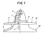
- Fig. 1 is an outer-rib type suspension insulator according to a first embodiment of the invention.
- a numeral 1 is a hollow head portion and a numeral 2 is an upper shed extending in a lateral direction, which is formed on a lower periphery of the head portion 1.
- an angle of an upper surface of the upper shed 2 i.e. an angle with respect to a horizontal surface in the case that a center axis of the insulator is assumed to be a perpendicular axis
- a lower shed 3 having a gradually spreading shape is formed from a halfway portion of a lower surface of the upper shed 2 in such a manner that it curves outward.
- an outer diameter of the lower shed 3 is the same as that of the upper shed 2 and is 320 mm.
- an angle of an upper surface of the lower shed 3 is 20°.
- a cap fitting 4 is connected to an outer portion of the head portion 1 via cement
- a clevis type pin fitting 5 is connected to an inner portion via cement.
- Fig. 2 is an outer-rib type suspension insulator according to a second embodiment of the invention.
- the upper shed 2 is the same as that of the first embodiment.
- an angle of the upper surface of the lower shed 3 is 25°.
- one intermediate shed 6 is formed between the upper shed 2 and the lower shed 3.
- An angle of an upper surface of the intermediate shed 6 is 15°, and an outer diameter of the intermediate shed 6 is slightly smaller than that of the upper shed 2 and the lower shed 3.
- Fig. 3 is an outer-rib suspension insulator according to a third embodiment of the invention.
- outer diameters of the intermediate shed 6 and the lower shed 3 are 320 mm, and an outer diameter of the upper shed 2 is slightly smaller than that of the intermediate shed 6 and the lower shed 3.
- An angle of the upper surface of the upper shed 2 is the same as that of the first embodiment, and an angle of the upper surface of the intermediate shed 6 is the same as that of the second embodiment.
- an angle of the upper surface of the lower shed 3 is 25°.
- Fig. 4 is an outer-rib type suspension insulator according to a fourth embodiment of the invention.
- two intermediate sheds 6 and 7 are formed between the upper shed 2 and the lower shed 3.
- all of the upper surface angles of the four sheds are 20°.
- a depression 8 is formed outside of the cap fitting 4. The depression 8 is filled with insulation materials so as not to store water therein.
- the sheds having a small angle with respect to a horizontal surface and a flat shape thrust outward at a side surface, and a long creepage distance is maintained so as to improve a voltage resistance.
- the flat sheds mentioned above since a wind is not stagnated between shed and shed, there is an effect for reducing an adhesion of the pollution materials supplied by wind as shown in the following experiments.
- these sheds thrust outward there is an advantage such that the pollution materials are easy to remove by a rainwater washing effect even if they are adhered.
- an inclination angle of the upper surface of respective sheds is set to 4 - 35° that is smaller than the known suspension insulator. If the inclination angle is not larger than 4°, a water drip performance becomes bad, and, if the inclination angle is not smaller than 35°, an adhesion prevention effect of the pollution materials is deteriorated.
- the upper surface inclination angle of respective sheds is set to 5 - 20°.
- insulator strings constructed by using the outer-rib type suspension insulator according to the invention shown in Fig. 3 third embodiment
- the standard insulator shown in Fig. 5 and the anti-pollution type insulator shown in Fig. 6 were set vertically in a test apparatus. Then, a cycle of spraying the pollution materials, supplying a fog, supplying a water and drying was repeated 4 times under the condition such that the insulator string was rotated slowly at 1 rpm.
- the pollution materials use was made of a mixture of NaCl and kaolin fine particles. The pollution materials were followed into the test apparatus for 20 minutes with a rate of 250 g/min. by means of a fan.
- a dust catcher was set in an opposite side of the test apparatus, and airflow with a wind speed of 3.5 m/s was caused in one direction in the test apparatus. Further, humidity was maintained under 70 %.
- the fog supplying operation was performed for 10 minutes, and the water supplying operation was performed for 5 minutes with an angle of 30° with respect to a horizontal line. This water supplying operation simulated a rainfall of 2 mm/min. After that, the drying operation was performed for 60 minutes. Then, an amount of adhered pollution materials on the lower surface of respective insulators was measured. As a result, a relative value, where an amount of adhered pollution materials of the anti-pollution type insulator was 100, was 156 in the standard insulator and was 12 in the outer-rib type suspension insulator according to the invention.
- a large amount of the pollution materials was adhered to a surface on the windward side of respective ribs as well as a front surface to which the wind blow was directly contacted.
- a large amount of the pollution materials was adhered to a surface on the windward side of respective ribs that are positioned at a back of the center portion as well as a front surface to which the wind blow was directly contacted.
- the outer-rib type suspension insulator of the invention since flat sheds having a small inclination angle are combined, it is possible to suppress an adhesion of the pollution materials on the lower surface. Therefore, if the outer-rib type suspension insulator according to the invention is used in the industrially heavy pollution area, an accumulative adhesion amount of the pollution materials is very few for a long duration as compared with the known anti-pollution type insulator. In addition, it is not necessary to perform a washing operation frequently as usual, and also it is possible to reduce a maintenance operation that takes a lot of time and effort.
Landscapes
- Insulators (AREA)
Abstract
Description
- The present invention relates to an outer-rib type suspension insulator used preferably in an industrially heavy pollution area.
- As a suspension insulator used under pollution environments, it is general to use an anti-pollution type insulator in which a length of respective under-ribs is longer than that of a standard insulator, as shown in Fig. 6. The anti-pollution type insulator can make an under creepage distance longer since the length of respective under-ribs is long, thereby improving a voltage resistance. The anti-pollution type insulator mentioned above is widely used in our country (Japan).
- Whereas, in the other industrially heavy pollution area of for example Asia, since a large amount of powder dusts are suspended in air, the powder dusts are easy to intrude into an inner portion of the ribs by wind and adhere to a surface of the rib. This phenomenon is different from our country. Therefore, even if the anti-pollution insulator is used in the other industrially heavy pollution area, a long rib of the anti-pollution type insulator has no effect, and an amount of adhered pollution materials is considerably increased in proportion to a long duration of service. In this manner, when the known anti-pollution type insulator is used in the other industrially heavy pollution area of for example Asia, it is necessary to repeat a washing operation frequently.
- An object of the invention is to eliminate the drawbacks mentioned above and to provide a suspension insulator in which an accumulative amount of adhered pollution materials is low even if used in an industrially heavy pollution area and in which an excellent voltage resistance can be maintained for a long duration.
- According to the invention, an outer-rib type suspension insulator, wherein an upper shed extending in a lateral direction is formed on a periphery of a head portion and a lower shed having a gradually spreading shape is formed from a halfway portion of the upper shed in such a manner that it curves outward, is characterized in that an upper surface of respective upper and lower sheds is inclined by 4 - 35°, thereby decreasing an accumulative amount of adhered pollution materials. In this embodiment, it is possible to form one or more intermediate sheds having an inclination angle of the upper surface of 4 - 35° between the upper shed and the lower shed. Moreover, it is preferred to set an inclination angle of the upper surface of the sheds to 5 - 20°.
- In the outer-rib type suspension insulator according to the invention, since the lower shed having a gradually spreading shape is formed from a halfway portion of the upper shed in such a manner that it curves outward, an inner surface of thereof is smooth with no concavo-convex portions due to the under-ribs. Therefore, pollution materials such as suspended powder dusts are difficult to adhere accumulatively to the inner portion. Moreover, since respective sheds has a small inclination angle and a flat shape, the pollution materials are difficult to adhere to the sheds, and a washing effect due to rain is large. In addition, since a long creepage distance can be assured by the sheds, it is possible to maintain an excellent voltage resistance for a long duration even if used in an industrially heavy pollution area.
- Hereinafter, embodiments of the present invention will be shown.
- Fig. 1 is an outer-rib type suspension insulator according to a first embodiment of the invention. In the first embodiment shown in Fig. 1, a
numeral 1 is a hollow head portion and anumeral 2 is an upper shed extending in a lateral direction, which is formed on a lower periphery of thehead portion 1. As shown in Fig. 1, an angle of an upper surface of the upper shed 2 (i.e. an angle with respect to a horizontal surface in the case that a center axis of the insulator is assumed to be a perpendicular axis) is 4° at near a center portion and 15° at near an outer peripheral portion. Alower shed 3 having a gradually spreading shape is formed from a halfway portion of a lower surface of theupper shed 2 in such a manner that it curves outward. In this embodiment, an outer diameter of thelower shed 3 is the same as that of theupper shed 2 and is 320 mm. Moreover, an angle of an upper surface of thelower shed 3 is 20°. Further, acap fitting 4 is connected to an outer portion of thehead portion 1 via cement, and a clevistype pin fitting 5 is connected to an inner portion via cement. - Fig. 2 is an outer-rib type suspension insulator according to a second embodiment of the invention. In the second embodiment shown in Fig. 2, the
upper shed 2 is the same as that of the first embodiment. However, an angle of the upper surface of thelower shed 3 is 25°. In addition, oneintermediate shed 6 is formed between theupper shed 2 and thelower shed 3. An angle of an upper surface of theintermediate shed 6 is 15°, and an outer diameter of theintermediate shed 6 is slightly smaller than that of theupper shed 2 and thelower shed 3. - Fig. 3 is an outer-rib suspension insulator according to a third embodiment of the invention. In the third embodiment of the invention shown in Fig. 3, outer diameters of the
intermediate shed 6 and thelower shed 3 are 320 mm, and an outer diameter of theupper shed 2 is slightly smaller than that of theintermediate shed 6 and thelower shed 3. An angle of the upper surface of theupper shed 2 is the same as that of the first embodiment, and an angle of the upper surface of theintermediate shed 6 is the same as that of the second embodiment. However, an angle of the upper surface of thelower shed 3 is 25°. - Fig. 4 is an outer-rib type suspension insulator according to a fourth embodiment of the invention. In the fourth embodiment shown in Fig. 4, two
intermediate sheds 6 and 7 are formed between theupper shed 2 and thelower shed 3. In the outer-rib type suspension insulator shown in Fig. 4, all of the upper surface angles of the four sheds are 20°. Moreover, since theupper shed 2 and the upperintermediate shed 6 arise upward from a lower portion of thehead portion 1, a depression 8 is formed outside of the cap fitting 4. The depression 8 is filled with insulation materials so as not to store water therein. - In the outer-rib type suspension insulator according to the invention, as shown in the respective embodiments mentioned above, the sheds having a small angle with respect to a horizontal surface and a flat shape thrust outward at a side surface, and a long creepage distance is maintained so as to improve a voltage resistance. In the flat sheds mentioned above, since a wind is not stagnated between shed and shed, there is an effect for reducing an adhesion of the pollution materials supplied by wind as shown in the following experiments. Moreover, since these sheds thrust outward, there is an advantage such that the pollution materials are easy to remove by a rainwater washing effect even if they are adhered. Further, since the lower surface of the
lower shed 3 has a flat and gradually spreading shape, it is possible to reduce an adhesion of the pollution materials to the inner portion of the insulator. In order to maintain these effects mentioned above, in the outer-rib type suspension insulator according to the invention, an inclination angle of the upper surface of respective sheds is set to 4 - 35° that is smaller than the known suspension insulator. If the inclination angle is not larger than 4°, a water drip performance becomes bad, and, if the inclination angle is not smaller than 35°, an adhesion prevention effect of the pollution materials is deteriorated. In the preferred embodiment, the upper surface inclination angle of respective sheds is set to 5 - 20°. -
- Fig. 1 is a partial cross sectional view showing a first embodiment of the invention.
- Fig. 2 is a partial cross sectional view illustrating a second embodiment of the invention.
- Fig. 3 is a cross sectional view depicting a third embodiment of the invention.
- Fig. 4 is a cross sectional view showing a fourth embodiment of the invention.
- Fig. 5 is a partial sectional view illustrating a standard insulator.
- Fig. 6 is a partial sectional view depicting a known anti-pollution type insulator.
- Fig. 7 is a schematic view showing an adhesion distribution of pollution materials for the known standard insulator in an experiment.
- Fig. 8 is a schematic view illustrating an adhesion distribution of pollution materials for the known anti-pollution type insulator in an experiment.
- Fig. 9 is a schematic view depicting an adhesion distribution of pollution materials for the outer-rib type suspension insulator according to the invention in an experiment.
-
- Hereinafter, a result of a pollution test for the outer-rib type suspension insulator according to the invention will be explained by an experiment.
- Three kinds of insulator strings constructed by using the outer-rib type suspension insulator according to the invention shown in Fig. 3 (third embodiment), the standard insulator shown in Fig. 5 and the anti-pollution type insulator shown in Fig. 6 were set vertically in a test apparatus. Then, a cycle of spraying the pollution materials, supplying a fog, supplying a water and drying was repeated 4 times under the condition such that the insulator string was rotated slowly at 1 rpm. As the pollution materials, use was made of a mixture of NaCl and kaolin fine particles. The pollution materials were followed into the test apparatus for 20 minutes with a rate of 250 g/min. by means of a fan. Moreover, a dust catcher was set in an opposite side of the test apparatus, and airflow with a wind speed of 3.5 m/s was caused in one direction in the test apparatus. Further, humidity was maintained under 70 %. The fog supplying operation was performed for 10 minutes, and the water supplying operation was performed for 5 minutes with an angle of 30° with respect to a horizontal line. This water supplying operation simulated a rainfall of 2 mm/min. After that, the drying operation was performed for 60 minutes. Then, an amount of adhered pollution materials on the lower surface of respective insulators was measured. As a result, a relative value, where an amount of adhered pollution materials of the anti-pollution type insulator was 100, was 156 in the standard insulator and was 12 in the outer-rib type suspension insulator according to the invention.
- Then, a rotation of the insulator string was stopped, and the pollution materials were sprayed with respect to the insulator string, so that an adhesion distribution of the pollution materials due to wind was measured. In this case, wind speed was 3.5 m/s, humidity was 75 %, and the pollution materials were sprayed for 20 minutes with a rate of 250 g/min. by means of a fan. The thus measured results were shown in Figs. 7 - 9. In Figs. 7 - 9, portions at which an adhered amount was particularly large were denoted by a numerical value.
- As shown in Fig. 7 illustrating the result of the standard insulator, a large amount of the pollution materials was adhered to a surface on the windward side of respective ribs as well as a front surface to which the wind blow was directly contacted. Moreover, as shown in Fig. 8 illustrating the result of the anti-pollution type insulator, a large amount of the pollution materials was adhered to a surface on the windward side of respective ribs that are positioned at a back of the center portion as well as a front surface to which the wind blow was directly contacted. It is assumed that a whirlpool was formed in a recess between rib and rib and the wind flows came into contact with each other at a backside recess, so that the pollution materials were adhered. On the other hand, in the outer-rib type suspension insulator according to the invention shown in Fig. 9, a large amount of the pollution materials was adhered to a front surface to which the wind blow was directly contacted, but an adhesion of the pollution materials on the lower surface was very few while a slightly large amount of the pollution materials was adhered to a rear upper surface of the head portion. However, since the pollution materials adhered to the rear upper surface of the head portion are easily removed by a water washing effect in case of rain, the pollution materials are not accumulated even though the insulator is used for a long time.
- As mentioned above, according to the outer-rib type suspension insulator of the invention, since flat sheds having a small inclination angle are combined, it is possible to suppress an adhesion of the pollution materials on the lower surface. Therefore, if the outer-rib type suspension insulator according to the invention is used in the industrially heavy pollution area, an accumulative adhesion amount of the pollution materials is very few for a long duration as compared with the known anti-pollution type insulator. In addition, it is not necessary to perform a washing operation frequently as usual, and also it is possible to reduce a maintenance operation that takes a lot of time and effort.
Claims (3)
- An outer-rib type suspension insulator, wherein an upper shed extending in a lateral direction is formed on a periphery of a head portion and a lower shed having a gradually spreading shape is formed from a halfway portion of the upper shed in such a manner that it curves outward, characterized in that an upper surface of respective upper and lower sheds is inclined by 4 - 35°, thereby decreasing an accumulative amount of adhered pollution materials.
- The outer-rib suspension insulator according to claim 1, wherein one or more intermediate sheds having an inclination angle of the upper surface of 4 - 35° are formed between the upper shed and the lower shed.
- The outer-rib suspension insulator according to claim 1 or 2, wherein an inclination angle of the upper surface of the sheds is set to 5 - 20°.
Applications Claiming Priority (1)
| Application Number | Priority Date | Filing Date | Title |
|---|---|---|---|
| PCT/JP2000/006168 WO2002021540A1 (en) | 1999-03-10 | 2000-09-08 | Ribbed suspension insulator |
Publications (2)
| Publication Number | Publication Date |
|---|---|
| EP1229557A1 true EP1229557A1 (en) | 2002-08-07 |
| EP1229557A4 EP1229557A4 (en) | 2003-02-26 |
Family
ID=11736443
Family Applications (1)
| Application Number | Title | Priority Date | Filing Date |
|---|---|---|---|
| EP00957069A Withdrawn EP1229557A4 (en) | 2000-09-08 | 2000-09-08 | Ribbed suspension insulator |
Country Status (2)
| Country | Link |
|---|---|
| EP (1) | EP1229557A4 (en) |
| WO (1) | WO2002021540A1 (en) |
Families Citing this family (1)
| Publication number | Priority date | Publication date | Assignee | Title |
|---|---|---|---|---|
| RU2454746C1 (en) * | 2011-02-25 | 2012-06-27 | Общество с ограниченной ответственностью "Львовская изоляторная компания" | Linear suspended insulator |
Family Cites Families (3)
| Publication number | Priority date | Publication date | Assignee | Title |
|---|---|---|---|---|
| US4045604A (en) * | 1974-10-08 | 1977-08-30 | Raychem Limited | Recoverable article with outwardly extending hollow heat flanges; kit including such article and a cylindrical substrate; and method of making such article |
| JPS6362115A (en) * | 1986-08-29 | 1988-03-18 | 日本碍子株式会社 | Insulator for resistance to contamination |
| JP4104238B2 (en) * | 1999-03-10 | 2008-06-18 | 日本碍子株式会社 | Outside folds |
-
2000
- 2000-09-08 WO PCT/JP2000/006168 patent/WO2002021540A1/en not_active Ceased
- 2000-09-08 EP EP00957069A patent/EP1229557A4/en not_active Withdrawn
Non-Patent Citations (2)
| Title |
|---|
| No further relevant documents disclosed * |
| See also references of WO0221540A1 * |
Also Published As
| Publication number | Publication date |
|---|---|
| WO2002021540A1 (en) | 2002-03-14 |
| EP1229557A4 (en) | 2003-02-26 |
Similar Documents
| Publication | Publication Date | Title |
|---|---|---|
| CN206774335U (en) | Automatically cleaning insulator | |
| CN1329696A (en) | A rotor blade for wind power generation equipment | |
| CN208293948U (en) | A kind of imitation stone aluminum veneer with resistance to compression pooling feature | |
| JP4104238B2 (en) | Outside folds | |
| JPH08195126A (en) | Anti-icing snow transmission line | |
| CN208873550U (en) | A kind of high-strength porcelain insulator | |
| CN205797839U (en) | A kind of insulator omnibearing angel clearing apparatus | |
| CN210827063U (en) | Road marking device for urban road traffic | |
| CN103752488B (en) | Method for coating room temperature vulcanized silicone rubber anti-pollution flashover coatings on surfaces of umbrella disc of insulator | |
| WO2002021540A1 (en) | Ribbed suspension insulator | |
| CN208607978U (en) | Disc Suspension Insulator | |
| CN201890943U (en) | Hanger for electrophoretic coating of steel vehicle wheel | |
| CN106314011B (en) | A kind of production process of waterproof oil canvas | |
| JP4114994B2 (en) | Insulator with deep groove | |
| CN110957087A (en) | Self-cleaning suspension insulator | |
| CN113304977A (en) | Coating process for inaccessible surface of corrugated web steel-concrete composite beam | |
| CN211369324U (en) | Metal heat insulation coating paint structure | |
| CN207781287U (en) | A kind of aerodynamic type porcelain insulator | |
| CN205881587U (en) | Drying device | |
| CN214552076U (en) | Air pollution administers polymer shower nozzle | |
| CN2760721Y (en) | Large inclined angle self-cleaning composite insulator | |
| CN221664059U (en) | A color steel tile auxiliary installation device | |
| CN207772051U (en) | A kind of Production of Ceramics spray equipment | |
| CN204553508U (en) | A kind of railroad bridge waterproofing fastening piece | |
| CN205392755U (en) | Stop device and dust remover are prevented putting by negative pole line |
Legal Events
| Date | Code | Title | Description |
|---|---|---|---|
| PUAI | Public reference made under article 153(3) epc to a published international application that has entered the european phase |
Free format text: ORIGINAL CODE: 0009012 |
|
| 17P | Request for examination filed |
Effective date: 20011228 |
|
| AK | Designated contracting states |
Kind code of ref document: A1 Designated state(s): AT BE CH CY DE DK ES FI FR GB GR IE IT LI LU MC NL PT SE |
|
| A4 | Supplementary search report drawn up and despatched |
Effective date: 20030114 |
|
| RBV | Designated contracting states (corrected) |
Designated state(s): ES FR IT |
|
| REG | Reference to a national code |
Ref country code: DE Ref legal event code: 8566 |
|
| 17Q | First examination report despatched |
Effective date: 20060523 |
|
| STAA | Information on the status of an ep patent application or granted ep patent |
Free format text: STATUS: THE APPLICATION IS DEEMED TO BE WITHDRAWN |
|
| 18D | Application deemed to be withdrawn |
Effective date: 20070616 |