EP1229218A1 - Dispositif automatique de régulation du niveau d' huile dans un moteur thermique à 4 temps - Google Patents
Dispositif automatique de régulation du niveau d' huile dans un moteur thermique à 4 temps Download PDFInfo
- Publication number
- EP1229218A1 EP1229218A1 EP02290232A EP02290232A EP1229218A1 EP 1229218 A1 EP1229218 A1 EP 1229218A1 EP 02290232 A EP02290232 A EP 02290232A EP 02290232 A EP02290232 A EP 02290232A EP 1229218 A1 EP1229218 A1 EP 1229218A1
- Authority
- EP
- European Patent Office
- Prior art keywords
- oil
- point
- reserve
- engine
- vehicle
- Prior art date
- Legal status (The legal status is an assumption and is not a legal conclusion. Google has not performed a legal analysis and makes no representation as to the accuracy of the status listed.)
- Granted
Links
- 238000002485 combustion reaction Methods 0.000 title claims abstract description 4
- 230000033228 biological regulation Effects 0.000 title claims description 5
- 238000012546 transfer Methods 0.000 claims abstract description 8
- 239000000498 cooling water Substances 0.000 claims description 2
- 238000007599 discharging Methods 0.000 claims 1
- 239000003921 oil Substances 0.000 description 78
- 239000010705 motor oil Substances 0.000 description 5
- 230000000694 effects Effects 0.000 description 3
- XLYOFNOQVPJJNP-UHFFFAOYSA-N water Substances O XLYOFNOQVPJJNP-UHFFFAOYSA-N 0.000 description 3
- 239000003795 chemical substances by application Substances 0.000 description 2
- 238000010276 construction Methods 0.000 description 2
- 238000012423 maintenance Methods 0.000 description 2
- 238000005259 measurement Methods 0.000 description 2
- 230000037452 priming Effects 0.000 description 2
- 238000010200 validation analysis Methods 0.000 description 2
- 230000006378 damage Effects 0.000 description 1
- 230000000994 depressogenic effect Effects 0.000 description 1
- 238000011161 development Methods 0.000 description 1
- 230000008030 elimination Effects 0.000 description 1
- 238000003379 elimination reaction Methods 0.000 description 1
- 230000005484 gravity Effects 0.000 description 1
- 238000002513 implantation Methods 0.000 description 1
- 238000002347 injection Methods 0.000 description 1
- 239000007924 injection Substances 0.000 description 1
- 238000009434 installation Methods 0.000 description 1
- 238000005086 pumping Methods 0.000 description 1
- 238000006467 substitution reaction Methods 0.000 description 1
- 230000001629 suppression Effects 0.000 description 1
- 238000012549 training Methods 0.000 description 1
- 230000001960 triggered effect Effects 0.000 description 1
Images

Classifications
-
- F—MECHANICAL ENGINEERING; LIGHTING; HEATING; WEAPONS; BLASTING
- F01—MACHINES OR ENGINES IN GENERAL; ENGINE PLANTS IN GENERAL; STEAM ENGINES
- F01M—LUBRICATING OF MACHINES OR ENGINES IN GENERAL; LUBRICATING INTERNAL COMBUSTION ENGINES; CRANKCASE VENTILATING
- F01M11/00—Component parts, details or accessories, not provided for in, or of interest apart from, groups F01M1/00 - F01M9/00
- F01M11/06—Means for keeping lubricant level constant or for accommodating movement or position of machines or engines
-
- F—MECHANICAL ENGINEERING; LIGHTING; HEATING; WEAPONS; BLASTING
- F01—MACHINES OR ENGINES IN GENERAL; ENGINE PLANTS IN GENERAL; STEAM ENGINES
- F01M—LUBRICATING OF MACHINES OR ENGINES IN GENERAL; LUBRICATING INTERNAL COMBUSTION ENGINES; CRANKCASE VENTILATING
- F01M11/00—Component parts, details or accessories, not provided for in, or of interest apart from, groups F01M1/00 - F01M9/00
- F01M11/04—Filling or draining lubricant of or from machines or engines
- F01M11/0458—Lubricant filling and draining
- F01M2011/0466—Filling or draining during running
Definitions
- the invention relates to an automatic level control device. oil in a 4-stroke thermal engine.
- Reducing the cost of maintaining vehicles and limiting their downtime for maintenance are desirable goals including implementation involves lengthening the drain intervals (beyond 50,000 km and if possible 100,000 km).
- the problem getting the amount of oil needed to board the vehicle compensate for its consumption between two oil changes.
- the place available in the oil pan is not sufficient, especially since this latter tends to be reduced in useful volume in order to increase the compactness of the engine.
- the manual creation of multiple oil toppings is not realistic in an era when one seeks to provide the customers a "carefree" vehicle. There is therefore a need for a system automatically compensates for engine oil consumption without risk to the product and people and at an acceptable cost.
- the invention aims to satisfy this need.
- the oil discharge point is located approximately at the barycentric point of the positions of the level of regulation of the oil contained in the crankcase.
- the barycentric point is the point of intersection of the planes occupied by the surface of the oil contained in the housing for different plates of the parked vehicle.
- the oil regulation level is the oil level fixed by the point in the housing.
- the means of transfer and evacuation oil include a double pump, i.e. a device for pumping combining two pumps mechanically mounted on a shaft of common training.
- the control means can be constituted, at least in part of the electronic engine control unit usually mounted on most current motor vehicles.
- the device of the invention introduced into the engine an amount of oil whose value is limited. Indeed, by construction, the level that the oil in the engine can reach cannot exceed the level of the discharge point provided in the housing. As soon as the oil level reaches this discharge point, the oil overflow is discharged and returned to the reserve. In the preferred case where the evacuation point is located at the barycentric point, the quantity of oil introduced will be insensitive to the attitude of the vehicle at the time of the operation.
- the device of the invention therefore makes it possible to guard against the risk of overfilling with engine oil.
- the frequency and duration of backup operations can be easily determined and programmed in the control means in function of normal engine oil consumption and making so that the energy consumed (proportional to the duration of the operation) by each operation is compatible with the available energy reserves on the stationary vehicle, that is to say, usually with the capacity of the drums.
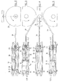
- FIG. 1 is a schematic view of a device according to the invention, while FIGS. 2 to 5 illustrate an alternative embodiment of this device.
- Figure 1 shows the engine 1 of a vehicle (not shown) comprising, conventionally, an oil pan 2 at its lower part.
- This crankcase houses an oil refill point 3 and an overflow discharge point 4 any oil.
- point 4 of evacuation is located at the barycentric point of the planes (shown in phantom) occupied by the oil surface at the oil regulation level and for different plates of the vehicle (only three plates have been shown in the figure).
- the backup point 3 is connected to the lower part of a reserve 5 of oil through a pipe 6 through a non-return valve 7 and the first pump 8 of a double pump 9.
- the discharge point 4 is connected to the upper part of the reserve 5 by a pipe 10 to the through a check valve 11 and the second pump 12 of the double pump 9.
- the two pumps 8 and 12 are mounted on a common shaft which is rotated by an electric gear motor 13. Both pumps, which therefore rotate in the same direction at an identical speed, have, by construction, different flow capacities, the flow capacity of the second pump 12 being greater than that of the first pump 8 and this regardless of the viscosity difference between the oil from the reserve 5 and the oil coming from the crankcase 2.
- the pump 12 if it is not self-priming, must be located below the point evacuation 4 so as to guarantee its priming whatever the trim of the vehicle. This condition disappears if the pump 12 is self-priming.
- the pipes 6 and 10 pass through the wall of the casing by sealed passages.
- the two non-return valves 7 and 11 can be of the ball type and spring as shown. It should be noted that the role of the valve 7 is to prevent the oil contained in reserve 5 does not flow, under the effect of gravity, into the casing 2 through the pump 8 stopped when all or part of this oil is above the maximum level of the oil contained in the housing which is usually the case when, as illustrated, the reserve 5 is located at a level higher than said level maximum oil in the crankcase. To this end the setting of the valve spring 7 must be sufficient to withstand the pressure difference caused by the maximum possible difference in oil levels in reserve 5, one part, and in the casing 2, on the other hand. For its part, the valve 11 has for function of avoiding air intake by the engine in operation under the effect reduced pressure in the housing.
- Reserve 5 can have any oil capacity sufficient to ensure topping up for a desired mileage.
- a capacity of two or three liters is usually enough for a mileage of 40,000 to 60,000 kilometers in based on an average oil consumption of 0.05 liter / 1000 kilometers.
- the reserve 5 is provided at its upper part with an air intake 15 preventing its internal volume from being depressed when oil therein is taken up by pump 8.
- the device also includes a control unit 14 of the gear motor 13, which consists of the electronic control unit of the engine usually fitted on most current vehicles after proper programming of it.
- the device of the invention is triggered when the engine, after a period of operation, has been stopped for a time t (for example from 15 to 20 minutes) sufficient to ensure the return of the oil contained in the engine at the bottom of the engine housing and provided that by elsewhere, the vehicle has traveled a certain mileage (e.g. included between 1000 and 2000 km) since it was put into service or the previous one add oil and the engine water temperature is higher than, for example, 70 ° C, to be sure that at least 95% of the oil either returned to the casing at the bottom of the engine.
- a water temperature of 70 ° C usually corresponds to an oil temperature of 40 to 80 ° C. In variant, one could, of course, substitute the oil temperature, when available, at water temperature, as a parameter of trigger.
- the unit of command 14 triggers the operation of the reduction motor 13 and, therefore, of the double pump 9, and this for a predetermined duration, by 1 minute example.
- the double pump used had the following flow rates, depending on the temperature, for a 5W30 oil: Oil temperature Booster pump flow 8 (l / min) Drain pump flow 12 (l / min) -25 ° C 0.228 1.27 0 ° C 0.244 1.37 + 20 ° C 0.228 1.27 + 40 ° C 0,204 1.15 + 50 ° C 0.156 0.88 + 80 ° C 0.044 0.25
- the flow rate of the booster pump 8 is sufficient to ensure in 1 minute, or even less, sufficient oil to compensate for normal oil consumption (0.05 liter / 1000 km) or even increased.
- FIGS 2 to 5 illustrate an alternative embodiment of the device Figure 1.
- the assembly constituted by the geared motor 13, the double pump 9 and valves 7 and 11 is replaced by a piston pump 20 and double chamber 21, 22, four ball valves 23-26 and a motor electric 27 driving a steering wheel 28 associated with a connecting rod 29 driving the rod 30 of the piston 20 of the pump in a reciprocating movement.
- FIGS 2 to 5 illustrate various phases of the operation of this variant during an oil top-up operation.
- the piston 20 is at the end of its travel, the volume of room 21 being at its minimum and room 22 being totally filled with oil previously aspirated from reserve 5 via valve 23.
- Figure 3 illustrates the retraction phase of the piston.
- the oil contained in chamber 22 is injected into the oil pan 2 of the engine, while simultaneously any overflow of incoming oil at point 4 of evacuation is sucked into the chamber 21 via the conduit 10 and the valve 25.
- Figure 4 shows the piston in the fully retracted position.
- the room 22 is reduced to its minimum volume and room 21 contains an amount of oil corresponding to the overflow reached in point 4 during the oil injection.
- FIG. 5 illustrates the advance phase of the piston. During this phase the oil contained in chamber 21 is discharged into reserve 5 via the valve 26, while the chamber 22 is filled with oil sucked from the reserve 5.
- the pump 19 has the capacity to drain from the oil pan, via point 4 and the line 10, a maximum oil flow greater than the makeup oil flow injected into the casing 2 via the conduit 6, thus avoiding any risk of overfilling.
Landscapes
- Engineering & Computer Science (AREA)
- Mechanical Engineering (AREA)
- General Engineering & Computer Science (AREA)
- Lubrication Details And Ventilation Of Internal Combustion Engines (AREA)
- Lubrication Of Internal Combustion Engines (AREA)
Abstract
Description
- la suppression du risque de sur-remplissage en huile du moteur soit par déclenchement intempestif du dispositif d'appoint à partir d'une information erronée de niveau d'huile, soit en cas de défaillance du système avec non-arrêt des moyens amenant l'huile d'appoint au moteur, risque touchant la sécurité du produit et des personnes (emballement de moteur diesel avec possibilité de perte de contrôle du véhicule),
- une implantation facilitée dans le carter d'huile du moteur : la tubulure d'évacuation du trop-plein étant moins encombrante qu'une jauge de niveau d'huile,
- une stratégie de pilotage simplifiée, ne nécessitant pas les verrous logiciels destinés à limiter les effets des défaillances de la chaíne de jaugeage de l'huile et ne nécessitant plus une validation spécifique, longue et coûteuse,
- un développement simplifié grâce à la possibilité de fonctionner uniquement avec l'unité de contrôle électronique usuelle du moteur sans besoin d'informations issues d'autres unités de commande électronique du véhicule (par exemple habitacle, tableau de bord),
- un entretien simplifié dans le réseau d'agents grâce à une moindre complexité du système.
| Température de l'huile | Débit de la pompe d'appoint 8 (l/mn) | Débit de la pompe d'évacuation 12 (l/mn) |
| -25°C | 0,228 | 1,27 |
| 0°C | 0,244 | 1,37 |
| +20°C | 0,228 | 1,27 |
| +40°C | 0,204 | 1,15 |
| +50°C | 0,156 | 0,88 |
| +80°C | 0,044 | 0,25 |
Claims (6)
- Un dispositif automatique d'appoint d'huile dans le carter d'huile (2) du moteur à explosion d'un véhicule qui comprend une réserve (5) d'huile reliée par une première tubulure (6) à un point d'ajout (3) d'huile dans ledit carter et par une deuxième tubulure (10) à un point d'évacuation (4) du trop-plein éventuel d'huile dans ledit carter, caractérisé en ce qu'il comprend, en outre :des moyens (8, 12, 14) permettant à la fois de transférer de l'huile à partir de ladite réserve vers ledit point d'ajout d'huile et, simultanément, d'évacuer tout trop-plein d'huile éventuel par ledit point d'évacuation en direction de ladite réserve, la capacité de débit d'huile évacuable par lesdits moyens étant supérieure au débit d'huile ajouté ; et des moyens de commande desdits moyens de transfert et d'évacuation assurant la mise en marche de ces derniers après une durée prédéterminée depuis l'arrêt du moteur et pourvu que (a) la température de l'huile dans le carter ou la température de l'eau de refroidissement du moteur se trouve dans une gamme de température prédéterminée et (b) un kilométrage minimum prédéterminé ait été parcouru par le véhicule depuis la mise en service du véhicule ou l'opération d'appoint d'huile précédente.
- Un dispositif selon la revendication 1, caractérisé en ce que le point d'évacuation (4) d'huile est situé approximativement au point barycentrique des positions du niveau de régulation de l'huile contenue dans le carter.
- Un dispositif selon la revendication 1, caractérisé en ce que les moyens de transfert et d'évacuation d'huile comprennent une pompe rotative double (9).
- Un dispositif selon la revendication 1, caractérisé en ce que les moyens de transfert et d'évacuation d'huile comprennent une pompe (19) à piston (20) et à double chambre (21, 22).
- Un dispositif selon la revendication 3 ou 4, caractérisé en ce que la pompe est associée à des clapets (7, 11, 23-26).
- Un dispositif selon la revendication 1, caractérisé en ce que les moyens de commande sont constitués, au moins en partie, de l'unité de contrôle électronique (14) du moteur du véhicule.
Applications Claiming Priority (2)
| Application Number | Priority Date | Filing Date | Title |
|---|---|---|---|
| FR0101502A FR2820458B1 (fr) | 2001-02-05 | 2001-02-05 | Dispositif automatique de regulation du niveau d'huile dans un moteur thermique a 4 temps |
| FR0101502 | 2001-02-05 |
Publications (2)
| Publication Number | Publication Date |
|---|---|
| EP1229218A1 true EP1229218A1 (fr) | 2002-08-07 |
| EP1229218B1 EP1229218B1 (fr) | 2009-06-17 |
Family
ID=8859604
Family Applications (1)
| Application Number | Title | Priority Date | Filing Date |
|---|---|---|---|
| EP20020290232 Expired - Lifetime EP1229218B1 (fr) | 2001-02-05 | 2002-02-01 | Dispositif automatique de régulation du niveau d' huile dans un moteur thermique à 4 temps |
Country Status (3)
| Country | Link |
|---|---|
| EP (1) | EP1229218B1 (fr) |
| DE (1) | DE60232614D1 (fr) |
| FR (1) | FR2820458B1 (fr) |
Cited By (3)
| Publication number | Priority date | Publication date | Assignee | Title |
|---|---|---|---|---|
| CN107345493A (zh) * | 2016-05-05 | 2017-11-14 | 上海汽车集团股份有限公司 | 液面调节装置及调节方法、润滑系统及润滑油更换系统 |
| CN108590805A (zh) * | 2018-03-29 | 2018-09-28 | 华为技术有限公司 | 一种发动机润滑系统及其补油、装配方法、发动机 |
| CN119957344A (zh) * | 2025-01-14 | 2025-05-09 | 比亚迪股份有限公司 | 油路系统、动力总成和车辆 |
Citations (5)
| Publication number | Priority date | Publication date | Assignee | Title |
|---|---|---|---|---|
| FR2338378A1 (fr) | 1976-01-14 | 1977-08-12 | Mtu Friedrichshafen Gmbh | Installation permettant d'alimenter un moteur a combustion interne en huile de graissage |
| EP0345041A2 (fr) * | 1988-05-31 | 1989-12-06 | Honda Giken Kogyo Kabushiki Kaisha | Structure de carter d'huile pour moteur à combustion interne |
| US5701862A (en) * | 1994-05-26 | 1997-12-30 | Nippon Oil Company Limited | Method and apparatus for replenishing the lubricating oil of an internal combustion engine |
| EP0928883A1 (fr) * | 1998-01-12 | 1999-07-14 | The Lubrizol Corporation | Dispositif pour maintenir la qualité et le niveau de lubrifiant dans un moteur a combustion |
| FR2803873A1 (fr) | 2000-01-14 | 2001-07-20 | Renault | Dispositif et procede de regulation du niveau de l'huile dans un carter de moteur thermique |
Family Cites Families (5)
| Publication number | Priority date | Publication date | Assignee | Title |
|---|---|---|---|---|
| JPS5521225A (en) | 1978-07-31 | 1980-02-15 | Matsushita Electric Works Ltd | Production of compound for phenolic resin formation material |
| JPS5826519A (ja) | 1981-08-07 | 1983-02-17 | 日本電気株式会社 | ガスダム付スタッブケ−ブルの気密保持構造 |
| JPH082934B2 (ja) | 1989-05-30 | 1996-01-17 | 三菱化学株式会社 | ゴム変性スチレン系樹脂の製造方法及び樹脂組成物 |
| FR2729714B1 (fr) | 1995-01-20 | 1997-04-25 | Caquot Jean Pierre | Dispositif de controle, de mise a niveau et de vidange de la reserve d'huile du moteur d'un vehicule |
| FR2735814B1 (fr) | 1995-06-22 | 1997-10-17 | Faugere Andre | Dispositif de retablissement du niveau d'huile dans un carter de vehicule automobile |
-
2001
- 2001-02-05 FR FR0101502A patent/FR2820458B1/fr not_active Expired - Fee Related
-
2002
- 2002-02-01 DE DE60232614T patent/DE60232614D1/de not_active Expired - Lifetime
- 2002-02-01 EP EP20020290232 patent/EP1229218B1/fr not_active Expired - Lifetime
Patent Citations (5)
| Publication number | Priority date | Publication date | Assignee | Title |
|---|---|---|---|---|
| FR2338378A1 (fr) | 1976-01-14 | 1977-08-12 | Mtu Friedrichshafen Gmbh | Installation permettant d'alimenter un moteur a combustion interne en huile de graissage |
| EP0345041A2 (fr) * | 1988-05-31 | 1989-12-06 | Honda Giken Kogyo Kabushiki Kaisha | Structure de carter d'huile pour moteur à combustion interne |
| US5701862A (en) * | 1994-05-26 | 1997-12-30 | Nippon Oil Company Limited | Method and apparatus for replenishing the lubricating oil of an internal combustion engine |
| EP0928883A1 (fr) * | 1998-01-12 | 1999-07-14 | The Lubrizol Corporation | Dispositif pour maintenir la qualité et le niveau de lubrifiant dans un moteur a combustion |
| FR2803873A1 (fr) | 2000-01-14 | 2001-07-20 | Renault | Dispositif et procede de regulation du niveau de l'huile dans un carter de moteur thermique |
Cited By (4)
| Publication number | Priority date | Publication date | Assignee | Title |
|---|---|---|---|---|
| CN107345493A (zh) * | 2016-05-05 | 2017-11-14 | 上海汽车集团股份有限公司 | 液面调节装置及调节方法、润滑系统及润滑油更换系统 |
| CN107345493B (zh) * | 2016-05-05 | 2020-07-28 | 上海汽车集团股份有限公司 | 一种发动机润滑系统的调节润滑油液面的方法 |
| CN108590805A (zh) * | 2018-03-29 | 2018-09-28 | 华为技术有限公司 | 一种发动机润滑系统及其补油、装配方法、发动机 |
| CN119957344A (zh) * | 2025-01-14 | 2025-05-09 | 比亚迪股份有限公司 | 油路系统、动力总成和车辆 |
Also Published As
| Publication number | Publication date |
|---|---|
| FR2820458B1 (fr) | 2003-06-20 |
| EP1229218B1 (fr) | 2009-06-17 |
| FR2820458A1 (fr) | 2002-08-09 |
| DE60232614D1 (de) | 2009-07-30 |
Similar Documents
| Publication | Publication Date | Title |
|---|---|---|
| EP0614002B1 (fr) | Procédé et dispositif d'injection automatique d'un additif dans le réservoir de carburant d'un véhicule automobile | |
| EP0058619B1 (fr) | Moteur thermique à quatre temps susceptible de surpuissance temporaire | |
| FR2723985A1 (fr) | Systeme de pompe a huile | |
| EP0943476A1 (fr) | Circuit de mise à l'air pour réservoir à liquide | |
| WO2019243710A1 (fr) | Ensemble pour turbomachine d'aeronef comportant un systeme ameliore de lubrification d'un reducteur d'entrainement de soufflante en cas d'autorotation de la soufflante | |
| EP1643139B1 (fr) | Dispositif de valve d'échange | |
| FR3017652A1 (fr) | Procede de controle de la viscosite de l'huile de lubrification d'un moteur thermique | |
| EP1229218B1 (fr) | Dispositif automatique de régulation du niveau d' huile dans un moteur thermique à 4 temps | |
| FR2836709A1 (fr) | Mecanisme a engrenages a dispositif de controle pour la creation d'une atmosphere rarefiee | |
| FR2551139A1 (fr) | Demarreur a commande par air comprime, notamment pour moteurs a combustion interne | |
| FR2666390A1 (fr) | Embrayage hydraulique. | |
| FR2581700A1 (fr) | Dispositif d'accroissement de la quantite d'huile circulant dans un moteur a combustion interne | |
| FR2491128A1 (fr) | Procede et dispositif pour le recyclage thermiquement optimal dans des appareils d'echappement a postcombustion de moteurs thermiques | |
| FR2667583A1 (fr) | Dispositif de puisage de liquide dans un reservoir a plusieurs compartiments et reservoir equipe d'un tel dispositif. | |
| EP1040258B1 (fr) | Systemes de prelubrification et procede correspondant | |
| FR2816354A1 (fr) | Dispositif de lubrification pour moteur a combustion interne | |
| WO2002057602A9 (fr) | Appareil regulateur de niveau de fluide lubrifiant | |
| FR2646225A1 (fr) | Dispositif de lubrification des paliers d'un turbo-compresseur | |
| EP0048070A1 (fr) | Procédé et dispositif pour la récolte d'huile de lubrification usée en vue de son recyclage | |
| EP1598532B1 (fr) | Dispositif de lubrification d'un moteur à combustion interne | |
| WO2021198602A1 (fr) | Ensemble pour turbomachine d'aeronef comportant un systeme ameliore de lubrification d'un reducteur d'entrainement de soufflante | |
| EP0091348B1 (fr) | Valve de régulation pour alimentation simultanée de systèmes hydrauliques à centre fermé et à centre ouvert | |
| FR2588609A1 (fr) | Regulateur de niveau, notamment pour carter d'huile de moteur a combustion interne. | |
| EP0428418B1 (fr) | Système de recyclage d'huile pour moteurs à deux temps à lubrification separée | |
| FR2936842A1 (fr) | Systeme d'injection a reservoir de moteur a combustion interne |
Legal Events
| Date | Code | Title | Description |
|---|---|---|---|
| PUAI | Public reference made under article 153(3) epc to a published international application that has entered the european phase |
Free format text: ORIGINAL CODE: 0009012 |
|
| AK | Designated contracting states |
Kind code of ref document: A1 Designated state(s): AT BE CH CY DE DK ES FI FR GB GR IE IT LI LU MC NL PT SE TR |
|
| AX | Request for extension of the european patent |
Free format text: AL;LT;LV;MK;RO;SI |
|
| RAP1 | Party data changed (applicant data changed or rights of an application transferred) |
Owner name: RENAULT S.A.S. |
|
| 17P | Request for examination filed |
Effective date: 20030131 |
|
| AKX | Designation fees paid |
Designated state(s): BE DE ES GB |
|
| 17Q | First examination report despatched |
Effective date: 20080923 |
|
| GRAP | Despatch of communication of intention to grant a patent |
Free format text: ORIGINAL CODE: EPIDOSNIGR1 |
|
| GRAS | Grant fee paid |
Free format text: ORIGINAL CODE: EPIDOSNIGR3 |
|
| GRAA | (expected) grant |
Free format text: ORIGINAL CODE: 0009210 |
|
| AK | Designated contracting states |
Kind code of ref document: B1 Designated state(s): BE DE ES GB |
|
| REG | Reference to a national code |
Ref country code: GB Ref legal event code: FG4D Free format text: NOT ENGLISH |
|
| REF | Corresponds to: |
Ref document number: 60232614 Country of ref document: DE Date of ref document: 20090730 Kind code of ref document: P |
|
| PG25 | Lapsed in a contracting state [announced via postgrant information from national office to epo] |
Ref country code: ES Free format text: LAPSE BECAUSE OF FAILURE TO SUBMIT A TRANSLATION OF THE DESCRIPTION OR TO PAY THE FEE WITHIN THE PRESCRIBED TIME-LIMIT Effective date: 20090928 |
|
| PLBE | No opposition filed within time limit |
Free format text: ORIGINAL CODE: 0009261 |
|
| STAA | Information on the status of an ep patent application or granted ep patent |
Free format text: STATUS: NO OPPOSITION FILED WITHIN TIME LIMIT |
|
| 26N | No opposition filed |
Effective date: 20100318 |
|
| BERE | Be: lapsed |
Owner name: RENAULT S.A.S. Effective date: 20100228 |
|
| PG25 | Lapsed in a contracting state [announced via postgrant information from national office to epo] |
Ref country code: BE Free format text: LAPSE BECAUSE OF NON-PAYMENT OF DUE FEES Effective date: 20100228 |
|
| PGFP | Annual fee paid to national office [announced via postgrant information from national office to epo] |
Ref country code: DE Payment date: 20170217 Year of fee payment: 16 |
|
| PGFP | Annual fee paid to national office [announced via postgrant information from national office to epo] |
Ref country code: GB Payment date: 20170216 Year of fee payment: 16 |
|
| REG | Reference to a national code |
Ref country code: DE Ref legal event code: R119 Ref document number: 60232614 Country of ref document: DE |
|
| GBPC | Gb: european patent ceased through non-payment of renewal fee |
Effective date: 20180201 |
|
| PG25 | Lapsed in a contracting state [announced via postgrant information from national office to epo] |
Ref country code: DE Free format text: LAPSE BECAUSE OF NON-PAYMENT OF DUE FEES Effective date: 20180901 |
|
| PG25 | Lapsed in a contracting state [announced via postgrant information from national office to epo] |
Ref country code: GB Free format text: LAPSE BECAUSE OF NON-PAYMENT OF DUE FEES Effective date: 20180201 |