EP1229068A1 - Méthode et dispositif pour modifier la surface intérieure de récipients en plastique - Google Patents
Méthode et dispositif pour modifier la surface intérieure de récipients en plastique Download PDFInfo
- Publication number
- EP1229068A1 EP1229068A1 EP02002554A EP02002554A EP1229068A1 EP 1229068 A1 EP1229068 A1 EP 1229068A1 EP 02002554 A EP02002554 A EP 02002554A EP 02002554 A EP02002554 A EP 02002554A EP 1229068 A1 EP1229068 A1 EP 1229068A1
- Authority
- EP
- European Patent Office
- Prior art keywords
- reception chamber
- container
- modifying
- container made
- polymeric compound
- Prior art date
- Legal status (The legal status is an assumption and is not a legal conclusion. Google has not performed a legal analysis and makes no representation as to the accuracy of the status listed.)
- Granted
Links
- 229920000642 polymer Polymers 0.000 title claims description 23
- 238000000034 method Methods 0.000 title claims description 19
- 150000002500 ions Chemical class 0.000 claims abstract description 17
- OKTJSMMVPCPJKN-UHFFFAOYSA-N Carbon Chemical compound [C] OKTJSMMVPCPJKN-UHFFFAOYSA-N 0.000 claims abstract description 8
- 229910052799 carbon Inorganic materials 0.000 claims abstract description 8
- 229920000139 polyethylene terephthalate Polymers 0.000 claims description 92
- 239000005020 polyethylene terephthalate Substances 0.000 claims description 92
- 239000007789 gas Substances 0.000 claims description 44
- CURLTUGMZLYLDI-UHFFFAOYSA-N Carbon dioxide Chemical compound O=C=O CURLTUGMZLYLDI-UHFFFAOYSA-N 0.000 claims description 36
- QVGXLLKOCUKJST-UHFFFAOYSA-N atomic oxygen Chemical compound [O] QVGXLLKOCUKJST-UHFFFAOYSA-N 0.000 claims description 18
- 229910002092 carbon dioxide Inorganic materials 0.000 claims description 18
- 239000001569 carbon dioxide Substances 0.000 claims description 18
- 239000001301 oxygen Substances 0.000 claims description 18
- 229910052760 oxygen Inorganic materials 0.000 claims description 18
- 239000000463 material Substances 0.000 claims description 16
- 239000002344 surface layer Substances 0.000 claims description 9
- -1 polyethylene terephthalate Polymers 0.000 claims description 3
- 229920003002 synthetic resin Polymers 0.000 claims 2
- 239000000057 synthetic resin Substances 0.000 claims 2
- 239000007943 implant Substances 0.000 claims 1
- XKRFYHLGVUSROY-UHFFFAOYSA-N Argon Chemical compound [Ar] XKRFYHLGVUSROY-UHFFFAOYSA-N 0.000 description 36
- 230000007246 mechanism Effects 0.000 description 31
- 230000003028 elevating effect Effects 0.000 description 24
- 229910052786 argon Inorganic materials 0.000 description 18
- 238000011022 operating instruction Methods 0.000 description 15
- 235000013361 beverage Nutrition 0.000 description 10
- 230000000630 rising effect Effects 0.000 description 8
- 229910021385 hard carbon Inorganic materials 0.000 description 7
- 230000000694 effects Effects 0.000 description 6
- 239000010410 layer Substances 0.000 description 6
- 230000000717 retained effect Effects 0.000 description 6
- 239000004020 conductor Substances 0.000 description 4
- 230000007547 defect Effects 0.000 description 4
- 238000005468 ion implantation Methods 0.000 description 4
- 230000008569 process Effects 0.000 description 4
- 239000010453 quartz Substances 0.000 description 4
- VYPSYNLAJGMNEJ-UHFFFAOYSA-N silicon dioxide Inorganic materials O=[Si]=O VYPSYNLAJGMNEJ-UHFFFAOYSA-N 0.000 description 4
- 235000013405 beer Nutrition 0.000 description 3
- 235000014171 carbonated beverage Nutrition 0.000 description 3
- 239000007788 liquid Substances 0.000 description 3
- 239000011248 coating agent Substances 0.000 description 2
- 238000000576 coating method Methods 0.000 description 2
- 239000011810 insulating material Substances 0.000 description 2
- 239000011295 pitch Substances 0.000 description 2
- IJGRMHOSHXDMSA-UHFFFAOYSA-N Atomic nitrogen Chemical compound N#N IJGRMHOSHXDMSA-UHFFFAOYSA-N 0.000 description 1
- 239000004215 Carbon black (E152) Substances 0.000 description 1
- 238000010420 art technique Methods 0.000 description 1
- 238000010276 construction Methods 0.000 description 1
- 229910001873 dinitrogen Inorganic materials 0.000 description 1
- 229930195733 hydrocarbon Natural products 0.000 description 1
- 150000002430 hydrocarbons Chemical class 0.000 description 1
- 229910052500 inorganic mineral Inorganic materials 0.000 description 1
- 239000012212 insulator Substances 0.000 description 1
- 239000011707 mineral Substances 0.000 description 1
- 230000035699 permeability Effects 0.000 description 1
- 239000002994 raw material Substances 0.000 description 1
- 230000002787 reinforcement Effects 0.000 description 1
- XLYOFNOQVPJJNP-UHFFFAOYSA-N water Substances O XLYOFNOQVPJJNP-UHFFFAOYSA-N 0.000 description 1
Images

Classifications
-
- C—CHEMISTRY; METALLURGY
- C08—ORGANIC MACROMOLECULAR COMPOUNDS; THEIR PREPARATION OR CHEMICAL WORKING-UP; COMPOSITIONS BASED THEREON
- C08J—WORKING-UP; GENERAL PROCESSES OF COMPOUNDING; AFTER-TREATMENT NOT COVERED BY SUBCLASSES C08B, C08C, C08F, C08G or C08H
- C08J7/00—Chemical treatment or coating of shaped articles made of macromolecular substances
- C08J7/12—Chemical modification
- C08J7/123—Treatment by wave energy or particle radiation
-
- C—CHEMISTRY; METALLURGY
- C23—COATING METALLIC MATERIAL; COATING MATERIAL WITH METALLIC MATERIAL; CHEMICAL SURFACE TREATMENT; DIFFUSION TREATMENT OF METALLIC MATERIAL; COATING BY VACUUM EVAPORATION, BY SPUTTERING, BY ION IMPLANTATION OR BY CHEMICAL VAPOUR DEPOSITION, IN GENERAL; INHIBITING CORROSION OF METALLIC MATERIAL OR INCRUSTATION IN GENERAL
- C23C—COATING METALLIC MATERIAL; COATING MATERIAL WITH METALLIC MATERIAL; SURFACE TREATMENT OF METALLIC MATERIAL BY DIFFUSION INTO THE SURFACE, BY CHEMICAL CONVERSION OR SUBSTITUTION; COATING BY VACUUM EVAPORATION, BY SPUTTERING, BY ION IMPLANTATION OR BY CHEMICAL VAPOUR DEPOSITION, IN GENERAL
- C23C14/00—Coating by vacuum evaporation, by sputtering or by ion implantation of the coating forming material
- C23C14/04—Coating on selected surface areas, e.g. using masks
- C23C14/046—Coating cavities or hollow spaces, e.g. interior of tubes; Infiltration of porous substrates
-
- C—CHEMISTRY; METALLURGY
- C23—COATING METALLIC MATERIAL; COATING MATERIAL WITH METALLIC MATERIAL; CHEMICAL SURFACE TREATMENT; DIFFUSION TREATMENT OF METALLIC MATERIAL; COATING BY VACUUM EVAPORATION, BY SPUTTERING, BY ION IMPLANTATION OR BY CHEMICAL VAPOUR DEPOSITION, IN GENERAL; INHIBITING CORROSION OF METALLIC MATERIAL OR INCRUSTATION IN GENERAL
- C23C—COATING METALLIC MATERIAL; COATING MATERIAL WITH METALLIC MATERIAL; SURFACE TREATMENT OF METALLIC MATERIAL BY DIFFUSION INTO THE SURFACE, BY CHEMICAL CONVERSION OR SUBSTITUTION; COATING BY VACUUM EVAPORATION, BY SPUTTERING, BY ION IMPLANTATION OR BY CHEMICAL VAPOUR DEPOSITION, IN GENERAL
- C23C14/00—Coating by vacuum evaporation, by sputtering or by ion implantation of the coating forming material
- C23C14/22—Coating by vacuum evaporation, by sputtering or by ion implantation of the coating forming material characterised by the process of coating
- C23C14/48—Ion implantation
-
- H—ELECTRICITY
- H01—ELECTRIC ELEMENTS
- H01J—ELECTRIC DISCHARGE TUBES OR DISCHARGE LAMPS
- H01J37/00—Discharge tubes with provision for introducing objects or material to be exposed to the discharge, e.g. for the purpose of examination or processing thereof
- H01J37/32—Gas-filled discharge tubes
- H01J37/32009—Arrangements for generation of plasma specially adapted for examination or treatment of objects, e.g. plasma sources
- H01J37/32412—Plasma immersion ion implantation
Definitions
- the present invention relates to a method and apparatus for modifying the surface of a container made of a polymeric compound, and more particularly relates to a method and apparatus for modifying the interior side surface of, for example, a PET (polyethylene terephthalate) container into a material having low permeability to gases, such as DLC (diamond-like carbon) .
- a PET polyethylene terephthalate
- DLC diamond-like carbon
- PET containers are often used as containers for beverages because of their light weight, impact-resistance and resealability.
- the PET containers had a defect that they were permeated by oxygen and carbon dioxide. Accordingly, the PET containers were inadequate for use as containers filled with beer or carbonated beverages. Thus, the PET containers had a defect that they could not be used as containers for such beverages.
- only the inner surface of a PET container can be coated with a hard carbon film so that permeation of oxygen or carbon dioxide can be blocked by the hard carbon film.
- a method for modifying a surface of a container made of a polymeric compound containing carbon including the step of: implanting ions into the container so as to modify a surface layer of the container into a material that is not permeable by carbon dioxide gas and oxygen or a material that is hard to be permeated by carbon dioxide gas and oxygen.
- apparatus for modifying a surface of a container made of a polymeric compound including: a reception chamber which can receive the container while keeping airtightness; a vacuum pump for evacuating the reception chamber; a plasma generating unit for generating plasma in the reception chamber; an electrode inserted into the container received in the reception chamber; and a high voltage power source for applying high voltage pulses to the electrode; wherein an interior side surface layer of the container received in the reception chamber is modified into a material that is not permeable by carbon dioxide gas and oxygen or a material that is hard to be permeated by carbon dioxide gas and oxygen.
- the surface layer of the container made of a polymeric compound can be modified into a material that is not permeable by carbon dioxide gas and oxygen or a material that is hard to be permeated by carbon dioxide gas and oxygen.
- a polymeric compound container which is not permeated or is hard to be permeated by carbon dioxide gas or oxygen.
- the surface layer of the container itself is modified, there is no fear that the modified surface layer peels off.
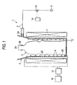
- a modifying apparatus 1 modifies the interior side surface of a PET container 2.
- This modifying apparatus 1 has a cup-like reception chamber 3 which can receive the PET container 2, a cover 4 for closing a top opening of the reception chamber 3, a tube-like electrode 5 provided in the cover 4, a coil 6 disposed in an inner circumferential portion of the reception chamber 3, and a solenoid coil 7 disposed to surround the reception chamber 3 and the coil 6.
- the PET container 2 having a surface which will be modified by the modifying apparatus 1 has an opening portion 2A at its top, and a threaded portion 2B in the outer circumferential portion of the top. A not-shown cap is screwed to the threaded portion 2B.
- the PET container 2 is transparent and colorless, and a plurality of annular projections 2C are formed at required places of its body for the purpose of reinforcement. That is, the PET container 2 having a surface which will be modified by the modifying apparatus 1 is a general PET container known in the related art, and is designed so that liquid such as beverage is filled into the inside of the PET container 2 through the opening portion 2A.
- the PET container 2 configured thus is supplied into the reception chamber 3 so that the opening portion 2A faces upward.
- the reception chamber 3 is made of a conductive material and formed into a cup-like shape with a wide mouth in the top portion.
- a suction port 3A is formed in a position close to the top portion.
- a normally closed electromagnetic on-off valve 13 is provided in the middle of the conduit 8. The operation of the electromagnetic on-off valve 13 is controlled by a control unit 14.
- the reception chamber 3 When the electromagnetic on-off valve 13 is opened by the control unit 14, the reception chamber 3 is evacuated through the conduit 8 and the suction port 3A.
- the reception chamber 3 made of a conductive material is electrically connected to a constant voltage body such as the ground.
- the cover 4 is made of a conductive material formed into a disc-like shape.
- the cover 4 can be moved up and down above the reception chamber 3 by a not-shown elevating mechanism.
- a through hole 4A is formed at a center portion of the cover 4.
- a support portion 5A of the electrode 5 penetrates the through hole 4A slidably while keeping airtightness.
- the support portion 5A is formed out of a cylindrical insulating material, and fitted in a predetermined position of the electrode 5.
- an annular seal member 29 is planted in the outer circumferential portion of the lower surface of the cover 4.
- the electrode 5 is made of a conductive pipe, and electrically connected to a DC high voltage power source 15.
- the upper end portion of the electrode 5 is made to project over the upper surface of the cover 4.
- One end of a conduit 16 is connected to the upper end portion of the electrode 5.
- the other end of the conduit 16 is connected to a gas supply source 12.
- argon gas is reserved in the gas supply source 12.
- Anormally closed electromagnetic on-off valve 21 is provided in the middle of the conduit 16. The operation of the electromagnetic on-off valve 21 is also controlled by the control unit 14. When the electromagnetic on-off valve 21 is opened by the control unit 14, argon gas is supplied into the reception chamber 3 from the supply source 12 through the conduit 16. In such a manner, the electrode 5 also serves as a gas introduction tube in this embodiment.
- the PET container 2 is received in the reception chamber 3 by a not-shown conveying mechanism in the state where the cover 4 is located in its rising limit position apart from the top of the reception chamber 3 by the elevating mechanism. After that, the cover 4 is moved down to its falling limit position by the elevating mechanism so that the electrode 5 is inserted into the container 2 in the reception chamber 3. After that, the cover 4 is mounted on the top portion of the reception chamber 3 so as to close the top opening portion of the reception chamber 3. In this airtight state, the reception chamber 3 is evacuated through the conduit 8, and argon gas is then supplied to the whole area of the internal space of the reception chamber 3 including the internal space of the PET container 2 through the conduit 16 and the electrode 5.
- the support portion 5A of the electrode 5 is located on the interior side of the top opening portion 2A and the threaded portion 2B of the PET container 2.
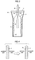
- the electrode 5 itself can be further lifted up by a predetermined distance relatively to the cover 4 by the elevating mechanism (Fig. 3).
- the support portion 5A made of an insulating material is located above the top opening portion 2A of the PET container 2.
- the operation of the DC high voltage power source 15 connected to the electrode 5 is controlled by the control unit 14.
- the high voltage power source 15 is designed to apply positive high voltage pulses to the electrode 5 when an operating instruction is transmitted from the control unit 14 to the high voltage power source 15.
- the coil 6 provided in the inner circumferential portion of the reception chamber 3 is electrically insulated from the reception chamber 3.
- the coil 6 is connected to a high frequency power source 18 ranging from several of MHz to several hundreds of MHz through a matching circuit 17 disposed outside the reception chamber 3.
- the operation of the high frequency power source 18 is also controlled by the control unit 14.
- the high frequency power source 18 is designed to apply a high frequency current ranging from several of MHz to several hundreds of MHz to the coil 6 when an operating instruction is transmitted from the control unit 14 to the high frequency power source 18.
- the solenoid coil 7 disposed to surround the reception chamber 3 is connected to a not-shown power source.
- the solenoid coil 7 is excited to generate a DC magnetic field.
- a plasma generating unit for generating plasma is constituted by the coil 6, the matching circuit 17 and the high frequency power source 18.
- the interior side surface of the PET container 2 is modified through the following process by the modifying apparatus 1.
- the cover 4 is retained in its rising limit position apart from and above the top portion of the reception chamber 3 by a not-shown elevating mechanism. In this state, the PET container 2 is conveyed to a position above the reception chamber 3 by a not-shown conveying mechanism and then received in the reception chamber 3 (Fig. 1).
- the cover 4 is moved down to its falling limit position by the elevating mechanism.
- the electrode 5 is inserted into the PET container 2 through the opening portion 2A while the top opening portion of the reception chamber 3 is made airtight by the cover 4 (Fig. 2).
- control unit 14 switches the power source for the solenoid coil 7 so as to make a current flow into the solenoid coil 7 and thereby excite the solenoid coil 7.
- a magnetic field is generated all over the internal space of the reception chamber 3 receiving the PET container 2.
- control unit 14 opens the electromagnetic on-off valve 13 for a predetermined period of time.
- the reception chamber 3 is evacuated through the conduit 8 so that the pressure in the internal space of the reception chamber 3 becomes lower than the atmospheric pressure.
- the control unit 14 opens the electromagnetic on-off valve 21 provided in the conduit 16 for a predetermined period of time.
- argon gas is introduced into the internal space of the PET container 2 through the conduit 16. That is, the argon gas intervenes between the spaces inside and outside the PET container 2 in the reception chamber 3.
- control unit 14 transmits an operating instruction to the high frequency power source 18 so that a high frequency current ranging from several of MHz to several hundreds of MHz is applied from the high frequency power source to the coil 6.
- a high frequency current ranging from several of MHz to several hundreds of MHz is applied from the high frequency power source to the coil 6.
- plasma is generated in the reception chamber 3.
- control unit 14 transmits an operating instruction to the high voltage power source 15 so that a series of positive high voltage pulses are applied from the high voltage power source 15 to the electrode 5.
- ions of the plasma interior the PET container 2 are implanted into its interior side surface.
- the PET container 2 is an insulator
- the surface potential increases due to the ion charge-up during ion implantation.
- the surface is exposed to the plasma during the pause of the pulse.
- the surface is neutralized to recover its original potential. Then, ion implantation is carried out again until the next pulse.
- the electrode 5 is moved up by a predetermined height relatively to the cover 4 by the elevating mechanism (Fig. 3). Then, high voltage pulses are applied to carry out ion implantation again. Accordingly, the support portion 5A of the electrode 5 is supported above the top portion of the PET container 2. Thus, ions are also implanted surely into the interior side surface of the threaded portion 2B where the support portion 5A had been located.
- ions are implanted thus into the whole area of the interior side surface of the PET container 2. Accordingly, the material itself of the interior side surface of the PET container 2 originally containing carbon are modified into DLC (diamond-like carbon) throughout (see Fig. 4). That is, in this embodiment, the original surface of the PET container 2 is not coated with DLC but the material itself of the surface of the PET container 2 is modified into DLC so that a DLC layer 22 is formed all over the interior side surface as shown on the right of Fig. 4.
- DLC diamond-like carbon
- the electrode 5 does not always have to be moved up to the position in Fig. 3 from the position in Fig. 2 after ion implantation.
- the cover 4 is moved up to its rising limit position by the elevating mechanism so as to open the reception chamber 3 and extract the electrode 5 from the PET container 2.
- the cover 4 is not moved up directly in the state where the reception chamber 3 is closed, but moved up by the elevating mechanism after the reception chamber 3 is once made open to the atmosphere through the conduit 8.
- the PET container 2 subjected to the treatment is extracted by a not-shown extracting mechanism, while a new PET container 2 is received in the reception chamber 3. Then, the interior side surface of the new PET container 2 is modified into a DLC layer 22 in the process described above.
- the whole area of the interior side surface of the PET container 2 is modified into the DLC layer 22. Accordingly, it is possible to provide the PET container 2 which is transparent and colorless or slightly colored and which can prevent the permeation of carbon dioxide gas and oxygen or is hard to be permeated by carbon dioxide gas and oxygen. It is therefore possible to provide the PET container 2 which is suitable not only as a container for general beverages such as mineral water but also a container for carbonated beverages such as beer.
- the material itself of the interior side surface of the PET container 2 is modified into DLC.
- the DLC layer 22 peels off. Accordingly, after liquid such as a beverage is filled up into the PET container 2, there is no fear that pieces of peeled DLC are mixed into the liquid. It is possible to provide a safe container for beverage use.
- the period of time required for forming the DLC layer 22 in the interior side surface of the PET container 2 in this embodiment is one over several parts in the related-art technique in which the surface is coated with a DLC film. It is therefore possible to provide the modifying apparatus 1 and the modifying method fast in treatment speed.
- the PET container 2 having an interior side surface which has been modified according to this embodiment can be recycled throughout.
- argon gas reserved in the gas supply source 12 is supplied into the reception chamber 3
- hydrocarbon gas or nitrogen gas may be used in place of the argon gas.
- the following configuration may be adopted as a second embodiment of the modifying apparatus 1. That is, the gas supply source 12, the conduit 16 and the electromagnetic on-off valve 21 in the first embodiment shown in Figs. 1 to 3 may be omitted in the second embodiment, while the others are arranged similarly to those in the first embodiment.
- the second embodiment not a pipe-like one but a rod-like one is used as the electrode 5 .
- a plasma generating unit for generating plasma is constituted by the coil 6, the matching circuit 17 and the high frequency power source 18.
- treatment is carried out in the following process.
- the PET container 2 is conveyed to a position above the reception chamber 3 by a not-shown conveying mechanism, and then received in the reception chamber 3.
- the cover 4 is moved down to its falling limit position by the elevating mechanism.
- the electrode 5 is inserted into the PET container 2 while the top opening portion of the reception chamber 3 is closed by the cover 4.
- control unit 14 switches the power source for the solenoid coil 7 so as to make a current flow into the solenoid coil 7 to thereby excite the solenoid coil 7.
- a magnetic field is generated in the reception chamber 3.
- control unit 14 opens the electromagnetic on-off valve 13 for a predetermined period of time.
- the reception chamber 3 is evacuated.
- control unit 14 transmits an operating instruction to the high frequency power source 18 so that a high frequency current ranging from several of MHz to several hundreds of MHz is applied from the high frequency power source to the coil 6.
- a high frequency current ranging from several of MHz to several hundreds of MHz is applied from the high frequency power source to the coil 6.
- plasma is generated in the reception chamber 3.
- control unit 14 transmits an operating instruction to the high voltage power source 15 so that positive high voltage pulses are applied from the high voltage power source 15 to the electrode 5.
- ions of the plasma inside the PET container 2 are implanted into the PET container 2 from its interior side surface.
- the whole area of the interior side surface of the PET container 2 is modified into a DCL layer 22.
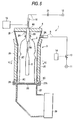
- Figs. 5 and 6 show a third embodiment of the invention.
- a plurality of permanent magnets 25 are used in place of the solenoid coil 7 in the first embodiment, and a magnetron 26 is used in place of the coil 6, the matching circuit 17 and the high frequency power source 18 likewise.
- a flange portion 3C is formed in a bottom outer circumferential portion of a cylindrical body portion.
- a quartz sheet is superposed on the lower surface of the flange portion 3C.
- a bottom surface 3B of the reception chamber 3 is constituted by the quartz sheet.
- a flange-like connection portion 27A formed on the side of a waveguide 27 is fitted to the outer circumferential portions of the quartz sheet (bottom surface 3B) and the flange portion 3C.
- an annular seal member 28 is provided between the flange portion 3C and the quartz sheet as the bottom surface 3B so as to keep airtightness between these two members.
- the magnetron 26 is connected to the other end of the waveguide 27 while keeping airtightness.
- the operation of the magnetron 26 is also controlled by the control unit 14.
- a microwave of 2.45 GHz is supplied into the reception chamber 3.
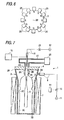
- the rod-like permanent magnets 25 are disposed at even pitches in the circumferential direction.
- the permanent magnets 25 adjacent to each other are disposed so that magnetic poles in contact with the outer circumferential surface of the reception chamber 3 are different from each other.
- a magnetic field is always formed near the inner circumferential portion of the reception chamber 3 close to these permanent magnets 25 by the permanent magnets 25.
- an annular seal member 29 is attached to the outer circumferential portion of the lower surface of the cover 4.
- a plasma generating unit for generating plasma is constituted by the waveguide 27 and the magnetron 26.
- the other configuration is the same as that in the first embodiment, and detailed description thereof will be therefore omitted.
- the surface of the PET container 2 is modified in the following manner by the modifying apparatus 1 configured thus according to the third embodiment.
- the PET container 2 conveyed by a not-shown conveying mechanism is received in the reception chamber 3.
- the cover 4 is moved down to its falling limit position by the elevating mechanism.
- the electrode 5 is inserted into the PET container 2 through the opening portion 2A while the top opening portion of the reception chamber 3 is made airtight by the cover 4 (Fig. 5).
- control unit 14 opens the electromagnetic on-off valve 13 for a predetermined period of time.
- the reception chamber 3 is evacuated through the conduit 8 so that the pressure in the internal space of the reception chamber 3 becomes lower than the atmospheric pressure.
- the control unit 14 opens the electromagnetic on-off valve 21 provided in the conduit 16 for a predetermined period of time.
- argon gas is introduced into the internal space of the PET container 2 through the conduit 16. That is, the argon gas intervenes between the spaces inside and outside the PET container 2 in the reception chamber 3.
- the pressure in the reception chamber 3 at this time is not higher than the atmospheric pressure.
- control unit 14 operates the magnetron 26 so that a microwave of 2.45 GHz is supplied from the magnetron 26 toward the bottom surface 3B of the reception chamber 3.
- the microwave is supplied into the reception chamber 3 so that plasma is generated in the argon gas in the reception chamber 3.
- control unit 14 transmits an operating instruction to the DC high voltage power source 15 so that positive high voltage pulses are applied from the high voltage power source 15 to the electrode 5.
- ions of the plasma inside the PET container 2 are implanted into its interior side surface.
- an operating instruction may be transmitted again to the high voltage power source 15.
- ions are implanted into the interior side surface of the PET container 2 again.
- Fig. 7 shows a fourth embodiment of the invention.
- a waveguide 27 and a magnetron 26 are used in place of the coil 6, the matching circuit 17 and the high frequency power source 18 in the first embodiment.
- one end of the waveguide 27 is connected to the upper surface center portion of the cover 4 made of a conductive material.
- the top portion of the electrode 5 is designed to penetrate the waveguide 27 while keeping airtightness, so as to project upward.
- An end portion of the conduit 16 is connected to the top portion of the electrode 5.
- the magnetron 26 similar to that in the third embodiment is connected to the other end of the waveguide 27 while keeping airtightness.
- the operation of the magnetron 26 is also controlled by the control unit 14. When the magnetron 26 is operated by the control unit 14, a microwave is supplied toward the bottom surface 3B of the reception chamber 3.
- the end portion of the waveguide 27 is connected to the cover 4. Therefore, a not-shown elevating mechanismmoves up the cover 4, the electrode 5 and the waveguide 27.
- an annular seal member 29 is attached to the outer circumferential portion of the lower surface of the cover 4.
- a plasma generating unit for generating plasma is constituted by the waveguide 27 and the magnetron 26.
- the other configuration is the same as that in the first embodiment, and detailed description thereof will be therefore omitted.
- the surface of the PET container 2 is modified in the following manner by the modifying apparatus 1 configured thus according to the fourth embodiment.
- the PET container 2 conveyed by a not-shown conveying mechanism is received in the reception chamber 3.
- the cover 4 and so on are moved down to their falling limit positions by the elevating mechanism.
- the electrode 5 is inserted into the PET container 2 through the opening portion 2A while the top opening portion of the reception chamber 3 is made airtight by the cover 4 (Fig. 7).
- control unit 14 switches the power source for the solenoid coil 7 so as to make a current flow into the solenoid coil 7 to thereby excite the solenoid coil 7.
- a magnetic field is formed in the reception chamber 3.
- control unit 14 opens the electromagnetic on-off valve 13 for a predetermined period of time.
- the reception chamber 3 is evacuated through the conduit 8 so that the pressure in the internal space of the reception chamber 3 becomes lower than the atmospheric pressure.
- the control unit 14 opens the electromagnetic on-off valve 21 provided in the conduit 16 for a predetermined period of time.
- argon gas is introduced into the internal space of the PET container 2 through the conduit 16. That is, the argon gas intervenes between the spaces inside and outside the PET container 2 in the reception chamber 3.
- the pressure in the reception chamber 3 at this time is not higher than the atmospheric pressure.
- control unit 14 operates the magnetron 26 so that a microwave is supplied from the magnetron 26 toward the cover 4.
- plasma is generated in the argon gas in the reception chamber 3.
- control unit 14 transmits an operating instruction to the DC high voltage power source 15 so that positive high voltage pulses are applied from the high voltage power source 15 to the electrode 5.
- ions in the plasma on the interior side of the PET container 2 are implanted into the PET container 2 from its interior side surface.
- an operating instruction may be transmitted again to the high voltage power source 15.
- ions are implanted into the interior side surface of the PET container 2 again.
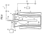
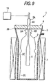
- Figs. 8 and 9 show a fifth embodiment of the invention.
- the coil 6, the matching circuit 17 and the high frequency power source 18 in the first embodiment are therefore omitted.
- the other configuration is the same as that in the first embodiment, and detailed description thereof will be omitted.
- the high voltage power source 15 is also used as a plasma generating unit for generating plasma.
- the surface of the PET container 2 is modified in the following manner.
- the PET container 2 conveyed by a not-shown conveying mechanism is received in the reception chamber 3.
- the cover 4 is moved down to its falling limit position by the elevating mechanism.
- the electrode 5 is inserted into the PET container 2 through the opening portion 2A while the top opening portion of the reception chamber 3 is made airtight by the cover 4 (Fig. 8).
- control unit 14 switches the power source for the solenoid coil 7 so as to make a current flow into the solenoid coil 7 to thereby excite the solenoid coil 7.
- a magnetic field is formed in the reception chamber 3.
- control unit 14 opens the electromagnetic on-off valve 13 for a predetermined period of time.
- the reception chamber 3 is evacuated through the conduit 8 so that the pressure in the internal space of the reception chamber 3 becomes lower than the atmospheric pressure.
- the control unit 14 opens the electromagnetic on-off valve 21 provided in the conduit 16 for a predetermined period of time.
- argon gas is introduced into the internal space of the PET container 2 through the conduit 16. That is, the argon gas intervenes between the spaces inside and outside the PET container 2 in the reception chamber 3. Incidentally, the pressure in the reception chamber 3 at this time is lower than the atmospheric pressure.
- control unit 14 transmits an operating instruction to the DC high voltage power source 15 so that positive high voltage pulses are applied from the high voltage power source 15 to the electrode 5.
- the control unit 14 transmits an operating instruction to the DC high voltage power source 15 so that positive high voltage pulses are applied from the high voltage power source 15 to the electrode 5.
- an operating instruction may be transmitted again to the high voltage power source 15.
- ions are implanted into the interior side surface of the PET container 2 again.
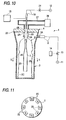
- Figs. 10 and 11 show a sixth embodiment of the invention.
- the solenoid coil 7 in the fourth embodiment shown in Fig. 7 is omitted, and in place of the solenoid coil 7, a plurality of permanent magnets 25 are provided.
- rod-like permanent magnets 25 are disposed at even pitches in the circumferential direction.
- the permanent magnets 25 adjacent to each other are disposed so that the positions of magnetic poles in contact with the inner circumferential surface of the electrode 5 are different from each other.
- a magnetic field is always formed in the electrode 5 itself by the plurality of permanent magnets 25.
- the other configuration is the same as that in the fourth embodiment shown in Fig. 7, and detailed description thereof will be therefore omitted.
- the surface of the PET container 2 is modified in the following manner by the modifying apparatus 1 configured thus according to the sixth embodiment.
- the PET container 2 conveyed by a not-shown conveying mechanism is received in the reception chamber 3.
- the cover 4 and so on are moved down to their falling limit positions by the elevating mechanism.
- the electrode 5 is inserted into the PET container 2 through the opening portion 2A while the top opening portion of the reception chamber 3 is made airtight by the cover 4 (Fig. 10).
- control unit 14 opens the electromagnetic on-off valve 13 for a predetermined period of time.
- the reception chamber 3 is evacuated through the conduit 8 so that the pressure in the internal space of the reception chamber 3 becomes lower than the atmospheric pressure.
- the control unit 14 opens the electromagnetic on-off valve 21 provided in the conduit 16 for a predetermined period of time.
- argon gas is introduced into the internal space of the PET container 2 through the conduit 16. That is, the argon gas intervenes between the spaces inside and outside the PET container 2 in the reception chamber 3.
- the pressure in the reception chamber 3 at this time is not higher than the atmospheric pressure.
- control unit 14 operates the magnetron 26 so that a microwave is supplied from the magnetron 26 toward the cover 4.
- plasma is generated in the argon gas in the reception chamber 3.
- control unit 14 transmits an operating instruction to the DC high voltage power source 15 so that positive high voltage pulses are applied from the high voltage power source 15 to the electrode 5.
- ions in the plasma on the interior side of the PET container 2 are implanted into the PET container 2 from its interior side surface.
- an operating instruction may be transmitted again to the high voltage power source 15.
- ions are implanted into the PET container 2 from its interior side surface again.
- the surface layer of a container made of a polymeric compound can be modified into a material that is not permeable by carbon dioxide gas and oxygen or into a material that is hard to be permeated by carbon dioxide gas and oxygen.
Landscapes
- Chemical & Material Sciences (AREA)
- Chemical Kinetics & Catalysis (AREA)
- Engineering & Computer Science (AREA)
- Organic Chemistry (AREA)
- Materials Engineering (AREA)
- Mechanical Engineering (AREA)
- Metallurgy (AREA)
- Health & Medical Sciences (AREA)
- General Chemical & Material Sciences (AREA)
- Medicinal Chemistry (AREA)
- Polymers & Plastics (AREA)
- Physics & Mathematics (AREA)
- Plasma & Fusion (AREA)
- Analytical Chemistry (AREA)
- Treatments Of Macromolecular Shaped Articles (AREA)
- Plasma Technology (AREA)
- Details Of Rigid Or Semi-Rigid Containers (AREA)
Applications Claiming Priority (2)
| Application Number | Priority Date | Filing Date | Title |
|---|---|---|---|
| JP2001029176 | 2001-02-06 | ||
| JP2001029176A JP3952695B2 (ja) | 2000-05-26 | 2001-02-06 | 高分子化合物製容器の表面改質方法とその装置 |
Publications (2)
| Publication Number | Publication Date |
|---|---|
| EP1229068A1 true EP1229068A1 (fr) | 2002-08-07 |
| EP1229068B1 EP1229068B1 (fr) | 2005-09-14 |
Family
ID=18893553
Family Applications (1)
| Application Number | Title | Priority Date | Filing Date |
|---|---|---|---|
| EP02002554A Expired - Lifetime EP1229068B1 (fr) | 2001-02-06 | 2002-02-04 | Méthode et dispositif pour modifier la surface intérieure de récipients en plastique |
Country Status (3)
| Country | Link |
|---|---|
| US (1) | US20020117114A1 (fr) |
| EP (1) | EP1229068B1 (fr) |
| DE (1) | DE60206084T2 (fr) |
Cited By (4)
| Publication number | Priority date | Publication date | Assignee | Title |
|---|---|---|---|---|
| WO2010095011A1 (fr) | 2009-02-18 | 2010-08-26 | Council Of Scientific & Industrial Research | Procédé pour déposer du carbone de type diamant sous la forme d'un revêtement protecteur sur une surface interne d'un objet façonné |
| EP2799593A4 (fr) * | 2011-12-27 | 2015-08-05 | Kirin Brewery | Appareil permettant de former un film mince |
| US20170062189A1 (en) * | 2015-09-02 | 2017-03-02 | Industrial Technology Research Institute | Apparatus for coating a film in a container and method for coating the film |
| US10259922B2 (en) * | 2013-11-06 | 2019-04-16 | The Board Of Trustees Of The Leland Stanford Junior University | Methods for modifying a hydrophobic polymer surface and devices thereof |
Families Citing this family (24)
| Publication number | Priority date | Publication date | Assignee | Title |
|---|---|---|---|---|
| AU2403001A (en) * | 1999-12-27 | 2001-07-09 | Mitsubishi Shoji Plastics Corporation | Pet container for foods and drinks containing recycled resin and having dlc coating film formed on surface thereof |
| US7618348B2 (en) | 2004-06-21 | 2009-11-17 | Hakooz Joe S | Compact multimode device for low impact therapeutic exercise |
| EP2251453B1 (fr) | 2009-05-13 | 2013-12-11 | SiO2 Medical Products, Inc. | Support de récipient |
| WO2013170052A1 (fr) | 2012-05-09 | 2013-11-14 | Sio2 Medical Products, Inc. | Enrobage protecteur en saccharide pour conditionnement pharmaceutique |
| US9458536B2 (en) | 2009-07-02 | 2016-10-04 | Sio2 Medical Products, Inc. | PECVD coating methods for capped syringes, cartridges and other articles |
| US11624115B2 (en) | 2010-05-12 | 2023-04-11 | Sio2 Medical Products, Inc. | Syringe with PECVD lubrication |
| US9878101B2 (en) | 2010-11-12 | 2018-01-30 | Sio2 Medical Products, Inc. | Cyclic olefin polymer vessels and vessel coating methods |
| US9272095B2 (en) | 2011-04-01 | 2016-03-01 | Sio2 Medical Products, Inc. | Vessels, contact surfaces, and coating and inspection apparatus and methods |
| WO2013071138A1 (fr) | 2011-11-11 | 2013-05-16 | Sio2 Medical Products, Inc. | Revêtement de passivation, de protection de ph ou à pouvoir lubrifiant pour conditionnement pharmaceutique, processus et appareil de revêtement |
| US11116695B2 (en) | 2011-11-11 | 2021-09-14 | Sio2 Medical Products, Inc. | Blood sample collection tube |
| DE102012201955A1 (de) * | 2012-02-09 | 2013-08-14 | Krones Ag | Powerlanze und plasmaunterstützte Beschichtung mit Hochfrequenzeinkopplung |
| US20150297800A1 (en) | 2012-07-03 | 2015-10-22 | Sio2 Medical Products, Inc. | SiOx BARRIER FOR PHARMACEUTICAL PACKAGE AND COATING PROCESS |
| JP6509734B2 (ja) | 2012-11-01 | 2019-05-08 | エスアイオーツー・メディカル・プロダクツ・インコーポレイテッド | 皮膜検査方法 |
| EP2920567B1 (fr) | 2012-11-16 | 2020-08-19 | SiO2 Medical Products, Inc. | Procédé et appareil pour détecter des caractéristiques d'intégrité de revêtement de barrière rapide |
| US9764093B2 (en) | 2012-11-30 | 2017-09-19 | Sio2 Medical Products, Inc. | Controlling the uniformity of PECVD deposition |
| WO2014085348A2 (fr) | 2012-11-30 | 2014-06-05 | Sio2 Medical Products, Inc. | Contrôle de l'uniformité de dépôt chimique en phase vapeur activé par plasma (pecvd) sur des seringues médicales, des cartouches et analogues |
| US9662450B2 (en) | 2013-03-01 | 2017-05-30 | Sio2 Medical Products, Inc. | Plasma or CVD pre-treatment for lubricated pharmaceutical package, coating process and apparatus |
| US9937099B2 (en) | 2013-03-11 | 2018-04-10 | Sio2 Medical Products, Inc. | Trilayer coated pharmaceutical packaging with low oxygen transmission rate |
| KR102167557B1 (ko) | 2013-03-11 | 2020-10-20 | 에스아이오2 메디컬 프로덕츠, 인크. | 코팅된 패키징 |
| US20160017490A1 (en) | 2013-03-15 | 2016-01-21 | Sio2 Medical Products, Inc. | Coating method |
| EP3114250B1 (fr) * | 2014-03-03 | 2024-05-01 | Picosun Oy | Protection de l'intérieur d'un récipient à gaz avec un revêtement formé par dépôt de couches atomiques (ald) |
| EP3122917B1 (fr) | 2014-03-28 | 2020-05-06 | SiO2 Medical Products, Inc. | Revêtements antistatiques pour des récipients en plastique |
| BR112018003051B1 (pt) | 2015-08-18 | 2022-12-06 | Sio2 Medical Products, Inc | Tubo de coleta de sangue submetido a vácuo |
| DE102017108992A1 (de) * | 2017-04-26 | 2018-10-31 | Khs Corpoplast Gmbh | Vorrichtung zur Innenbeschichtung von Behältern |
Citations (5)
| Publication number | Priority date | Publication date | Assignee | Title |
|---|---|---|---|---|
| WO1995022413A1 (fr) * | 1994-02-16 | 1995-08-24 | The Coca-Cola Company | Recipients creux a revetement interieur inerte ou impermeable applique par reaction superficielle au plasma ou polymerisation superficielle |
| EP0773166A1 (fr) * | 1994-08-11 | 1997-05-14 | Kirin Beer Kabushiki Kaisha | Recipient plastique revetu d'un film de carbone |
| WO1999017334A1 (fr) * | 1997-09-30 | 1999-04-08 | Tetra Laval Holdings & Finance S.A. | Procede et appareil pour le traitement de la surface interieure de bouteilles en plastique, dans un procede active par plasma |
| US6001429A (en) * | 1997-08-07 | 1999-12-14 | Becton Dickinson And Company | Apparatus and method for plasma processing |
| US6112695A (en) * | 1996-10-08 | 2000-09-05 | Nano Scale Surface Systems, Inc. | Apparatus for plasma deposition of a thin film onto the interior surface of a container |
Family Cites Families (21)
| Publication number | Priority date | Publication date | Assignee | Title |
|---|---|---|---|---|
| US4667620A (en) * | 1985-10-29 | 1987-05-26 | Cosden Technology, Inc. | Method and apparatus for making plastic containers having decreased gas permeability |
| FR2592874B1 (fr) * | 1986-01-14 | 1990-08-03 | Centre Nat Rech Scient | Procede pour tremper un objet en verre ou vitreux et objet ainsi trempe |
| US4764394A (en) * | 1987-01-20 | 1988-08-16 | Wisconsin Alumni Research Foundation | Method and apparatus for plasma source ion implantation |
| US5578130A (en) * | 1990-12-12 | 1996-11-26 | Semiconductor Energy Laboratory Co., Ltd. | Apparatus and method for depositing a film |
| US5695827A (en) * | 1991-07-01 | 1997-12-09 | Boeing North American, Inc. | Surface protection of gamma and alpha-2 titanium aluminides by ion implantation |
| US5192697A (en) * | 1992-01-27 | 1993-03-09 | Chartered Semiconductor Manufacturing Pte Ltd. | SOG curing by ion implantation |
| US5679412A (en) * | 1993-10-28 | 1997-10-21 | Manfred R. Kuehnle | Method and apparatus for producing gas impermeable, chemically inert container structures for food and volatile substances |
| US5558718A (en) * | 1994-04-08 | 1996-09-24 | The Regents, University Of California | Pulsed source ion implantation apparatus and method |
| GB9412793D0 (en) * | 1994-06-24 | 1994-08-17 | Atomic Energy Authority Uk | Surface treatment of plastic films |
| US5521351A (en) * | 1994-08-30 | 1996-05-28 | Wisconsin Alumni Research Foundation | Method and apparatus for plasma surface treatment of the interior of hollow forms |
| US5952060A (en) * | 1996-06-14 | 1999-09-14 | Applied Materials, Inc. | Use of carbon-based films in extending the lifetime of substrate processing system components |
| JP2856157B2 (ja) * | 1996-07-16 | 1999-02-10 | 日本電気株式会社 | 半導体装置の製造方法 |
| US5707691A (en) * | 1996-08-27 | 1998-01-13 | The Coca-Cola Company | Coating hollow containers by in-situ polymerization of monomers in bi-axially orientated form |
| US5911832A (en) * | 1996-10-10 | 1999-06-15 | Eaton Corporation | Plasma immersion implantation with pulsed anode |
| EP1010773A4 (fr) * | 1997-02-19 | 2004-08-25 | Kirin Brewery | Procede et appareil pour produire un recipient plastique presentant un pelliculage en carbone |
| US6271498B1 (en) * | 1997-06-23 | 2001-08-07 | Nissin Electric Co., Ltd | Apparatus for vaporizing liquid raw material and method of cleaning CVD apparatus |
| WO1999017333A1 (fr) * | 1997-09-30 | 1999-04-08 | Tetra Laval Holdings & Finance S.A. | Dispositif et procede pour le traitement, dans un procede active par plasma, de la surface interieure d'un recipient en plastique presentant une ouverture etroite |
| US6020592A (en) * | 1998-08-03 | 2000-02-01 | Varian Semiconductor Equipment Associates, Inc. | Dose monitor for plasma doping system |
| US6508911B1 (en) * | 1999-08-16 | 2003-01-21 | Applied Materials Inc. | Diamond coated parts in a plasma reactor |
| FR2799994B1 (fr) * | 1999-10-25 | 2002-06-07 | Sidel Sa | Dispositif pour le traitement d'un recipient a l'aide d'un plasma a basse pression comportant un circuit de vide perfectionne |
| US6182604B1 (en) * | 1999-10-27 | 2001-02-06 | Varian Semiconductor Equipment Associates, Inc. | Hollow cathode for plasma doping system |
-
2002
- 2002-02-04 EP EP02002554A patent/EP1229068B1/fr not_active Expired - Lifetime
- 2002-02-04 DE DE60206084T patent/DE60206084T2/de not_active Expired - Lifetime
- 2002-02-05 US US10/062,405 patent/US20020117114A1/en not_active Abandoned
Patent Citations (5)
| Publication number | Priority date | Publication date | Assignee | Title |
|---|---|---|---|---|
| WO1995022413A1 (fr) * | 1994-02-16 | 1995-08-24 | The Coca-Cola Company | Recipients creux a revetement interieur inerte ou impermeable applique par reaction superficielle au plasma ou polymerisation superficielle |
| EP0773166A1 (fr) * | 1994-08-11 | 1997-05-14 | Kirin Beer Kabushiki Kaisha | Recipient plastique revetu d'un film de carbone |
| US6112695A (en) * | 1996-10-08 | 2000-09-05 | Nano Scale Surface Systems, Inc. | Apparatus for plasma deposition of a thin film onto the interior surface of a container |
| US6001429A (en) * | 1997-08-07 | 1999-12-14 | Becton Dickinson And Company | Apparatus and method for plasma processing |
| WO1999017334A1 (fr) * | 1997-09-30 | 1999-04-08 | Tetra Laval Holdings & Finance S.A. | Procede et appareil pour le traitement de la surface interieure de bouteilles en plastique, dans un procede active par plasma |
Cited By (7)
| Publication number | Priority date | Publication date | Assignee | Title |
|---|---|---|---|---|
| WO2010095011A1 (fr) | 2009-02-18 | 2010-08-26 | Council Of Scientific & Industrial Research | Procédé pour déposer du carbone de type diamant sous la forme d'un revêtement protecteur sur une surface interne d'un objet façonné |
| EP2589680A1 (fr) | 2009-02-18 | 2013-05-08 | Council of Scientific & Industrial Research | Dispositif pour déposer du carbone de type diamant comme revêtement protecteur sur une surface interne d'un objet façonné |
| EP2799593A4 (fr) * | 2011-12-27 | 2015-08-05 | Kirin Brewery | Appareil permettant de former un film mince |
| US10259922B2 (en) * | 2013-11-06 | 2019-04-16 | The Board Of Trustees Of The Leland Stanford Junior University | Methods for modifying a hydrophobic polymer surface and devices thereof |
| US20170062189A1 (en) * | 2015-09-02 | 2017-03-02 | Industrial Technology Research Institute | Apparatus for coating a film in a container and method for coating the film |
| CN106480431A (zh) * | 2015-09-02 | 2017-03-08 | 财团法人工业技术研究院 | 容器内部镀膜装置及其方法 |
| US9953809B2 (en) * | 2015-09-02 | 2018-04-24 | Industrial Technology Research Institute | Apparatus for coating a film in a container and method for coating the film |
Also Published As
| Publication number | Publication date |
|---|---|
| US20020117114A1 (en) | 2002-08-29 |
| EP1229068B1 (fr) | 2005-09-14 |
| DE60206084D1 (de) | 2005-10-20 |
| DE60206084T2 (de) | 2006-01-12 |
Similar Documents
| Publication | Publication Date | Title |
|---|---|---|
| EP1229068B1 (fr) | Méthode et dispositif pour modifier la surface intérieure de récipients en plastique | |
| KR100472217B1 (ko) | 저압플라스마를 이용한 용기처리장치용 진공서킷 | |
| US6242053B1 (en) | Process for coating plastic containers or glass containers by means of a PCVD coating process | |
| US6376028B1 (en) | Device and method for treating the inside surface of a plastic container with a narrow opening in a plasma enhanced process | |
| US7926446B2 (en) | Multi-place coating apparatus and process for plasma coating | |
| RU2189401C2 (ru) | Сосуд с покрытием из материала с барьерным эффектом, способ и устройство для его изготовления | |
| RU2199792C2 (ru) | Способ и устройство для плазменной обработки внутренней поверхности пластиковых бутылок | |
| US8062470B2 (en) | Method and apparatus for application of thin coatings from plasma onto inner surfaces of hollow containers | |
| KR100443471B1 (ko) | 플라즈마 처리 방법 | |
| US20130220548A1 (en) | Plasma processing device | |
| JP2000064040A (ja) | 管内面の表面処理方法及び装置 | |
| CN105899240A (zh) | 包括可单独运输的器皿的等离子设备 | |
| JP2004504965A (ja) | バリアコーティング | |
| JP5458253B2 (ja) | プラズマ滅菌装置 | |
| US20220112595A1 (en) | Treatment method and device for depositing a barrier-effect coating | |
| US20050019577A1 (en) | Method of depositing coating by plasma; device for implementing the method and coating obtained by said method | |
| JP3952695B2 (ja) | 高分子化合物製容器の表面改質方法とその装置 | |
| KR20050089516A (ko) | 전자석이 구비된 반도체 식각용 중성빔 소오스 | |
| US7838071B2 (en) | Container-treatment method comprising vacuum pumping phases, and machine for implementing same | |
| KR20100083545A (ko) | 고체 원소 플라즈마 이온주입 방법 및 장치 | |
| WO2005035826A1 (fr) | Appareil de formation de film cvd plasma | |
| US20170077458A1 (en) | Filling apparatus used in an evaporator system and filling method | |
| KR101613432B1 (ko) | 고분자튜브 내면의 표면개질장치 및 이를 이용하는 표면개질방법. | |
| US20250142708A1 (en) | Vacuum Sealed RF Resonator Cavity for LINAC | |
| JP2002339063A (ja) | イオン注入装置 |
Legal Events
| Date | Code | Title | Description |
|---|---|---|---|
| PUAI | Public reference made under article 153(3) epc to a published international application that has entered the european phase |
Free format text: ORIGINAL CODE: 0009012 |
|
| AK | Designated contracting states |
Kind code of ref document: A1 Designated state(s): AT BE CH CY DE DK ES FI FR GB GR IE IT LI LU MC NL PT SE TR |
|
| AX | Request for extension of the european patent |
Free format text: AL;LT;LV;MK;RO;SI |
|
| 17P | Request for examination filed |
Effective date: 20020913 |
|
| 17Q | First examination report despatched |
Effective date: 20021113 |
|
| AKX | Designation fees paid |
Designated state(s): DE FR IT |
|
| GRAP | Despatch of communication of intention to grant a patent |
Free format text: ORIGINAL CODE: EPIDOSNIGR1 |
|
| RIN1 | Information on inventor provided before grant (corrected) |
Inventor name: SAKUDO, NORIYUKI Inventor name: IKENAGA, NORIAKIC/O SHIBUYA KOGYO CO., LTD. |
|
| GRAS | Grant fee paid |
Free format text: ORIGINAL CODE: EPIDOSNIGR3 |
|
| GRAA | (expected) grant |
Free format text: ORIGINAL CODE: 0009210 |
|
| AK | Designated contracting states |
Kind code of ref document: B1 Designated state(s): DE FR IT |
|
| REF | Corresponds to: |
Ref document number: 60206084 Country of ref document: DE Date of ref document: 20051020 Kind code of ref document: P |
|
| ET | Fr: translation filed | ||
| PLBE | No opposition filed within time limit |
Free format text: ORIGINAL CODE: 0009261 |
|
| STAA | Information on the status of an ep patent application or granted ep patent |
Free format text: STATUS: NO OPPOSITION FILED WITHIN TIME LIMIT |
|
| 26N | No opposition filed |
Effective date: 20060615 |
|
| PGFP | Annual fee paid to national office [announced via postgrant information from national office to epo] |
Ref country code: IT Payment date: 20120215 Year of fee payment: 11 |
|
| PGFP | Annual fee paid to national office [announced via postgrant information from national office to epo] |
Ref country code: FR Payment date: 20130301 Year of fee payment: 12 Ref country code: DE Payment date: 20130131 Year of fee payment: 12 |
|
| REG | Reference to a national code |
Ref country code: DE Ref legal event code: R119 Ref document number: 60206084 Country of ref document: DE |
|
| REG | Reference to a national code |
Ref country code: FR Ref legal event code: ST Effective date: 20141031 |
|
| REG | Reference to a national code |
Ref country code: DE Ref legal event code: R119 Ref document number: 60206084 Country of ref document: DE Effective date: 20140902 |
|
| PG25 | Lapsed in a contracting state [announced via postgrant information from national office to epo] |
Ref country code: DE Free format text: LAPSE BECAUSE OF NON-PAYMENT OF DUE FEES Effective date: 20140902 Ref country code: FR Free format text: LAPSE BECAUSE OF NON-PAYMENT OF DUE FEES Effective date: 20140228 |
|
| PG25 | Lapsed in a contracting state [announced via postgrant information from national office to epo] |
Ref country code: IT Free format text: LAPSE BECAUSE OF NON-PAYMENT OF DUE FEES Effective date: 20140204 |