EP1228941A2 - A user-configurable steering control for steer-by-wire systems - Google Patents
A user-configurable steering control for steer-by-wire systems Download PDFInfo
- Publication number
- EP1228941A2 EP1228941A2 EP02075064A EP02075064A EP1228941A2 EP 1228941 A2 EP1228941 A2 EP 1228941A2 EP 02075064 A EP02075064 A EP 02075064A EP 02075064 A EP02075064 A EP 02075064A EP 1228941 A2 EP1228941 A2 EP 1228941A2
- Authority
- EP
- European Patent Office
- Prior art keywords
- signal
- hand wheel
- road wheel
- control system
- configurable
- Prior art date
- Legal status (The legal status is an assumption and is not a legal conclusion. Google has not performed a legal analysis and makes no representation as to the accuracy of the status listed.)
- Withdrawn
Links
- 238000000034 method Methods 0.000 claims description 63
- 238000012937 correction Methods 0.000 claims description 31
- 230000003595 spectral effect Effects 0.000 claims description 15
- 238000006243 chemical reaction Methods 0.000 claims description 4
- 238000004590 computer program Methods 0.000 claims 1
- 238000010586 diagram Methods 0.000 description 7
- 238000001914 filtration Methods 0.000 description 6
- 230000003287 optical effect Effects 0.000 description 4
- 230000008569 process Effects 0.000 description 4
- 230000004044 response Effects 0.000 description 4
- 230000008901 benefit Effects 0.000 description 3
- 238000001514 detection method Methods 0.000 description 3
- 230000001747 exhibiting effect Effects 0.000 description 2
- 239000000835 fiber Substances 0.000 description 2
- 230000004048 modification Effects 0.000 description 2
- 238000012986 modification Methods 0.000 description 2
- 229940083753 renown Drugs 0.000 description 2
- 230000000712 assembly Effects 0.000 description 1
- 238000000429 assembly Methods 0.000 description 1
- 230000005540 biological transmission Effects 0.000 description 1
- 238000004364 calculation method Methods 0.000 description 1
- 238000009429 electrical wiring Methods 0.000 description 1
- 230000005670 electromagnetic radiation Effects 0.000 description 1
- 238000005516 engineering process Methods 0.000 description 1
- 238000012545 processing Methods 0.000 description 1
- 238000006467 substitution reaction Methods 0.000 description 1
- 230000001052 transient effect Effects 0.000 description 1
Images





Classifications
-
- B—PERFORMING OPERATIONS; TRANSPORTING
- B62—LAND VEHICLES FOR TRAVELLING OTHERWISE THAN ON RAILS
- B62D—MOTOR VEHICLES; TRAILERS
- B62D6/00—Arrangements for automatically controlling steering depending on driving conditions sensed and responded to, e.g. control circuits
- B62D6/002—Arrangements for automatically controlling steering depending on driving conditions sensed and responded to, e.g. control circuits computing target steering angles for front or rear wheels
-
- B—PERFORMING OPERATIONS; TRANSPORTING
- B62—LAND VEHICLES FOR TRAVELLING OTHERWISE THAN ON RAILS
- B62D—MOTOR VEHICLES; TRAILERS
- B62D6/00—Arrangements for automatically controlling steering depending on driving conditions sensed and responded to, e.g. control circuits
- B62D6/007—Arrangements for automatically controlling steering depending on driving conditions sensed and responded to, e.g. control circuits adjustable by the driver, e.g. sport mode
-
- B—PERFORMING OPERATIONS; TRANSPORTING
- B62—LAND VEHICLES FOR TRAVELLING OTHERWISE THAN ON RAILS
- B62D—MOTOR VEHICLES; TRAILERS
- B62D6/00—Arrangements for automatically controlling steering depending on driving conditions sensed and responded to, e.g. control circuits
- B62D6/008—Control of feed-back to the steering input member, e.g. simulating road feel in steer-by-wire applications
-
- Y—GENERAL TAGGING OF NEW TECHNOLOGICAL DEVELOPMENTS; GENERAL TAGGING OF CROSS-SECTIONAL TECHNOLOGIES SPANNING OVER SEVERAL SECTIONS OF THE IPC; TECHNICAL SUBJECTS COVERED BY FORMER USPC CROSS-REFERENCE ART COLLECTIONS [XRACs] AND DIGESTS
- Y10—TECHNICAL SUBJECTS COVERED BY FORMER USPC
- Y10S—TECHNICAL SUBJECTS COVERED BY FORMER USPC CROSS-REFERENCE ART COLLECTIONS [XRACs] AND DIGESTS
- Y10S388/00—Electricity: motor control systems
- Y10S388/923—Specific feedback condition or device
- Y10S388/93—Load or torque
Definitions
- Steering equipment for assisting a driver to steer an automobile is well known in the art.
- the operator controls the direction of the vehicle with the aid of a steering wheel.
- This wheel is mechanically connected, usually through a gear assembly to the roadwheels.
- many systems utilize an auxiliary system to generate a force that is transmitted to a steering gear assembly. The additional force reduces the effort required by the operator in changing the direction of the vehicle.
- this auxiliary force is generated by either a hydraulic drive or an electric motor.
- the steering wheel is connected directly to the roadwheels, the resulting mechanical assembly that provides the connection can be quite complicated and expensive to produce.
- One advantage in having a direct connection is that the operator receives tactile feedback through the steering wheel. For example, if the vehicle changes directions while it is moving, the operator will feel resistance in the steering wheel.
- tactile feedback may be provided to the operator by generating feedback forces in a hand wheel system that includes an actuator.
- Two methods have been considered for converting the sensed road forces back to the driver.
- the first method is direct, and simply commands the sensed forces to the Hand Wheel actuator to provide the road resistance to the driver.
- the advantage of this method is that the driver (almost) instantaneously feels the road forces. But, the resulting steering feel to the driver will also be sensitive to changes in the system or component variations.
- the second method also utilizes a road force sensor, but in a feedback loop with a torque sensor signal to generate an error signal.
- the advantage of this method is its insensitivity to variations (and or disturbances) in the hand wheel system.
- the loop gain generally needs to be quite high, thereby making the system potentially prone to instability or susceptible to noise.
- the desired road feel to the operator is commonly very subjective and a function of individual vehicle characteristics and operator taste.
- a steer-by-wire control system comprising a master control system, a road wheel system, and a hand wheel system.
- the road wheel system is connected to the master control system and includes a road wheel position sensor to produce and transmit a road wheel position and a rack force sensor to produce and transmit a rack force signal.
- the hand wheel system is connected to the master control system and the road wheel system and includes a hand wheel position sensor to produce and transmit a hand wheel position signal and a torque sensor to produce and transmit a hand wheel torque signal.
- the steer-by-wire system also includes a vehicle speed sensor for producing a vehicle speed signal, where the vehicle speed sensor is connected to at least one of the master control system, the hand wheel system, and road wheel system.
- a hand wheel actuator configured to receive commands from the hand wheel system and a road wheel actuator configured to receive commands from the road wheel system are utilized.
- the hand wheel system and road wheel system each include a configurable control topology.
- the steer-by-wire control system 10 comprises several closed loop subsystems that work in conjunction to provide an operator with control over the vehicle direction while providing appropriate tactile feedback to the operator.
- the disclosed embodiments may be utilized in various types of vehicles employing electronic steering or steer by wire systems.
- a preferred embodiment, by way of illustration is described herein as it may be applied to an automobile employing a steer by wire system. While a preferred embodiment is shown and described by illustration and reference to an automobile steering system, it will be appreciated by those skilled in the art that the invention is not limited to the automobiles alone by may be applied to other vehicles employing electronic steering systems or steer by wire systems.
- the hand wheel system 14 is a closed loop control system that uses hand wheel torque signal 36 as the feedback to control a hand wheel actuator (not shown).
- the hand wheel system 14 detects the position and movement of a hand wheel (not shown) as made by an operator with a hand wheel position sensor 33 and sends a hand wheel position signal 20 to both the hand wheel system 14 and road wheel system 16.
- the hand wheel position sensor 33 may sense the position based on optical detection, magnetic field variations, or other methodologies. Typical position sensors include potentiometers, resolvers, synchros, encoders, and the like, as well as combinations comprising at least one of the forgoing.
- the hand wheel system 14 utilizes the rack force signals 24 and 26 to generates an equivalent hand wheel torque value 113.
- the equivalent hand wheel torque value 113 is compensated for vehicle speed and summed with a speed compensated, position feedback signal 118 and a hand wheel stability correction 50 to generate a hand wheel reference command signal 120.
- a servo control loop is utilized to track the hand wheel reference command signal 120 and maintain the stability of the hand wheel system 14.
- a hand wheel actuator (not shown) responsive to a hand wheel actuator command signal 136 contains the necessary elements to provide a reaction torque to the operator as well as a torque sensor 31 to provide the measured hand wheel torque signal 36 for the torque feedback loop in the servo control 130 (FIG. 3).
- reaction torque will be imparted to the operator by a hand wheel actuator (e.g., an electric motor) coupled either to the steering column or the rack of the vehicle (not shown) and commanded by the torque servo control 130 (FIG. 3).
- signal connections and interfaces may physically take any form capable of transferring a signal or data, including electrical, optical, or radio, whether digital, modulated, or not and the like, as well as combinations thereof and may include and employ various technologies in implementation, such as wired, wireless, fiber optic, and the like, including combinations thereof.
- look up tables and any filters may take the form of or include multipliers, modulators, schedulers or gains, scaling, and the like, which are configured to be dynamic and may also be the function of other parameters.
- FIG. 3 depicts the hand wheel control system 30 of the hand wheel system 14.
- the hand wheel control system 30 is comprised of two sub-systems: the hand wheel reference command unit 100 and the torque servo control unit 130.
- the hand wheel reference command unit 100 includes a configurable control topology, which includes as inputs rack force signal(s) or their equivalent 24 and 26, as measured by rack force sensor(s) 43 the vehicle speed signal 28, the hand wheel position signal 20 as sensed by hand wheel position sensor 33, and a hand wheel stability correction 50 as calculated by the master control system 12.
- the hand wheel reference command unit 100 provides as an output a hand wheel reference command signal 120, which identifies the desired torque reference for the torque servo control unit 130.
- the torque servo control unit 130 includes as inputs the hand wheel reference command signal 120, and the hand wheel torque signal 36 as sensed by torque sensor 31.
- the rack force signals 24 and 26 are passed through a one or more configurable, frequency based filter(s) 102, which provide the desired frequency characteristics in the resultant force signal 112.
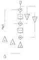
- a typical filter for example, as depicted in FIG. 2 may be employed, where the coefficients of the filter are selected to achieve the desired filtering characteristics.
- a second order filter has been selected because its topology provides the broadest variety of filtering characteristics and yet includes sufficient dynamic capability to capture the desired range of system characteristics. It will be appreciated that a variety of filter designs, topologies and systems may be employed to achieve the prescribed filtering characteristics.
- User configurability provides the flexibility to modify the spectral content of the rack force signals 24, 26. In turn, this allows modification in the frequency range (bandwidth) of the road feedback provided to the driver.
- This feature enables the vehicle original equipment manufacturer (OEM) to tailor and customize the characteristics of the steer-by-system 10 to a variety of vehicle types. For example, an OEM may elect to provide a wide frequency range of response for a very dynamic vehicle, such as a sports car, while at the same time choose to employ a narrower response range for a touring sedan.
- the configurability should be limited and interlocked with respect to the dynamics that can be modified by the OEM to avoid choices that would affect the stability of the steer by wire system 10.
- this concept may be implemented as a set of configurable filter(s) 102 with coefficients selected for modifying the tactile feedback to the operator under different driving conditions. For example, while it is desirable to reduce the road feedback during normal highway driving, it would also be desirable to increase the road feedback under aggressive driving conditions.
- a typical filter for example, as depicted in FIG. 2 may be employed, where the coefficients of the filter are selected to achieve the desired filter characteristics.
- the master control system 12 may then select the appropriate filter.
- a selection means may be implemented to allow an operator to choose between various preset filters.
- the resultant force signal 112 is then scaled as may be required to an equivalent hand wheel torque value 113.
- This scaling is a function of the desired steering ratio and may vary over vehicle applications.
- the equivalent hand wheel torque value 113 is then applied, along with the vehicle speed signal 28 to one or more configurable, torque feed back look-up table(s) 106 to generate a speed compensated, force feedback signal 114.
- user configurability provides the flexibility to modify the steering effort as a function of the vehicle speed. This in turn, provides access to implement customized tuning. This feature once again, enables an OEM to tailor and customize the characteristics of the steer-by-wire system 10 to a variety of vehicle characteristics and types.
- an OEM may elect to utilize proprietary tailoring to yield a vehicle exhibiting characteristics for which that OEM is highly renown.
- the embodiment maybe considered and implemented as a set of configurable lookup tables 106 with tuning chosen to modify the effort based on driver preference. For example, a driver could select between the default steering effort level and sportier feel characteristics.
- a driver selection switch may be implemented to allow the driver to select among the preset tables.
- a second function performed as part of the sub-system hand wheel reference command unit 100 is the calculations based upon hand wheel position.
- the hand wheel position signal 20 is also passed through one or more configurable, frequency based filter(s) 104 (for example, as depicted in FIG. 2), which provides the desired frequency characteristics in the resultant position signal 116.
- user configurability provides OEM the flexibility to modify the spectral content of the position signal. In this instance, this allows the return forces provided to the driver to be modified and characterized as a function of both the hand wheel position and its transient dynamics.
- this embodiment may be considered and implemented as a set of configurable filters with the filter coefficients chosen for modifying the return force dynamic characteristics. Similar to the previously mentioned embodiments, the appropriate filter may then be selected by the master control system 12. Likewise, a driver selection switch capability may be implemented to allow operators to select among the preset filters.
- This resultant position signal 116 is then applied, along with the vehicle speed signal 28 to a configurable, torque return look-up table 108 to generate a speed compensated, position feedback signal 118.
- user configurability provides the flexibility to modify the steering return force characteristics as a function of the vehicle speed. This in turn provides access to implement customized tuning.
- this feature enables an OEM to tailor and customize the characteristics of the steer-by-system 10 to a variety of vehicle characteristics and types. For example, an OEM may elect to utilize proprietary tailoring to yield a vehicle exhibiting characteristics for which that OEM is highly renown. In yet another sense, this may be embodied as a set of configurable lookup tables with tuning chosen to modify the return torque based on driver preference.
- a driver could select between the default steering return and sportier feel characteristics.
- a driver selection switch may be implemented to allow an operator to select among the preset tables.
- the position feedback signal 118 along with the force feedback signal 114 are summed with the hand wheel stability correction 50 at summer 110 to generate the hand wheel reference command signal 120.
- the hand wheel torque servo control unit 130 processing is depicted, where the hand wheel reference command signal 120 is compared with the measured hand wheel torque signal 36, thereby generating a hand wheel torque error signal 132.
- This hand wheel torque error signal 132 is then compensated in a predetermined frequency based compensator 134 to formulate a hand wheel motor command signal, which is applied as a command to the hand wheel actuator.
- This compensation is designed to provide the required stability and performance of the subsystem and is not user configurable.
- the road wheel system 16 is also a closed loop control system that uses a road wheel position signal 44 from a road wheel position sensor 41 as a feedback signal in a closed loop control system command the position of the road wheels of a vehicle.
- the road wheel position sensor 41 may sense the position based on optical detection, magnetic field variations, or other methodologies. Typical position sensors include potentiometers, resolvers, synchros, encoders, and the like, as well as combinations comprising at least one of the forgoing.
- a separate road wheel system 16 is utilized for each steerable wheel. However, for simplicity, a single road wheel system 16 is depicted in the figure.
- a rack force or equivalent sensor 43 is also located within road wheel system 16.
- the rack force signal is then sent to the hand wheel system 12.
- the rack force sensor 43 may sense the forces based on optical detection, magnetic field variations, or other methodologies.
- Typical force sensors include torque bars, strain gauges, deflecting members, potentiometers, resolvers, synchros, encoders, and the like, as well as combinations comprising at least one of the forgoing.
- the road wheel control system 38 of the road wheel system 16 is comprised of two sub-systems: the road wheel reference command unit 200 and the road wheel servo control unit 230.
- the road wheel reference command unit 200 includes a configurable control topology, which includes as inputs the vehicle speed signal 28, the hand wheel position 20 as sensed by hand wheel position sensor 33 of the hand wheel system 14, and a road wheel stability correction 52 as calculated by the master control system 12.
- the road wheel reference command unit 200 provides as an output a road wheel reference command signal 220, which identifies the position reference for the road wheel servo control unit 230.
- the road wheel servo control unit 230 includes as inputs the road wheel reference command signal 220, and a road wheel position signal 44 as sensed by road wheel position sensor 41.
- the road wheel control system 38 employs configurable filters and look up tables to affect the road wheel control.
- a typical filter for example, as depicted in FIG. 2 may be employed, where the coefficients of the filter are selected to achieve the desired filtering characteristics.
- a second order filter has been selected because its topology provides the broadest variety of filtering characteristics and yet includes sufficient dynamic capability to capture the desired range of system characteristics. It will be appreciated that a variety of filter designs, topologies and systems may be employed to achieve the prescribed filtering characteristics.
- the hand wheel position signal 20 is passed through one or more configurable, frequency based filter(s) 202, which provides the desired frequency characteristics in the resultant hand wheel position signal 212.
- the user configurability is to provide the flexibility to modify the spectral content of the position signal 20. This in turn, may be used to control the slew rate and filter the high frequency dynamics of the position signal 20.
- This feature enables the vehicle OEM to tailor and customize the characteristics of the steer-by-system 10 to a variety of vehicle types. For example, an OEM may elect to limit the dynamic slew rate of the hand wheel position signal 20 to limit road wheel system 16 response to high rate inputs and avoid undesirable or unachievable road wheel commands. It is once again, however, noteworthy to appreciate that the configuration should be limited with respect to the dynamics that can be modified by the OEM to avoid choices that would affect the stability of the steer by wire system 10.
- this concept may be implemented as a set of configurable filters with coefficients selected for modifying the dynamics.
- the master control system 12 could then select the appropriate filter.
- a driver selection means may be implemented to allow an operator to choose among the preset filters.
- the resultant hand wheel position signal 212 is then applied, along with the vehicle speed signal 28 to a configurable, variable ratio look-up table 204 to generate a speed compensated steering ratio 214.
- the steering ratio represents the ratio of road wheel position to hand wheel position.
- the variable ratio look-up table 204 allows for variation of the system "gain" as a function of vehicle speed.
- the steer-by-wire system 10 may be dynamically modified to address a variety of driving conditions.
- user configurability provides the flexibility to modify the overall steering ratio as a function of the vehicle speed signal 28. This in turn provides the opportunity to implement customized tuning. This feature enables the vehicle OEM to tailor and customize the characteristics of the steer-by-system 10 to a variety of vehicle types.
- an OEM may elect to provide an OEM proprietary steering ratio.
- Such customization may be embodied and implemented as a set of configurable lookup tables with tuning selected to modify the steering ratio based on driving conditions. For example, it may desirable to increase the steering ratio under aggressive driving conditions. Similarly, it may be desirable to modify the steering ratio to improve high-speed driving characteristics as opposed to those for low speed or parking conditions.
- the master control system 12 may include a selection for the appropriate table. In addition a driver selection switch may be utilized to allow an operator to select between the preset tables.
- the resultant hand wheel position signal 212 and the speed compensated steering ratio 214 are multiplied at multiplier 206 to generate road wheel reference position signal 218.
- the road wheel reference position signal 218 is summed at summer 210 with a road wheel stability correction 52 to generate the road wheel reference command signal 220.
- the road wheel servo control unit 230 where the road wheel reference command signal 220 is compared with the road wheel position signal 44, thereby generating a position error signal 232.
- This position error signal 232 is then compensated in a predetermined frequency based compensator 234 to formulate a road wheel actuator command signal 236 and applied as a command to the road wheel actuator.
- This compensation is designed to provide the required stability and performance of the road wheel control system 38 and is not configurable.
- the disclosed invention may be embodied in the form of computer or processor-implemented processes and apparatuses for practicing those processes.
- the present invention can also be embodied in the form of computer or processor program code containing instructions embodied in tangible media, such as floppy diskettes, CD-ROMs, hard drives, or any other computer-readable storage medium, wherein, when the program code is loaded into and executed by a computer or processor, the computer becomes an apparatus for practicing the invention.
- the present invention can also be embodied in the form of program code, for example, whether stored in a storage medium, loaded into and/or executed by a computer or processor, or as data signal transmitted whether a modulated carrier wave or not, over some transmission medium, such as over electrical wiring or cabling, through fiber optics, or via electromagnetic radiation, wherein, when the program code is loaded into and executed by a computer or processor, the computer or processor becomes an apparatus for practicing the invention.
- program code segments may configure the microprocessor to create specific logic circuits.
Landscapes
- Engineering & Computer Science (AREA)
- Chemical & Material Sciences (AREA)
- Combustion & Propulsion (AREA)
- Transportation (AREA)
- Mechanical Engineering (AREA)
- Physics & Mathematics (AREA)
- Mathematical Physics (AREA)
- Steering Control In Accordance With Driving Conditions (AREA)
Abstract
A steer-by-wire control system (10) comprising a master control
system (12), a road wheel system (16), and a hand wheel system (14) is
disclosed. The road wheel system (16) is connected to the master control
system (12) and includes a road wheel position sensor (41) and a rack force
sensor (43). The hand wheel system (14) is connected to the master control
system (12) and the road wheel system (16) and includes a hand wheel position
sensor (33) and a torque sensor (31). The steer-by-wire system (10) also
includes a vehicle speed sensor (29) for producing a vehicle speed signal (28).
In addition a hand wheel actuator configured to receive commands from the
hand wheel system (14) and a road wheel actuator configured to receive
commands from the road wheel system (16) are utilized. The hand wheel
system (14) and road wheel system (16) each include a configurable control
topology.
Description
- Steering equipment for assisting a driver to steer an automobile is well known in the art. In conventional steering assemblies, the operator controls the direction of the vehicle with the aid of a steering wheel. This wheel is mechanically connected, usually through a gear assembly to the roadwheels. To aid the operator, many systems utilize an auxiliary system to generate a force that is transmitted to a steering gear assembly. The additional force reduces the effort required by the operator in changing the direction of the vehicle. Typically, this auxiliary force is generated by either a hydraulic drive or an electric motor. Because the steering wheel is connected directly to the roadwheels, the resulting mechanical assembly that provides the connection can be quite complicated and expensive to produce. One advantage in having a direct connection is that the operator receives tactile feedback through the steering wheel. For example, if the vehicle changes directions while it is moving, the operator will feel resistance in the steering wheel.
- For Steer-by-wire control systems, tactile feedback may be provided to the operator by generating feedback forces in a hand wheel system that includes an actuator. Two methods have been considered for converting the sensed road forces back to the driver. The first method is direct, and simply commands the sensed forces to the Hand Wheel actuator to provide the road resistance to the driver. The advantage of this method is that the driver (almost) instantaneously feels the road forces. But, the resulting steering feel to the driver will also be sensitive to changes in the system or component variations. The second method also utilizes a road force sensor, but in a feedback loop with a torque sensor signal to generate an error signal. The advantage of this method is its insensitivity to variations (and or disturbances) in the hand wheel system. Unfortunately, to ensure adequate tactile feedback of road forces, the loop gain generally needs to be quite high, thereby making the system potentially prone to instability or susceptible to noise. Moreover, the desired road feel to the operator is commonly very subjective and a function of individual vehicle characteristics and operator taste.
- Therefore, is it considered advantageous to provide a steering control system that provides customizable tactile feedback to the operator allowing for user configurable handling and response characteristics, while maintaining a system that is less sensitive to induced disturbances, but avoids instability and noise susceptibility.
- A steer-by-wire control system comprising a master control system, a road wheel system, and a hand wheel system is disclosed. The road wheel system is connected to the master control system and includes a road wheel position sensor to produce and transmit a road wheel position and a rack force sensor to produce and transmit a rack force signal. The hand wheel system is connected to the master control system and the road wheel system and includes a hand wheel position sensor to produce and transmit a hand wheel position signal and a torque sensor to produce and transmit a hand wheel torque signal. The steer-by-wire system also includes a vehicle speed sensor for producing a vehicle speed signal, where the vehicle speed sensor is connected to at least one of the master control system, the hand wheel system, and road wheel system. In addition a hand wheel actuator configured to receive commands from the hand wheel system and a road wheel actuator configured to receive commands from the road wheel system are utilized. The hand wheel system and road wheel system each include a configurable control topology.
-
- Figure 1a is a block diagram of the steer by wire system;
- Figure 1b is a block diagram illustrating the user configurable steering actuator control algorithm for a steer-by-wire control system;
- Figure 2 is a block diagram of a standard second order digital filter implementation;
- Figure 3 is a block diagram of the hand wheel control system;
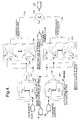
- Figure 4 depicts the process for generating the hand wheel reference command;
- Figure 5 depicts the hand wheel torque servo loop;
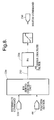
- Figure 6 is a block diagram of the road wheel control system;
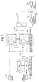
- Figure 7 is a block diagram depicting the process for generating the road wheel reference command; and
- Figure 8 is a block diagram depicting the road wheel servo control loop.
-
- Referring to Figures 1a and 1b, a steering control system is depicted. The steer-by-
wire control system 10 comprises several closed loop subsystems that work in conjunction to provide an operator with control over the vehicle direction while providing appropriate tactile feedback to the operator. - The disclosed embodiments may be utilized in various types of vehicles employing electronic steering or steer by wire systems. A preferred embodiment, by way of illustration is described herein as it may be applied to an automobile employing a steer by wire system. While a preferred embodiment is shown and described by illustration and reference to an automobile steering system, it will be appreciated by those skilled in the art that the invention is not limited to the automobiles alone by may be applied to other vehicles employing electronic steering systems or steer by wire systems.
- The
hand wheel system 14 is a closed loop control system that uses handwheel torque signal 36 as the feedback to control a hand wheel actuator (not shown). Thehand wheel system 14 detects the position and movement of a hand wheel (not shown) as made by an operator with a handwheel position sensor 33 and sends a handwheel position signal 20 to both thehand wheel system 14 androad wheel system 16. The handwheel position sensor 33 may sense the position based on optical detection, magnetic field variations, or other methodologies. Typical position sensors include potentiometers, resolvers, synchros, encoders, and the like, as well as combinations comprising at least one of the forgoing. - The
hand wheel system 14 utilizes the rack force signals 24 and 26 to generates an equivalent handwheel torque value 113. The equivalent handwheel torque value 113 is compensated for vehicle speed and summed with a speed compensated,position feedback signal 118 and a handwheel stability correction 50 to generate a hand wheelreference command signal 120. A servo control loop is utilized to track the hand wheelreference command signal 120 and maintain the stability of thehand wheel system 14. A hand wheel actuator (not shown) responsive to a hand wheelactuator command signal 136 contains the necessary elements to provide a reaction torque to the operator as well as atorque sensor 31 to provide the measured handwheel torque signal 36 for the torque feedback loop in the servo control 130 (FIG. 3). Generally, reaction torque will be imparted to the operator by a hand wheel actuator (e.g., an electric motor) coupled either to the steering column or the rack of the vehicle (not shown) and commanded by the torque servo control 130 (FIG. 3). - Each of the major systems as described may also include additional functions and capabilities not directly relevant to this disclosure, which need not be described herein. Further, as used herein, signal connections and interfaces may physically take any form capable of transferring a signal or data, including electrical, optical, or radio, whether digital, modulated, or not and the like, as well as combinations thereof and may include and employ various technologies in implementation, such as wired, wireless, fiber optic, and the like, including combinations thereof. It will also be appreciated that look up tables and any filters may take the form of or include multipliers, modulators, schedulers or gains, scaling, and the like, which are configured to be dynamic and may also be the function of other parameters.
- In an embodiment, a system and method for user configurable steering control algorithms in a steer-by-
wire system 10 is disclosed. FIG. 3 depicts the handwheel control system 30 of thehand wheel system 14. The handwheel control system 30 is comprised of two sub-systems: the hand wheelreference command unit 100 and the torqueservo control unit 130. The hand wheelreference command unit 100 includes a configurable control topology, which includes as inputs rack force signal(s) or their equivalent 24 and 26, as measured by rack force sensor(s) 43 thevehicle speed signal 28, the handwheel position signal 20 as sensed by handwheel position sensor 33, and a handwheel stability correction 50 as calculated by themaster control system 12. The hand wheelreference command unit 100 provides as an output a hand wheelreference command signal 120, which identifies the desired torque reference for the torqueservo control unit 130. The torqueservo control unit 130 includes as inputs the hand wheelreference command signal 120, and the handwheel torque signal 36 as sensed bytorque sensor 31. - Referring to FIG. 4, the details of the configurable control topology of the hand wheel
reference command unit 100 are depicted. The rack force signals 24 and 26, are passed through a one or more configurable, frequency based filter(s) 102, which provide the desired frequency characteristics in theresultant force signal 112. In an embodiment, a typical filter, for example, as depicted in FIG. 2 may be employed, where the coefficients of the filter are selected to achieve the desired filtering characteristics. A second order filter has been selected because its topology provides the broadest variety of filtering characteristics and yet includes sufficient dynamic capability to capture the desired range of system characteristics. It will be appreciated that a variety of filter designs, topologies and systems may be employed to achieve the prescribed filtering characteristics. User configurability provides the flexibility to modify the spectral content of the rack force signals 24, 26. In turn, this allows modification in the frequency range (bandwidth) of the road feedback provided to the driver. This feature enables the vehicle original equipment manufacturer (OEM) to tailor and customize the characteristics of the steer-by-system 10 to a variety of vehicle types. For example, an OEM may elect to provide a wide frequency range of response for a very dynamic vehicle, such as a sports car, while at the same time choose to employ a narrower response range for a touring sedan. The configurability however, should be limited and interlocked with respect to the dynamics that can be modified by the OEM to avoid choices that would affect the stability of the steer bywire system 10. In a broader sense, this concept may be implemented as a set of configurable filter(s) 102 with coefficients selected for modifying the tactile feedback to the operator under different driving conditions. For example, while it is desirable to reduce the road feedback during normal highway driving, it would also be desirable to increase the road feedback under aggressive driving conditions. Once again, a typical filter, for example, as depicted in FIG. 2 may be employed, where the coefficients of the filter are selected to achieve the desired filter characteristics. Themaster control system 12 may then select the appropriate filter. In addition, a selection means may be implemented to allow an operator to choose between various preset filters. - The
resultant force signal 112 is then scaled as may be required to an equivalent handwheel torque value 113. This scaling is a function of the desired steering ratio and may vary over vehicle applications. The equivalent handwheel torque value 113 is then applied, along with thevehicle speed signal 28 to one or more configurable, torque feed back look-up table(s) 106 to generate a speed compensated,force feedback signal 114. Once again, user configurability provides the flexibility to modify the steering effort as a function of the vehicle speed. This in turn, provides access to implement customized tuning. This feature once again, enables an OEM to tailor and customize the characteristics of the steer-by-wire system 10 to a variety of vehicle characteristics and types. For example, an OEM may elect to utilize proprietary tailoring to yield a vehicle exhibiting characteristics for which that OEM is highly renown. In a broader sense, the embodiment maybe considered and implemented as a set of configurable lookup tables 106 with tuning chosen to modify the effort based on driver preference. For example, a driver could select between the default steering effort level and sportier feel characteristics. A driver selection switch may be implemented to allow the driver to select among the preset tables. - Referring once again to FIG. 4, a second function performed as part of the sub-system hand wheel
reference command unit 100 is the calculations based upon hand wheel position. In a manner similar to the abovementioned embodiment, the handwheel position signal 20 is also passed through one or more configurable, frequency based filter(s) 104 (for example, as depicted in FIG. 2), which provides the desired frequency characteristics in theresultant position signal 116. Once again, user configurability provides OEM the flexibility to modify the spectral content of the position signal. In this instance, this allows the return forces provided to the driver to be modified and characterized as a function of both the hand wheel position and its transient dynamics. In a broader sense, this embodiment may be considered and implemented as a set of configurable filters with the filter coefficients chosen for modifying the return force dynamic characteristics. Similar to the previously mentioned embodiments, the appropriate filter may then be selected by themaster control system 12. Likewise, a driver selection switch capability may be implemented to allow operators to select among the preset filters. - This resultant position signal 116 is then applied, along with the
vehicle speed signal 28 to a configurable, torque return look-up table 108 to generate a speed compensated,position feedback signal 118. Finally, user configurability provides the flexibility to modify the steering return force characteristics as a function of the vehicle speed. This in turn provides access to implement customized tuning. Similarly, this feature enables an OEM to tailor and customize the characteristics of the steer-by-system 10 to a variety of vehicle characteristics and types. For example, an OEM may elect to utilize proprietary tailoring to yield a vehicle exhibiting characteristics for which that OEM is highly renown. In yet another sense, this may be embodied as a set of configurable lookup tables with tuning chosen to modify the return torque based on driver preference. For example, again, a driver could select between the default steering return and sportier feel characteristics. As stated earlier, a driver selection switch may be implemented to allow an operator to select among the preset tables. Theposition feedback signal 118 along with theforce feedback signal 114 are summed with the handwheel stability correction 50 atsummer 110 to generate the hand wheelreference command signal 120. - Referring to FIG. 5, the hand wheel torque
servo control unit 130 processing is depicted, where the hand wheelreference command signal 120 is compared with the measured handwheel torque signal 36, thereby generating a hand wheeltorque error signal 132. This hand wheeltorque error signal 132 is then compensated in a predetermined frequency basedcompensator 134 to formulate a hand wheel motor command signal, which is applied as a command to the hand wheel actuator. This compensation is designed to provide the required stability and performance of the subsystem and is not user configurable. - The
road wheel system 16, as depicted in FIG. 6, is also a closed loop control system that uses a road wheel position signal 44 from a roadwheel position sensor 41 as a feedback signal in a closed loop control system command the position of the road wheels of a vehicle. The roadwheel position sensor 41 may sense the position based on optical detection, magnetic field variations, or other methodologies. Typical position sensors include potentiometers, resolvers, synchros, encoders, and the like, as well as combinations comprising at least one of the forgoing. Typically, a separateroad wheel system 16 is utilized for each steerable wheel. However, for simplicity, a singleroad wheel system 16 is depicted in the figure. A rack force orequivalent sensor 43 is also located withinroad wheel system 16. The rack force signal is then sent to thehand wheel system 12. Therack force sensor 43 may sense the forces based on optical detection, magnetic field variations, or other methodologies. Typical force sensors include torque bars, strain gauges, deflecting members, potentiometers, resolvers, synchros, encoders, and the like, as well as combinations comprising at least one of the forgoing. - The road
wheel control system 38 of theroad wheel system 16 is comprised of two sub-systems: the road wheelreference command unit 200 and the road wheelservo control unit 230. The road wheelreference command unit 200 includes a configurable control topology, which includes as inputs thevehicle speed signal 28, thehand wheel position 20 as sensed by handwheel position sensor 33 of thehand wheel system 14, and a roadwheel stability correction 52 as calculated by themaster control system 12. The road wheelreference command unit 200 provides as an output a road wheelreference command signal 220, which identifies the position reference for the road wheelservo control unit 230. The road wheelservo control unit 230 includes as inputs the road wheelreference command signal 220, and a roadwheel position signal 44 as sensed by roadwheel position sensor 41. - Referring to FIG. 7, similar to the hand
wheel control system 30 the roadwheel control system 38 employs configurable filters and look up tables to affect the road wheel control. In an embodiment, a typical filter, for example, as depicted in FIG. 2 may be employed, where the coefficients of the filter are selected to achieve the desired filtering characteristics. A second order filter has been selected because its topology provides the broadest variety of filtering characteristics and yet includes sufficient dynamic capability to capture the desired range of system characteristics. It will be appreciated that a variety of filter designs, topologies and systems may be employed to achieve the prescribed filtering characteristics. The handwheel position signal 20 is passed through one or more configurable, frequency based filter(s) 202, which provides the desired frequency characteristics in the resultant handwheel position signal 212. The user configurability is to provide the flexibility to modify the spectral content of theposition signal 20. This in turn, may be used to control the slew rate and filter the high frequency dynamics of theposition signal 20. This feature enables the vehicle OEM to tailor and customize the characteristics of the steer-by-system 10 to a variety of vehicle types. For example, an OEM may elect to limit the dynamic slew rate of the handwheel position signal 20 to limitroad wheel system 16 response to high rate inputs and avoid undesirable or unachievable road wheel commands. It is once again, however, noteworthy to appreciate that the configuration should be limited with respect to the dynamics that can be modified by the OEM to avoid choices that would affect the stability of the steer bywire system 10. In a broader sense, this concept may be implemented as a set of configurable filters with coefficients selected for modifying the dynamics. Themaster control system 12 could then select the appropriate filter. In addition, a driver selection means may be implemented to allow an operator to choose among the preset filters. - The resultant hand
wheel position signal 212 is then applied, along with thevehicle speed signal 28 to a configurable, variable ratio look-up table 204 to generate a speed compensatedsteering ratio 214. The steering ratio represents the ratio of road wheel position to hand wheel position. It is noteworthy to appreciate, that the variable ratio look-up table 204 allows for variation of the system "gain" as a function of vehicle speed. Thereby, the steer-by-wire system 10 may be dynamically modified to address a variety of driving conditions. Here again, user configurability provides the flexibility to modify the overall steering ratio as a function of thevehicle speed signal 28. This in turn provides the opportunity to implement customized tuning. This feature enables the vehicle OEM to tailor and customize the characteristics of the steer-by-system 10 to a variety of vehicle types. For example, an OEM may elect to provide an OEM proprietary steering ratio. Such customization may be embodied and implemented as a set of configurable lookup tables with tuning selected to modify the steering ratio based on driving conditions. For example, it may desirable to increase the steering ratio under aggressive driving conditions. Similarly, it may be desirable to modify the steering ratio to improve high-speed driving characteristics as opposed to those for low speed or parking conditions. Themaster control system 12 may include a selection for the appropriate table. In addition a driver selection switch may be utilized to allow an operator to select between the preset tables. - The resultant hand wheel position signal 212 and the speed compensated
steering ratio 214 are multiplied at multiplier 206 to generate road wheelreference position signal 218. The road wheelreference position signal 218 is summed atsummer 210 with a roadwheel stability correction 52 to generate the road wheelreference command signal 220. - Referring to FIG. 8, the road wheel
servo control unit 230 where the road wheelreference command signal 220 is compared with the roadwheel position signal 44, thereby generating aposition error signal 232. Thisposition error signal 232 is then compensated in a predetermined frequency basedcompensator 234 to formulate a road wheelactuator command signal 236 and applied as a command to the road wheel actuator. This compensation is designed to provide the required stability and performance of the roadwheel control system 38 and is not configurable. - It is important to note that all the examples provided herein relate to a vehicle having two steerable wheels. However, this type of system could be easily extended to a vehicle that requires all four wheels to be steered simultaneously by adding a
second roadwheel system 16. - The disclosed invention may be embodied in the form of computer or processor-implemented processes and apparatuses for practicing those processes. The present invention can also be embodied in the form of computer or processor program code containing instructions embodied in tangible media, such as floppy diskettes, CD-ROMs, hard drives, or any other computer-readable storage medium, wherein, when the program code is loaded into and executed by a computer or processor, the computer becomes an apparatus for practicing the invention. The present invention can also be embodied in the form of program code, for example, whether stored in a storage medium, loaded into and/or executed by a computer or processor, or as data signal transmitted whether a modulated carrier wave or not, over some transmission medium, such as over electrical wiring or cabling, through fiber optics, or via electromagnetic radiation, wherein, when the program code is loaded into and executed by a computer or processor, the computer or processor becomes an apparatus for practicing the invention. When implemented on a general-purpose microprocessor, the program code segments may configure the microprocessor to create specific logic circuits.
- While preferred embodiments have been shown and described, various modifications and substitutions may be made thereto without departing from the spirit and scope of the invention. Accordingly, it is to be understood that the present invention has been described by way of illustration only, and such illustrations and embodiments as have been disclosed herein are not to be construed as limiting to the claims.
Claims (91)
- A steer-by-wire control system (10), comprising:wherein said hand wheel system (14) includes a configurable control topology; anda master control system (12);a road wheel system (16) electrically connected to said master control system (12) including a road wheel position sensor (41) to produce and transmit a road wheel position and a rack force sensor (43) to produce and transmit a rack force signal (24), (26);a hand wheel system (14) electrically connected to said master control system (12) and said road wheel system (16) including a hand wheel position sensor (33) to produce and transmit a hand wheel position signal (20), (212) and a torque sensor (31) to produce and transmit a hand wheel torque signal (36);a vehicle speed sensor (29) for producing a vehicle speed signal (28), said vehicle speed sensor electrically connected to at least one of; said master control system (12), said hand wheel system (14), and said road wheel system (16);a hand wheel actuator configured to receive commands from said hand wheel system (14);a road wheel actuator configured to receive commands from said road wheel system (16).
wherein said road wheel system (16) includes a configurable control topology. - A method of steering a vehicle, the method comprising:wherein said hand wheel actuator command signal (136) is the resultant of a configurable control topology; andreceiving a hand wheel stability correction (50);receiving a road wheel stability correction (52);receiving a rack force signal (24), (26) responsive to a measured rack force;receiving a road wheel position signal (44) responsive to a road wheel position;receiving a hand wheel position signal (20) responsive to a hand wheel position;receiving a hand wheel torque signal (36) responsive to a hand wheel torque;receiving a vehicle speed signal (28) responsive to a vehicle speed;generating a hand wheel actuator command signal (136);generating a road wheel actuator command signal (236);
wherein said road wheel actuator command signal (236) is the resultant of a configurable control topology. - A storage medium encoded with a machine-readable computer program code for steering a vehicle, said storage medium including instructions for causing a computer to implement a method comprising:wherein said hand wheel actuator command signal (136) is the resultant of a configurable control topology; andreceiving a hand wheel stability correction (50);receiving a road wheel stability correction (52);receiving a rack force signal (24), (26) responsive to a measured rack force;receiving a road wheel position signal (44) responsive to a road wheel position;receiving a hand wheel position signal (20) responsive to a hand wheel position;receiving a hand wheel torque signal (36) responsive to a hand wheel torque;receiving a vehicle speed signal (28) responsive to a vehicle speed;generating a hand wheel actuator command signal (136);generating a road wheel actuator command signal (236);
wherein said road wheel actuator command signal (236) is the resultant of a configurable control topology. - A computer data signal for steering a vehicle, said computer data signal comprising code configured to cause a computer to implement a method comprising:wherein said hand wheel actuator command signal (136) is the resultant of a configurable control topology; andreceiving a hand wheel stability correction (50);receiving a road wheel stability correction (52);receiving a rack force signal (24), (26) responsive to a measured rack force;receiving a road wheel position signal (44) responsive to a road wheel position;receiving a hand wheel position signal (20) responsive to a hand wheel position;receiving a hand wheel torque signal (36) responsive to a hand wheel torque;receiving a vehicle speed signal (28) responsive to a vehicle speed;generating a hand wheel actuator command signal (136);generating a road wheel actuator command signal (236);
wherein said road wheel actuator command signal (236) is the resultant of a configurable control topology. - The steer-by-wire control system (10) of Claim 1 wherein said master control system (12) calculates a hand wheel stability correction (50) and a road wheel stability correction (52).
- The steer-by-wire control system (10) of Claim 5 wherein said hand wheel system (14) comprises a closed loop control system responsive to at least one of said hand wheel torque signal (36), said rack force signal (24), (26), said vehicle speed signal (28), said hand wheel position signal (20) and said hand wheel stability correction (50).
- The steer-by-wire control system (10) of Claim 5 wherein said hand wheel system (14) comprises a hand wheel reference command unit (100) and a torque servo control unit (130).
- The steer-by-wire control system (10) of Claim 7 wherein:said hand wheel reference command unit (100) is responsive to said rack force signal (24), (26), said vehicle speed signal (28), said hand wheel position signal (20) and said hand wheel stability correction (50) and generates a hand wheel reference command signal (120); andsaid torque servo control unit (130) is responsive to said hand wheel torque signal and said hand wheel reference command signal (120) to provide a command to said hand wheel actuator wherein said hand wheel actuator is configured to position a hand wheel thereby generating a reaction torque.
- The steer-by-wire control system (10) of Claim 9 wherein said torque servo control unit includes a frequency based compensator (134), (234) configured to characterize spectral content of at least one of said hand wheel reference command signal (120) and said hand wheel torque signal (36) to maintain stability of said hand wheel system (14).
- The steer-by-wire control system (10) of Claim 8 wherein said hand wheel system (14) includes a configurable frequency based filter (102) configured to characterize spectral content of said rack force signal (24), (26) to increase bandwidth of said hand wheel system (14).
- The steer-by-wire control system (10) of Claim 10 wherein said configurable frequency based filter (102) comprises a user configurable filter.
- The steer-by-wire control system (10) of Claim 10 wherein said configurable frequency based filter (102) comprises a second order discrete filter.
- The steer-by-wire control system (10) of Claim 8 wherein said hand wheel system (14) includes a configurable frequency based filter (104) configured to characterize spectral content of said hand wheel position to control return force dynamic characteristics of said hand wheel system (14).
- The steer-by-wire control system (10) of Claim 13 wherein said configurable frequency based filter (104) comprises a user configurable filter.
- The steer-by-wire control system (10) of Claim 1 3 wherein said configurable frequency based filter (104) comprises a second order discrete filter.
- The steer-by-wire control system (10) of Claim 13 wherein said hand wheel system (14) includes another configurable frequency based filter (102) configured to characterize spectral content of said rack force signal (24), (26) to increase bandwidth of said hand wheel system (14).
- The steer-by-wire control system (10) of Claim 16 wherein said another configurable frequency based filter (102) comprises a user configurable filter.
- The steer-by-wire control system (10) of Claim 16 wherein said another configurable frequency based filter (102) comprises a second order discrete filter.
- The steer-by-wire control system (10) of Claim 16 wherein said hand wheel reference command signal (120) results from a summation including a hand wheel stability correction (50), a force feedback signal (114), and a position feed back signal (118).
- The steer-by-wire control system (10) of Claim 19 wherein said force feedback signal (114) results from a torque feed back look up table (106) responsive to said vehicle speed signal (28) and a resultant force signal (112).
- The steer-by-wire control system (10) of Claim 8 wherein said hand wheel reference command signal (120) results from a summation including a hand wheel stability correction (50), a force feedback signal (114), and a position feed back signal (118).
- The steer-by-wire control system (10) of Claim 19 wherein said force feedback signal (114) results from a torque feed back look up table (106) responsive to said vehicle speed signal (28) and a resultant force signal (112).
- The steer-by-wire control system (10) of Claim 22 wherein said torque feed back look up table (106) is user configurable.
- The steer-by-wire control system (10) of Claim 22 wherein said resultant force signal (112) comprises a resultant from a configurable frequency based filter (102) responsive to said rack force signal (24), (26).
- The steer-by-wire control system (10) of Claim 24 wherein said configurable frequency based filter (102) is user configurable.
- The steer-by-wire control system (10) of Claim 22 wherein said position feed back signal (118) results from a torque return look up table (108) responsive to said vehicle speed signal (28) and a resultant position signal (116).
- The steer-by-wire control system (10) of Claim 26 wherein said torque return look up table (108) is user configurable.
- The steer-by-wire control system (10) of Claim 26 wherein said resultant position signal (116) results from another configurable frequency based filter (104) responsive to said hand wheel position signal (20).
- The steer-by-wire control system (10) of Claim 26 wherein said another configurable frequency based filter (104) is user configurable.
- The steer-by-wire control system (10) of Claim 5 wherein said road wheel system (16) comprises a closed loop control system responsive to at least one of said hand wheel position signal (20), said vehicle speed signal (28), said road wheel stability correction (52), said road wheel position.
- The steer-by-wire control system (10) of Claim 5 wherein said road wheel system (16) comprises a road wheel reference command unit (200) and a road wheel servo control unit (230).
- The steer-by-wire control system (10) of Claim 31 wherein:said road wheel reference command unit (200) is responsive to said hand wheel position signal (20), said vehicle speed signal (28), and said road wheel stability correction (52) and generates a road wheel reference command signal (220); and,said road wheel servo control unit (230) is responsive to said road wheel position and said road wheel reference command signal (220) to provide a road wheel command to said road wheel actuator wherein said road wheel actuator is configured to position a road wheel.
- The steer-by-wire control system (10) of Claim 32 wherein said road wheel servo control unit (230) includes a frequency based compensator (134), (234) configured to characterize spectral content of at least one of said road wheel reference command signal (220) and said hand wheel torque signal (36) to maintain stability of said road wheel system (16).
- The steer-by-wire control system (10) of Claim 32 wherein said road wheel system (16) includes a configurable frequency based filter (202) configured to characterize spectral content of said hand wheel position to constrain bandwidth of hand wheel inputs to said hand wheel system (14).
- The steer-by-wire control system (10) of Claim 34 wherein said configurable frequency based filter (202) comprises a user configurable filter.
- The steer-by-wire control system (10) of Claim 34 wherein said configurable frequency based filter (202) comprises a second order discrete filter.
- The steer-by-wire control system (10) of Claim 32 wherein said road wheel command is a resultant of a frequency based compensator (134), (234) applied to a road wheel position error signal (232).
- The steer-by-wire control system (10) of Claim 37 wherein said road wheel position error signal (232) results from a difference of said road wheel reference command signal (220) and said road wheel position.
- The steer-by-wire control system (10) of Claim 38 wherein said road wheel reference command signal (220) results from a summation of a road wheel stability correction (52) and a road wheel reference position signal (218).
- The steer-by-wire control system (10) of Claim 39 wherein said road wheel reference position signal (218) results from a multiplication of a speed compensated steering ratio (214) and a resultant hand wheel position signal (212).
- The steer-by-wire control system (10) of Claim 40 wherein said speed compensated steering ratio (214) results from a variable ratio look up table (204), responsive to said vehicle speed signal (28) and said hand wheel position signal (20).
- The steer-by-wire control system (10) of Claim 40 wherein said variable ratio, look up table is configurable.
- The steer-by-wire control system (10) of Claim 41 wherein said resultant hand wheel position signal (212) results from a configurable frequency based filter (202) responsive to said hand wheel position signal (20).
- The steer-by-wire control system (10) of Claim 43 wherein said configurable frequency based filter (202) is user configurable.
- The steer-by-wire control system (10) of Claim 1 wherein said configurable control topology comprises at least one of; a configurable frequency based filter (102), (104), (202), a look up table (106), (108), (204), which is user configurable.
- The method of Claim 2 wherein said hand wheel actuator command signal (136) is responsive to said hand wheel torque signal (36), said hand wheel position signal (20), said hand wheel stability correction (50), and said vehicle speed signal (28).
- The method of Claim 46 wherein said rack force signal (24), (26) and a road wheel position signal (44) are produced in a road wheel system (16) electrically connected to a master control system (12).
- The method of Claim 2 wherein said road wheel actuator command signal (236) is responsive to said hand wheel position signal (20), said road wheel stability correction (52), and said vehicle speed signal (28).
- The method of Claim 48 wherein said hand wheel position signal (20) and a hand wheel torque signal (36) are produced in a hand wheel system (14) electrically connected to a master control system (12).
- The method of Claim 2 wherein said vehicle speed signal (28) is produced with a vehicle speed sensor (29) electrically connected to a master control system (12) and a hand wheel system (14).
- The method of Claim 2 wherein said hand wheel stability correction (50) and a road wheel stability correction (52) are calculated in a master control system (12).
- The method of Claim 49 wherein said hand wheel system (14) comprises a closed loop control system responsive to at least one of said hand wheel torque signal, said rack force signal (24), (26), said vehicle speed signal (28), said hand wheel position signal (20) and said hand wheel stability correction (50).
- The method of Claim 49 wherein said hand wheel system (14) comprises a hand wheel reference command unit (100) and a torque servo control unit (130).
- The method of Claim 53 further including:generating a hand wheel reference command signal (120) in said hand wheel reference command unit (100), responsive to said rack force signal (24), (26), said vehicle speed signal (28), said hand wheel position signal (20) and said hand wheel stability correction (50); and,providing said hand wheel actuator command signal (136) to said hand wheel actuator from said torque servo control unit (130), said hand wheel actuator command signal (136) responsive to said hand wheel torque signal (36) and said hand wheel reference command signal (120), and wherein said hand wheel actuator is configured to position a hand wheel thereby generating a reaction torque.
- The method of Claim 54 wherein said providing includes characterizing spectral content of at least one of said hand wheel reference command signal (120) and said hand wheel torque signal (36) with a frequency based compensator (134) torque servo control system configured to maintain stability of said hand wheel system (14).
- The method of Claim 54 wherein said providing includes characterizing spectral content of said rack force signal (24), (26) with a configurable frequency based filter (102) configured to increase bandwidth of said hand wheel system (14).
- The method of Claim 56 wherein said configurable frequency based filter (102) comprises a user configurable filter.
- The method of Claim 56 wherein said configurable frequency based filter (102) comprises a second order discrete filter.
- The method of Claim 54 wherein said providing includes characterizing spectral content of said hand wheel position signal (20) with a configurable frequency based filter (104) configured to control return force dynamic characteristics of said hand wheel system (14).
- The method of Claim 59 wherein said configurable frequency based filter (104) comprises a user configurable filter.
- The method of Claim 60 wherein said configurable frequency based filter (104) comprises a second order discrete filter.
- The method of Claim 59 wherein said providing includes characterizing spectral content of said rack force signal (24), (26) with another configurable frequency based filter (102) configured to increase bandwidth of said hand wheel system (14).
- The method of Claim 62 wherein said another configurable frequency based filter (102) comprises a user configurable filter.
- The method of Claim 62 wherein said another configurable frequency based filter (102) comprises a second order discrete filter.
- The method of Claim 62 wherein said hand wheel reference command signal (120) results from a summation including a hand wheel stability correction (50), a force feedback signal (114), and a position feed back signal (118).
- The method of Claim 65 wherein said force feedback signal (114) results from a torque feed back look up table (106) responsive to said vehicle speed signal (28) and a resultant force signal (112).
- The method of Claim 54 wherein said hand wheel reference command signal (120) results from a summation including a hand wheel stability correction (50), a force feedback signal (114), and a position feed back signal (118).
- The method of Claim 65 wherein said force feedback signal (114) results from a torque feed back look up table (106) responsive to said vehicle speed signal (28) and a resultant force signal (112).
- The method of Claim 68 wherein said torque feed back look up table (106) is user configurable.
- The method of Claim 68 wherein said resultant force signal (112) comprises a resultant from a configurable frequency based filter (102) responsive to said rack force signal (24), (26).
- The method of Claim 70 wherein said configurable frequency based filter (102) is user configurable.
- The method of Claim 68 wherein said position feed back signal (118) results from a torque return look up table (108) responsive to said vehicle speed signal (28) and a resultant position signal (116).
- The method of Claim 72 wherein said torque return look up table (108) is user configurable.
- The method of Claim 72 wherein said resultant position signal (116) results from another configurable frequency based filter (104) responsive to said hand wheel position signal (20).
- The method of Claim 74 wherein said another configurable frequency based filter (104) is user configurable.
- The method of Claim 47 wherein said road wheel system (16) comprises a closed loop control system responsive to at least one of said hand wheel position signal (20), said vehicle speed signal (28), said road wheel stability correction (52), said road wheel position signal (44).
- The method of Claim 47 wherein said road wheel system (16) comprises a road wheel reference command unit (200) and a road wheel servo control unit (230).
- The method of Claim 77 further including:generating a road wheel reference command signal (220) in said road wheel reference command unit (200), responsive to said hand wheel position signal (20), (212), said vehicle speed signal (28), and said road wheel stability correction (52); and,providing said a road wheel actuator command signal (236) to said road wheel actuator from said road wheel servo control unit (230), said road wheel actuator command signal (236) responsive to said road wheel position signal (44) and said road wheel reference command signal (220), and wherein said road wheel actuator configured to position a road wheel.
- The method of Claim 78 wherein said providing includes characterizing spectral content of at least one of said road wheel reference command signal (220) and said hand wheel torque signal (36) with a frequency based compensator (234) configured to maintain stability of said road wheel system (16).
- The method of Claim 78 wherein said providing includes characterizing spectral content of said hand wheel position signal (20) with a configurable frequency based filter (104) configured to constrain bandwidth of hand wheel inputs to said road wheel system (16).
- The method of Claim 80 wherein said configurable frequency based filter (104) comprises a user configurable filter.
- The method of Claim 80 wherein said configurable frequency based filter (104) comprises a second order discrete filter.
- The method of Claim 78 wherein said road wheel actuator command signal (236) is a resultant of a frequency based compensator (134), (234) applied to a road wheel position error signal (232).
- The method of Claim 83 wherein said road wheel position error signal (232) results from a difference of said road wheel reference command signal (220) and said road wheel position signal (44).
- The method of Claim 84 wherein said road wheel reference command signal (220) results from a summation of a road wheel stability correction (52) and a road wheel position reference position signal (218).
- The method of Claim 85 wherein said road wheel reference position signal (218) results from a multiplication of a speed compensated steering ratio (214) and a resultant hand wheel position signal (212).
- The method of Claim 86 wherein said speed compensated steering ratio (214) results from a variable ratio look up table (204), responsive to said vehicle speed signal (28) and said hand wheel position signal (212).
- The method of Claim 86 wherein said variable ratio look up table (204) is configurable.
- The method of Claim 87 wherein said resultant hand wheel position signal (212) results from a configurable frequency based filter (202) responsive to said hand wheel position signal (20).
- The method of Claim 89 wherein said configurable frequency based filter (202) is user configurable.
- The method of Claim 2 wherein said configurable control topology comprises at least one of; a configurable frequency based filter (102), (104), (202), a look up table (106), (108), (204), which is user configurable.
Applications Claiming Priority (2)
| Application Number | Priority Date | Filing Date | Title |
|---|---|---|---|
| US775880 | 1991-10-11 | ||
| US09/775,880 US6678594B2 (en) | 2001-02-02 | 2001-02-02 | User-configurable steering control for steer-by-wire systems |
Publications (1)
| Publication Number | Publication Date |
|---|---|
| EP1228941A2 true EP1228941A2 (en) | 2002-08-07 |
Family
ID=25105820
Family Applications (1)
| Application Number | Title | Priority Date | Filing Date |
|---|---|---|---|
| EP02075064A Withdrawn EP1228941A2 (en) | 2001-02-02 | 2002-01-08 | A user-configurable steering control for steer-by-wire systems |
Country Status (2)
| Country | Link |
|---|---|
| US (1) | US6678594B2 (en) |
| EP (1) | EP1228941A2 (en) |
Cited By (6)
| Publication number | Priority date | Publication date | Assignee | Title |
|---|---|---|---|---|
| EP1600359A3 (en) * | 2004-05-27 | 2006-03-01 | Nissan Motor Company, Limited | Vehicle steering apparatus and method |
| US7581616B2 (en) | 2004-01-07 | 2009-09-01 | Toyota Jidosha Kobushiki Kaisha | Control system for a steer-by-wire vehicle |
| CN103496394A (en) * | 2013-10-09 | 2014-01-08 | 浙江达世元电动科技有限公司 | Electric steering system and electric steering control method of new energy automobile |
| WO2017135884A1 (en) | 2016-02-05 | 2017-08-10 | Sentient Sweden Ekonomisk Förening | Method for the control of vehicle steering and vehicle behaviour |
| US12344340B2 (en) | 2019-10-13 | 2025-07-01 | Sentient Ab | Method and system arrangement for vehicle steering and vehicle with such a system |
| US12662108B2 (en) | 2022-07-18 | 2026-06-23 | Sentient Ab | System and method for vehicle motion control |
Families Citing this family (28)
| Publication number | Priority date | Publication date | Assignee | Title |
|---|---|---|---|---|
| US20030037982A1 (en) * | 2001-08-23 | 2003-02-27 | Chernoff Adrian B. | Vehicle chassis having programmable operating characteristics and method for using same |
| US6687588B2 (en) | 2001-09-14 | 2004-02-03 | Delphi Technologies, Inc. | Compensation using position for improved feel and stability in a steering system |
| US20030150366A1 (en) | 2002-02-13 | 2003-08-14 | Kaufmann Timothy W. | Watercraft steer-by-wire system |
| US7212896B2 (en) * | 2002-05-29 | 2007-05-01 | Ford Global Technologies, Llc | Vehicle control |
| US6926114B2 (en) * | 2002-06-03 | 2005-08-09 | Delphi Technologies, Inc. | Assist modification in active front steering |
| US7083025B2 (en) * | 2002-06-03 | 2006-08-01 | Delphi Technologies, Inc. | Method for implementing vehicle stability enhancement reference models for active steer systems |
| EP1431160B1 (en) * | 2002-12-20 | 2006-07-26 | Ford Global Technologies, LLC | Control strategy for computer-controlled steering |
| US20040189228A1 (en) * | 2003-03-28 | 2004-09-30 | Gregory Katch | Vehicle speed dependent compensator for electric steering systems |
| US6732979B1 (en) | 2003-08-28 | 2004-05-11 | The Boeing Company | Steer-by-wire tiller with position feel system |
| US7530422B2 (en) * | 2004-09-17 | 2009-05-12 | Delphi Technologies, Inc. | Force and position control for active front steering |
| US20060200291A1 (en) * | 2005-03-07 | 2006-09-07 | Wroblewski Anthony J | Tactile electronic steering system |
| US9199667B2 (en) | 2014-03-14 | 2015-12-01 | Mitsubishi Electric Research Laboratories, Inc. | System and method for semi-autonomous driving of vehicles |
| US9845109B2 (en) * | 2015-03-25 | 2017-12-19 | Steering Solutions Ip Holding Corporation | Continuous estimation of surface friction coefficient based on EPS and vehicle models |
| US10399597B2 (en) | 2015-10-09 | 2019-09-03 | Steering Solutions Ip Holding Corporation | Payload estimation using electric power steering signals |
| EP3178724B1 (en) * | 2015-12-08 | 2018-10-24 | Volvo Car Corporation | Vehicle steering arrangement, autonomous vehicle steering arrangement, a vehicle, and a method of steering a vehicle |
| KR101765556B1 (en) * | 2016-05-11 | 2017-08-23 | (주)캠시스 | Apparatus and method for processing the image according to the velocity of automobile |
| GB2550350B (en) * | 2016-05-16 | 2019-10-09 | Jaguar Land Rover Ltd | Wireless control system for a vehicle |
| DE102017115850B4 (en) * | 2017-07-14 | 2021-03-04 | Thyssenkrupp Ag | Steer-by-wire steering system with adaptive rack position control |
| US10661829B2 (en) * | 2018-06-08 | 2020-05-26 | GM Global Technology Operations LLC | Performance active and adaptive steering response and feel in real-time for steer-by-wire vehicle |
| US10676129B2 (en) * | 2018-06-25 | 2020-06-09 | Steering Solutions Ip Holding Corporation | Driver notification using handwheel actuators in steer-by-wire systems |
| US11511790B2 (en) | 2019-02-14 | 2022-11-29 | Steering Solutions Ip Holding Corporation | Road friction coefficient estimation using steering system signals |
| US11498613B2 (en) | 2019-02-14 | 2022-11-15 | Steering Solutions Ip Holding Corporation | Road friction coefficient estimation using steering system signals |
| KR102745128B1 (en) * | 2019-11-01 | 2024-12-23 | 현대모비스 주식회사 | Steer-by-wire system and operation method thereof |
| DE102021100623B4 (en) * | 2020-01-17 | 2023-08-24 | Steering Solutions Ip Holding Corporation | EXPENDITURE FOR A VERSATILE DRIVING FEELING |
| KR20220001205A (en) * | 2020-06-29 | 2022-01-05 | 주식회사 만도 | Method and Apparatus for Generating Steering Wheel Reaction Torque Signal in SBW system, and SBW Steering System with the same |
| GB2604321B (en) * | 2020-12-31 | 2024-12-25 | Zf Automotive Uk Ltd | Steer by wire system for an automotive vehicle |
| US11052940B1 (en) | 2021-03-12 | 2021-07-06 | Canoo Technologies Inc. | Steer-by-wire systems and methods of operating thereof in vehicles |
| JP7706006B2 (en) * | 2022-02-15 | 2025-07-10 | Astemo株式会社 | Vehicle control device |
Family Cites Families (37)
| Publication number | Priority date | Publication date | Assignee | Title |
|---|---|---|---|---|
| JPS60259570A (en) | 1984-06-04 | 1985-12-21 | Kayaba Ind Co Ltd | Power steering apparatus operated by electric motor |
| US4800974A (en) * | 1985-10-23 | 1989-01-31 | Trw Inc. | Electric steering gear |
| EP0278366B1 (en) | 1987-02-03 | 1991-03-06 | Kabushiki Kaisha Toyota Chuo Kenkyusho | Apparatus for controlling steering of wheels of a vehicle |
| JPH01115778A (en) | 1987-10-30 | 1989-05-09 | Jidosha Kiki Co Ltd | Rear wheel steering device for four-wheel steering car |
| US4860844A (en) | 1988-04-29 | 1989-08-29 | Eaton Corporation | Power steering system |
| JP2762711B2 (en) | 1990-07-02 | 1998-06-04 | 日産自動車株式会社 | Vehicle braking behavior compensator |
| JPH04133861A (en) * | 1990-09-25 | 1992-05-07 | Honda Motor Co Ltd | Control method for vehicle steering device |
| JPH04133860A (en) | 1990-09-25 | 1992-05-07 | Honda Motor Co Ltd | Control method for vehicle steering device |
| JPH05105100A (en) | 1991-09-27 | 1993-04-27 | Honda Motor Co Ltd | Vehicle steering system |
| US5257828A (en) * | 1992-06-03 | 1993-11-02 | Trw Inc. | Method and apparatus for controlling damping in an electric assist steering system for vehicle yaw rate control |
| JPH0662508A (en) | 1992-08-05 | 1994-03-04 | Nissan Motor Co Ltd | Method and apparatus for controlling power of electric vehicle |
| JP3229077B2 (en) | 1993-06-29 | 2001-11-12 | 本田技研工業株式会社 | Vehicle steering system |
| JP2686042B2 (en) | 1994-03-02 | 1997-12-08 | 本田技研工業株式会社 | Control device for front and rear wheel steering vehicles |
| US5653304A (en) | 1994-04-20 | 1997-08-05 | University Of Arkansas, N.A. | Lever steering system |
| JP3216441B2 (en) | 1994-05-18 | 2001-10-09 | トヨタ自動車株式会社 | Vehicle steering system |
| US5475289A (en) * | 1994-11-04 | 1995-12-12 | Trw Inc. | Method and apparatus for controlling an electric assist steering system using two-dimensional interpolation for current commands |
| JP3133914B2 (en) | 1994-12-21 | 2001-02-13 | 三菱電機株式会社 | Electric power steering device |
| JPH0920263A (en) | 1995-07-06 | 1997-01-21 | Jidosha Kiki Co Ltd | Electric pump type power steering device |
| US5668722A (en) * | 1995-10-02 | 1997-09-16 | General Motors Corporation | Electric power steering control |
| DE19540956C1 (en) | 1995-11-03 | 1997-03-06 | Daimler Benz Ag | Servo-assisted steering for motor vehicle |
| DE19632251B4 (en) | 1996-08-09 | 2004-08-26 | Volkswagen Ag | Device and method for steering a motor vehicle |
| DE19650691C2 (en) | 1996-12-07 | 1998-10-29 | Deutsch Zentr Luft & Raumfahrt | Method for steering assistance for a driver of a road vehicle |
| JP4026887B2 (en) | 1997-07-24 | 2007-12-26 | 本田技研工業株式会社 | Electric power steering device |
| US6097286A (en) | 1997-09-30 | 2000-08-01 | Reliance Electric Technologies, Llc | Steer by wire system with feedback |
| US6081484A (en) | 1997-10-14 | 2000-06-27 | Schlumberger Technologies, Inc. | Measuring signals in a tester system |
| US6152254A (en) | 1998-06-23 | 2000-11-28 | Techco Corporation | Feedback and servo control for electric power steering system with hydraulic transmission |
| DE19834870A1 (en) | 1998-08-01 | 2000-02-03 | Bosch Gmbh Robert | Steering adjuster with electric motor, especially for steer-by-wire use in cars has steering adjuster divided into two diversely redundant systems and control system with two diversely |
| DE19839953C2 (en) | 1998-09-02 | 2000-06-21 | Daimler Chrysler Ag | Steering system for non-track-bound motor vehicles |
| US6209677B1 (en) | 1998-09-09 | 2001-04-03 | Daimlerchrysler Ag | Steering system for non-tracked motor vehicles |
| DE19842627A1 (en) * | 1998-09-17 | 2000-04-06 | Daimler Chrysler Ag | Steering system for a vehicle |
| GB2341587B (en) | 1998-09-17 | 2000-12-06 | Daimler Chrysler Ag | Method for operating a steering system for a vehicle |
| JP3648392B2 (en) * | 1998-09-18 | 2005-05-18 | 光洋精工株式会社 | Power steering device |
| US6179394B1 (en) | 1998-11-09 | 2001-01-30 | General Motors Corporation | Active brake balance control method |
| US6098296A (en) | 1998-12-03 | 2000-08-08 | Delco Electronics Corp. | Wheel alignment system and method for vehicles having steer-by-wire steering system |
| AU1843100A (en) | 1998-12-09 | 2000-06-26 | Delphi Technologies, Inc. | A vehicle steering command module having a reconfigurable instrument gauge display |
| JP2000198453A (en) * | 1998-12-29 | 2000-07-18 | Robert Bosch Gmbh | Vehicle steer-by-wire steering system |
| US6176341B1 (en) * | 1999-02-01 | 2001-01-23 | Delphi Technologies, Inc. | Vehicle steering system having master/slave configuration and method therefor |
-
2001
- 2001-02-02 US US09/775,880 patent/US6678594B2/en not_active Expired - Lifetime
-
2002
- 2002-01-08 EP EP02075064A patent/EP1228941A2/en not_active Withdrawn
Non-Patent Citations (1)
| Title |
|---|
| None |
Cited By (9)
| Publication number | Priority date | Publication date | Assignee | Title |
|---|---|---|---|---|
| US7581616B2 (en) | 2004-01-07 | 2009-09-01 | Toyota Jidosha Kobushiki Kaisha | Control system for a steer-by-wire vehicle |
| EP1600359A3 (en) * | 2004-05-27 | 2006-03-01 | Nissan Motor Company, Limited | Vehicle steering apparatus and method |
| US7246679B2 (en) | 2004-05-27 | 2007-07-24 | Nissan Motor Co., Ltd. | Vehicle steering apparatus and method |
| CN103496394A (en) * | 2013-10-09 | 2014-01-08 | 浙江达世元电动科技有限公司 | Electric steering system and electric steering control method of new energy automobile |
| CN103496394B (en) * | 2013-10-09 | 2016-05-11 | 浙江师范大学 | A kind of electric powered steering control method of new-energy automobile |
| WO2017135884A1 (en) | 2016-02-05 | 2017-08-10 | Sentient Sweden Ekonomisk Förening | Method for the control of vehicle steering and vehicle behaviour |
| US10858040B2 (en) | 2016-02-05 | 2020-12-08 | Sentient Ip Ab | Method for the control of vehicle steering and vehicle behaviour |
| US12344340B2 (en) | 2019-10-13 | 2025-07-01 | Sentient Ab | Method and system arrangement for vehicle steering and vehicle with such a system |
| US12662108B2 (en) | 2022-07-18 | 2026-06-23 | Sentient Ab | System and method for vehicle motion control |
Also Published As
| Publication number | Publication date |
|---|---|
| US6678594B2 (en) | 2004-01-13 |
| US20020107621A1 (en) | 2002-08-08 |
Similar Documents
| Publication | Publication Date | Title |
|---|---|---|
| US6678594B2 (en) | User-configurable steering control for steer-by-wire systems | |
| US6625530B1 (en) | Feed forward—feed back control for steer-by-wire system | |
| US6370460B1 (en) | Steer-by-wire system | |
| US6678597B2 (en) | Complementary force and position control for an automotive steering system | |
| US11618497B2 (en) | Steer-by-wire system for vehicle and method of controlling the same | |
| KR102314349B1 (en) | Apparatus and method for controlling steer by wire system | |
| US5944137A (en) | Vehicle steering system | |
| US6942057B2 (en) | Feel control for active steering | |
| US5668721A (en) | Electric power steering motor control | |
| US5919241A (en) | Vehicle having electric power steering with active damping | |
| US8140222B2 (en) | Electric power steering system | |
| US7853378B2 (en) | Control device for electrical power steering system | |
| EP1764284B1 (en) | Method and system for improved active damping of steering systems | |
| US11820443B2 (en) | Apparatus and method for controlling motor driven power steering | |
| EP1884447A1 (en) | Quadrant dependant active damping for electric power steering | |
| US20200130728A1 (en) | Steering system and control method for steering system | |
| EP2402234B1 (en) | Dynamic system compensator for actively controlled power steering systems | |
| CN114537509A (en) | Apparatus and method for controlling motor-driven power steering system | |
| US6600280B2 (en) | Electric power steering system | |
| CN117141571A (en) | Method for generating tactile feedback force on steering intention input device | |
| US20070162206A1 (en) | Electric power steering apparatus | |
| EP0842841B1 (en) | Electric power steering control | |
| EP0842840B1 (en) | Electric power steering control | |
| US11702131B2 (en) | Control device, drive device, electric power steering device, and control method | |
| EP1380490A2 (en) | Vehicle operation control method and vehicle operation control apparatus |
Legal Events
| Date | Code | Title | Description |
|---|---|---|---|
| PUAI | Public reference made under article 153(3) epc to a published international application that has entered the european phase |
Free format text: ORIGINAL CODE: 0009012 |
|
| AK | Designated contracting states |
Kind code of ref document: A2 Designated state(s): AT BE CH CY DE DK ES FI FR GB GR IE IT LI LU MC NL PT SE TR |
|
| AX | Request for extension of the european patent |
Free format text: AL;LT;LV;MK;RO;SI |
|
| STAA | Information on the status of an ep patent application or granted ep patent |
Free format text: STATUS: THE APPLICATION IS DEEMED TO BE WITHDRAWN |
|
| 18D | Application deemed to be withdrawn |
Effective date: 20040803 |