FIELD OF THE INVENTION
The present invention relates to a multicolor
image-forming material and a multicolor image formation method
for forming a high resolution full color image by use of a laser
beam. In particular, the invention relates to a multicolor
image-forming material and a multicolor image formation method
useful for preparing a color proof (DDCP: direct digital color
proof) or a mask image in the printing field from a digital
signal by laser recording.
BACKGROUND OF THE INVENTION
In the graphic art field, printing of a printing plate
is carried out using a set of color separation films prepared
from a color original by use of a lith film. In general, a
color proof is prepared from the color separation films for
checking errors in a color separation process and necessity
of color correction before final printing (actual printing
operation). The color proof has been desired to realize high
resolving power which enables high reproducibility of a medium
image, and to have performances such as high process stability.
Further, for obtaining the color proof approximating to actual
printed matter, materials used for the actual printed matter
such as final print paper (an actual printing paper) as a
substrate and a pigment as a colorant are preferably used as
materials used for the color proof. As a method for preparing
the color proof, a dry method using no developing solution is
highly desired.
As the dry method for preparing the color proof, a
recording system of directly preparing the color proof from
a digital signal has been developed with the recent spread of
the electronic system in the preliminary process of printing
(prepress field). Such an electronic system is employed for
preparing the color proof of particularly high quality, and
generally reproduces a halftone dot image of 150 lines/inch.
For recording the proof of high image quality from the digital
signal, a laser beam which can be modulated by the digital
signal and make recording light thin is used as a recording
head. Accordingly, it becomes necessary to develop an
image-forming material exhibiting high recording sensitivity
to the laser beam and showing high resolving power which makes
it possible to reproduce highly fine halftone dots.
As an image-forming material used in a transfer image
formation method using a laser beam, there is known a heat melt
transfer sheet comprising a support having provided thereon
a light-heat conversion layer absorbing a laser beam to
generate heat and an image formation layer in which a pigment
is dispersed in a component such as heat-meltable wax or binder,
in this order (Japanese Patent Laid-Open No. 58045/1993). In
the image formation method using this image-forming material,
heat generated in a laser beam-irradiated region of the
light-heat conversion layer melts the image formation layer
corresponding to the region to transfer an image onto an image
receiving sheet arranged by lamination on the transfer sheet,
thereby forming a transferred image on the image receiving
sheet.
Further, Japanese Patent Laid-Open No. 219052/1994
discloses a heat transfer sheet comprising a support having
provided thereon a light-heat conversion layer containing a
light-heat conversion material, a heat release layer having
an extremely thin thickness (0.03 µm to 0.3 µm) and an image
formation layer containing a colorant, in this order. In this
heat transfer sheet, irradiation of a laser beam reduces the
bonding force between the image formation layer and the
light-heat conversion layer bonded by intervention of the heat
release layer to form a highly fine image on an image receiving
sheet arranged by lamination on the transfer sheet. In the
image formation method using the heat transfer sheet, so-called
"ablation" is utilized. Specifically, the heat release layer
is partly decomposed to vaporize in a region irradiated with
the laser beam, which causes the bonding force between the image
formation layer and the light-heat conversion layer in that
region to be weakened to transfer the image formation layer
of that region onto the image receiving sheet laminated
thereon.
These image formation methods have the advantages that
final print paper provided with an image receiving layer
(adhesive layer) as an image receiving sheet material can be
used, and that a multicolor image can be easily obtained by
transferring images different in color one after another onto
an image receiving sheet. In particular, the image formation
method utilizing ablation has the advantage that a highly fine
image can be easily obtained, and is useful for preparing a
color proof (DDCP: direct digital color proof) or a highly fine
mask image.
In the progress of DTP circumstances, an intermediate
film taking-out process is removed in the use of CTP (computer
to plate), and the need for a proof according to the DDCP system
has become strong, rather than the need for proof printing or
a proof of the analog system. In recent years, large-sized
DDCP having higher quality and stability and excellent in print
agreement has been desired.
According to laser heat transfer systems, printing at
high resolution is possible, and the systems include (1) a laser
sublimation system, (2) a laser ablation system and (3) a laser
melt system.
However, all of the above-mentioned respective systems
have the problem that the recording halftone dot form is not
sharp. The laser sublimation system of (1) has the problems
that the approximation to printed matter is insufficient,
because a dye is used as a colorant, and that the contour of
a halftone dot is blurred, resulting in insufficient resolution,
because the colorant is sublimated. On the other hand, the
laser ablation system of (2) is good in the approximation to
printed matter, because a pigment is used as a colorant, but
has the problem that the contour of a halftone dot is blurred,
resulting in insufficient resolution, similarly to the
sublimation system, because the colorant is scattered.
Further, the laser melt system of (3) also has the problem that
no clear contour is obtained, because a melt flows.
Furthermore, when the difference in size between the heat
transfer sheet and the image receiving sheet is small, a proper
vacuum adhesion state can not be maintained in fixing the
respective sheets to a recording drum by vacuum suction, so
that the degree of vacuum is decreased to deteriorate the
transferring properties of the image formation layer. On the
other hand, when the difference in size is large, air
accumulation is developed between the transfer sheet and the
recording drum, resulting in a failure to obtain a good vacuum
adhesion state.
In addition, when the difference in size between final
paper and the image receiving sheet is small, wrinkles caused
by slippage between the samples are liable to be developed.
Conversely, when the difference in size is large, there is much
waste, resulting in disadvantageous cost.
In the multicolor image-forming material according to
the invention, the high process stability has been desired as
described above. For example, the image receiving sheet is
required to have good conveying properties, and further to have
good accumulation properties, because a plurality of recorded
cut image receiving sheets need to be accumulated.
In the heat transfer sheet on which a color image is
formed, a defect of the image significantly reduces the
commercial value. One of the causes of the image defect is
that a part of the image formation layer is broken by a scratch,
resulting in a failure to transfer that portion of the image,
which can cause the defect of the image itself. The reason
for this is that a surface of the heat transfer sheet is rubbed
with a back face in producing, processing and printing the heat
transfer sheet to scratch it. In particular, when the area
of the image is large, the probability of occurrence of the
image defect increases with the size of the image. Accordingly,
in the case of the heat transfer sheet having a large image
area, it is required that the image defect is more difficult
to develop.
For preventing such an image defect, Japanese Patent
Laid-Open No. 270154/1993 describes a method of using a
specific polyester-acrylic styrene copolymer as a binder for
an image formation layer. Further, there is also used a method
of providing a protective layer on an image formation layer,
thereby preventing an image defect.
It is possible to decrease the frequency of occurrence
of the image defect caused by the scratch to some degree.
However, the number of the image defects in one image plane
is proportional to the image area, so that when the image area
is increased, a problem is practically encountered. Further,
the employment of the method of providing the protective layer
on the image formation layer for preventing the image defect
has raised the problem that the sensitivity of a
heat-transferred image is lowered.
SUMMARY OF THE INVENTION
It is therefore an object of the invention to provide
a large-sized DDCP having high quality and stability and
excellent in print agreement. Specifically, the object of the
invention is to provide a multicolor image-forming material
and a multicolor image formation method which achieve that (1)
a heat transfer sheet is not affected by an illuminating light
source, even compared with a pigment colorant and printed
matter, and excellent in sharpness of a halftone dot and
stability by transfer of a colorant film, (2) an image receiving
sheet can stably, securely receive an image formation layer
of a laser energy heat transfer sheet, (3) transfer to final
paper is possible corresponding to paper of 64 g/m2 to 157 g/m2
such as art (coated) paper), mat paper and fine enamel paper,
and delicate texture depiction and accurate reproduction of
a paper white portion (high-key portion) are possible, and (4)
extremely stable transfer releasability is obtained. Further,
the object of the invention is to provide a multicolor
image-forming material and a multicolor image formation method
which can form an image good in image quality and stable in
transfer density on an image receiving sheet, even when laser
recording is conducted at high energy by multiple laser beams
under different conditions of temperature and humidity. Still
further, the object of the invention is to provide a multicolor
image-forming material and a multicolor image formation method
which can prevent poor vacuum adhesion and wrinkles developed
depending on the difference in size between the heat transfer
sheet and the image receiving sheet and the difference in size
between final paper and the image receiving sheet.
Another object of the invention is to provide a
multicolor image-forming material provided with an image
receiving sheet excellent in conveying properties and
accumulation properties, having high process stability, and
easily providing a highly fine image such as a color proof or
a highly fine mask, and a multicolor image formation method
using the same.
A further object of the invention is to provide a
multicolor image-forming material provided with a heat
transfer sheet which can prevent an image defect caused by a
scratch even when the area of an image is large, and can provide
a heat-transferred image good in sensitivity.
According to the invention, there are provided:
wherein a multicolor image is formed by: superposing
the image-forming layer in each of the at least four thermal
transfer sheets on the image-receiving layer in the
image-receiving sheet, in which the image-forming layer is
opposed to the image-receiving layer; irradiating the
image-forming layer in each of the at least four thermal
transfer sheets with a laser beam; transferring the irradiated
area of the image-forming layer onto the image-receiving layer
in the image-receiving sheet to form an image; and transferring
the image on the image-receiving layer onto an actual printing
paper, and
each of the at least four thermal transfer sheets has
a recording area being defined by a product of a length of 515
mm or more and width of 728 mm or more, and each of the at least
four thermal transfer sheets is larger in each of a length-wise
and a width-wise direction than the image-receiving sheet by
20 mm to 80 mm, and the actual printing paper is larger in each
of a length and a width than the image-receiving sheet by 5
mm to 100 mm.
(2) A multicolor image-forming material comprising:
an image-receiving sheet having an image-receiving
layer and a support; and at least four thermal transfer sheets each including
a support, a light-to-heat converting layer and an
image-forming layer, in which each of the thermal transfer
sheets has a different color,
wherein a multicolor image is formed by: superposing
the image-forming layer in each of the at least four thermal
transfer sheets on the image-receiving layer in the
image-receiving sheet, in which the image-forming layer is
opposed to the image-receiving layer; irradiating the
image-forming layer in each of the at least four thermal
transfer sheets with a laser beam; and transferring the
irradiated area of the image-forming layer onto the
image-receiving layer in the image-receiving sheet to form an
image, and
the dynamic frictional force between an image-receiving
surface on the image-receiving sheet and a back surface on the
opposite side thereof is 30 gf to 120 gf.
(3) The multicolor image-forming material according to
the item (2), wherein the dynamic frictional force is 50 gf
to 80 gf. (4) The multicolor image-forming material according to
the item (2), wherein each of the at least four thermal transfer
sheets has a recording area being defined by a product of a
length of 515 mm or more and width of 728 mm or more. (5) The multicolor imaging-forming material according
to any one of the items (1) to (4), wherein a surface of the
image-forming layer in each of the at least four thermal
transfer sheets has a scratch resistance of 30 g or more, when
the surface is scratched at a rate of 1 cm/second with a needle
having a curvature radius of 0.25 mm. (6) The multicolor imaging-forming material according
to the item (5), wherein the scratch resistance is 220 g or
more. (7) The multicolor image-forming material according to
any one of the items (1) to (6), wherein the irradiated area
of the image-forming layer is transferred onto the
image-receiving layer in the image-receiving sheet in a thin
film. (8) The multicolor image-forming material according to
any one of the items (1) to (7), wherein the at least four thermal
transfer sheets contain yellow, magenta, cyan and black thermal
transfer sheets. (9) The multicolor image-forming material according to
any one of the items (1) to (8), wherein each of the
image-forming layers in the at least four thermal transfer
sheets has a ratio of an optical density (OD) to a layer
thickness: OD/layer thickness (µm unit) of 1.50 or more, and
the transferred image onto the image-receiving layer has a
resolution of 2400 dpi or more. (10) The multicolor image-forming material according
to any one of the items (1) to (9), wherein the transferred
image onto the image-receiving layer has a resolution of 2600
dpi or more. (11) The multicolor image-forming material according
to any one of the items (1) to (10), wherein each of the
image-forming layers in the at least four thermal transfer
sheets has a ratio of an optical density (OD) to a layer
thickness: OD/layer thickness (µm unit) of 1.80 or more. (12) The multicolor image-forming material according
to any one of the items (1) to (11), wherein the image-forming
layer in each of the at least four thermal transfer sheets and
the image-receiving layer in the image-receiving sheet each
has a contact angle with water of from 7.0 to 120.0°. (13) The multicolor image-forming material according
to any one of the items (1) to (12), wherein each of the
image-forming layers in the at least four thermal transfer
sheets has a ratio of an optical density (OD) to a layer
thickness: OD/layer thickness (µm unit) of 1.80 or more, and
the image-receiving layer in the image-receiving sheet has a
contact angle with water of 86° or less. (14) The multicolor image-forming material according
to any one of the items (1) to (13), wherein each of the
image-forming layers in the at least four thermal transfer
sheets has a ratio of an optical density (OD) to a layer
thickness: OD/layer thickness (µm unit) of 2.50 or more. (15) The multicolor image-forming material according
to any one of the items (1) to (14), wherein each of the at
least four thermal transfer sheets has a recording area being
defined by a product of a length of 594 mm or more and width
of 841 mm or more. (16) A method for forming a multicolor image, which
comprises:
preparing: an image-receiving sheet having an
image-receiving layer and a support; and at least four thermal
transfer sheets each including a support, a light-to-heat
converting layer and an image-forming layer, in which the at
least four thermal transfer sheets have at least four colors
including yellow, magenta, cyan and black, in which each of
the at least four thermal transfer sheets has a different color,
and each of the at least four thermal transfer sheets has a
recording area being defined by a product of a length of 515
mm or more and width of 728 mm or more, and each of the at least
four thermal transfer sheets is larger in each of a length-wise
and a width-wise direction than the image-receiving sheet by
20 mm to 80 mm; superposing the image-forming layer in each of the at
least four thermal transfer sheets on the image-receiving layer
in the image-receiving sheet, in which the image-forming layer
is opposed to the image-receiving layer; irradiating the image-forming layer in each of the at
least four thermal transfer sheets from the side of the support
with a laser beam; and transferring the irradiated area of the image-forming
layer onto the image-receiving layer in the image-receiving
sheet to form a image; and transferring the image on the image-receiving layer
onto an actual printing paper, wherein the actual printing
paper is larger in each of a length-wise and a width-wise
direction than the image-receiving sheet by 5 mm to 100 mm. (17) A method for forming a multicolor image, which
comprises:
preparing: an image-receiving sheet having an
image-receiving layer and a support; and at least four thermal
transfer sheets each including a support, a light-to-heat
converting layer and an image-forming layer, in which the at
least four thermal transfer sheets have at least four colors
including yellow, magenta, cyan and black, and each of the at
least four thermal transfer sheets has a different color, and
the dynamic frictional force between an image-receiving
surface on the image receiving sheet and a back surface on the
opposite side thereof is 30 gf to 120 gf; superposing the image-forming layer in each of the at
least four thermal transfer sheets on the image-receiving layer
in the image-receiving sheet, in which the image-forming layer
is opposed to the image-receiving layer; irradiating the image-forming layer in each of the at
least four thermal transfer sheets from the side of the support
with a laser beam; and transferring the irradiated area of the image-forming
layer onto the image-receiving layer in the image-receiving
sheet to form a image.
BRIEF DESCRIPTION OF THE DRAWINGS
Fig. 1 is a schematic view showing a structural example
of a recording device for laser heat transfer;
Fig. 2 is a schematic view showing a structural example
of a heat transfer device;
Fig. 3 is a diagram showing a structural example of a
system using a recording device for laser heat transfer,
FINALPROOF;
Fig. 4 shows views for illustrating an outline of a
mechanism of multicolor image formation by thin film heat
transfer using a laser beam;
Fig. 5 shows a dot form of an image obtained in an example,
and the distance between dot centers is 125 µm;
Fig. 6 shows a dot form of an image obtained in an example,
and the distance between dot centers is 125 µm;
Fig. 7 shows a dot form of an image obtained in an example,
and the distance between dot centers is 125 µm;
Fig. 8 shows a dot form of an image obtained in an example,
and the distance between dot centers is 125 µm;
Fig. 9 shows a dot form of an image obtained in an example,
and the distance between dot centers is 125 µm;
Fig. 10 shows a dot form of an image obtained in an example,
and the distance between dot centers is 125 µm;
Fig. 11 shows a dot form of an image obtained in an example,
and the distance between dot centers is 125 µm;
Fig. 12 shows a dot form of an image obtained in an example,
and the distance between dot centers is 125 µm;
Fig. 13 shows a dot form of an image obtained in an example,
and the distance between dot centers is 125 µm;
Fig. 14 is a graph showing the dot reproducibility of
an image obtained in an example. The ordinate indicates the
dot area rate calculated from the reflection density, and the
abscissa indicates the dot area rate of an input signal;
Fig. 15 is a graph indicating the cyclic reproducibility
of an image obtained in an example on an a*b* plane of the L*a*b*
color indication system;
Fig. 16 s a graph showing the cyclic reproducibility of
an image obtained in an example;
Fig. 17 is a positive image showing the 2-point character
quality of an image obtained in an example; and
Fig. 18 is a negative image showing the 2-point character
quality of an image obtained in an example.
DETAILED DESCRIPTION OF THE INVENTION
As a result of intensive studies of recording systems
providing large-sized DDCPs of B2/A2 or more and further B1/A1
or more, which have high quality and stability and are excellent
in print agreement, a final paper transfer-actual halftone dot
output-pigment type image-forming material having a B2 or more
size and a DDCP laser heat transfer recording system comprising
an output device and a high-quality CMS soft have been obtained.
The outlines of the characteristics of performances, the
system constitution and the technical points of this laser heat
transfer recording system are as follows. The performances
are characterized by (1) that the dot form is sharp, so that
a halftone dot excellent in the approximation to printed matter
can be reproduced, (2) that the hues are good in the
approximation to printed matter, and (3) that the record
quality is difficult to be influenced by environmental
temperature and humidity, and the cyclic reproducibility is
good, so that a stable proof can be prepared. The technical
points of materials giving such characteristics of
performances are the establishment of a thin film transfer
process and improvements in vacuum adhesion retaining
properties, following up to high resolution recording and heat
resistance of the materials required for the laser heat
transfer system. Specific examples thereof include (1)
thinning of a light-heat conversion layer by introduction of
an infrared absorption dye, (2) enhancement of the heat
resistance of the light-heat conversion layer by introduction
of a high Tg polymer, (3) intending to stabilize hues by
introduction of a heat-resistant pigment, (4) control of
adhesion and cohesion by addition of a low molecular weight
component such as wax or an inorganic pigment and (5) imparting
of vacuum adhesion without deterioration of image quality by
addition of a mat material to the light-heat conversion layer.
The technical points of the system include (1) air conveyance
for continuous accumulation of a large number of sheets in a
recoding device, (2) insertion on final paper for reducing
curls after transfer in a heat transfer device and (3)
connection of a general-purpose output driver allowed to have
system connection expansion. As described above, the laser
heat transfer recording system of the present invention is
constituted by a variety of characteristics of performances,
system constitution and technical points. However, these are
for the purpose of illustration and not of limitation.
This system is developed based on the idea that
individual materials, respective coating layers such as a
light-to-heat converting layer (a light-heat conversion
layer), a thermal transfer layer (a heat transfer layer) and
an image-receiving layer (an image receiving layer), each of
thermal transfer sheets (heat transfer sheets) and an
image-receiving sheet (an image receiving sheet) should be
arranged organically and overall, not existing individually
and loosely, and the image information material exhibit the
maximum performances in combination with a recording device
and a heat transfer device. As described above, the respective
coating layers of the image-forming material and the
constituent materials have been examined closely, and the
coating layers bringing out the maximum of features of these
materials have been prepared to form the image-forming material.
Such suitable ranges of various physical characteristics as
this image-forming material exhibits the maximum performances
have been discovered. As a result, the relationships among
the respective materials, the respective coating layers, the
respective sheets and the physical characteristics have been
studied thoroughly, and further, the image-forming material
has been allowed to act together with the recording device and
the heat transfer device organically and overall, thereby being
able to discover the high-quality image-forming material.
Such positioning of the invention in this system results in
an important technique for specifying the size relationships
among the heat transfer sheets, the image receiving sheet and
the final paper for bringing out the characteristics of the
high-quality image-forming material supporting this system.
Specifically, when the difference in size between the
heat transfer sheet and the image receiving sheet is 20 mm or
less, a proper vacuum adhesion state can not be maintained to
deteriorate the transferring properties of the image formation
layer. Also when the difference in size is 80 mm or more, air
accumulation is developed between the transfer sheet and the
recording drum, resulting in a failure to obtain a good vacuum
adhesion state. On the other hand, when the difference in size
between the final paper and the image receiving sheet is small,
there is the disadvantage that wrinkles caused by slippage
between the samples are liable to be developed. When the
difference in size is large, there is much waste, resulting
in disadvantageous cost. Further, wrinkles become liable to
develop by the difference in heat shrinkage between the final
paper and the image receiving sheet.
Then, the invention is characterized by that the
respective heat transfer sheets are 20 mm to 80 mm larger than
the image receiving sheet, and that the final paper is 5 mm
to 100 mm larger than the image receiving sheet. That is to
say, taking the lateral length (a width) of the heat transfer
sheet as Ha, the longitudinal length (a length) thereof as Hb,
the lateral length of the image receiving sheet as Ra and the
longitudinal length thereof as Rb, Ha-Ra and Hb-Rb are each
from 20 mm to 80 mm. The relationship between the final paper
and the image receiving sheet is the same.
The ratio (OD/thickness) of the optical density (OD) of
the image formation layers of the respective heat transfer
sheets to the thickness (µm) thereof is adjusted to 1.50 or
more to thin the image formation layers, which is advantageous
for color reproducibility such as secondary color. The effect
can be more promoted by adjusting the ratio (OD/thickness) to
1.80 or more, and the transfer density and the resolution can
be significantly increased by adjusting the ratio
(OD/thickness) to 2.50 or more. The layer thickness for
obtaining a definite optical density is decreased with an
increase in the ratio (OD/thickness). Accordingly, shielding
power of each layer is decreased, and when recorded in four
full colors, an image excellent in color reproducibility such
as secondary color can be obtained.
Further, the contact angles of the image formation layers
of the respective heat transfer sheets and the image receiving
layer of the image receiving sheet to water are from 7.0 degrees
to 120.0 degrees. This is related to compatibility with the
image formation layers, that is to say, transferring properties,
and it is preferred that the contact angles are within this
range. A lower contact angle results in an increase in humidity
dependency, whereas a higher contact angle results in a
reduction in image recording sensitivity.
Furthermore, another characteristic of the invention is
a multicolor image formation method comprising transferring
the image formation layer of the laser-irradiated region to
the image receiving sheet in a thin film state.
In the invention, the multicolor image-forming material
excellent in resolution in which the blur of the transferred
image is 0.5 µm or less is obtained by the thin film transfer
process according to this laser heat transfer recording system.
This thin film transfer process is a process more excellent
than conventional systems such as (1) the laser sublimation
system, (2) the laser ablation system and (3) the laser melt
system. However, the multicolor image-forming material of the
invention is not naturally limited to the process. At the same
time, many of various techniques incorporated into this system
are also applied to the above-mentioned conventional systems
to improve them, and can contribute to acquisition of the
high-resolution multicolor image-forming material and the
multicolor image formation method.
In the invention, the contact angles of the respective
layer surfaces to water are values measured with a CA-A type
contact angle meter (manufactured by Kyowa Kaimen Kagaku Co.,
Ltd.).
In performing multicolor image formation using the
multicolor image-forming material of the invention, the heat
transfer sheets thereof are overlaid with the image receiving
sheet, allowing the image formation layers of the heat transfer
sheets to face toward the image receiving layer of the image
receiving sheet, and the multicolor image-forming material is
irradiated with a laser beam to form laser beam-irradiated
regions of the image formation layers, which are transferred
onto the image receiving layer of the image receiving sheet,
thereby recording an image. In this case, the dynamic
frictional force of the image receiving sheet is controlled
within a specific range as one embodiment for improving the
conveying properties and accumulation properties of the image
receiving sheet.
That is to say, in one embodiment of the multicolor
image-forming material of the invention, the dynamic
frictional force between a face having the image receiving
layer (image receiving face) of the image receiving sheet and
a face on the opposite side thereof (back face) is controlled
within the range of 30 gf to 120 gf, preferably within the range
of 50 gf to 80 gf.
The dynamic frictional force between the image receiving
face and the back face is a predominant property when plural
recorded image receiving sheets are accumulated on a discharge
table in the recording device described later, and the image
receiving sheets having a dynamic frictional force within the
above-mentioned range are excellent in the conveying
properties and accumulation properties.
A dynamic frictional force of less than 30 gf causes poor
accumulation that the sheets are not orderly in place on the
discharge table to jump out in accumulation, whereas exceeding
120 gf results in poor accumulation such as jamming, sticking,
rolling up and projection.
A method for measuring the dynamic frictional force is
described in the paragraph of "EXAMPLES" given later in detail.
Methods for adjusting the dynamic frictional force
between the image receiving face and the back face within the
above-mentioned range include the following methods.
That is to say, the surface is roughened by addition of
a matte agent to the image receiving face, utilization of
reticulation in coating and drying or embossing treatment.
The dynamic frictional force between the image receiving face
and the back face can be adjusted within the above-mentioned
range by application of a lubricant or antistatic agent
represented by a surfactant onto the image receiving layer,
proper selection of properties such as the Tg of a binder for
the image receiving layer and surface energy, application of
a matte agent onto the back face, introduction of a matte agent
into the support by kneading, roughening of the back face by
embossing treatment, application of a lubricant or an
antistatic agent onto the back face or introduction of a
lubricant or an antistatic agent into the support by kneading.
It is also effective to heat treat the support before coating
or the image receiving sheet after coating to allow the
lubricant or the antistatic agent to bleed to a surface of the
image receiving layer and/or a surface of the back face.
Further, as one embodiment of the multicolor
image-forming material of the invention, the scratch
resistance of the surfaces of the heat transfer sheets on the
side on which the image formation layers are formed is
controlled to a definite value for obtaining a heat-transferred
image in which an image defect caused by a scratch can be
prevented even when the area of the image is large, and which
has good sensitivity.
That is to say, in one embodiment of the multicolor
image-forming material of the invention, when the surfaces of
the heat transfer sheets on the side on which the image
formation layers are formed are scratched with a needle having
a curvature radius of 0.25 mm at a rate of 1 cm/second, the
scratch resistance is 220 g or more.
In the invention, the term "scratch resistance" means,
when the surface is scratched with a sapphire needle having
a curvature radius of 0.25 mm at a rate of 1 cm/second, loading
perpendicularly to the heat transfer sheet, gradually
increasing the load, the minimum load required for the needle
to break the image formation layer to reach the interface of
the image formation layer and the light-heat conversion layer.
This measurement is made under an atmosphere of 25°C and 60%
RH, and a sample stored under this atmosphere for 24 hours is
used.
The scratch resistance is required to be 220 g or more,
and preferably 270 g or more.
Although there is no particular limitation on the method
for controlling the scratch resistance within the
above-mentioned range, examples thereof include the
following.
(1) Use of Lubricant
A lubricant is preferably added to a layer forming a
surface of the heat transfer sheet (protective layer or image
formation layer), and it is particularly preferred that the
surfactant is added to at least the image formation layer.
Further, in terms of sensitivity, the lubricant is preferably
added to the image formation layer of the heat transfer sheet
in which the image formation layer constitutes a surface.
The lubricants used include waxes.
The waxes include mineral waxes, natural waxes and
synthetic waxes. Examples of the mineral waxes include
petroleum wax such as paraffin wax, microcrystalline wax, ester
wax and oxide wax, montan wax, ozokerite and ceresin wax. Above
all, paraffin wax is preferred. The paraffin wax is separated
from petroleum, and variously on the market according to its
melting point.
Examples of the natural waxes include plant waxes such
as carnauba wax, Japan tallow, auricurie wax and espar wax,
and animal waxes such as beeswax, insect wax, shellac wax and
spermaceti.
Examples of the synthetic waxes include the following.
1) Fatty Acid Waxes
Straight chain saturated fatty acids represented by the
following general formula:
CH3(CH2)nCOOH
wherein n represents an integer of from 6 to 28, preferably
from 10 to 30. Specific examples thereof include stearic acid,
behenic acid, palmitic acid, 12-hydroxystearic acid and
azelaic acid.
They further include metal salts (for example, K, Ca,
Zn and Mg salts) of the above-mentioned fatty acids.
2) Fatty Acid Ester Waxes
Specific examples of esters of the above-mentioned fatty
acids include ethyl stearate, lauryl stearate, ethyl behenate,
hexyl behenate, behenyl myristate and glycerol esters.
3) Fatty Acid Amide Waxes
Specific examples of fatty acid amides include stearic
acid amide and lauric acid amide.
4) Aliphatic Alcohol Waxes
Straight chain saturated aliphatic alcohols represented
by the following general formula:
CH3(CH2)nOH
wherein n represents an integer of from 6 to 28. Specific
examples thereof include stearyl alcohol.
5) Polymer Waxes
Polymer waxes include polyethylene having a number
average molecular weight of 200 to 10000.
Of the synthetic waxes of the above 1) to 5), suitable
are behenic acid, glycerol monoesters of higher fatty acids,
and higher fatty acid amides such as stearic acid amide and
lauric acid amide.
Other lubricants include silicone oil and modified
silicone oil. They have, for example, a molecular weight of
150 to 5000, and specific examples thereof include dimethyl
silicone oil, alkyl-aralkyl-modified silicone oil,
alkyl-modified silicone oil, methylhydrogen silicone oil,
methylphenyl silicone oil, cyclic polydimethylsiloxane,
polyether-modified silicone oil, carbinol-modified silicone
oil, amino-modified silicone oil, alkyl/polyether-modified
silicone oil, epoxy-modified silicone oil and
fluorine-modified silicone oil.
The lubricants can be used either alone or as an
appropriate combination of them as desired.
The lubricants are contained preferably in an amount of
0.01% to 15% by weight, and more preferably in an amount of
0.1% to 5% by weight, based on the total weight of the image
formation layers or the protective layers.
The lubricants, particularly the waxes, also have the
function of controlling the transferring properties to the
image receiving sheet, as described later.
(2) Particle Size Control of Pigment
The scratch resistance can be adjusted by controlling
the particle size of a pigment for image formation added to
the image formation layer.
The average particle size of the pigment measured by the
dynamic light scattering method (using an N-4 dynamic light
scattering measuring device manufactured by Coulter) is
preferably from 0.2 µm to 0.6 µm, and more preferably from 0.25
µm to 0.5 µm.
When the average particle size is less than 0.2 µm,
dispersing cost rises, or sensitivity is lowered in some cases.
On the other hand, when the average particle size exceeds 0.6
µm, the scratch resistance is decreased, and further, coarse
particles contained in the pigment inhibit the adhesion between
the image formation layer and the image receiving layer in some
cases. Furthermore, the coarse particles inhibit the
transparency of the image formation layer in some cases.
The image formation layer contains the pigment
preferably in an amount of 30% to 70% by weight, and more
preferably in an amount of 30% to 50% by weight. Further, the
formation layer contains a resin preferably in an amount of
30% to 70% by weight, and more preferably in an amount of 40%
to 70% by weight.
The whole system of the invention including the contents
of the invention will be described below. In the system of
the invention, the thin film heat transfer system has been
invented and employed, thereby achieving high resolution and
high image quality. The system of the invention is a system
which can give a transferred image of 2400 dpi or more,
preferably 2600 dpi or more. The thin film heat transfer system
is a system of transferring the image formation layer having
a thickness of 0.01 µm to 0.9 µm, not partly melted or little
melted, to the image receiving sheet. That is to say, a
recorded portion is transferred as a thin film, so that
extremely high resolution is obtained. As a method for
efficiently conducting thin film heat transfer, the inside of
the light-heat conversion layer is deformed into a dome shape
by optical recording to push up the image formation layer, which
causes the adhesion between the image formation layer and the
image receiving layer to be enhanced, thereby making it easy
to transfer the image formation layer. When this deformation
is large, the transfer becomes easy because a force to press
the image formation layer onto the image receiving layer is
large. On the other hand, when the deformation is small, some
portions are not sufficiently transferred because a force to
press the image formation layer onto the image receiving layer
is small. Accordingly, the deformation preferred for the thin
film transfer is expressed as follows. The dimensions of the
deformation can be evaluated by the deformation rate calculated
by adding the sectional area (a) of a recorded portion of the
light-heat conversion layer increased after optical recording
to the sectional area (b) of the recorded portion of the
light-heat conversion layer before optical recording,
dividing the sum by the sectional area (b) of the recorded
portion of the light-heat conversion layer before optical
recording, and multiplying the resulting value by 100. That
is to say, the deformation rate is expressed by
{((a)+(b))/(b)}X100. The deformation rate is 110% or more,
preferably 125% or more, and more preferably 150% or more . When
the breaking elongation is increased, the deformation rate may
be more than 250%. However, it is usually preferred that the
deformation rate is kept below about 250%.
The technical points of the image-forming material in
the thin film transfer are as follows.
1. Compatibility of High Temperature Responsibility
and Keeping Quality
For achieving high image quality, the transfer of a thin
film of the submicronic order is necessary, whereas for
obtaining desired density, it is required to form a layer in
which a pigment is dispersed at high concentration. This
conflicts with heat responsibility. The heat responsibility
also conflicts with keeping quality (adhesion). These
conflicting relations have been solved by development of a
novel polymer additive.
2. Securing of High Vacuum Adhesion
In the thin film transfer pursuing high resolution, a
smoother transfer interface is better, but does not provide
sufficient vacuum adhesion. Not bound by usual common sense
of imparting vacuum adhesion, a matte agent having a relatively
small particle size is introduced into a lower layer of the
image formation layers in a somewhat larger quantity, thereby
keeping uniform a proper gap between the heat transfer sheet
and the image receiving sheet, which has imparted vacuum
adhesion while securing the characteristics of the thin film
transfer without development of a blank area in an image caused
by the matte agent.
3. Use of Heat-Resistant Organic Material
The light-heat conversion layer for converting laser
light to heat in laser recording reaches a temperature as high
as about 700°C, and the image formation layer containing the
colorant reaches a temperature as high as about 500°C. A
modified polyimide applicable as an organic solvent has been
developed as the material for the light-heat conversion layer,
and a pigment higher in heat resistance than a printing pigment,
safety and matching in hues has been developed as the pigment
colorant.
4. Securing of Surface Cleanability
In the thin film transfer, dust between the heat transfer
sheet and the image receiving sheet causes an image defect,
which poses an important problem. The dust enters from the
outside of an instrument, or is produced in cutting the material,
so that it is insufficient to prevent the dust only by the
control of the material. Accordingly, it is necessary to equip
the instrument with a dust removing mechanism. However, a
material which can maintain suitable stickiness for cleaning
a surface of the transfer material has been discovered, and
the removal of the dust has been realized without a reduction
in productivity by changing a material of a conveying roller.
The whole system of the invention will be described in
detail below.
The invention realizes a heat-transferred image
according to sharp halftone dots, and it is preferred that final
paper transfer and recording of the B2 size or more (515 mm
or more X 728 mm or more) are made. Further, the B2 size is
preferably 543 mm X 765 mm, and a system in which recording
is possible in a size larger than that (for example, 594 mm
or more X 841 mm or more).
One of the characteristics of the performances of the
system of the invention is that a sharp dot form is obtained.
The heat-transferred image obtained by this system has a
resolution of 2400 dpi or more, and can be a halftone dot image
depending on the number of print lines. Each halftone dot is
scarcely blurred or broken, and the form thereof is sharp, so
that halftone dots in the wide range from a highlight to a shadow
can be clearly formed. As a result, the output of high-quality
halftone dots at the same resolution as with an image setter
or a CTP setter is possible, and halftone dots and gradation
good in the approximation to printed matter can be reproduced.
The second of the characteristics of the performances
of the system of the invention is that the cyclic
reproducibility is good. This heat-transferred image can
faithfully reproduce a halftone dot corresponding to a laser
beam because of its sharp halftone dot form. Further, the
environmental temperature and humidity dependency of
recording characteristics is very low, so that the stable
cyclic reproducibility can be obtained for both hues and
density in the environment of temperature and humidity over
a wide range.
Further, the third of the characteristics of the
performances of the system of the invention is that the color
reproduction is good. The heat-transferred image obtained by
this system is formed using a coloring pigment used in print
ink, and good in cyclic reproducibility. Accordingly, a
high-accuracy CMS (color management system) can be realized.
This heat-transferred image can be allowed to
approximately agree in hues with Japan color and SWOP color,
that is to say, printed matter, and can show changes similar
to those of printed matter, also with respect to how to look
in color at the time when a light source is changed to a
fluorescent lamp or a incandescent lamp.
The fourth of the characteristics of the performances
of the system of the invention is that the character quality
is good. The heat-transferred image obtained by this system
is sharp in the dot form, so that a narrow line of a fine
character can be sharply reproduced.
The characteristics of material techniques of the system
of the invention will be further described in detail below.
The DDCP heat transfer systems include (1) a sublimation
system, (2) an ablation system and (3) a melt system. In the
systems of (1) and (2), a coloring material is sublimated or
scattered, so that a contour of a halftone dot is blurred. On
the other hand, also in the system of (3), a melt flows, so
that a clear contour is not obtained. Then, based on the thin
film transfer technique, techniques described below have been
incorporated for solving new problems in the laser heat
transfer system and obtaining high image quality. The first
of the characteristics of the material techniques is to sharpen
the dot form. Laser light is converted to heat by the
light-heat conversion layer, and the heat is transmitted to
the adjacent image formation layer, which causes the image
information layer to adhere to the image receiving layer,
thereby making a recording. For sharpening the dot form, the
heat generated by the laser light is transmitted to a transfer
interface without diffusion in a plane direction, and the image
formation layer is sharply broken at a boundary of a heated
area and an unheated area. Consequently, thinning of the
light-heat conversion layer and mechanical properties of the
image formation layer in the heat transfer sheet are
controlled.
Technique 1 for sharpening the dot form is to thin the
light-heat conversion layer. According to a simulation, the
light-heat conversion layer is presumed to reach about 700°C
momentarily. When the layer is thin, deformation and
destruction are liable to be developed. When the deformation
and destruction are developed, the damage occurs that the
light-heat conversion layer is transferred to the image sheet
together with the image formation layer, or that a transferred
image becomes non-uniform. On the other hand, for obtaining
a specified temperature, a light-heat conversion material is
required to exist in the layer at a high concentration, which
also causes the problem of deposition of a dye or transfer
thereof to the adjacent layer. As the light-heat conversion
material, carbon has hitherto been used in many cases . However,
in this material, the infrared absorption dye has been used
which can be used in a smaller amount, compared with carbon.
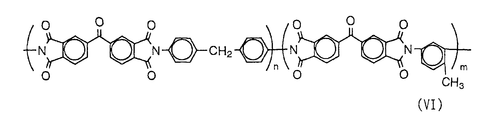
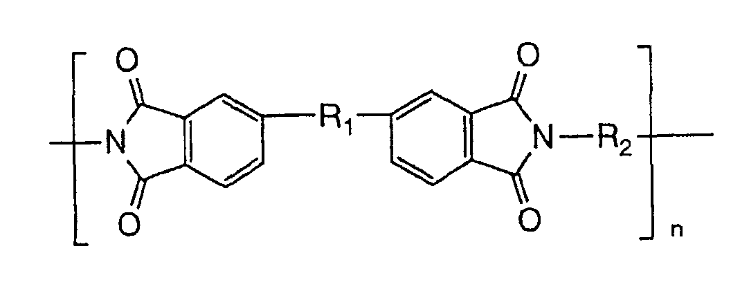
As the binder, the polyimide compound having a sufficient
mechanical strength and good carrying properties for the
infrared absorption dye has been introduced.
As described above, it is preferred that the light-heat
conversion layer is thinned to about 0.5 µm or less by selecting
the infrared absorption dye excellent in light-heat conversion
characteristics and the heat-resistant binder such as the
polyimide compound.
Technique 2 for sharpening the dot form is improvement
in characteristics of the image formation layer. When the
light-heat conversion layer is deformed, or the image formation
layer itself is deformed by intense heat, thickness unevenness
corresponding to a sub-scanning pattern of a laser beam is
developed in the image formation layer transferred to the image
receiving layer, resulting in a non-uniform image to reduce
the apparent transfer density. This tendency is significant
with a decrease in the thickness of the image formation layer.
On the other hand, when the image formation layer is thick,
the dot sharpness is impaired, and the sensitivity is lowered.
For allowing these conflicting performances to be
compatible with each other, it is preferred that a low-melting
material such as wax is added to the image formation layer,
thereby improving transfer unevenness. Further, fine
inorganic particles are added in place of the binder to properly
increase the layer thickness, which causes the image formation
layer to be sharply broken at the boundary of the heated area
and the unheated area. Thus, the transfer unevenness can be
improved while keeping the dot sharpness and sensitivity.
In general, the low-melting material such as wax tends
to ooze out on a surface of the image formation layer or to
crystallize, which poses a problem with regard to the aging
stability of image quality or the heat transfer sheet in some
cases.
For coping with this problem, the use of the low-melting
material small in the Sp value difference from the polymer of
the image formation layer is preferred. Improvement in
compatibility with the polymer can prevent separation of the
low-melting material from the image formation layer. It is
also preferred that several kinds of low-melting materials
different in structure are mixed to form a eutectic mixture,
thereby preventing crystallization. As a result, the image
having the sharp dot form and little unevenness is obtained.
The second of the characteristics of the material
techniques is that the existence of the temperature and
humidity dependency in recording sensitivity has been
discovered. In general, a moisture absorption of a coating
layer of the heat transfer sheet changes mechanical properties
and thermal properties of the layer, resulting in the
occurrence of humidity dependency of recording environment.
For decreasing this temperature and humidity dependency,
the dye/binder system of the light-heat conversion layer and
the binder system of the image formation layer are preferably
converted to organic solvent systems. Further, it is
preferred that polyvinyl butyral is selected as the binder for
the image receiving layer, and a technique for making the
polymer hydrophobic is introduced for reducing its
hydrophilicity. The techniques for making the polymer
hydrophobic include the reaction of a hydroxyl group with a
hydrophobic group and crosslinking of two or more hydroxyl
groups with a hardening agent, as described in Japanese Patent
Laid-Open No. 238858/1996.
The third of the characteristics of the material
techniques is that the hue approximation to printed matter is
improved. In addition to color matching of a pigment in a
thermal head type color proof (for example, First Proof
manufactured by Fuji Photo Film Co., Ltd.) and a stable
dispersing technique, the following problems newly
encountered in the laser heat transfer system have been solved.
That is to say, technique 1 for improving the hue approximation
to printed matter is the use of a high heat-resistant pigment.
Usually, in printing by laser exposure, heat of about 500°C
or more is also applied to the image formation layer, and some
conventional pigments are decomposed by heat. However, this
can be prevented by the adoption of the high heat-resistant
pigment in the image formation layer.
Then, technique 2 for improving the hue approximation
to printed matter is the diffusion prevention of the infrared
absorption dye. For preventing changes in hues at the time
when the infrared absorption dye moves from the light-heat
conversion layer to the image formation layer by intense heat,
it is preferred that the light-heat conversion layer is
designed as a combination of the infrared absorption dye/binder
having strong holding power as described above.
The fourth of the characteristics of the material
techniques is an increase in sensitivity. In general, energy
becomes insufficient in high-speed printing, and the spacing
corresponding to the distance of laser sub-scanning is
generated. As described above, an increase in the dye
concentration of the light-heat conversion layer and thinning
of the light-heat conversion layer and the image formation
layer can increase the efficiency of generation/transfer of
heat. Further, for achieving an effect of filling the spacing
by a slight flow of the image formation layer in heating and
improving the adhesion with the image receiving layer, the
low-melting material is preferably added to the image formation
layer. Furthermore, for improving the adhesion between the
image formation layer and the image receiving layer and giving
sufficient strength to a transferred image, it is preferred
that for example, polyvinyl butyral used in the image formation
layer is employed as a binder for the image receiving layer.
The fifth of the characteristics of the material
techniques is improvement in vacuum adhesion. The image
receiving sheet and the heat transfer sheet are preferably held
on a drum by vacuum adhesion. This vacuum adhesion is important,
because the image is formed by adhesion control of both sheets,
so that the behavior of image transfer is very sensitive to
a clearance between the image receiving layer of the image
receiving sheet and the image formation layer of the transfer
sheet. When the clearance between the materials is widened
with foreign matter such as dust as a start, an image defect
or image transfer unevenness is developed.
For preventing such an image defect or image transfer
unevenness, it is preferred that uniform unevenness is formed
on the heat transfer sheet, thereby making air passage well
to obtain a uniform clearance.
Technique 1 for improving the vacuum adhesion is
formation of unevenness on a surface of the heat transfer sheet.
The unevenness is formed on the heat transfer sheet so that
an effect of the vacuum adhesion is sufficiently achieved even
in overprinting of two or more colors. Methods for imparting
unevenness to the heat transfer sheet generally include
after-treatment such as emboss treatment and addition of a
matte agent to a coating layer. However, the addition of the
matte agent is preferred in terms of simplification of the
manufacturing process and the aging stability of the material.
The matte agent is required to have a size larger than the
thickness of a coating film, and addition of the matte agent
to the image formation layer causes the problem that an image
is broken at a portion where the matte agent exists. It is
therefore preferred that the matte gent having the optimum size
is added to the light-heat conversion layer, thereby resulting
in the approximately uniform thickness of the image formation
layer itself. Thus, an image having no defect can be obtained
on the image receiving sheet.
Then, the characteristics of systematization techniques
of the system of the invention will be described.
Characteristic 1 of the systematization techniques is
constitution of the recording device. For surely reproducing
the sharp dots as described above, high-accuracy design is
required on the recording device side. The basic constitution
is the same as with the conventional laser heat transfer
recording device. This constitution is a so-called heat mode
outer drum recording system in which recording is made by
irradiating the heat transfer sheet and the image receiving
sheet fixed on a drum with a recording head having a plurality
of high-power lasers. The following embodiments are preferred
among others.
Constitution 1 of the recording device is to avoid
contamination with dust. The image receiving sheet and the
heat transfer sheet are supplied by a full automatic roll supply
system. In the case of sheet supply in which a small number
of sheets are supplied, the sheets are contaminated by a large
amount of dust generated from the human body. Accordingly,
roll supply has been employed.
There is one roll of the heat transfer sheet for each
of four colors, so that the roll of each color is turned over
by rotation of a loading unit. Each sheet is cut to a specified
length with a cutter during loading, and then, fixed to a drum.
Constitution 2 of the recording device is to strengthen
the adhesion between the image receiving sheet and the heat
transfer sheet on a recording drum. The image receiving sheet
and the heat transfer sheet are fixed on the recording drum
by vacuum adhesion. Mechanical fixing can not strengthen the
adhesion between the image receiving sheet and the heat
transfer sheet, so that vacuum adhesion has been employed. A
large number of vacuum adhesion holes are formed on the
recording drum, and the inside of the drum is evacuated with
a blower or a pressure reducing pump, thereby adhering the
sheets by suction to the drum. The heat transfer sheet is
further adhered by suction onto the image receiving sheet
adhered by suction to the drum, so that the size of the heat
transfer sheet is designed to be larger than that of the image
receiving sheet. Air between the heat transfer sheet and the
image receiving sheet, which exerts the greatest influence on
the recording performance, is sucked from an area of only the
heat transfer sheet outside the image receiving sheet.
Constitution 3 of the recording device is to stably
accumulate the plural sheets on a discharge table. In this
device, many sheets having a large area larger than B2 can be
accumulated one over the other on the discharge table. When
a subsequent sheet B is discharged on a heat-adhesive sheet
A already accumulated, both can be adhered to each other. In
this case, the next sheet is not discharged in good order to
cause jamming. For preventing the adhesion, it is best to
prevent the sheets A and B from coming into contact with each
other. As means for preventing the contact, there are known
some methods including (a) a method of forming a difference
in level on the discharge table to make a sheet form uneven,
thereby forming a clearance between the sheets, (b) a method
of arranging a discharge outlet at a position higher than the
discharge table, and dropping a discharged sheet downward, and
(c) a method of blowing air between both sheets to float the
sheet subsequently discharged. In this system, the sheet size
is as large as B2, so that the methods of (a) and (b) require
a very large construction. Accordingly, the air blowing
method of (c) has been employed. That is to say, the method
of blowing air between both sheets to float the sheet
subsequently discharged is employed.
A structural example of this device is shown in Fig. 1.
A sequence of applying the image-forming material to this
device as described above to form a full color image
(hereinafter referred to as an image formation sequence of this
system) will be illustrated.
As the conveying roller 7 of either of a supply site or
a conveying site of the heat transfer sheet roll and the image
receiving sheet roll, there is preferably used an adhesive
roller on a surface of which an adhesive material is disposed.
The use of the adhesive roller allows cleaning of
surfaces of the heat transfer sheet and the image receiving
sheet.
The adhesive materials disposed on the surface of the
adhesive roller include an ethylene-vinyl acetate copolymer,
an ethylene-ethyl acrylate copolymer, a polyolefin resin, a
polybutadiene resin, a styrene-butadiene copolymer (SBR), a
styrene-ethylene-butene-styrene copolymer (SEBS), an
acrylonitrile-butadiene copolymer (NBR), a polyisoprene resin
(IR), a styrene-isoprene copolymer (SIS), an acrylic ester
copolymer, a polyester resin, a polyurethane resin, an acrylic
resin, butyl rubber and polynorbornene.
The adhesive roller comes into contact with the surfaces
of the heat transfer sheet and the image receiving sheet to
clean the surfaces thereof. There is no particular limitation
on the contact pressure, as long as the adhesive roller is in
contact with the surfaces thereof.
It is preferred that the adhesive material used in the
adhesive roller has a Vickers hardness Hv of 50 kg/mm2
(approximately equal to 490 MPa) or less, because dust which
is foreign matter is sufficiently removed, and an image defect
can be inhibited.
The term "Vickers hardness" means hardness measured by
applying a static load onto a pyramid diamond indenter having
an angle between the opposite faces of 136 degrees, and Vickers
hardness Hv is determined from the following equation:
Hv = 1.854 P/d2 (kg/mm2) = approximately 18.1692 P/d2
(MPa)
wherein P is weight of a load (Kg) and d is length of a diagonal
line of a square of a hollow.
Further, in the invention, it is preferred that the
adhesive material used in the adhesive roller has an elastic
coefficient at 20°C of 200 kg/mm2 (approximately equal to 19.6
MPa) or less, because dust which is foreign matter is
sufficiently removed, and an image defect can be inhibited,
similarly to the above.
Characteristic 2 of the systematization techniques is
constitution of the heat transfer device.
For transferring the image sheet on which the image is
printed with the recording device to an actual printing paper
(referred to as "final paper" or "final print paper" ), the
heat transfer device is used. This process is entirely
identical to that of First ProofTD. When the image receiving
sheet is overlaid with the final paper and heat and pressure
are applied thereto, both are adhered to each other. Then,
when the image receiving sheet is peeled off from the final
paper, only the image and the adhesive layer remain on the final
paper, and a support of the image receiving sheet and a cushion
layer are separated. Accordingly, the image is practically
transferred from the image receiving sheet to the final paper.
In First ProofTD, an aluminum guide plate is overlaid with
final paper and an image receiving sheet, and passed between
heat rollers to transfer an image. The aluminum guide plate
is used for preventing deformation of the final paper. However,
when this is employed in the system used in the invention, an
aluminum guide plate larger in size than B2 becomes necessary,
which poses the problem that the installation space of the
devise is increased. Then, in this system, such a structure
that no aluminum guide is used and further a conveying pass
is turned at an angle of 180 degrees to discharge the final
paper and the image receiving sheet to the insertion side is
employed. Accordingly, the installation space of the devise
has become very compact (Fig. 2). However, the use of no
aluminum guide causes the problem that the final paper is
deformed. Specifically, a pair of the final paper and the image
receiving sheet discharged are curled with the image receiving
sheet facing inside, resulting in rolling on the discharge
table. It is very difficult as an operation to peel off the
image receiving sheet from the rolled-up final paper.
Then, for preventing the rolling-up, there are
considered a bimetal effect caused by the difference in
shrinkage between the final paper and the image receiving sheet
and an ironing effect due to a structure of winding around a
heat roller. When the image receiving sheet is laid on the
final paper and inserted as in a conventional method, the heat
shrinkage of the image receiving sheet in the direction of
insertion and movement is greater than that of the final paper,
so that the upper sheet is disposed inside a curl caused by
the bimetal effect. This curl direction agrees with the
direction of a curl due to the ironing effect, so that the curl
becomes increasingly strong by the synergistic effect.
However, when the image receiving sheet and the final paper
are inserted so that the image receiving sheet is placed under
the final paper, the curl caused by the bimetal effect faces
downward, and the curl due to the ironing effect faces upward.
Accordingly, the problem of the curl has been solved by
cancellation.
A sequence of final paper transfer (hereinafter referred
to as a final paper transfer method used in this system) is
as follows. A
heat transfer device 41 used in this method,
which is shown in Fig. 2, is a manually operated device,
different from the recording device.
Characteristic 3 of the systematization techniques is
constitution of a system.
The function as a color proof can be exhibited by
connecting the device described above to a plate making system.
As the system, printed matter having image quality extremely
close to that of printed matter supplied from certain plate
making data is required to be supplied from the proof. Then,
a software for bringing color and halftone dots close to the
printed matter is necessary. A specific connecting example
will be introduced.
When a proof of printed matter from a plate making system,
Celebra™ manufactured by Fuji Photo Film Co., Ltd., is taken,
system connection is as follows. A CTP (computer to plate)
system is connected to Celebra. A printing plate supplied
therefrom is subjected to a printing machine, thereby obtaining
final printed matter. As the color proof, Luxel FINALPROOF
5600 (hereinafter also referred to as FINALPROOF) manufactured
by Fuji Photo Film Co., Ltd., which is the above-mentioned
recording device, is connected to Celebra. During that, PD
systemTD manufactured by Fuji Photo Film Co., Ltd. is connected
as a proof drive software for bringing color and halftone dots
close to the printed matter.
Contone (continuous tone) data converted to luster data
by Celebra are converted to binary data for halftone dots,
supplied to the CTP system, and finally printed. On the other
hand, the same contone data are also supplied to the PD system.
The PD system converts the received data by a four-dimensional
(black, cyan, magenta and yellow) table so that color agrees
with the above-mentioned printed matter. Finally, the data
are converted to binary data for halftone dots so that they
agree with halftone dots of the above-mentioned printed matter,
and supplied to FINALPROOF (Fig. 3).
The four-dimensional table is previously experimentally
prepared, and stored in the system. An experiment for
preparing the table is as follows. An image in which important
color data are printed through the CTP system and an image in
which the data are supplied to FINALPROOF through the PD system
are prepared, and colorimetric values thereof are compared with
each other. Then, the table is prepared so that the difference
between them is minimized.
As described above, according to the invention, system
constitution can be realized which can fully exhibit the
ability of the high-resolution material.
The heat transfer sheet, a material used in the system
of the invention, will be described below.
It is preferred that the absolute value of the difference
between the surface roughness Rz of a surface of the image
formation layer of the heat transfer sheet and the surface
roughness Rz of a surface of a back layer thereof is 3.0 µm
or less, and that the absolute value of the difference between
the surface roughness Rz of a surface of the image receiving
layer of the image receiving sheet and the surface roughness
Rz of a surface of a back layer thereof is 3.0µm or less. Such
constitution, coupled with the above-mentioned cleaning means,
can prevent an image defect, prevent a conveying jam, and
further improve dot gain stability.
In this specification, the term "surface roughness Rz"
means an average surface roughness from ten measurements
corresponding to Rz (maximum height) of JIS, and a value
obtained by inputting and converting a distance between the
average value of the heights of the highest to the fifth
mountains and the average value of the depths of the deepest
to the fifth valleys, taking as a reference plane an average
plane of portions sampled from a curved surface of roughness
by a reference area. A contact finger type three-dimensional
roughness tester (Surfcom 570A-3DF) manufactured by Tokyo
Seimitsu Co. Ltd. is used for measurement. The measuring
direction is a longitudinal direction, the cutoff value is 0.08
mm, the measuring area is 0.6 mm X 0.4 mm, the feed pitch is
0.005 mm, and the measuring speed is 0.12 mm/s.
From the viewpoint of more improving the above-mentioned
effect, it is preferred that the absolute value of the
difference between the surface roughness Rz of the surface of
the image formation layer of the heat transfer sheet and the
surface roughness Rz of the surface of the back layer thereof
is 1.0 µm or less, and that the absolute value of the difference
between the surface roughness Rz of the surface of the image
receiving layer of the image receiving sheet and the surface
roughness Rz of the surface of the back layer thereof is 1.0
µm or less.
Further, as another embodiment, it is preferred that the
surface roughness Rz of the surface of the image formation layer
of the heat transfer sheet and the surface of the back layer
thereof, and/or the surface of the image receiving layer of
the image receiving sheet and the surface of the back layer
thereof is from 2 µm to 30 µm. Such constitution, coupled with
the above-mentioned cleaning means, can prevent an image defect,
prevent a conveying jam, and further improve dot gain
stability.
The glossiness of the image formation layer of the heat
transfer sheet is also preferably from 80 to 99.
The glossiness greatly depends on the smoothness of the
surface of the image formation layer, and can exert an influence
on the uniformity of the thickness of the image formation layer.
The higher glossiness results in the uniform image formation
layer, which is more suitable for the application to highly
fine images. However, the higher glossiness results in more
increased resistance in conveying, and both are in the
trade-off relationship. When the glossiness is within the
range of 80 to 99, both are compatible and balanced.
Then, the outline of a mechanism of multicolor image
formation by thin film heat transfer using a laser beam will
be described with reference to Fig. 4.
An image receiving sheet 20 is laminated on a surface
of an image formation layer 16 of a heat transfer sheet 10,
the layer 16 containing a black (K), cyan (C), magenta (M) or
yellow (Y) pigment, thereby preparing a laminate 30 for image
formation. The heat transfer sheet 10 comprises a support 12
having provided thereon a light-heat conversion layer 14 and
an image formation layer 16 in this order. The image receiving
layer 20 comprises a support 22 having provided thereon an image
receiving layer 24. The image receiving sheet 20 is laminated
with the heat transfer sheet 10 in such a manner that the image
receiving layer 24 comes in contact with the image formation
layer 16 of the heat transfer sheet 10 (Fig. 4(a)). When the
laminate 30 is irradiated imagewise with a laser beam
time-sequentially from the side of the support 12 of the heat
transfer sheet 10, a laser beam-irradiated region of the
light-heat conversion layer 14 of the heat transfer sheet 10
develops heat to reduce adhesion with the image formation layer
16 (Fig. 4(b)). Then, the heat transfer sheet 10 is separated
from the image receiving sheet 20, and at this time, a laser
beam-irradiated region 16' of the image formation layer 16 is
transferred onto the image receiving layer 24 of the image
receiving sheet 20 (Fig. 4(c)).
In the multicolor image formation, multiple laser beams
are preferably used for light irradiation, and a multiple-beam
two-dimensional arrangement is particularly preferred. The
term "multiple-beam two-dimensional arrangement" means that
plural laser beams are used in recording by laser irradiation,
and that a spot arrangement of these laser beams is a
two-dimensional plane arrangement comprising plural columns
along a main scanning direction and plural rows along a
sub-scanning direction.
The use of laser beams of the multiple-beam
two-dimensional arrangement can decrease the time required for
laser recording.
There is no particular limitation on the laser beam used.
the available laser beams include gas laser beams such as argon
ion laser beams, helium neon laser beams and helium cadmium
laser beams, solid laser beams such as YAG laser beams, direct
laser beams such as semiconductor laser beams, dye laser beams
and excimer laser beams. Laser beams in which the wavelength
is converted to half by passing these laser beams through a
secondary harmonic element can also be used. In the multicolor
image formation method, the use of semiconductor laser beams
is preferred, considering output power and the ease of
modulation. In the multicolor image formation method, the
laser beams are preferably irradiated under such conditions
that the beam diameter on the light-heat conversion layer is
within the range of 5 µm to 50 µm (particularly 6 µm to 30 µm),
and the scanning speed is preferably 1 m/second or more
(particularly 3 m/second or more).
Further, in the multicolor image formation, the
thickness of the image formation layer in the heat transfer
sheet of black is preferably thicker than that of each heat
transfer sheet of yellow, magenta and cyan, and from 0.5 µm
to 0.7 µm. This can inhibit a decrease in density caused by
transfer unevenness when the heat transfer sheet of black is
subjected to laser irradiation.
When the thickness of the image formation layer in the
heat transfer sheet of black is adjusted to 0.5 µm or more,
no transfer unevenness is developed and image density is
maintained in recording at high energy. Thus, image density
necessary for a print proof can be achieved. This tendency
becomes more significant under conditions of high humidity,
so that changes in density according to the environment can
be inhibited. On the other hand, transfer sensitivity in laser
recording can be maintained, and small points and thin lines
are also improved, by adjusting the above-mentioned thickness
to 0.7 µm or less. This tendency is more significant under
conditions of low humidity. Further, resolving power can also
be improved. The thickness of the image formation layer in
the heat transfer sheet of black is more preferably from 0.55
µm to 0.65 µm, and particularly preferably 0.60 µm.
Further, it is preferred that the thickness of the image
formation layer in the heat transfer sheet of black is 0.5 µm
to 0.7 µm, and that the thickness of the image formation layer
in each heat transfer sheet of yellow, magenta and cyan is from
0.2 µm to less than 0.5 µm.
When the thickness of the image formation layer in each
heat transfer sheet of yellow, magenta and cyan is adjusted
to 0.2 µm or more, no transfer unevenness is developed and image
density is maintained in recording. On the other hand, when
the thickness is adjusted to 0.5 µm or less, transfer
sensitivity and resolving power can be improved. More
preferably, the thickness is from 0.3 µm to 0.45 µm.
It is preferred that the image formation layer in the
heat transfer sheet of black contains carbon black. The carbon
black preferably comprises at least two kinds of carbon blacks
different in coloring power, because reflection density can
be controlled while keeping the P/B (pigment/binder) ratio
within the constant range.
The coloring power of carbon black is represented by
various methods, which include, for example, PVC blackness
described in Japanese Patent Laid-Open No. 140033/1998. The
PVC blackness is evaluated by adding carbon black to a PVC resin,
dispersing it with a twin-roll mill, forming the resulting
product into a sheet, and visually judging the blackness of
a sample, compared with the blackness of each of carbon blacks
"#40" and "#45" manufactured by Mitsubishi Chemical
Corporation, which is graded into 1 to 10 and a reference value.
Two or more kinds of carbon blacks different in PVC blackness
can be appropriately selected for use depending on the purpose.
A specific method for preparing a sample will be
described below.
<Method for Preparing Sample>
In a 250-cc Banbury mixer, 40% by weight of sample carbon
black is mixed with a LDPE (low-density polyethylene) resin,
followed by kneading at 115°C for 4 minutes.
| Compounding Conditions |
| LDPE Resin | 101.89 g |
| Calcium Stearate | 1.39 g |
| Irganox 1010 | 0.87 g |
| Sample Carbon Black | 69.43 g |
Then, the kneaded product is diluted to a carbon black
concentration of 1% by weight at 120°C by use of a twin-roll
mill.
| Conditions for Preparing Diluted Compound |
| LDPE Resin | 58.3 g |
| Calcium Stearate | 0.2 g |
| Resin Containing 40% by Weight Carbon Black | 1.5 g |
The compound is formed into a sheet at a slit width of
0.3 mm, and the resulting sheet is cut to chips. Then, the
chips are formed into a film having a thickness of 65 ± 3 µm
on a hot plate of 240°C.
As a method for forming the multicolor image, many image
layers (image formation layers on which images are formed) may
be repeatedly overlaid on the same image receiving sheet, using
the heat transfer sheet as described above, thereby forming
the multicolor image, or images may be once formed on the image
receiving layers of the plural image receiving sheets and then
transferred again to final print paper, thereby forming the
multicolor image.
As to the latter, for example, the heat transfer sheets
having the image formation layers containing colorants
different from each other in hues are prepared, and combined
with the image receiving sheets to independently produce four
kinds (four colors, cyan, magenta, yellow and black) of
laminates for image formation. Each laminate is subjected to
laser irradiation according to a digital signal based on the
image, for example, through a color separation filter, and
subsequently, each heat transfer sheet is separated from each
image receiving sheet to independently form a color separation
image of each color on the image receiving sheet. Then, each
color separation image formed can be in turn laminated on an
actual support such as final print paper separately prepared
or a support similar thereto, thereby forming the multicolor
image.
In the heat transfer recording using laser beam
irradiation, it is preferred that the image is formed on the
image receiving sheet by the thin film transfer system in which
the laser beam is converted to heat, and the pigment-containing
image formation layer is transferred to the image receiving
sheet by utilizing the heat energy thus generated. However,
the technique used for the development of the image-forming
material comprising the heat transfer sheet and the image
receiving sheet is appropriately applicable to the development
of heat transfer sheets and/or image receiving sheets used in
the melt transfer system, ablation transfer system and the
sublimation transfer system, and the system of the invention
also includes image-forming materials used in these systems.
The heat transfer sheet and the image receiving sheet
will be described in details below.
[Heat Transfer Sheet]
The heat transfer sheet comprises the support having
provided thereon the light-heat conversion layer and the image
formation layer, and further another layer as needed.
(Support)
There is no particular limitation on the material for
the support of the heat transfer sheet. Various support
materials can be used depending on the purpose. The support
materials are preferably ones having rigidity, good in
dimensional stability and resistant to heat in image formation.
Preferred examples of the support materials include synthetic
resin materials such as polyethylene terephthalate,
polyethylene 2,6-naphthalate, a polycarbonate, polymethyl
methacrylate, polyethylene, polypropylene, polyvinyl
chloride, polyvinylidene chloride, polystyrene, a
styrene-acrylonitrile copolymer, a polyamide (aromatic or
aliphatic), a polyimide, a polyamideimide and a polysulfone.
Above all, a biaxially stretched polyethylene terephthalate
film is preferred, considering mechanical strength and
dimensional stability to heat. When used for the preparation
of the color proof utilizing laser recording, the support for
the heat transfer sheet is preferably formed from a transparent
synthetic resin material transmitting the laser beam. The
thickness of the support is preferably from 25 µm to 130 µm,
and particularly preferably from 50 µm to 120 µm. The center
line average height Ra of the support on the image formation
layer side (measured based on JIS B0601 using a surface
roughness tester (Surfcom manufactured by Tokyo Seimitsu Co.
Ltd.) is preferably less than 0.1 µm. Longitudinal Young's
modulus of the support is preferably from 200 kg/mm2 to 1200
kg/mm2 (approximately equal to 2 GPa to 12 GPa), and lateral
Young's modulus thereof is preferably from 250 kg/mm2 to 1600
kg/mm2 (approximately equal to 2.5 GPa to 16 GPa). The
longitudinal F-5 value of the support is preferably from 5
kg/mm2 to 50 kg/mm2 (approximately equal to 49 MPa to 490 MPa),
and the lateral F-5 value of the support is preferably from
3 kg/mm2 to 30 kg/mm2 (approximately equal to 29.4 MPa to 294
MPa). The longitudinal F-5 value of the support is generally
higher than the lateral F-5 value of the support. However,
when it is particularly necessary to increase the lateral
strength, this does not apply to the case. The degrees of heat
shrinkage of the support in longitudinal and lateral directions
at 100°C for 30 minutes are preferably 3% or less, and more
preferably 1.5% or less, and those at 80°C for 30 minutes are
preferably 1% or less, and more preferably 0.5% or less. The
breaking strengths are preferably from 5 kg/mm2 to 100 kg/mm2
(approximately equal to 49 MPa to 980 MPa) in both directions,
and the elasticities are preferably from 100 kg/mm2 to 2000
kg/mm2 (approximately equal to 0.98 GPa to 19.6 GPa).
For improving the adhesion between the support of the
heat transfer sheet and the light-heat conversion layer
provided thereon, the support may be subjected to surface
activation treatment and/or provided with one or more undercoat
layers. The surface activation treatment includes, for
example, glow discharge treatment and corona discharge
treatment. A material for the undercoat layer is preferably
high in adhesion to both surfaces of the support and the
light-heat conversion layer, low in heat conductivity and
excellent in heat resistance. Examples of such materials
include styrene, a styrene-butadiene copolymer and gelatin.
The thickness of the whole undercoat layer is usually 0.01 µm
to 2 µm. Further, a surface on the side opposite to the
light-heat conversion layer side of the heat transfer sheet
can also be provided with various functional layers such as
an antireflection layer and an antistatic layer, or surface
treated, as needed.
(Back Layer)
A back layer is preferably provided on the surface on
the side opposite to the light-heat conversion layer side of
the heat transfer sheet. It is preferred that the support has
a first back layer adjacent to the support and a second back
layer provided on the side opposite to the first back layer
side. In the invention, the ratio of a weight A of an antistatic
agent contained in the first back layer to a weight B of that
contained in the second back layer (B/A) is preferably less
than 0.3. When the B/A ratio is 0.3 or more, lubricity and
powdering from the back layer tend to deteriorate.
The thickness C of the first back layer is preferably
0.01 µm to 1 µm, and more preferably from 0.01 µm to 0.2 µm.
The thickness D of the second back layer is preferably 0.01
µm to 1 µm, and more preferably from 0.01 µm to 0.2 µm. The
ratio of the thickness of the first back layer to the thickness
of the second back layer (C:D) is preferably from 1:2 to 5:1.
The antistatic agents used in the first and second back
layers include nonionic surfactants such as polyoxyethylenealkylamines
and glycerol esters of fatty acids, cationic
surfactants such as quaternary ammonium salts, and anionic
surfactants such as alkyl phosphates, amphoteric surfactants
and compounds such as conductive resins.
Fine conductive particles can also be used as the
antistatic agent. Such conductive particles include, for
example, Oxides such as ZnO, TiO2, SnO2, Al2O3, In2O3, MgO, BaO,
CoO, CuO, Cu2O, CaO, SrO, BaO2, PbO, PbO2, MnO3, MoO3, SiO2, ZrO2,
Ag2O, Y2O3, Bi2O3, Ti2O3, Sb2O3, Sb2O5, K2Ti6O13, NaCaP2O18 and
MgB2O5; sulfides such as Cus and ZnS; carbides such as SiC, TiC,
ZrC, VC, NbC, MoC and WC; nitrides such as Si3N4, TiN, ZrN, VN,
NbN and Cr2N; borides such as TiB2, ZrB2, NbB2, TaB2, CrB, MoB,
WB and LaB5; silicides such as TiSi2, ZrSi2, NbSi2, TaSi2, CrSi2,
MoSi2 and WSi2; metal salts such as BaCO3, CaCO3, SrCO3, BaSO4
and CaSO4; and complexes such as SiN4-SiC and 9Al2O3-2B2O3. They
may be used either alone or as a combination of two or more
of them. Of these, SnO2, ZnO, Al2O3, TiO2, In2O3, MgO, BaO and
MoO3 are preferred, SnO2, ZnO, In2O3 and TiO2 are more preferred,
and SnO2 is particularly preferred.
When the heat transfer material of the invention is used
in the laser heat transfer recording system, it is preferred
that the antistatic agent used in the back layer is transparent
so that the laser beam can be transmitted.
When the conductive metal oxide is used as the antistatic
agent, it is preferred that the particle size thereof is smaller,
for minimizing light scattering. This is to be determined
using the ratio of the refractive index of the particles to
that of a binder as a parameter, and can be determined by using
the theory of Mie. In general, the average particle size is
within the range of 0.001 µm to 0.5 µm, and preferably within
the range of 0.003 µm to 0.2 µm. The term "average particle
size" as used herein means a value including not only a primary
particle size of the conductive metal oxide, but also a particle
size of a higher-order structure.
In addition to the antistatic agent, various additives
such as a surfactant, a lubricant and a matte agent and a binder
can be added to the first and second back layers. The amount
of the antistatic agent contained in the first back layer is
preferably from 10 parts to 1000 parts by weight, and more
preferably from 200 parts to 800 parts by weight, based on 100
parts by weight of binder. Further, the amount of the
antistatic agent contained in the second back layer is
preferably from 0 parts to 300 parts by weight, and more
preferably from 0 parts to 100 parts by weight, based on 100
parts by weight of binder.
The binders used for formation of the first and second
back layers include homopolymers and copolymers of acrylic acid
monomers such as acrylic acid, methacrylic acid, acrylates and
methacrylates, cellulose esters such as nitrocellulose,
methyl cellulose, ethyl cellulose and cellulose acetate, vinyl
polymers and copolymers of vinyl compounds such as polyethylene,
polypropylene, polystyrene, vinyl chloride copolymers, vinyl
chloride-vinyl acetate copolymers, polyvinylpyrrolidone,
polyvinyl butyral and polyvinyl alcohol, condensation
polymers such as polyesters, polyurethanes and polyamides,
rubber thermoplastic polymers such as butadiene-styrene
copolymers, polymers obtained by polymerization or
crosslinking of photopolymerizable or thermopolymerizable
compounds such as epoxy compounds, and melamine compounds.
(Light-Heat Conversion Layer)
The light-heat conversion layer contains a light-heat
conversion material and a binder, a matte agent as needed, and
further another component as needed.
The light-heat conversion material is a material having
the function of converting irradiated light energy to heat
energy. In general, it is a dye (including a pigment,
hereinafter the same) which can absorb a laser beam. When an
image is recorded with an infrared laser, an infrared
absorption dye is preferably used as the light-heat conversion
material. Examples of the dyes include black pigments such
as carbon black, pigments of macrocyclic compounds having
absorption in a region from the visible to the near infrared
region such as phthalocyanine and naphthalocyanine, organic
dyes used as laser absorption materials for high-density laser
recording on optical disks (cyanine dyes such as indolenine
dyes, anthraquinone dyes, azulene dyes and phthalocyanine
dyes), and organic metal compound dyes such as thiol nickel
complexes. Above all, the cyanine dyes are preferred, because
they show high absorbance index to light in the infrared region,
so that the use thereof as the light-heat conversion materials
can thin the light-heat conversion layer, resulting in more
improvement in the recording sensitivity of the heat transfer
sheet.
As the light-heat conversion materials, there can also
be used inorganic materials including granular metal materials
such as blackened silver.
The binder contained in the light-heat conversion layer
is preferably a resin having at least strength enough to form
a layer on the support, and high heat conductivity. Further,
a heat-resistant resin which is not decomposed even by heat
generated from the light-heat conversion material in image
recording is preferred, because the smoothness of the surface
of the light-heat conversion layer after light irradiation can
be maintained even when high-energy light irradiation is
carried out. Specifically, a resin having a thermal
decomposition temperature (a temperature at which the weight
is decreased by 5% in a stream of air at a rate of temperature
rise of 10°C/minute by the TGA method (thermal mass
spectrometric analysis)) of 400°C or more is preferred, and
a resin having a thermal decomposition temperature of 500°C
or more is more preferred.
It is preferred that the binder has a glass transition
temperature of 200°C to 400°C, and it is more preferred that
the binder has a glass transition temperature of 250°C to 350°C.
A glass transition temperature of lower than 200°C results in
development of fogging on an image formed in some cases, whereas
exceeding 400°C results in deterioration of solubility of the
resin, which causes production efficiency to decrease in some
cases.
It is preferred that the binder used in the light-heat
conversion layer is higher in heat resistance (for example,
thermal deformation temperature and thermal decomposition
temperature) than the materials used in the other layers
provided on the light-heat conversion layer.
Specific examples thereof include acrylic acid resins
such as polymethyl methacrylate, a polycarbonate, vinyl resins
such as polystyrene, a vinyl chloride/vinyl acetate copolymer
and polyvinyl alcohol, polyvinyl butyral, polyesters,
polyvinyl chloride, polyamides, polyimides, polyetherimides,
polysulfones, polyethersulfones, alamid, polyurethanes,
epoxy resins and urea/melamine resins. Of these, polyimide
resins are preferred.
In particular, polyimide resins represented by the
following general formulas (I) to (VII) are soluble in organic
solvents, and the use of these polyimide resins is preferred
because of improvement in productivity of the heat transfer
sheet. Further, the use thereof is preferred also in terms
of improvements in viscosity stability, long-term keeping
quality and moisture resistance of a coating solution for the
light-heat conversion layer.
In general formulas (I) and (II), Ar
1 represents an
aromatic group represented by any one of the following
structural formulas (1) to (3), and n represents an integer
of from 10 to 100.
In general formulas (III) and (IV), Ar
2 represents
an aromatic group represented by any one of the following
structural formulas (4) to (7), and n represents an integer
of from 10 to 100.
In general formulas (V) to (VII), n and m each represents
an integer of from 10 to 100. In general formula (VI), the
n:m ratio is from 6:4 to 9:1.
As a measure for judging whether the resin is soluble
in the organic solvent or not, the basis that 10 parts by weight
or more of the resin is dissolved in 100 parts by weight of
N-methylpyrrolidone at 25°C is used. When the resin is
dissolved in an amount of 10 parts by weight or more, it is
preferably used as the resin for the light-heat conversion
layer. When the resin is dissolved in an amount of 100 parts
by weight or more based on 100 parts by weight of
N-methylpyrrolidone, that resin is more preferably used.
The matte agents contained in the light-heat conversion
layer include fine inorganic particles and fine organic
particles. The fine inorganic particles include metal salts
such as silica, titanium oxide, aluminum oxide, zinc oxide,
magnesium oxide, barium sulfate, magnesium sulfate, aluminum
hydroxide, magnesium hydroxide and boron nitride, kaolin, clay,
talc, zinc white, white lead, zeaklite, quartz, diatomaceous
earth, pearlite, bentonite, mica and synthetic mica. The fine
organic particles include resin particles such as fluororesin
particles, guanamine resin particles, acrylic resin particles,
styrene-acrylic copolymer resin particles, silicone resin
particles, melamine resin particles and epoxy resin particles.
The particle size of the matte agent is usually from 0.3
µm to 30 µm, and preferably from 0.5 µm to 20 µm. The amount
thereof added is preferably from 0.1 mg/m2 to 100 mg/m2.
The light-heat conversion layer may further contain a
surfactant, a thickening agent and an antistatic agent as
needed.
The light-heat conversion layer can be formed by
dissolving the light-heat conversion material and the binder,
adding thereto the matte agent and other components as needed
to prepare a coating solution, applying the solution onto the
support, and drying it. Organic solvents for dissolving the
polyimide resins include, for example, n-hexane, cyclohexane,
diglime, xylene, toluene, ethyl acetate, tetrahydrofuran,
methyl ethyl ketone, acetone, cyclohexanone, 1,4-dioxane,
1,3-dioxane, dimethyl acetate, N-methyl-2-pyrrolidone,
dimethyl sulfoxide, dimethylformamide, dimethylacetoamide,
γ-butyrolactone, ethanol and methanol. Coating and drying can
be conducted by conventional methods. Drying is conducted
usually at a temperature of 300°C or lower, and preferably at
a temperature of 200°C or lower. When polyethylene
terephthalate is used as the support, drying is preferably
conducted at a temperature of 80°C to 150°C.
When the amount of the binder contained in the light-heat
conversion layer is too small, the cohesive force of the
light-heat conversion layer is decreased, and when the formed
image is transferred to the image receiving sheet, the
light-heat conversion layer becomes liable to be transferred
together, which causes color mixture. Further, when the
amount of the polyimide is too large, the thickness of the
light-heat conversion layer for achieving a definite light
absorption rate is increased to be liable to cause a reduction
in sensitivity. The solid weight ratio of the light-heat
conversion material to the binder in the light-heat conversion
layer is preferably from 1:20 to 2:1, and more preferably from
1:10 to 2:1.
When the light-heat conversion layer is thinned, the
sensitivity of the heat transfer sheet is preferably enhanced.
The thickness of the light-heat conversion layer is preferably
from 0.03 µm to 1.0 µm, and more preferably from 0.05 µm to
0.5 µm. It is preferred that the light-heat conversion layer
has an optical density of 0.90 to 1.41 to a peak wavelength
of a laser beam, for example, a wavelength of 808 nm, because
the transfer sensitivity of the image formation layer is
improved. It is more preferred that the light-heat conversion
layer has an optical density of 1.03 to 1.29 to the
above-mentioned wavelength. When the optical density at the
peak wavelength of the laser beam is less than 0.90, conversion
of irradiated light to heat becomes insufficient, sometimes
resulting in a reduction in transfer sensitivity. On the other
hand, when it exceeds 1.41, the function of the light-heat
conversion layer is influenced in recording to cause fogging
in some cases.
In the invention, the optical density of the light-heat
conversion layer of the heat transfer sheet means the
absorbance of the light-heat conversion layer at a peak
wavelength of a laser beam used in recording the image-forming
material, and can be measured with a known spectrophotometer.
In the invention, there is used an UV spectrophotometer, UV-240,
manufactured by Shimadzu Corp. The above-mentioned optical
density is a value obtained by subtracting a value of the
support alone from a value including the support.
(Image Formation Layer)
The image formation layer contains at least a pigment
transferred to the image receiving sheet to form an image and
further a binder for forming the layer, and another component
as needed.
The pigments can be generally classified roughly into
organic pigments and inorganic pigments. The former are
particularly excellent in transparency of a coating film, and
the later are generally excellent in opacifying properties.
Accordingly, they may be appropriately selected depending on
the purpose. When the above-mentioned heat transfer sheet is
used for a print color proof, organic pigments agree with or
close in hues to yellow, magenta, cyan and black generally used
in print ink are suitably used. Besides, metal powders and
fluorescent pigments are also used in some cases. Examples
of the pigments suitably used include azo pigments,
phthalocyanine pigments, anthraquinone pigments, dioxazine
pigments, quinacridone pigments, isoindolinone pigments and
nitro pigments. The pigments used for the image formation
layer are enumerated below, classified by hue, but are not
limited thereto.
1) Yellow Pigments
Pigment Yellow 12 (C.I. No. 21090)
Examples: Permanent Yellow DHG (manufactured by Clariant
Japan K.K.), Lionol Yellow 1212B (manufactured by Toyo Ink Mfg.
Co. Ltd.), Irgalite Yellow LCT (manufactured by Ciba Specialty
Chemicals K.K.) and Symuler Fast Yellow GTF 219 (manufactured
by Dainippon Ink & Chemicals Inc.)
Pigment Yellow 13 (C.I. No. 21100)
Examples: Permanent Yellow GR (manufactured by Clariant
Japan K.K.) and Lionol Yellow 1313 (manufactured by Toyo Ink
Mfg. Co. Ltd.)
Pigment Yellow 14 (C.I. No. 21095)
Examples: Permanent Yellow G (manufactured by Clariant
Japan K.K.), Lionol Yellow 1401-G (manufactured by Toyo Ink
Mfg. Co. Ltd.), Seika Fast Yellow 2270 (manufactured by
Dainichiseika Colour & Chemicals Mfg. Co., Ltd.) and Symuler
Fast Yellow GTF 4400 (manufactured by Dainippon Ink & Chemicals
Inc.)
Pigment Yellow 17 (C.I. No. 21105)
Examples: Permanent Yellow GG02 (manufactured by
Clariant Japan K.K.) and Symuler Fast Yellow 8GF (manufactured
by Dainippon Ink & Chemicals Inc.)
Pigment Yellow 155
Examples: Graphtol Yellow 3GP (manufactured by Clariant
Japan K.K.)
Pigment Yellow 180 (C.I. No. 21290)
Examples: Novoperm Yellow P-HG (manufactured by Clariant
Japan K.K.) and PV Fast Yellow HG (manufactured by Clariant
Japan K.K.)
Pigment Yellow 139 (C.I. No. 56298)
Examples: Novoperm Yellow M2R 70 (manufactured by
Clariant Japan K.K.)
2) Magenta Pigments
Pigment Red 57:1 (C.I. No. 15850:1)
Examples: Graphtol Rubine L6B (manufactured by Clariant
Japan K.K.), Lionol Red 6B-4290G (manufactured by Toyo Ink Mfg.
Co. Ltd.), Irgalite Rubine 4BL (manufactured by Ciba Specialty
Chemicals K.K.) and Symuler Brilliant Carmine 6B-229
(manufactured by Dainippon Ink & Chemicals Inc.)
Pigment Red 122 (C.I. No. 73915)
Examples: Hosterperm Pink E (manufactured by Clariant
Japan K.K.), Lionogen Magenta 5790 (manufactured by Toyo Ink
Mfg. Co. Ltd.) and Fastogen Super Magenta RH (manufactured by
Dainippon Ink & Chemicals Inc.)
Pigment Red 53:1 (C.I. No. 15585:1)
Examples: Permanent Lake Red LCY (manufactured by
Clariant Japan K.K.) and Symuler Lake Red C conc (manufactured
by Dainippon Ink & Chemicals Inc.)
Pigment Red 48:1 (C.I. No. 15865:1)
Examples: Lionogen Red 2B 3300 (manufactured by Toyo Ink
Mfg. Co. Ltd.) and Symuler Red NRY (manufactured by Dainippon
Ink & Chemicals Inc.)
Pigment Red 48:2 (C.I. No. 15865:2)
Examples: Permanent Red W2T (manufactured by Clariant
Japan K.K.), Lionol Red LX235 (manufactured by Toyo Ink Mfg.
Co. Ltd.) and Symuler Red 3012 (manufactured by Dainippon Ink
& Chemicals Inc.)
Pigment Red 48:3 (C.I. No. 15865:3)
Examples: Permanent Red 3RL (manufactured by Clariant
Japan K.K.) and Symuler Red 2BS (manufactured by Dainippon Ink
& Chemicals Inc.)
Pigment Red 177 (C.I. No. 65300)
Examples: Cromophtal Red A2B (manufactured by Ciba
Specialty Chemicals K.K.)
3) Cyan Pigments
Pigment Blue 15 (C.I. No. 74160)
Examples: Lionol Blue 7027 (manufactured by Toyo Ink Mfg.
Co. Ltd.) and Fastogen Blue BB (manufactured by Dainippon Ink
& Chemicals Inc.)
Pigment Blue 15:1 (C.I. No. 74160)
Examples: Hosterperm Blue A2R (manufactured by Clariant
Japan K.K.) and Fastogen Blue 5050 (manufactured by Dainippon
Ink & Chemicals Inc.)
Pigment Blue 15:2 (C.I. No. 74160)
Examples: Hosterperm Blue AFL (manufactured by Clariant
Japan K.K.), Irgalite Blue BSP (manufactured by Ciba Specialty
Chemicals K.K.) and Fastogen Blue GP (manufactured by Dainippon
Ink & Chemicals Inc.)
Pigment Blue 15:3 (C.I. No. 74160)
Examples: Hosterperm Blue B2G (manufactured by Clariant
Japan K.K.), Lionol Blue FG7330 (manufactured by Toyo Ink Mfg.
Co.Ltd.), Cromophtal Blue 4GNP (manufactured by Ciba Specialty
Chemicals K.K.) and Fastogen Blue FGF (manufactured by
Dainippon Ink & Chemicals Inc.)
Pigment Blue 15:4 (C.I. No. 74160)
Examples: Hosterperm Blue BFL (manufactured by Clariant
Japan K.K.), Cyanine Blue 700-10FG (manufactured by Toyo Ink
Mfg. Co. Ltd.), Irgalite Blue GLNF (manufactured by Ciba
Specialty Chemicals K.K.) and Fastogen Blue FGS (manufactured
by Dainippon Ink & Chemicals Inc.)
Pigment Blue 15:6 (C.I. No. 74160)
Examples: Lionol Blue ES (manufactured by Toyo Ink Mfg.
Co. Ltd.)
Pigment Blue 60 (C.I. No. 69800)
Examples: Hosterperm Blue RL01 (manufactured by Clariant
Japan K.K.) and Lionogen Blue 6501 (manufactured by Toyo Ink
Mfg. Co. Ltd.)
4) Black Pigments
Pigment Black 7 (Carbon Black C.I. No. 77266)
Examples: Mitsubishi Carbon Black MA100 (manufactured
by Mitsubishi Chemical Corporation), Mitsubishi Carbon Black
#5 (manufactured by Mitsubishi Chemical Corporation) and Black
Pearls 430 (manufactured by Cabot Co.).
As the pigments which can be used in the invention,
commercial products can be appropriately selected by reference
to "Ganryo Binran (Pigment Handbook)" edited by Nippon Ganryo
Gijutsu Kyokai, Seibundo Shinkosha, 1989 and "Colour Index"
Third Edition, The Society of Dyes & Colourist, 1987.
The average particle size of the above-mentioned pigment
is preferably from 0.03 µm to 1 µm, and more preferably from
0.05 µm to 0.5 µm.
When the particle size is 0.03 µm or more, neither
dispersion cost rises, nor the dispersion solution gels. On
the other hand, when the particle size is 1 µm or less, no coarse
particles exist in the pigment, so that the adhesion between
the image formation layer and the image receiving layer is good,
and the transparency of the image formation layer can also be
improved.
As the binder for the image formation layer, an amorphous
organic polymer having a softening point of 40°C to 150°C is
preferred. The amorphous organic polymers which can be used
include, for example, butyral resins, polyamide resins,
polyethyleneimine resins, sulfonamide resins,
polyesterpolyol resins, petroleum resins, homopolymers or
copolymers of styrene and derivatives thereof such as styrene,
vinyltoluene, α-methylstyrene, 2-methylstyrene,
chlorostyrene, vinylbenzoic acid, sodium
vinylbenzenesulfonate and aminostyrene, and homopolymers of
vinyl monomers such as methacrylates such as methyl
methacrylate, ethyl methacrylate, butyl methacrylate and
hydroxyethyl methacrylate, methacrylic acid, acrylates such
as methyl acrylate, ethyl acrylate, butyl acrylate and
α-ethylhexyl acrylate, acrylic acid, dienes such as butadiene
and isoprene, acrylonitrile, vinyl ethers, maleic acid and
maleates maleic anhydride, cinnamic acid, vinyl chloride and
vinyl acetate, or copolymers thereof with other monomers.
These resins can also be used as a mixture of two or more of
them.
The image formation layer contains the pigment
preferably in an amount of 30% to 70% by weight, and more
preferably in an amount of 30% to 50% by weight. Further, the
image formation layer contains the resin in an amount of 30%
to 70% by weight, and more preferably in an amount of 40% to
70% by weight.
The image formation layer can contain the following
components of (1) to (3) as the other components.
(1) Waxes
A wax is used not only as a lubricant used for controlling
the scratch resistance constant on the side of the heat transfer
sheet on which the image formation layer is formed, but also
for improvement of coating film performance of the image
formation layer. The waxes used in this case include the same
ones as used as the above-mentioned lubricants. That is to
say, the waxes include mineral waxes, natural waxes and
synthetic waxes. Examples of the mineral waxes include
petroleumwax such as paraffin wax, microcrystalline wax, ester
wax and oxide wax, montan wax, ozokerite and ceresin wax. Above
all, paraffin wax is preferred. The paraffin wax is separated
from petroleum, and variously on the market according to its
melting point.
Examples of the natural waxes include plant waxes such
as carnauba wax, Japan tallow, auricurie wax and espar wax,
and animal waxes such as beeswax, insect wax, shellac wax and
spermaceti.
The synthetic wax is generally used as a lubricant, and
usually comprises higher fatty acid compounds. Examples of
the synthetic waxes include the following.
1) Fatty Acid Waxes
Straight chain saturated fatty acids represented by the
following general formula:
CH3(CH2)nCOOH
wherein n represents an integer of from 6 to 28, preferably
from 10 to 30. Specific examples thereof include stearic acid,
behenic acid, palmitic acid, 12-hydroxystearic acid and
azelaic acid.
They further include metal salts (for example, K, Ca,
Zn and Mg salts) of the above-mentioned fatty acids.
2) Fatty Acid Ester Waxes
Specific examples of esters of the above-mentioned fatty
acids include ethyl stearate, lauryl stearate, ethyl behenate,
hexyl behenate and behenyl myristate.
3) Fatty Acid Amide Waxes
Specific examples of fatty acid amides include stearic
acid amide and lauric acid amide.
4) Aliphatic Alcohol Waxes
Straight chain saturated aliphatic alcohols represented
by the following general formula:
CH3(CH2)nOH
wherein n represents an integer of from 6 to 28. Specific
examples thereof include stearyl alcohol.
Of the synthetic waxes of the above 1) to 4), particularly
suitable are higher fatty acid amides such as stearic acid amide
and lauric acid amide. The above-mentioned wax compounds can
be used either alone or as a combination of two or more of them
as desired.
(2) Plasticizers
As the plasticizers, preferred are ester compounds,
which include known plasticizers, for example, phthalates such
as dibutyl phthalate, di-n-octyl phthalate, di(2-ethylhexyl)
phthalate, dinonyl phthalate, dilauryl phthalate, butyl'lauryl
phthalate and butylbenzyl phthalate, aliphatic dibasic acid
esters such as di(2-ethylhexyl) adipate and di(2-ethylhexyl)
sebacate, phosphoric triesters such as tricresyl phosphate
and tri(2-ethylhexyl) phosphate, polyolpolyesters such as
polyethylene glycol esters, and epoxy compounds such as epoxy
fatty acid esters. Of these, esters of vinyl monomers,
particularly esters of acrylic acid or methacrylic acid, are
preferred because addition thereof improves transfer
sensitivity and gives the great effects of improving transfer
unevenness and controlling breaking elongation.
The ester compounds of acrylic acid or methacrylic acid
include polyethylene glycol dimethacrylate,
1,2,4-butanetriol trimethacrylate, trimethylolethane
triacrylate, pentaerythritol acrylate, pentaerythritol
tetraacrylate and dipentaerythritol polyacrylate.
The plasticizers may be polymers. Above all, the
polyesters are preferred because they have the great addition
effect and are difficult to diffuse under storage conditions.
The polyesters include, for example, sebacic acid polyesters
and adipic acid polyesters. The above-mentioned additives
contained in the image formation layer are not limited thereto.
The plasticizers may be used alone or as a combination of two
or more of them.
When the amount of the above-mentioned additive
contained in the image formation layer is too large, the
resolution of the transferred image is deteriorated, the film
strength of the image formation layer itself is decreased, or
an unexposed area is transferred to the image receiving sheet
due to a reduction in adhesion between the light-heat
conversion layer and the image formation layer in some cases.
From the above-mentioned viewpoint, the content of the wax is
preferably from 0.1% to 30% by weight, and more preferably from
0.1% to 10% by weight, based on the total solid matter contained
in the image formation layer.
(3) Others
The image receiving layer may further contain a
surfactant, fine inorganic or organic particles, oils (such
as linseed oil and mineral oil), a thickening agent and an
antistatic agent, in addition to the above-mentioned
components. Except for the case that a black image is obtained,
energy necessary for transfer can be decrease by containing
a substance absorbing the wavelength of a light source used
for image recording. The substance absorbing the wavelength
of a light source may be either a pigment or a dye. For
obtaining a color image, it is preferred in respect to color
reproduction that an infrared light source such as a
semiconductor laser is used for image recording, and that a
dye low in absorption in the visible region and high in
absorption of the wavelength of the light source is used.
Examples of the near infrared dyes include compounds described
in Japanese Patent Laid-Open No. 103476/1991.
The image formation layer can be formed by dissolving
or dispersing the pigment and the binder to prepare a coating
solution, applying the solution onto the light-heat conversion
layer (when a heat-sensitive release layer described below is
provided on the light-heat conversion layer, applying the
solution onto the heat-sensitive release layer) and drying it.
Solvents used for preparing the coating solutions include
n-propyl alcohol, methyl ethyl ketone, propylene glycol
monomethyl ether (MFG), methanol and water. Coating and
drying can be conducted by conventional methods.
The heat-sensitive release layer can be provided on the
light-heat conversion layer of the heat transfer sheet. The
heat-sensitive release layer contains a heat-sensitive
material generating gas or releasing water of adhesion by the
action of heat developed in the light-heat conversion layer,
thereby weakening the bonding strength between the light-heat
conversion layer and the image formation layer. As such a
heat-sensitive material, there can be used a compound (polymer
or low molecular weight compound) which itself is decomposed
or deteriorated by heat to generate gas, or a compound (polymer
or low molecular weight compound) by which a considerable
amount of easily volatile gas such as moisture is absorbed or
adsorbed. These may be used in combination.
Examples of the polymers decomposed or deteriorated by
heat to generate gas include self-oxidative polymers such as
nitrocellulose, halogen-containing polymers such as
chlorinated polyolefin, chlorinated rubber, polychlorinated
rubber, polyvinyl chloride and polyvinylidene chloride,
acrylic polymers such as polyisobutyl methacrylate by which
a volatile compound such as moisture is adsorbed, cellulose
esters such as ethyl cellulose by which a volatile compound
such as moisture is adsorbed and natural polymers such as
gelatin by which a volatile compound such as moisture is
adsorbed. Examples of the low molecular weight compounds
decomposed or deteriorated by heat to generate gas include
compounds decomposed by heat generation to generate gas such
as diazo compounds and azide compounds.
The decomposition or deterioration of the heat-sensitive
materials by heat as described above occurs preferably at a
temperature of 280°C or less, particularly preferably at a
temperature of 230°C or less.
When the low molecular weight compound is used as the
heat-sensitive material of the heat-sensitive release layer,
it is desirable to use the compound in combination with a binder.
As the binder, there can also be used the above-mentioned
polymer which itself is decomposed or deteriorated by heat to
generate gas. However, a general binder not having such a
property can also be used. When the low molecular weight
compound and the binder are used in combination, the weight
ratio of the former to the latter is preferably from 0.02:1
to 3:1, and more preferably from 0.05:1 to 2:1. It is desirable
that almost the whole surface of the light-heat conversion
layer is covered with the heat-sensitive release layer, the
thickness of which is generally from 0.03 µm to 1 µm, and
preferably within the range of 0.05 µm to 0.5 µm.
In the case of the heat transfer sheet in which the
light-heat conversion layer, the heat-sensitive release layer
and the image formation layer are provided on the support in
this order, the heat-sensitive release layer is decomposed or
deteriorated by heat transmitted from the light-heat
conversion layer to generate gas. Then, this decomposition
or gas generation causes the heat-sensitive release layer to
partly disappear or causes cohesive failure to occur in the
heat-sensitive release layer, which decreases the bonding
force between the light-heat conversion layer and the image
formation layer. Accordingly, depending on the behavior of
the heat-sensitive release layer, a part of the heat-sensitive
release layer adheres to the image formation layer, and appears
on a surface of a finally formed image to cause color mixture
of the image in some cases. It is therefore desirable that
the heat-sensitive release layer is scarcely colored, that is
to say, has high transparency to visible light so that no
visible color mixture appears on the image formed even when
such transfer of the heat-sensitive release layer occurs.
Specifically, the light absorption rate of the heat-sensitive
release layer is 50% or less, and preferably 10% or less, based
on that of visible light.
In stead of the heat-sensitive release layer
independently formed on the heat transfer sheet, the
above-mentioned heat-sensitive material may be added to a
coating solution for the light-heat conversion layer to form
the light-heat conversion layer which serves both as the
light-heat conversion layer and the heat-sensitive release
layer.
The coefficient of static friction of the uppermost layer
on the side of the heat transfer sheet on which the image
formation layer is provided is preferably 0.35 or less, and
more preferably 0.20 or less. Roll contamination in conveying
the heat transfer sheet can be prevented and the image quality
of the image formed can be improved by adjusting the coefficient
of static friction of the uppermost layer to 0.35 or less. The
coefficient of static friction is measured according to a
method described in Japanese Patent Application No. 2000-85759,
paragraph (0011).
The smooster value [means a value measured by apparatus
called smooster: Digital Smooster DSM-2 Type manufactured by
TOKYO ELECTRONIC INDUSTRY CO., LTD.] of the surface of the image
formation layer is preferably from 0.5 mmHg to 50 mmHg
(approximately equal to 0.0665 kPa to 6.65 kPa) at 23°C and
55% RH, and Ra is preferably from 0.05 µm to 0.4 µm. This can
decrease a large number of micro voids which prevent the image
receiving layer and the image formation layer from coming
contact with each other at contact surfaces thereof, and is
preferred in terms of transfer and further image quality. The
above-mentioned Ra value can be measured based on JIS B0601
using a surface roughness tester (Surfcommanufactured by Tokyo
Seimitsu Co. Ltd.). When the heat transfer sheet is charged
according to the Federal Government Test Standard 4046,
followed by grounding of the heat transfer sheet, the charged
potential is preferably from -100 V to 100 V, one second after
grounding. The surface resistance of the image formation
layer is preferably 109 Ω or less at 23°C and 55% RH.
Then, the image receiving sheet will be described which
can be used in combination with the above-mentioned heat
transfer sheet.
[Image Receiving Sheet]
(Layer Constitution)
The image receiving sheet usually comprises a support
having provided thereon one or more image receiving layers.
One or more layers of any of a cushion layer, a release layer
and an intermediate layer are provided between the support and
the image receiving layer as desired. It is preferred in
respect to conveying properties that the support has a back
layer on the side opposite to the image receiving layer.
(Support)
The supports include usual sheet-like base materials
such as plastic sheets, metal sheets, glass sheets,
resin-coated paper, paper and various composite materials.
Examples of the plastic sheets include polyethylene
terephthalate sheets, polycarbonate sheets, polyethylene
sheets, polyvinyl chloride sheets, polyvinylidene chloride
sheets, polystyrene sheets, styrene-acrylonitrile sheets and
polyester sheets. As the paper, there can be used final print
paper and coated paper.
It is preferred that the support has minute voids,
because the image quality can be improved. Such a support can
be prepared, for example, by mixing a thermoplastic resin with
a filler comprising an inorganic pigment or a polymer
incompatible with the above-mentioned thermoplastic resin to
prepare a mixed melt, forming the melt into a monolayer or
multilayer film through a melt extruder, and stretching the
film uniaxially or biaxially. In this case, the percentage
of voids is determined depending on the selection of the resin
and the filler, the mixing ratio and the stretching conditions.
As the thermoplastic resins, preferred are polyethylene
terephthalate resins and polyolefin resins such as polypropylene,
because of their good crystallinity, good
stretchability and easy formation of voids. It is preferred
that the polyolefin resin or the polyethylene terephthalate
resin is used as a main component, appropriately in combination
with a small amount of another thermoplastic resin. As an
inorganic pigment used as the filler, one having an average
particle size of 1 µm to 20 µm is preferred. Such inorganic
pigments include calcium carbonate, clay, diatomaceous earth,
titanium oxide, aluminum hydroxide and silica. As the
incompatible resin used as the filler, when polypropylene is
used as the thermoplastic resin, polyethylene terephthalate
is preferably used as the filler in combination. Details of
the support having minute voids are described in Japanese
Patent Application No. 290570/1999.
The content of the filler such as the inorganic pigment
in the support is generally from about 2% to about 30% by volume.
The thickness of the support of the image receiving sheet
is usually from 10 µm to 400 µm, and preferably from 25 µm to
200 µm. A surface of the support may be subjected to surface
treatment such as corona discharge treatment and glow discharge
treatment for enhancing adhesion to the image receiving layer
(or the cushion layer) or adhesion to the image formation layer
of the heat transfer sheet.
(Image Receiving Layer)
For transferring the image formation layer onto a surface
of the image receiving sheet and fixing it, one or more image
receiving layers are preferably provided on the support. The
image receiving layer is preferably a layer mainly composed
of an organic polymer binder. The binder is preferably a
thermoplastic resin. Examples thereof include homopolymers
and copolymers of acrylic monomers such as acrylic acid,
methacrylic acid, acrylates and methacrylates, cellulose
polymers such as methyl cellulose, ethyl cellulose and
cellulose acetate, homopolymers and copolymers of vinyl
monomers such as polystyrene, polyvinylpyrrolidone, polyvinyl
butyral, polyvinyl alcohol and polyvinyl chloride,
condensation polymers such as polyesters and polyamides, and
rubber polymers such as butadiene-styrene copolymers.
Above all, for adjusting the dynamic frictional force
between the image receiving face of the image receiving sheet
and the back face opposite thereto to 30 gf to 120 gf, it is
desirable to use at least one polymer binder selected from a
half-esterified product of a styrene-maleic acid copolymer,
a half-esterified product of a styrene-fumaric acid copolymer
and an esterified product of a styrene-acrylic acid copolymer.
The above-mentioned binder polymers may be used as a
combination of two or more of them. However, it is preferred
that at least one selected from a half-esterified product of
a styrene-maleic acid copolymer, a half-esterified product of
a styrene-fumaric acid copolymer and an esterified product of
a styrene-acrylic acid copolymer amounts to 10% to 40% by weight
of the binder polymers.
The binder of the image receiving layer is preferably
a polymer having a glass transition temperature (Tg) of 90°C
or less for obtaining the proper adhesion between the image
receiving layer and the image formation layer. For this
purpose, it is also possible to add a plasticizer to the image
receiving layer. Further, it is preferred that the binder
polymer has a Tg of 30°C or more for preventing blocking between
the sheets. As the binder polymer of the image receiving layer,
a polymer identical to or similar to the binder polymer of the
image formation layer is particularly preferably used in terms
of improvement in adhesion with the image formation layer in
laser recording and improvement in sensitivity and image
strength.
The smooster value of the surface of the image receiving
layer is preferably from 0.5 mmHg to 50 mmHg (approximately
equal to 0.0665 kPa to 6.65 kPa) at 23°C and 55% RH, and Ra
is preferably from 0.05 µm to 0.4 µm. This can decrease a large
number of micro voids which prevent the image receiving layer
and the image formation layer from coming contact with each
other at contact surfaces thereof, and is preferred in terms
of transfer and further image quality. The above-mentioned
Ra value can be measured based on JIS B0601 using a surface
roughness tester (Surfcom manufactured by Tokyo Seimitsu Co.
Ltd.). When the image receiving sheet is charged according
to the Federal Government Test Standard 4046, followed by
grounding of the image receiving sheet, the charged potential
is preferably from -100 V to 100 V, one second after grounding.
The surface resistance of the image receiving layer is
preferably 109 Ω or less at 23°C and 55% RH. The coefficient
of static friction of the surface of the image receiving layer
is preferably 0.2 or less. The surface energy of the surface
of the image receiving layer is preferably from 23 mg/m2 to
35 mg/m2.
When the image once formed on the image receiving layer
is transformed again to final print paper, it is also preferred
that at least one image receiving layer is formed of a
photo-curing material. The composition of such a photo-curing
material include, for example, a combination of a) a
photo-curing monomer comprising at least one multifunctional
vinyl or vinylidene compound which can form a photopolymer by
addition polymerization, b) an organic polymer, c) a
photopolymerization initiator, and an additive such as a
thermopolymerization inhibitor as needed. As the multifunctional
vinyl monomer, there is used an unsaturated ester
of a polyol, particularly an acrylate or methacrylate (for
example, ethylene glycol diacrylate or pentaerythritol
tetraacrylate).
The organic polymer includes the above-mentioned image
receiving layer forming polymer. As the photopolymerization
initiator, a conventional photoradical polymerization
initiator such as benzophenone or Michler's ketone is used in
an amount of 0.1% to 20% by weight in the layer.
The thickness of the image receiving layer is from 0.3
µm to 7 µm, and preferably 0.7 µm to 4 µm. In the case of 0.3
µm or more, the film strength is secured when the image is
transferred again to final print paper. Adjustment to 4 µm
or less lowers the glossiness of the image transferred again
to the final paper, thereby improving the approximation to
printed matter:
(Other Layers)
A cushion layer may be provided between the support and
the image receiving layer. The use of the cushion layer
improves the adhesion between the image formation layer and
the image receiving layer in laser heat transfer to improve
image quality. Further, even when foreign matter enters
between the heat transfer sheet and the image receiving sheet
in recording, the clearance between the image receiving layer
and the image formation layer is decreased by the deformation
action of the cushion layer. As a result, the size of an image
defect such as a blank area can also be decreased. Furthermore,
when the image formed by transfer is transferred again to final
print paper separately prepared, the image receiving surface
is deformed depending on the uneven surface of the paper, so
that the transferring properties of the image receiving layer
can be improved, and the approximation to printed matter can
also be improved by lowering the glossiness of the image
transferred.
The cushion layer is easily deformable when the image
receiving layer is stressed. For achieving the
above-mentioned effect, the cushion layer is preferably formed
of a material having low elasticity, a material having rubber
elasticity or a thermoplastic resin easily softened by heating.
The elasticity of the cushion layer is preferably from 0.5 MPa
to 1.0 GPa, more preferably from 1 MPa to 0.5 GPa, and still
more preferably 10 MPa to 100 MPa, at room temperature. Further,
for allowing foreign matter such as dust to sink into the
cushion layer, the penetration (25°C, 100 g, 5 seconds) defined
by JIS K2530 is preferably 10 or more. Furthermore, the glass
transition temperature of the cushion layer is preferably 80°C
or less, and more preferably 25°C or less. The softening point
thereof is preferably from 50°C to 200°C. For controlling these
properties, for example, Tg, it is also suitable to add a
plasticizer to the binder.
Specific materials used as the binders of the cushion
layers include polyethylene, polypropylene, polyesters,
styrene-butadiene copolymers, ethylene-vinyl acetate
copolymers, ethylene-acrylic copolymers, vinyl
chloride-vinyl acetate copolymers, vinylidene chloride resins,
plasticizer-containing vinyl chloride resins, polyamide
resins and phenol resins, as well as rubbers such as urethane
rubber, butadiene rubber, nitrile rubber, acrylic rubber and
natural rubber.
Although the thickness of the cushion layer varies
depending on the resin used and other conditions, it is usually
from 3 µm to 100 µm, and preferably from 10 µm to 52 µm.
The image receiving layer and the cushion layer are
required to be adhered to each other until the step of laser
recording. However, for transferring the image to the final
print paper, they are preferably releasable from each other.
For making the release easy, it is also preferred that a release
layer having a thickness of about 0.1 µm to about 2 µm is provided
between the cushion layer and the image receiving layer. Too
thick a layer thickness results in the difficulty of exhibiting
the performance of the cushion layer, so that it is necessary
to adjust by the kind of release layer.
Specific examples of binders for the release layer
include polyolefin, a polyester, polyvinyl acetal, polyvinyl
formal, polyparabanic acid, polymethyl methacrylate, a
polycarbonate, ethyl cellulose, nitrocellulose, methyl
cellulose, carboxymethyl cellulose, hydroxypropyl cellulose,
polyvinyl alcohol, polyvinyl chloride, a urethane resin, a
fluororesin, polystyrene, styrene derivatives such as
acrylonitrilestyrene, crosslinked products of these resins,
thermosetting resins having a Tg of 65°C or more such as a
polyamide, a polyimide, a polyether imide, a polysulfone, a
polyethersulfone and alamid, and cured products of these resins.
As a curing agent, there can be used a general curing agent
such as an isocyanate or melamine
When the binders for the release layer are selected to
the above-mentioned properties, a polycarbonate, acetal and
ethyl cellulose are preferred in terms of keeping properties,
and the use of an acrylic resin in the image receiving layer
is particularly preferred, because the releasability is
improved in transferring again the image after laser heat
transfer
Separately, a layer extremely decreased in the adhesion
with the image receiving layer in cooling can be utilized as
the release layer. Specifically, a layer mainly composed of
a thermoplastic resin or a heat-meltable compound such as wax
or binder can be used.
The heat-meltable compounds are described in Japanese
Patent Laid-Open No. 193886/1988. In particular, microcrystalline
wax, paraffin wax and carnauba wax are preferably
used. as the thermoplastic resins, there are preferably used
ethylenic copolymers such as ethylene-vinyl acetate resins,
and cellulose resins.
A higher fatty acid, a higher alcohol, a higher fatty
acid ester, an amide or a higher amine can be added as an additive
to the release layer as needed.
Another constitution of the release layer is a layer
having releasability by cohesive failure of itself developed
by melting or softening in heating. It is preferred that a
supercooling material is added to such a release layer.
The supercooling materials include poly-ε-caprolactone,
polyoxyethylene, benzotriazole, tribenzylamine and vanillin.
Further, in still another constitution of the release
layer, a compound decreasing the adhesion with the image
receiving layer is contained. Such compounds include silicone
resins such as silicone oil; fluororesins such as Teflon and
fluorine-containing acrylic resins; polysiloxane resins;
acetal resins such as polyvinyl butyral, polyvinyl acetal and
polyvinyl formal; solid waxes such as polyethylene wax and
amide wax; and surfactants of the fluorine family or the
phosphate family.
As to methods for forming the release layer, the
above-mentioned material is dissolved or dispersed in the latex
form in a solvent, and applied onto the cushion layer by coating
methods such as blade coating, roll coating, bar coating,
curtain coating and gravure coating, or extrusion lamination
by hot melt. Alternatively, the above-mentioned material is
dissolved or dispersed in the latex form in a solvent, and
applied onto a temporary base by the above-mentioned methods.
Then, the cushion layer is laminated therewith, followed by
separation of the temporary base to form the release layer.
In the image receiving sheet combined with the heat
transfer sheet, the image receiving layer may also serve as
the cushion layer. In this case, the image receiving sheet
may have the constitution of a support/a cushioning image
receiving layer, or a support/an undercoat layer/a cushioning
image receiving layer. Also in this case, it is preferred that
the cushioning image receiving layer is provided releasably
so that the image can be transferred again to the final print
paper. In this case, the image transferred again to the final
print paper is'excellent in glossiness.
The thickness of the cushioning image receiving layer
is from 5 µm to 100 µm, and preferably from 10 µm to 40 µm.
It is preferred that the image receiving sheet is
provided with a back layer on the side opposite to the face
on which the image receiving layer is formed, because the
conveying properties of the image receiving sheet are improved.
For improving the conveying properties in the recording device,
it is also preferred that an antistatic agent such as a
surfactant or fine tin oxide particles or a matte agent such
as silicon oxide or PMMA particles is added to the back layer.
The above-mentioned additive can be added not only to
the back layer, but also to the image receiving layer and the
other layers as needed. The kind of additive can not be defined
indiscriminately depending on the purpose thereof. For
example, in the case of the matte agent, particles having an
average particle size of 0.5 µm to 10 µm can be added to the
layer in an amount of about 0.5% to 80% by weight. the
antistatic agent can be selected from various surfactants and
conductive agents for use so as to give a layer surface
resistance of 1012 Ω or less, preferably 109 Ω or less, at 23°C
and 50% RH.
Binders used for the back layer include general-purpose
polymers such as gelatin, polyvinyl alcohol, methyl cellulose,
nitrocellulose, acetyl cellulose, an aromatic polyamide, a
silicone resin, an epoxy resin, an alkyd resin, a phenol resin,
a melamine resin, a fluororesin, a polyimide resin, a urethane
resin, an acrylic resin, a urethane-modified silicone resin,
a polyethylene resin, a polypropylene resin, a polyester resin,
a Teflon resin, a polyvinyl butyral resin, a vinyl chloride
resin, polyvinyl acetate, a polycarbonate, an organic boron
compound, an aromatic ester, polyurethane fluoride and a
polyethersulfone.
It is effective for prevention of powdering of the matte
agent and improvement in scratch resistance of the back layer
that a crosslinkable water-soluble binder is used as the binder
for the back layer and crosslinked. This also has the great
effect of preventing a blocking in storage.
As the crosslinking means, any one of heat, active light
and pressure or a combination thereof can be employed without
limitation depending on the characteristics of the
crosslinking agent used. Depending on the circumstances, any
adhesive layer may be provided on the back layer side of the
support for imparting the adhesion to the support.
As the matte agent preferably added to the back layer,
there can be used fine organic or inorganic particles. The
organic matte agents include fine particles of polymethyl
methacrylate (PMMA), polystyrene, polyethylene,
polypropylene and other radical polymerization polymers, and
fine particles of condensation polymers such as a polyester
and a polycarbonate.
The back layer is preferably provided in an amount of
0.5 g/m2 to 5 g/m2. Less than 0.5 g/m2 results in unstable
coating properties to be liable to cause the problem of
powdering of the matte agent. On the other hand, coating
largely exceeding 5 g/m2 results in the extremely large particle
size of the suitable matte agent. Consequently, a surface of
the back layer is embossed by the back layer in storage, so
that particularly, in heat transfer in which the thin image
formation layer is transferred, a blank area and unevenness
of the recorded image become liable to occur.
The number average particle size of the matte agent is
preferably 2.5 µm to 20 µm larger than the film thickness of
the back layer composed of the binder alone. The matte agent
is required to contain particles having a particle size of 8
µm or more in an amount of 5 mg/m2, preferably in an amount
of 6 mg/m2 to 600 mg/m2, thereby particularly improving the
foreign matter failure. The use of the particles having such
a narrow particle size distribution that the value of the
standard deviation of the particle distribution divided by the
number average particle size (σ/rn, the coefficient of
variation of particle distribution) is 0.3 or less can improve
defects developed by particles having an abnormally large
particle size, and moreover, gives the desired performance with
the less amount thereof added. This coefficient of variation
is more preferably 0.15 or less.
An antistatic agent is preferably added to the back layer
for preventing the adhesion of foreign matter caused by
frictional electrification with the conveying roll. As the
antistatic agents, there are widely used compounds described
in "Chemical Commercial Products of 11290", pages 875 to 876,
Kagaku Kogyo Nipposha, as well as cationic surfactants, anionic
surfactants, nonionic surfactants, polymer antistatic agents
and fine conductive particles.
Of the above-mentioned materials, fine conductive
particles of carbon black, metal oxides such as zinc oxide,
titanium oxide and tin oxide, and organic semiconductors are
preferably used as the antistatic agents used in combination
in the back layer. in particular, the use of the fine
conductive particles is preferred because the antistatic
agents are not dissociated from the back layer, and the stable
antistatic effect is obtained not depending on the
circumstances.
It is also possible to add various surfactants and
releasing agents such as silicone oil and fluororesins to the
back layer for imparting coating properties and releasability.
The use of the back layer is particularly preferred when
the softening point of the cushion layer and the image receiving
layer measured by the TMA (thermomechanical analysis) is 70°C
or less.
The TMA softening point is determined by observing a
phase of a sample to be measured, elevating the temperature
of the sample while loading a definite load at a definite rate
of temperature rise. In the invention, the temperature at
which the phase of the sample to be measured starts to change
is defined as the TMA softening point. The measurement of the
softening point by the TMA can be made by use of a device such
as Thermoflex manufactured by Rigaku Corporation.
The heat transfer sheet(s) is overlaid with the image
receiving sheet, allowing the image formation layer(s) of the
heat transfer sheet(s) to face toward the image receiving layer
of the image receiving sheet, to form a laminate which is
utilized for image formation.
The laminate of the heat transfer sheet(s) and the image
receiving sheet can be formed by various methods. For example,
the heat transfer sheet(s) is overlaid with the image receiving
sheet, allowing the image formation layer(s) of the heat
transfer sheet(s) to face toward the image receiving layer of
the image receiving sheet, and passed through heated pressure
rolls, thereby easily obtaining the laminate. In this case,
the heating temperature is preferably 160°C or less, or 130°C
or less.
As another method for obtaining the laminate, the
above-mentioned vacuum suction method is also preferably used.
The vacuum suction method is a method in which the image
receiving sheet is first wound around a drum provided with
suction holes for vacuum suction, and then, the heat transfer
sheet(s) having a size somewhat larger than that of the image
receiving sheet is vacuum adhered to the image receiving sheet
while uniformly ejecting air from a squeeze roller. As still
another method, there is also a method in which the image
receiving sheet is mechanically adhered onto a metal drum with
stretching, and the heat transfer sheet(s) is further similarly
mechanically adhered onto it with stretching. Of these
methods, the vacuum adhesion method is particularly preferred,
because no temperature control of heat rolls is required, and
rapid and uniform lamination is easily performed.
EXAMPLES
The invention will be illustrated with reference to
examples below, but the following examples are not intended
to limit the scope of the invention. Parts and percentages
in examples, comparative examples and reference examples are
on a weight basis, unless otherwise specified.
Example 1
-Preparation of Heat Transfer Sheet K (Black)-
[Preparation of Back Layer]
| [Preparation of Coating Solution for First Back Layer] |
| Aqueous Dispersion of Acrylic Resin |
2 parts |
| (Jurimer ET410, 20% by weight, manufactured by Nippon Junyaku Co., Ltd.) |
| Antistatic Agent |
7.0 parts |
(An aqueous dispersion of tin oxide-antimony oxide, average particle
size: 0.1 µm, 17% by weight) |
| Polyoxyethylene Phenyl Ether |
0.1 part |
| Melamine Compound |
0.3 part |
| (Sumitex Resin M-3, manufactured by Sumitomo Chemical Co., Ltd.) |
| Distilled Water to make |
100 parts |
[Formation of First Back Layer]
Corona treatment was conducted on one face (back face)
of a biaxially stretched polyethylene terephthalate film
having a thickness of 75 µm (Ra on both faces is 0.01 µm), and
the coating solution for a first back layer was applied thereto
so as to give a dry layer thickness of 0.03 µm, followed by
drying at 180°C for 30 seconds to form a first back layer. The
support has a longitudinal Young's modulus of 450 kg/mm2
(approximately equal to 4.4 GPa) and a lateral Young's modulus
of 500 kg/mm2 (approximately equal to 4.9 GPa). The support
has a longitudinal F-5 value of 10 kg/mm2 (approximately equal
to 98 MPa) and a lateral F-5 value of 13 kg/mm2 (approximately
equal to 127 MPa). The degrees of heat shrinkage of the support
in longitudinal and lateral directions at 100°C for 30 minutes
are 0.3% and 0.1%, respectively. The longitudinal breaking
strength is 20 kg/mm2 (approximately equal to 196 MPa), the
lateral breaking strength is 25 kg/mm2 (approximately equal
to 245 MPa), and the elasticity is 400 kg/mm2 (approximately
equal to 3.9 GPa).
[Preparation of Coating Solution for Second Back Layer]
| Polyolefin |
3.0 parts |
(Chemipearl S-120, 27% by weight, manufactured by Mitsui Petrochemical
Industries, Ltd.) |
| Antistatic Agent |
2.0 parts |
(An aqueous dispersion of tin oxide-antimony oxide, average particle
size: 0.1 µm, 17% by weight) |
| Colloidal Silica |
2.0 parts |
| (Snowtex C, 20% by weight, manufactured by Nissan Chemical Industries, Ltd.) |
| Epoxy Compound |
0.3 part |
| (Dinacol Ex614B, manufactured by Nagase Kasei Co., Ltd.) |
| Sodium Polysutyrenesulfonate |
0.1 part |
| Distilled Water to make |
100 parts |
[Formation of Second Back Layer]
The coating solution for a second back layer was applied
onto the first back layer so as to give a dry layer thickness
of 0.03 µm, followed by drying at 170°C for 30 seconds to form
a second back layer.
[Formation of Light-Heat Conversion Layer]
[Preparation of Coating Solution for Light-Heat
Conversion Layer]
The following respective components were mixed with
stirring by a stirrer to prepare a coating solution for a
light-heat conversion layer.
[Composition of Coating Solution for Light-Heat
Conversion Layer]
(Rikacoat SN-20F, manufactured by Shin-Nippon
Rika Co., Ltd., thermal decomposition temperature: 510°C)
wherein R
1 represents SO
2, and R
2 represents
or
| EXXON Naphtha | 5.8 parts |
| N-Methylpyrrolidone (NMP) | 1500 parts |
| Methyl Ethyl Ketone | 360 parts |
| Surfactant | 0.5 part |
Ten parts of fine spherical silica particles having a
particle size of 1.5 µm (Seahoster KE-P150, manufactured by
Nippon Shokubai Kagaku Kogyo Co., Ltd.), 2 parts of a dispersing
agent polymer (an acrylate-styrene copolymer, Juncril 611,
manufactured by Johnson Polymer Co., Ltd.), 16 parts of methyl
ethyl ketone and 64 parts of N-methylpyrrolidone were mixed,
and the resulting mixture and 30 parts of glass beads having
a diameter of 2 mm were placed in a polyethylene container
having a volume of 200 ml, followed by dispersing for 2 hours
by use of a paint shaker (manufactured by Toyoseikiseisaku-sho,
Ltd.) to obtain a dispersion of fine silica particles.
[Formation of Light-Heat Conversion Layer on Surface of
Support]
The coating solution for a light-heat conversion layer
prepared above was applied onto one surface of a 75-µm thick
polyethylene terephthalate film (support) with a wire bar,
followed by drying in an oven at 120°C for 2 minutes to form
a light-heat conversion layer on the support. The optical
density of the resulting light-heat conversion layer in the
vicinity of a wavelength of 808 nm was measured with an UV
spectrophotometer, UV-240, manufactured by Shimadzu Corp. As
a result, the optical density (OD) was 1.03. Observation of
a cross section of the light-heat conversion layer under a
scanning electron microscope showed that the layer thickness
was 0.3 µm on average.
[Formation of Image Formation Layer]
[Preparation of Coating Solution for Black Image
Formation Layer]
The following respective components were placed in a mill
of a kneader, and a shear force was applied thereto while adding
a small amount of a solvent to conduct dispersion pre-treatment.
The solvent was further added to the resulting dispersion to
adjust so as to finally give the following composition,
followed by sand mill dispersion for 2 hours to obtain a pigment
dispersion mother liquor.
[Composition of Black Pigment Dispersion Mother Liquor]
Composition 1
| Polyvinyl Butyral |
12.6 parts |
| (Esreck B BL-SH, manufactured by Sekisui Chemical Co., Ltd.) |
| Pigment Black 7 (carbon black, C.I. No. 77266) |
4.5 parts |
(Mitsubishi Carbon Black #5, manufactured by Mitsubishi Chemical
Corporation, PVC blackness: 1) |
| Dispersing Assistant |
0.8 part |
| (Solsperse S-20000, manufactured by I.C.I.) |
| n-Propyl Alcohol |
79.4 parts |
| Composition |
| 2 |
| Polyvinyl Butyral |
12.6 parts |
| (Esreck B BL-SH, manufactured by Sekisui Chemical Co., Ltd.) |
| Pigment Black 7 (carbon black, C.I. No. 77266) |
10.5 parts |
(Mitsubishi Carbon Black MA100, manufactured by Mitsubishi Chemical
Corporation, PVC blackness: 10) |
| Dispersing Assistant |
0.8 part |
| (Solsperse S-20000, manufactured by I.C.I.) |
| n-Propyl Alcohol |
79.4 parts |
The following components were mixed with stirring by a
stirrer to prepare a coating solution for a black image
formation layer.
[Composition of Coating Solution for Black Image
Formation Layer]
| Above-Mentioned Black Pigment Dispersion Mother Liquo |
185.7 parts |
| (Composition 1:Composition 2 = 70:30 (parts)) |
| Polyvinyl Butyral |
11.9 parts |
| (Esreck B BL-SH, manufactured by Sekisui Chemical Co., Ltd.) |
| Wax Compounds |
| (Stearic acid amide, Newtron 2, manufactured by Nippon Fine Chemical Co., Ltd.) |
1.7 parts |
| (Behenic acid amide, Diamid BM, manufactured by Nippon Kasei Chemical Co., Ltd.) |
1.7 parts |
| (Lauric acid amide, Diamid Y, manufactured byNippon Kasei Chemical Co., Ltd.) |
3.4 parts |
| (Erucic acid amide, Diamid L-200, manufactured by Nippon Kasei Chemical Co., Ltd.) |
1.7 parts |
| (Oleic acid amide, Diamid O-200, manufactured by Nippon Kasei Chemical Co., Ltd.) |
1.7 parts |
| Rosin |
11.4 parts |
(KE-311, manufactured by Arakawa Kagaku Co., Ltd.,
component: resin acid 80-97%; resin
acid component: abietic acid 30-40%, neoabietic acid 10-20%, dihydroabietic acid 14%,
tetrahydroabietic acid 14%) |
| Surfactant |
2.1 parts |
(Megafac F-176PF, solid content: 20%, manufactured
by Dainippon Ink & Chemicals Inc.) |
Inorganic Pigment
(MEK-ST, 30% methyl ethyl ketone solution, manufactured by Nissan Chemical Industries, Ltd.) |
7.1 parts |
| n-Propyl Alcohol |
1050 parts |
| Methyl Ethyl Ketone |
295 parts |
Particles in the resulting coating solution for a black
image formation layer were measured by using a laser diffusion
type particle size distribution measuring device. As a result,
the average particle size was 0.25 µm, and the ratio of
particles having a size of 1 µm or more was 0.5%.
[Formation of Black Image Formation Layer on Surface of
Light-Heat Conversion Layer]
The coating solution for a black image formation layer
prepared above was applied onto a surface of the light-heat
conversion layer with a wire bar for 1 minute, followed by
drying of the coated product in an oven at 100°C for 2 minutes
to form a black image formation layer on the light-heat
conversion layer. By the above-mentioned process, a heat
transfer sheet was prepared in which the light-heat conversion
layer and the black image formation layer were provided on the
support in this order (hereinafter referred to as heat transfer
sheet K). Similarly, a sheet having a yellow image formation
layer is referred to as heat transfer sheet Y, a sheet having
a magenta image formation layer is referred to as heat transfer
sheet M, and a sheet having a cyan image formation layer is
referred to as heat transfer sheet C.
The transmission optical density of the black image
formation layer of heat transfer sheet K was measured with a
Macbeth densitometer TD-904 (W filter). As a result, the
optical density was 0.91. Further, the layer thickness of the
black image formation layer was measured. As a result, the
thickness was 0.60 µm on average.
The properties of the resulting image formation layer
were as follows.
The surface resistance of the image-forming layer was
200 g.
The smooster value of the surface is preferably from 0.5
mmHg to 50 mmHg (approximately equal to 0.0665 kPa to 6.65 kPa)
at 23°C and 55% RH, and specifically, it was 9.3 mmHg
(approximately equal to 1.24 kPa).
The coefficient of static friction of the surface is
preferably 0.2 or less, and specifically, it was 0.08.
The surface energy was 29 mJ/m2. The contact angle of
water was 94.8 degrees.
The deformation rate of the light-heat conversion layer
at the time when an image is recorded at a linear speed of 1
m/sec or more with a laser beam having an optical intensity
of 1000 W/mm2 on an exposed face was 168%.
-Preparation of Heat Transfer Sheet Y-
Heat transfer sheet Y was prepared in the same manner
as with the preparation of heat transfer sheet K described above
with the exception that a coating solution for a yellow image
formation layer having the following composition was used
instead of the coating solution for the black image formation
layer. The image formation layer of heat transfer sheet Y thus
obtained had a layer thickness of 0.42 µm.
[Composition of Yellow Pigment Dispersion Mother Liquor]
Yellow Pigment Composition 1:
| Polyvinyl Butyral |
7.1 parts |
| (Esreck B BL-SH, manufactured by Sekisui Chemical Co., Ltd.) |
| Pigment Yellow 180 (C.I. No. 21290) |
12.9 parts |
| (Novoperm Yellow P-HG, manufactured by Clariant Japan K.K.) |
| Dispersing Assistant |
0.6 part |
| (Solsperse S-20000, manufactured by I.C.I.) |
| n-Propyl Alcohol |
79.4 parts |
| Yellow Pigment Composition 2: |
| Polyvinyl Butyral |
7.1 parts |
| (Esreck B BL-SH, manufactured by Sekisui Chemical Co., Ltd.) |
| Pigment Yellow 139 (C.I. No. 56298) |
12.9 parts |
| (Novoperm Yellow M2R 70, manufactured by Clariant Japan K.K.) |
| Dispersing Assistant |
0.6 part |
| (Solsperse S-20000, manufactured by I.C.I.) |
| n-Propyl Alcohol |
79.4 parts |
[Composition of Coating Solution for Yellow Image Formation Layer]
| Above-Mentioned Yellow Pigment Dispersion Mother Liquor |
126 parts |
| (Yellow pigment composition 1:Yellow pigment composition 2 = 95:5 (parts)) |
| Polyvinyl Butyral |
4.6 parts |
| (Esreck B BL-SH, manufactured by Sekisui Chemical Co., Ltd.) |
| Wax Compounds |
| (Stearic acid amide, Newtron 2, manufactured by Nippon Fine Chemical Co., Ltd.) |
0.7 part |
| (Behenic acid amide, Diamid BM, manufactured by Nippon Kasei Chemical Co., Ltd.) |
0.7 part |
| (Lauric acid amide, Diamid Y, manufactured by Nippon Kasei Chemical Co., Ltd.) |
1.4 parts |
| (Erucic acid amide, Diamid L-200, manufactured by Nippon Kasei Chemical Co., Ltd.) |
0.7 part |
| (Oleic acid amide, Diamid 0-200, manufactured by Nippon Kasei Chemical Co., Ltd.) |
0.7 part |
| Nonionic Surfactant |
0.4 part |
| (Chemistat 1100, manufactured by Sanyo Chemical Industries, Ltd.) |
| Rosin |
2.4 parts |
| (KE-311, manufactured by Arakawa Kagaku Co., Ltd.) |
| Surfactant |
0.8 parts |
| (Megafac F-176PF, solid content: 20%, manufactured by Dainippon Ink & Chemicals Inc.) |
| n-Propyl Alcohol |
793 parts |
| Methyl Ethyl Ketone |
198 parts |
The properties of the resulting image formation layer
were as follows.
The surface resistance of the image formation layer was
200 g.
The smooster value of the surface is preferably from 0.5
mmHg to 50 mmHg (approximately equal to 0.0665 kPa to 6.65 kPa)
at 23°C and 55% RH, and specifically, it was 2.3 mmHg
(approximately equal to 0.31 kPa).
The coefficient of static friction of the surface is
preferably 0.2 or less, and specifically, it was 0.1.
The surface energy was 24 mJ/m2. The contact angle of
water was 108.1 degrees.
The deformation rate of the light-heat conversion layer
at the time when an image is recorded at a linear speed of 1
m/sec or more with a laser beam having an optical intensity
of 1000 W/mm2 on an exposed face was 150%.
-Preparation of Heat Transfer Sheet M-
Heat transfer sheet M was prepared in the same manner
as with the preparation of heat transfer sheet K described above
with the exception that a coating solution for a magenta image
formation layer having the following composition was used
instead of the coating solution for the black image formation
layer. The image formation layer of heat transfer sheet M thus
obtained had a layer thickness of 0.38 µm.
[Composition of Magenta Pigment Dispersion Mother
Liquor]
Magenta Pigment Composition 1:
| Polyvinyl Butyral |
12.6 parts |
| (Denka Butyral #2000-L, manufactured by Denki Kagaku Kogyo K.K., Vicat softening point: 57°C) |
| Pigment Red 57:1 (C.I. No. 15850:1) |
15.0 parts |
| (Symuler Brilliant Carmine 6B-229, manufactured by Dainippon Ink & Chemicals Inc.) |
| Dispersing Assistant |
0.6 part |
| (Solsperse S-20000, manufactured by I.C.I.) |
| n-Propyl Alcohol |
80.4 parts |
| Magenta Pigment Composition 2: |
| Polyvinyl Butyral |
12.6 parts |
| (Denka Butyral #2000-L, manufactured by Denki |
| Kagaku Kogyo K.K., Vicat softening point: 57°C) Pigment Red 57:1 (C.I. No. 15850:1) |
15.0 parts |
| (Lionol Red 6B-4290G, manufactured by Toyo Ink Mfg. Co. Ltd.) |
| Dispersing Assistant |
0.6 part |
| (Solsperse S-20000, manufactured by I.C.I.) |
| n-Propyl Alcohol |
79.4 parts |
[Composition of Coating Solution for Magenta Image Formation Layer]
| Above-Mentioned Magenta Pigment Dispersion Mother Liquor |
163 parts |
| (Magenta pigment composition 1:Magenta pigment composition 2 = 95:5 (parts)) |
| Polyvinyl Butyral |
4.0 parts |
| (Denka Butyral #2000-L, manufactured by Denki |
| Kagaku Kogyo K.K., Vicat softening point: 57°C) |
| Wax Compounds |
| (Stearic acid amide, Newtron 2, manufactured by Nippon Fine Chemical Co., Ltd.) |
1.0 part |
| (Behenic acid amide, Diamid BM, manufactured by Nippon Kasei Chemical Co., Ltd.) |
1.0 part |
| (Lauric acid amide, Diamid Y, manufactured by Nippon Kasei Chemical Co., Ltd.) |
2.0 parts |
| (Erucic acid amide, Diamid L-200, manufactured by Nippon Kasei Chemical Co., Ltd.) |
1.0 part |
| (Oleic acid amide, Diamid O-200, manufactured byNippon Kasei Chemical Co., Ltd.) |
1.0 part |
| Nonionic Surfactant |
0.7 part |
| (Chemistat 1100, manufactured by Sanyo Chemical Industries, Ltd.) |
| Rosin |
4.6 parts |
| (KE-311, manufactured by Arakawa Co., Ltd.) Kagaku Pentaerythritol Tetraacrylate |
2.5 parts |
| (NK Ester A-TMMT, manufactured by Shin-Nakamura Kagaku Co., Ltd.) |
| Surfactant |
1.3 parts |
| (Megafac F-176PF, solid content: 20%, manufactured by Dainippon Ink & Chemicals Inc.) |
| n-Propyl Alcohol |
848 parts |
| Methyl Ethyl Ketone |
246 parts |
The properties of the resulting image formation layer
were as follows.
The surface resistance of the image formation layer was
200 g.
The smooster value of the surface is preferably from 0.5
mmHg to 50 mmHg (approximately equal to 0.0665 kPa to 6.65 kPa)
at 23°C and 55% RH, and specifically, it was 3.5 mmHg
(approximately equal to 0.47 kPa).
The coefficient of static friction of the surface is
preferably 0.2 or less, and specifically, it was 0.08.
The surface energy was 25 mJ/m2. The contact angle of
water was 98.8 degrees.
The deformation rate of the light-heat conversion layer
at the time when an image is recorded at a linear speed of 1
m/sec or more with a laser beam having an optical intensity
of 1000 W/mm2 on an exposed face was 160%.
-Preparation of Heat Transfer Sheet C-
Heat transfer sheet C was prepared in the same manner
as with the preparation of heat transfer sheet K described above
with the exception that a coating solution for a cyan image
formation layer having the following composition was used
instead of the coating solution for the black image formation
layer. The image formation layer of heat transfer sheet C thus
obtained had a layer thickness of 0.45 µm.
[Composition of Cyan Pigment Dispersion Mother Liquor]
Cyan Pigment Composition 1:
| Polyvinyl Butyral |
12.6 parts |
| (Esreck B BL-SH, manufactured by Sekisui Chemical Co., Ltd.) |
| Pigment Blue 15:4 (C.I. No. 74160) |
15.0 parts |
| (Cyanine Blue 700-10FG, manufactured by Toyo Ink Mfg. Co. Ltd.) |
| Dispersing Assistant |
0.8 part |
| (PW-36, manufactured by Kusumoto Kasei Co., Ltd.) |
| n-Propyl Alcohol |
110 parts |
| Cyan Pigment Composition 2: |
| Polyvinyl Butyral |
12.6 parts |
| (Esreck B BL-SH, manufactured by Sekisui Chemical Co., Ltd.) |
| Pigment Blue 15 (C.I. No. 74160) |
15.0 parts |
| (Lionol Blue 7027, manufactured by Toyo Ink Mfg. Co. Ltd.) |
| Dispersing Assistant |
0.8 part |
| (PW-36, manufactured by Kusumoto Kasei Co., Ltd.) n-Propyl Alcohol |
110 parts |
[Composition of Coating Solution for Cyan Image Formation Layer]
| Above-Mentioned Cyan Pigment Dispersion Mother Liquor |
118 parts |
| (Cyan pigment composition 1:Cyan pigment |
| composition |
| 2 = 90:10 (parts)) |
| Polyvinyl Butyral |
5.2 parts |
| (Esreck B BL-SH, manufactured by Sekisui Chemical Co., Ltd.) |
| Inorganic Pigment, MEK-ST |
1.3 parts |
| Wax Compounds |
| (Stearic acid amide, Newtron 2, manufactured by Nippon Fine Chemical Co., Ltd.) |
1.0 part |
| (Behenic acid amide, Diamid BM, manufactured by Nippon Kasei Chemical Co., Ltd.) |
1.0 part |
| (Lauric acid amide, Diamid Y, manufactured by Nippon Kasei Chemical Co., Ltd.) |
2.0 parts |
| (Erucic acid amide, Diamid L-200, manufactured by Nippon Kasei Chemical Co., Ltd.) 1.0 part |
| (Oleic acid amide, Diamid 0-200, manufactured by Nippon Kasei Chemical Co., Ltd.) |
1.0 part |
| Rosin |
2.8 parts |
| (KE-311, manufactured by Arakawa Co., Ltd.) Kagaku Pentaerythritol Tetraacrylate |
1.7 parts |
| (NK Ester A-TMMT, manufactured by Shin-Nakamura Kagaku Co., Ltd.) |
| Surfactant |
1.7 parts |
| (Megafac F-176PF, solid content: 20%, manufactured by Dainippon Ink & Chemicals Inc.) |
| n-Propyl Alcohol |
890 parts |
| Methyl Ethyl Ketone |
247 parts |
The properties of the resulting image formation layer
were as follows.
The surface resistance of the image formation layer was
200 g.
The smooster value of the surface is preferably from 0.5
mmHg to 50 mmHg (approximately equal to 0.0665 kPa to 6.65 kPa)
at 23°C and 55% RH, and specifically, it was 7.0 mmHg
(approximately equal to 0.93 kPa).
The coefficient of static friction of the surface is
preferably 0.2 or less, and specifically, it was 0.08.
The surface energy was 25 mJ/m2. The contact angle of
water was 98.8 degrees.
The reflection optical density was 1.59, the layer
thickness was 0.45 µm, and the OD/layer thickness was 3.03.
The deformation rate of the light-heat conversion layer
at the time when an image is recorded at a linear speed of 1
m/sec or more with a laser beam having an optical intensity
of 1000 W/mm2 on an exposed face was 165%.
-Preparation of Image Receiving Sheet-
A coating solution for a cushion layer and a coating
solution for a image receiving layer of the following
compositions:
| 1) Coating Solution for Cushion Layer |
| Vinyl Chloride-Vinyl Acetate Copolymer | 20 parts |
| (Main binder, MPR-TSL, manufactured by Nissin Kagaku Co., Ltd.) |
| Plasticizer | 10 parts |
| (Paraplex G-40, manufactured by CP. HALL. COMPANY) |
| Surfactant (fluorine system: coating aid) | 0.5 part |
| (Megafac F-177, manufactured by Dainippon Ink & Chemicals Inc.) |
| Antistatic Agent (quaternary ammonium salt) | 0.3 part |
| (SAT-5 Supper (IC), manufactured by Nippon Junyaku Co., Ltd.) |
| Methyl Ethyl Ketone | 60 parts |
| Toluene |
| | 10 parts |
| N,N-Dimethylformamide | 3 parts |
| 2) Coating Solution for Image Receiving Layer |
| Polyvinyl Butyral |
| | 8 parts |
| (Esreck B BL-SH, manufactured by Sekisui Chemical Co., Ltd.) |
| Antistatic Agent | 0.7 part |
| (Sanstat 2012A, manufactured by Sanyo Chemical Industries, Ltd.) |
| Surfactant | 0.1 part |
| (Megafac F-177, manufactured by Dainippon Ink & Chemicals Inc.) |
| n-Propyl Alcohol | 20 parts |
| Methanol |
| | 20 parts |
| 1-Methoxy-2-propanol | 50 parts |
The coating solution for a cushion layer was applied onto
a white PET support (Lumirror #130E58, manufactured by Toray
Industries Inc., thickness: 130 µm) with a narrow coater, and
the coated layer was dried. Then, the coating solution for
a image receiving layer was applied thereto, followed by drying.
The amounts coated were adjusted so as to give a layer thickness
of 20 µm after drying for the cushion layer, and a layer
thickness of 2 µm after drying for the image receiving layer.
The white PET support was a void-containing plastic support
comprising a laminate (total thickness: 130 µm, specific
gravity: 0.8) in which a void-containing polyethylene
terephthalate layer (thickness: 116µ, the percentage of voids:
20%) was laminated with titanium oxide-containing
polyethylene terephthalate layers (thickness: 7 µm, titanium
oxide content: 2%) on both sides thereof. The material thus
prepared was wound in the roll form, and stored at room
temperature for 1 week. Then, the material was used for the
following image recording using laser beams.
The properties of the resulting image formation layer
were as follows.
The surface roughness Ra is preferably from 0.01 µm to
0.4 µm, and specifically, it was 0.02 µm.
The undulation of the surface of the image receiving
layer is preferably 2 µm or less, and specifically, it was 1.2
µm.
The smooster value of the surface of the image receiving
layer is preferably from 0.5 mmHg to 50 mmHg (approximately
equal to 0.0665 kPa to 6.65 kPa) at 23°C and 55% RH, and
specifically, it was 0.8 mmHg (approximately equal to 0.11
kPa).
The coefficient of static friction of the surface of the
image receiving layer is preferably 0.8 or less, and
specifically, it was 0.37.
The surface energy of the image receiving layer was 29
mJ/m2. The contact angle of water was 85.0 degrees.
-Formation of Transferred Image-
As the image formation system, there was used the system
described in Fig. 3 employing a Luxel FINALPROOF 5600 recording
device, and a transferred image was obtained on final paper
according to the image formation sequence of this system and
the final paper transfer method used in this system.
The image receiving sheet (558 mmX 841 mm) prepared above
was wound around a 38-cm diameter rotary drum provided with
1-mm diameter vacuum suction holes (at a surface density of
1 hole per 3
cm X 8 cm), and adhered thereon by suction. Then,
the above-mentioned heat transfer sheet K (black) cut to a size
of 609 mm X 878 mm was overlaid on the image receiving sheet
so that the heat transfer sheet K was uniformly protruded from
the image receiving sheet, and air was sucked through the
suction holes with squeezing by the squeeze roller to adhere
and laminate the sheets. The degree of pressure reduction in
the state that the suction holes were stopped up was -150 mmHg
(approximately equal to 81.13 kPa) per atm. The drum was driven
for rotation,'and a semiconductor laser beam having a
wavelength of 808 nm was condensed from the outside onto a
surface of the laminate on the drum so as to give a 7-µm spot
on a surface of the light-heat conversion layer. Thus, laser
image (scanning) recording was conducted while moving the laser
beam perpendicularly to the rotational direction (main
scanning direction) of the rotary drum (sub-scanning). The
laser irradiation conditions were as follows. The laser beam
used in this example comprises multiple laser beams
two-dimensionally arranged in 5 lines in the main scanning
direction and in 3 lines in the sub-scanning direction.
| Laser Power: | 110 mW |
| Number of Revolutions of Drum: | 500 rpm |
| Sub-Scanning Pitch: | 6.35 µm |
Environmental Temperature and Humidity: three
conditions of 20°C and 40%, 23°C and 50%, and 26°C and 65%
The diameter of the exposure drum is preferably 360 mm
or more, and specifically, the drum having a diameter of 380
mm was used.
The image size was 515 mm X 728 mm, and the resolution
was 2600 dpi.
After the laser recording was completed, the laminate
was removed from the drum, and the heat transfer sheet K was
peeled off from the image receiving sheet by hand. As a result,
it was observed that only a light-irradiated area of the image
formation layer of the heat transfer sheet K was transferred
to the image receiving sheet.
An image was transferred from each heat transfer sheet
of the above-mentioned heat transfer sheet Y, heat transfer
sheet M and heat transfer sheet C to the image receiving sheet
in the same manner as described above. The transferred 4-color
image was further transferred to recording paper to form a
multicolor image. As a result, the multicolor image having
good image quality and stable transfer density could be formed
even when the laser recording was conducted at high energy by
the two-dimensionally arranged multiple laser beams under
different conditions of temperature and humidity.
For transfer to the final paper, the heat transfer device
having a coefficient of static friction of 0.1 to 0.7 to
polyethylene terephthalate, a material for the insertion table,
and having a conveying speed of 15 to 50 mm/sec was used. The
Vickers hardness of a material for the heat roll is preferably
from 10 to 100, and specifically, it was 70.
The resulting image was satisfactory under all three
conditions of temperature and humidity.
The reflection optical density was measured with an
X-rite 938 densitometer (manufactured by X-rite Co.) by Y, M,
C and K modes for Y, M, C and K colors, respectively, using
the image transferred to "TOKURYO" art paper as final paper.
The reflection optical density and the ratio of the reflection
optical density/layer thickness of the image formation layer
are as shown in the following table.
| | Optical Density | Optical Density/Thickness of Image Formation Layer |
| Color Y | 1.01 | 2.40 |
| Color M | 1.51 | 3.97 |
| Color C | 1.59 | 3.53 |
| Color K | 1.82 | 3.03 |
Heat transfer sheets and image receiving sheets were
prepared in the same manner as with Example 1 with the exception
that the sizes of samples in recording and final paper were
changed as shown in Table 2. That is to say, in Comparative
Example 1-1, the size of the image receiving sheet was changed
to 590 X 860 mm, and the size of final paper was changed to
610 mm X 880 mm. In Comparative Example 1-2, the size of the
image receiving sheet was changed to 525 mm X 795 mm, and the
size of final paper was changed to 545 mm X 815 mm. That is
to say, in Example 1, the longitudinal and lateral differences
between the heat transfer sheet and the image receiving sheet
were 51 mm and 37 mm, respectively, and the longitudinal and
lateral differences between the final paper and the image
receiving sheet were 20 mm and 21 mm, respectively. In
Comparative Example 1-1, the longitudinal and lateral
differences between the heat transfer sheet and the image
receiving sheet were 19 mm and 18 mm, respectively, and the
longitudinal and lateral differences between the final paper
and the image receiving sheet were 20 mm and 20 mm, respectively.
In Comparative Example 1-2, the longitudinal and lateral
differences between the heat transfer sheet and the image
receiving sheet were 84 mm and 83 mm, respectively, and the
longitudinal and lateral differences between the final paper
and the image receiving sheet were 20 mm and 20 mm,
respectively.
The image obtained by such system constitution was
evaluated in the following manner.
Using the heat transfer sheet and the image receiving
sheet prepared as described above the recorded image was
prepared in the sizes shown in Table 2, and the image transfer
ate and wrinkles after final paper transfer were evaluated.
Then, details of results of performance evaluation of
Example 1 and Comparative Examples 1-1 and 1-2 are shown below.
(1) Calculation of Image Transfer Rate of Black Image
Area
The image transfer rate is calculated by dividing the
image density of the transferred image obtained using the heat
transfer sheet K by the reflection density of a black image
obtained by transfer onto the image receiving sheet without
laser recording by use of the heat transfer device.
In Example 1, the image transfer rate was 96.8%, which
was higher than 89.1% of Comparative Example 1-1 and 93.6% of
Comparative Example 1-2. As to wrinkles after final paper
transfer, no wrinkles were developed in Example 1, but wrinkles
were developed in a part of the sheet in Comparative Example
1-1, and wrinkles were developed throughout the sheet in
Comparative Example 1-2.
Further, in Example 1, a halftone dot image corresponding
to the number of print lines was formed at a resolution of 2400
dpi to 2540 dpi. Each halftone dot had few blurs and breaks,
and the shape was very sharp, so that halftone dots over the
wide range from a highlight to a shadow could be clearly formed
(Figs. 5 to 12). As a result, the high-quality halftone dot
output was possible at the same resolution as that of an image
setter or a CTP setter, and halftone dots and gradation good
in the approximation to printed matter could be reproduced
(Figs. 13 and 14). This product provided good results even
at a resolution higher than 2600 dpi.
The product of the invention obtained in Example 1 was
sharp in the halftone dot form, so that the halftone dot
corresponding to the laser beam could be faithfully reproduced.
Further, the environmental temperature and humidity
dependency of recording characteristics was very low, so that
the stable cyclic reproducibility could be obtained for both
hues and density (Figs. 15 and 16).
(2) Color Reproduction
In the heat transfer sheet of Example 1, the coloring
pigments used in print ink were used as the coloring materials,
so that a high-accuracy CMS could be realized because of good
cyclic reproducibility. The image approximately agreed in
hues with Japan color, and showed changes similar to those of
printed matter, also with respect to how to look in color at
the time when a light source is changed to a fluorescent lamp
or a incandescent lamp.
(3) Character Quality
The image obtained in Example 1 was sharp in the dot form,
so that the narrow lines of the fine characters could be sharply
reproduced.
The above shows that a good vacuum adhesion state is
maintained between the respective sheets, and good
transferring properties are obtained, by making the respective
heat transfer sheets 20 mm to 80 mm larger than the image
receiving sheet. Further, wrinkles caused by slippage between
the samples are not developed, and the disadvantage in cost
can be avoided, by making the final paper 5 mm to 100 mm larger
than the image receiving sheet.
Examples 2-1 to 2-4 and Comparative Examples 1-1 and 1-2
Of multicolor image-forming materials, heat transfer
sheets used were the same as used in Example 1.
Example 2-1
-Preparation of Image Receiving Sheet-
A coating solution for a cushion layer and a coating
solution for an image receiving layer of the following
compositions:
| 1) Coating Solution for Cushion Layer |
| Vinyl Chloride-Vinyl Acetate Copolymer | 20 parts |
| (Main binder, MPR-TSL, manufactured by Nissin Kagaku Co., Ltd.) |
| Plasticizer | 10 parts |
| (Paraplex G-40, manufactured by CP. HALL. COMPANY) |
| Surfactant (fluorine system: coating aid) | 0.5 part |
| (Megafac F-177, manufactured by Dainippon Ink & Chemicals Inc.) |
| Antistatic Agent (quaternary ammonium salt) | 0.3 part |
| (SAT-5 Supper (IC), manufactured by Nippon Junyaku Co., Ltd.) |
| Methyl Ethyl Ketone | 60 parts |
| Toluene |
| | 10 parts |
| N,N-Dimethylformamide | 3 parts |
| 2) Coating Solution for Image Receiving Layer |
| Polyvinyl Butyral (binder) | 117 parts |
| (Esreck B BL-1, manufactured by Sekisui Chemical Co., Ltd.) |
| Styrene-Maleic Acid Half Ester (binder) | 63 parts |
| (Oxylack SH-128, manufactured by Nippon xShokubai gKagaku Kogyo Co., Ltd.) |
| Antistatic Agent | 1.8 parts |
| (Chemistat 3033, manufactured by Sanyo Chemical Industries, Ltd.) |
| Surfactant | 1.2 parts |
| (Megafac F-176PF, manufactured by Dainippon Ink & Chemicals Inc.) |
| n-Propyl Alcohol | 570 parts |
| Methanol | 1200 parts |
| 1-Methoxy-2-propanol | 520 parts |
The coating solution for a cushion layer was applied onto
a white PET support (Lumirror #130E58, manufactured by Toray
Industries Inc., thickness: 130 µm) with a wire bar coater,
and the coated layer was dried. Then, the coating solution
for an image receiving layer was applied thereto, followed by
drying. The amounts coated were adjusted so as to give a layer
thickness of 20 µm after drying for the cushion layer, and a
layer thickness of 2 µm after drying for the image receiving
layer. The white PET support was a void-containing plastic
support comprising a laminate (total thickness: 130 µm,
specific gravity: 0.8) in which a void-containing polyethylene
terephthalate layer (thickness: 116 µ, the percentage of voids:
20%) was laminated with titanium oxide-containing
polyethylene terephthalate layers (thickness: 7 µm, titanium
oxide content: 2%) on both sides thereof.
Example 2-2
An image receiving sheet was prepared in the same manner
as with Example 2-1 with the exception that the amount of the
antistatic agent (Chemistat 3033) in the formulation of the
coating solution for the image formation layer was changed to
16 parts.
Example 2-3
An image receiving sheet was prepared in the same manner
as with Example 2-1 with the exception that the amount of the
antistatic agent (Chemistat 3033) in the formulation of the
coating solution for the image formation layer was changed to
0.9 parts.
Example 2-4
An image receiving sheet was prepared in the same manner
as with Example 2-1 with the exception that the amount of the
antistatic agent (Chemistat 3033) in the formulation of the
coating solution for the image formation layer was changed to
0.6 parts.
Comparative Example 1-1
An image receiving sheet was prepared in the same manner
as with Example 2-1 with the exception that the amount of the
antistatic agent (Chemistat 3033) in the formulation of the
coating solution for the image formation layer was changed to
1.8 parts, and 3 parts of polymethyl methacrylate particles
having an average particle size of 5 µm was further added.
Comparative Example 1-2
An image receiving sheet was prepared in the same manner
as with Example 2-1 with the exception that the amount of the
antistatic agent (Chemistat 3033) in the formulation of the
coating solution for the image formation layer was changed to
0.3 parts.
The image receiving sheets prepared in Examples 2-1 to
2-4 and Reference Examples 1-1 and 1-2 were wound in the roll
form, and stored at room temperature for 1 week. Then, the
image receiving sheets were used together with the image
transfer sheets of Example 1 for the following image recording
using laser beams.
The dynamic frictional force and accumulation properties
of each image receiving sheet were evaluated by the following
methods. Results thereof are shown in Table 3.
Evaluation Method of Dynamic Frictional Force
The image sheet was cut into the rectangular forms, 7
cm X 16 cm (lower sheet) and 5 cm X 15 cm (upper sheet). The
two sheets were overlaid with each other with the image
receiving faces facing downward, and the lower sheet was fixed
to a table. One end of the upper sheet was set on a DFG-2K
type force gauge manufactured by Sinpo Co., Ltd., and a load
of 125 g (diameter of bottom face: 4 cm) was placed, followed
by stretching at a rate of 1500 mm/minute for 3 seconds. Then,
the average maximum value per second indicated by the
measurement "MIN" was read. The average value was determined
from ten measurements.
The larger value shows the larger dynamic frictional
force between the image receiving face and the back face.
Evaluation Method of Accumulation Properties
The heat transfer image receiving material wound in the
roll form (width: 558 mm, length: arbitrary) was set on a Luxel
FINALPROOF 5600 printer manufactured by Fuji Photo Film Co.,
Ltd., and 20 sheets were continuously accumulated at the B2
vertical size without conducting image recording. Then, the
accumulated state was evaluated. As the amount of deviation,
the maximum value of the deviations of upper ends of 20 sheets
on an accumulation tray was measured.
-Formation of Transferred Image-
The image receiving sheet (56 cm X 79 cm) prepared above
was wound around a 38-cm diameter rotary drum provided with
1-mm diameter vacuum suction holes (at a surface density of
1 hole per 3
cm X 8 cm), and adhered thereon by suction. Then,
the above-mentioned heat transfer sheet K (black) cut to a size
of 61 cm X 84 cm was overlaid on the image receiving sheet so
that the heat transfer sheet K was uniformly protruded from
the image receiving sheet, and air was sucked through the
suction holes with squeezing by the squeeze roller to adhere
and laminate the sheets. The degree of pressure reduction in
the state that the suction holes were stopped up was -150 mmHg
(approximately equal to 81.13 kPa) per atm. The drum was driven
for rotation, and a semiconductor laser beam having a
wavelength of 808 nm was condensed from the outside onto a
surface of the laminate on the drum so as to give a 7-µm spot
on a surface of the light-heat conversion layer. Thus, laser
image (scanning) recording was conducted while moving the laser
beam perpendicularly to the rotational direction (main
scanning direction) of the rotary drum (sub-scanning). The
laser irradiation conditions were as follows. The laser beam
used in this example comprises multiple laser beams
two-dimensionally arranged in 5 lines in the main scanning
direction and in 3 lines in the sub-scanning direction.
| Laser Power | 110 mW |
| Number of Revolutions of Drum | 500 rpm |
| Sub-Scanning Pitch | 6.35 µm |
Environmental Temperature and Humidity: three
conditions of 18°C and 30%, 23°C and 50%, and 26°C and 65%
The diameter of the exposure drum is preferably 360 mm
or more, and specifically, the drum having a diameter of 380
mm was used.
The image size was 515 mm X 728 mm, and the resolution
was 2600 dpi.
After the laser recording was completed, the laminate
was removed from the drum, and the heat transfer sheet K was
peeled off from the image receiving sheet by hand. As a result,
it was observed that only a light-irradiated area of the image
formation layer of the heat transfer sheet K was transferred
to the image receiving sheet.
An image was transferred from each heat transfer sheet
of the above-mentioned heat transfer sheet Y, heat transfer
sheet M and heat transfer sheet C to the image receiving sheet
in the same manner as described above. The transferred 4-color
image was further transferred to recording paper to form a
multicolor image. As a result, the multicolor image having
good image quality and stable transfer density could be formed
even when the laser recording was conducted at high energy by
the two-dimensionally arranged multiple laser beams under
different conditions of temperature and humidity.
For transfer to the final paper, the heat transfer device
having a coefficient of static friction of 0.1 to 0.7 to
polyethylene terephthalate, a material for the insertion table,
and having a conveying speed of 15 to 50 mm/sec was used. The
Vickers hardness of a material for the heat roll is preferably
from 10 to 100, and specifically, it was 70.
The resulting image was satisfactory under all three
conditions of temperature and humidity.
The image density of the transferred images obtained
under the respective conditions of temperature and humidity
was measured with a Macbeth reflection densitometer, RD-918
(W filter) , using the heat transfer sheet K. As a result, the
reflection density (OD) was as shown below.
Using a heat laminator, the heat transfer sheet K was
transferred to the image receiving sheet without conducting
laser recording, and the reflection density (OD) of the
resulting black image was measured by the above-mentioned
method. As a result, it was 1.88.
Further, the image transfer rate by laser recording was
98.4%, 96.8% and 96.3% under the conditions of 18°C and 30%,
23°C and 50%, and 26°C and 65%, respectively.
| | Dynamic Frictional Force (gf) | Accumulation Properties of 20 Sheets | Deviation of 20 Sheets (cm) | Note |
| Example |
| 2-1 | 40 | Good | 3.5 |
| 2-2 | 55 | Very Good | 1 |
| 2-3 | 80 | Good | 2.5 |
| 2-4 | 105 | Good | 4 |
| Comparative |
| Example |
| 1-1 | 25 | Poor | - | Flying out |
| 1-2 | 130 | Poor | - | Jamming |
Respective components shown in the following composition
of a coating solution were mixed with stirring by a stirrer,
and dispersed with a paint shaker (manufactured by
Toyoseikiseisaku-sho, Ltd.) for 1 hour to prepare a coating
solution for a first back layer.
[Composition of Coating Solution]
| Aqueous Dispersion of Acrylic Resin |
2.0 parts |
| (Jurimer ET410, solid content: 20% by weight, manufactured by Nippon Junyaku Co., Ltd.) |
| Antistatic Agent |
7 parts |
(An aqueous dispersion of tin oxide-antimony oxide, average particle
size: 0.1 µm, 17% by weight) |
| Polyoxyethylene Phenyl Ether |
0.1 part |
| Melamine Compound |
0.3 part |
| (Sumitex Resin M-3, manufactured by Sumitomo Chemical Co., Ltd.) |
| Distilled Water to make |
100 parts |
The coating solution for a first back layer was applied
onto one face of a polyethylene terephthalate film (Ra on both
faces is 0.01 µm) having a thickness of 75 µm and a width of
65 cm with a wire bar, and then, the coated product was dried
in an oven at 100°C for 2 minutes to form a first back layer
having a thickness of 0.04 µm on the support. The support has
a longitudinal Young's modulus of 450 kg/mm2 (approximately
equal to 4.4 GPa) and a lateral Young's modulus of 500 kg/mm2
(approximately equal to 4.9 GPa). The support has a
longitudinal F-5 value of 10 kg/mm2 (approximately equal to
98 MPa) and a lateral F-5 value of 13 kg/mm2 (approximately
equal to 127 MPa). The degrees of heat shrinkage of the support
in longitudinal and lateral directions at 100°C for 30 minutes
are 0.3% and 0.1%, respectively. The longitudinal breaking
strength is 20 kg/mm2 (approximately equal to 196 MPa), the
lateral breaking strength is 25 kg/mm2 (approximately equal
to 245 MPa), and the elasticity is 400 kg/mm2 (approximately
equal to 3.9 GPa).
[Preparation of Coating Solution for Second Back Layer]
Respective components shown in the following composition
of a coating solution were mixed with stirring by a stirrer,
and dispersed with a paint shaker (manufactured by
Toyoseikiseisaku-sho, Ltd.) for 1 hour to prepare a coating
solution for a second back layer.
| Polyolefin | 3.0 parts |
(Chemipearl S-120, 27% by weight, manufactured by
Mitsui Petrochemical Industries, Ltd.) |
| Colloidal Silica | 2.0 parts |
| (Snowtex C, manufactured by Nissan Chemical Industries, Ltd.) |
| Epoxy Compound | 0.3 part |
| (Dinacol Ex614B, manufactured by Nagase Kasei Co., Ltd.) |
| Distilled Water to make | 100 parts |
The coating solution for a second back layer was
applied onto the first back layer with a wire bar, and then,
the coated product was dried in an oven at 100°C for 2 minutes
to form a second back layer having a thickness of 0.03 µm on
the first back layer.
1) Preparation of Coating Solution for Light-Heat
Conversion Layer
[Preparation of Matte Agent Dispersion]
Ten parts of fine spherical silica particles
having a particle size of 1.5 µm (Seahoster KE-P150,
manufactured by Nippon Shokubai Kagaku Kogyo Co., Ltd.), 2
parts of a dispersing agent polymer (an acrylate-styrene
copolymer, Juncril 611, manufactured by Johnson Polymer Co.,
Ltd.), 16 parts of methyl ethyl ketone and 64 parts of
N-methylpyrrolidone were mixed, and the resulting mixture and
30 parts of glass beads having a diameter of 2 mm were placed
in a polyethylene container having a volume of 200 ml, followed
by dispersing for 3 hours by use of a paint shaker (manufactured
by Toyoseikiseisaku-sho, Ltd.) to obtain a dispersion of fine
silica particles.
[Composition of Coating Solution for Light-Heat
Conversion Layer]
| Methyl Ethyl Ketone | 20 parts |
| N-Methylpyrrolidone (NMP) | 73 parts |
| Polyimide Resin Having the Following Structure | 8 parts |
(Rikacoat SN-20F, manufactured by Shin-Nippon Rika Co., Ltd.,
thermal decomposition temperature: 510°C) |
wherein R
1 represents SO
2, and R
2 represents
or
The above-mentioned respective components were mixed to
dissolve the binder and the infrared absorption dye, and 0.7
part of the above-mentioned matte agent dispersion was added
thereto to prepare a coating solution for a light-heat
conversion layer.
2) Formation of Light-Heat Conversion Layer on Surface
of Support
The coating solution for a light-heat conversion layer
prepared above was applied onto one surface of a 75-µm thick
polyethylene terephthalate film (support) with a wire bar,
followed by drying in an oven at 120°C for 3 minutes to form
a light-heat conversion layer on the support. The optical
density of the resulting light-heat conversion layer at a
wavelength of 808 nm was measured with an UV spectrophotometer,
UV-240, manufactured by Shimadzu Corp. As a result, the
optical density (OD) was 1.06. Observation of a cross section
of the light-heat conversion layer under a scanning electron
microscope showed that the layer thickness was 0.33 µm on
average.
3) Preparation of Coating Solution for Yellow Image
Formation Layer
Respective components shown in the following composition
of a pigment dispersion mother liquor were dispersed with a
paint shaker (manufactured by Toyoseikiseisaku-sho, Ltd.) for
4 hour, and then, glass beads were removed to prepare a yellow
pigment dispersion mother liquor. The average particle size
of the pigment measured by the dynamic light scattering method
(a dynamic light scattering measuring device, N-4,
manufactured by Coulter Co.) was 0.31 µm.
[Composition of Yellow Pigment DispersionMother Liquor]
The above-mentioned components were heated at 60°C to
dissolve them. Then, after cooling to room temperature, 11
parts of the above-mentioned yellow pigment dispersion mother
liquor was added thereto, followed by sufficient stirring to
prepare a coating solution 1 for a yellow image formation layer.
4) Formation of Yellow Image Formation Layer
The coating solution 1 for a yellow image formation layer
was applied onto a surface of the light-heat conversion layer
with a wire bar, and then, the coated product was dried at 100°C
for 3 minutes to prepare a heat transfer sheet Y in which a
yellow image formation layer was formed on the light-heat
conversion layer.
The layer thickness of the yellow image formation layer
of the heat transfer sheet Y was 0.42 µm on average.
The properties of the resulting image formation layer
were as follows.
The smooster value of the surface is preferably from 0.5
mmHg to 50 mmHg (approximately equal to 0.0665 kPa to 6.65 kPa)
at 23°C and 55% RH, and specifically, it was 2.3 mmHg
(approximately equal to 0.31 kPa).
The coefficient of static friction of the surface is
preferably 0.2 or less, and specifically, it was 0.1.
Example 3-2
A heat transfer sheet was prepared in the same manner
as with Example 3-1 with the exception that the dispersing time
of the yellow pigment dispersion mother liquor was changed to
6 hours. The average particle size of the dispersion mother
liquor was 0.24 µm.
Reference Example 2-1
A heat transfer sheet was prepared in the same manner
as with Example 3-1 with the exception that the dispersing time
of the yellow pigment dispersion mother liquor was changed to
1 hour. The average particle size of the dispersion mother
liquor was 0.41 µm.
Reference Example 2-2
A heat transfer sheet was prepared in the same manner
as with Example 3-1 with the exception that the dispersing time
of the yellow pigment dispersion mother liquor was changed to
30 minutes. The average particle size of the dispersion mother
liquor was 0.79 µm.
Example 3-3
A heat transfer sheet was prepared in the same manner
as with Example 3-1 with the exception that a coating solution
2 for a yellow image formation layer was used instead of the
coating solution 1 for a yellow image formation layer. The
dispersing time of the yellow pigment dispersion mother liquor
was changed to 1 hour.
[Preparation of Coating Solution 2 for Yellow Image
Formation Layer]
| Polyvinyl Butyral |
0.42 parts |
| (Esreck B BL-SH, manufactured by Sekisui Chemical Co., Ltd.) |
| Rosin Ester |
0.2 part |
(KE-311, manufactured by Arakawa Kagaku Co., Ltd., component: resin acid 80-97%;
resin acid component: abietic acid 30-40%, neoabietic acid 10-20%, dihydroabietic acid 14%,
tetrahydroabietic acid 14%) |
| Behenic Acid |
0.2 part |
| Monoglycerol Ester of C15H31COOH |
0.25 part |
| Surfactant |
0.1 part |
| (Megafac F-176PF, solid content: 20%, manufactured by Dainippon Ink & Chemicals Inc.) |
| Methyl Ethyl Ketone |
18 parts |
| n-Propyl Alcohol |
70 parts |
The above-mentioned components were heated at 60°C to
dissolve them. Then, after cooling to room temperature, 11
parts of the above-mentioned yellow pigment dispersion mother
liquor was added thereto, followed by sufficient stirring to
prepare a coating solution 2 for a yellow image formation layer.
The performances of the above-mentioned heat transfer
sheets were evaluated according the following. Results
thereof are shown in Table 4.
[Scratch Resistance]
The scratch Resistance was determined by the
above-mentioned method.
[Performance of Heat Transfer Sheet]
As the image receiving sheet, there was used the same
image receiving sheet as with Example 1 with the exception that
the size thereof was changed as shown below.
-Formation of Transferred Image-
The image receiving sheet (56 cm X 79 cm) prepared above
was wound around a 25-cm diameter rotary drum provided with
1-mm diameter vacuum suction holes (at a surface density of
1 hole per 3
cm X 8 cm), and adhered thereon by suction. Then,
the above-mentioned heat transfer sheet of Example 3-1 cut to
a size of 61 cm X 84 cm was overlaid on the image receiving
sheet so that the heat transfer sheet was uniformly protruded
from the image receiving sheet, and air was sucked through the
suction holes with squeezing by the squeeze roller to adhere
and laminate the sheets. The degree of pressure reduction in
the state that the suction holes were stopped up was -150 mmHg
(approximately equal to 81.13 kPa) per atm. The drum was driven
for rotation, and a semiconductor laser beam having a
wavelength of 808 nm was condensed from the outside onto a
surface of the laminate on the drum so as to give a 7-µm spot
on a surface of the light-heat conversion layer. Thus, laser
image (scanning) recording was conducted while moving the laser
beam perpendicularly to the rotational direction (main
scanning direction) of the rotary drum (sub-scanning). The
laser irradiation conditions were as follows. The laser beam
used in this example comprises multiple laser beams
two-dimensionally arranged in 5 lines in the main scanning
direction and in 3 lines in the sub-scanning direction.
| Laser Power: | 110 mW |
| Main Scanning Speed | 6 m/sec |
| Sub-Scanning Pitch: | 6.35 µm |
Environmental Temperature and Humidity: three
conditions of 18°C and 30%, 23°C and 50%, and 26°C and 65%
After the laser recording was completed, the laminate
was removed from the drum, and the heat transfer sheet Y was
peeled off from the image receiving sheet by hand. As a result,
it was observed that only a light-irradiated area of the image
formation layer of the heat transfer sheet Y was transferred
to the image receiving sheet.
The diameter of the exposure drum is preferably 360 mm
or more, and specifically, the drum having a diameter of 380
mm was used.
Images were transferred from the heat transfer sheets
of other Examples and Reference Examples onto the image
receiving sheets in the same manner as described above.
As to each solid image thus obtained, a sample of 10 m
2
was visually examined to determine the number of image defects
caused by scratches. A scratch having a length of 1 mm or more
was taken as an image defect. There was no difference in image
quality or sensitivity of the resulting samples.
| Sample | Scratch resistance (g) | Number of Image Defects |
| Example 3-1 | 225 | 1 |
| Example 3-2 | 265 | 0 |
| Reference Example 2-1 | 175 | 8 |
| Reference Example 2-2 | 125 | 13 |
| Example 3-3 | 230 | 1 |
The results shown in Table 4 indicate that the samples
of Examples have few image defects and provide good images.
The proof products developed in the invention have
realized sharp halftone dots by the thin film heat transfer
system containing various techniques described above, for
solving new problems in the laser heat transfer system, based
on the thin film transfer technique and further improving image
quality, and the invention has succeeded in developing the DDCP
laser heat transfer recording system comprising the
image-forming material of final paper transfer, actual
halftone dot output, pigment type and B2 size, the output device
and the high-quality CMS soft. As described above, according
to the invention, the system constitution which can
sufficiently exhibit the ability of the high-resolution
material has been realized. Specifically, corresponding to
the filmless of the CTP age, the contract proof alternative
to proof printing and the analog type color proof can be
provided, and this proof can reproduce the color
reproducibility agree with proof printing and the analog type
color proof for obtaining approval of customers. The DDCP
system can be provided in which the same pigment colorant as
used in print ink is used, transfer to final paper is possible,
and no moiré is developed. Further, according to the invention,
the large-sized (A2/B2 or more) digital direct color proof
system can be provided in which transfer to final paper is
possible, the same pigment colorant as used in print ink is
used, and the approximation to printed matter is high. The
invention is a system in which the laser thin film heat transfer
system is used, the pigment colorant is used, and final paper
transfer can be conducted by actual halftone dot recording.
The multicolor image-forming material and the multicolor image
formation method can be provided in which even when laser
recording is conducted at high energy by two-dimensionally
arranged multiple laser beams under different conditions of
temperature and humidity, the image quality is good, and the
image having stable transfer density can be formed on the image
receiving sheet.
Further, according to the invention, there are provided
the multicolor image-forming material and the multicolor image
formation method in which vacuum adhesion is good, and no
wrinkles are developed in final paper transfer.
Furthermore, according to the invention, there are
provided the image receiving sheet excellent in conveying
properties and accumulation properties, and bringing about
high process stability, and further the heat transfer sheet
which can form the image having few image defects on the image
receiving sheet even when the image area is large, at stable
transfer density.
The entire disclosure of each and every foreign patent
application from which the benefit of foreign priority has been
claimed in the present application is incorporated herein by
reference, as if fully set forth.