EP1228862A1 - Liner for high pressure gas container and high pressure gas container - Google Patents
Liner for high pressure gas container and high pressure gas container Download PDFInfo
- Publication number
- EP1228862A1 EP1228862A1 EP02001919A EP02001919A EP1228862A1 EP 1228862 A1 EP1228862 A1 EP 1228862A1 EP 02001919 A EP02001919 A EP 02001919A EP 02001919 A EP02001919 A EP 02001919A EP 1228862 A1 EP1228862 A1 EP 1228862A1
- Authority
- EP
- European Patent Office
- Prior art keywords
- liner
- resin
- resin composition
- high pressure
- pressure gas
- Prior art date
- Legal status (The legal status is an assumption and is not a legal conclusion. Google has not performed a legal analysis and makes no representation as to the accuracy of the status listed.)
- Granted
Links
- VNWKTOKETHGBQD-UHFFFAOYSA-N methane Chemical compound C VNWKTOKETHGBQD-UHFFFAOYSA-N 0.000 claims abstract description 64
- 229920005989 resin Polymers 0.000 claims abstract description 59
- 239000011347 resin Substances 0.000 claims abstract description 59
- 239000011342 resin composition Substances 0.000 claims abstract description 48
- 150000001336 alkenes Chemical class 0.000 claims abstract description 38
- JRZJOMJEPLMPRA-UHFFFAOYSA-N olefin Natural products CCCCCCCC=C JRZJOMJEPLMPRA-UHFFFAOYSA-N 0.000 claims abstract description 38
- 239000004734 Polyphenylene sulfide Substances 0.000 claims abstract description 34
- 229920000069 polyphenylene sulfide Polymers 0.000 claims abstract description 34
- 230000035699 permeability Effects 0.000 claims abstract description 26
- 239000007789 gas Substances 0.000 claims description 116
- 229920001187 thermosetting polymer Polymers 0.000 claims description 6
- 229920000049 Carbon (fiber) Polymers 0.000 claims description 5
- 239000004917 carbon fiber Substances 0.000 claims description 5
- 239000000835 fiber Substances 0.000 claims description 5
- 229920002430 Fibre-reinforced plastic Polymers 0.000 claims description 4
- 239000011151 fibre-reinforced plastic Substances 0.000 claims description 4
- 239000004760 aramid Substances 0.000 claims description 3
- 229920006231 aramid fiber Polymers 0.000 claims description 3
- 239000003365 glass fiber Substances 0.000 claims description 3
- 239000003345 natural gas Substances 0.000 claims description 3
- 239000000155 melt Substances 0.000 claims description 2
- 229920001577 copolymer Polymers 0.000 description 6
- 229920000642 polymer Polymers 0.000 description 5
- 239000000047 product Substances 0.000 description 5
- VXNZUUAINFGPBY-UHFFFAOYSA-N 1-Butene Chemical compound CCC=C VXNZUUAINFGPBY-UHFFFAOYSA-N 0.000 description 4
- 239000000446 fuel Substances 0.000 description 4
- 238000001746 injection moulding Methods 0.000 description 4
- 239000000203 mixture Substances 0.000 description 4
- -1 polyethylene Polymers 0.000 description 4
- IJGRMHOSHXDMSA-UHFFFAOYSA-N Atomic nitrogen Chemical compound N#N IJGRMHOSHXDMSA-UHFFFAOYSA-N 0.000 description 3
- UFHFLCQGNIYNRP-UHFFFAOYSA-N Hydrogen Chemical compound [H][H] UFHFLCQGNIYNRP-UHFFFAOYSA-N 0.000 description 3
- 229920000571 Nylon 11 Polymers 0.000 description 3
- 239000004952 Polyamide Substances 0.000 description 3
- 239000004698 Polyethylene Substances 0.000 description 3
- 239000000956 alloy Substances 0.000 description 3
- 229910045601 alloy Inorganic materials 0.000 description 3
- 230000000052 comparative effect Effects 0.000 description 3
- 229920001903 high density polyethylene Polymers 0.000 description 3
- 239000004700 high-density polyethylene Substances 0.000 description 3
- 239000002184 metal Substances 0.000 description 3
- 229920002647 polyamide Polymers 0.000 description 3
- 229920000573 polyethylene Polymers 0.000 description 3
- 239000000126 substance Substances 0.000 description 3
- 239000004711 α-olefin Substances 0.000 description 3
- SOGAXMICEFXMKE-UHFFFAOYSA-N Butylmethacrylate Chemical compound CCCCOC(=O)C(C)=C SOGAXMICEFXMKE-UHFFFAOYSA-N 0.000 description 2
- VGGSQFUCUMXWEO-UHFFFAOYSA-N Ethene Chemical compound C=C VGGSQFUCUMXWEO-UHFFFAOYSA-N 0.000 description 2
- 239000005977 Ethylene Substances 0.000 description 2
- BAPJBEWLBFYGME-UHFFFAOYSA-N Methyl acrylate Chemical compound COC(=O)C=C BAPJBEWLBFYGME-UHFFFAOYSA-N 0.000 description 2
- QAOWNCQODCNURD-UHFFFAOYSA-N Sulfuric acid Chemical compound OS(O)(=O)=O QAOWNCQODCNURD-UHFFFAOYSA-N 0.000 description 2
- 239000003795 chemical substances by application Substances 0.000 description 2
- 239000003822 epoxy resin Substances 0.000 description 2
- 239000000463 material Substances 0.000 description 2
- 238000005259 measurement Methods 0.000 description 2
- 238000000034 method Methods 0.000 description 2
- 229920000647 polyepoxide Polymers 0.000 description 2
- 229920001470 polyketone Polymers 0.000 description 2
- 238000004804 winding Methods 0.000 description 2
- RNFJDJUURJAICM-UHFFFAOYSA-N 2,2,4,4,6,6-hexaphenoxy-1,3,5-triaza-2$l^{5},4$l^{5},6$l^{5}-triphosphacyclohexa-1,3,5-triene Chemical compound N=1P(OC=2C=CC=CC=2)(OC=2C=CC=CC=2)=NP(OC=2C=CC=CC=2)(OC=2C=CC=CC=2)=NP=1(OC=1C=CC=CC=1)OC1=CC=CC=C1 RNFJDJUURJAICM-UHFFFAOYSA-N 0.000 description 1
- SMZOUWXMTYCWNB-UHFFFAOYSA-N 2-(2-methoxy-5-methylphenyl)ethanamine Chemical compound COC1=CC=C(C)C=C1CCN SMZOUWXMTYCWNB-UHFFFAOYSA-N 0.000 description 1
- NIXOWILDQLNWCW-UHFFFAOYSA-N 2-Propenoic acid Natural products OC(=O)C=C NIXOWILDQLNWCW-UHFFFAOYSA-N 0.000 description 1
- WSSSPWUEQFSQQG-UHFFFAOYSA-N 4-methyl-1-pentene Chemical compound CC(C)CC=C WSSSPWUEQFSQQG-UHFFFAOYSA-N 0.000 description 1
- 239000004215 Carbon black (E152) Substances 0.000 description 1
- MYMOFIZGZYHOMD-UHFFFAOYSA-N Dioxygen Chemical compound O=O MYMOFIZGZYHOMD-UHFFFAOYSA-N 0.000 description 1
- JIGUQPWFLRLWPJ-UHFFFAOYSA-N Ethyl acrylate Chemical compound CCOC(=O)C=C JIGUQPWFLRLWPJ-UHFFFAOYSA-N 0.000 description 1
- VQTUBCCKSQIDNK-UHFFFAOYSA-N Isobutene Chemical group CC(C)=C VQTUBCCKSQIDNK-UHFFFAOYSA-N 0.000 description 1
- CERQOIWHTDAKMF-UHFFFAOYSA-N Methacrylic acid Chemical compound CC(=C)C(O)=O CERQOIWHTDAKMF-UHFFFAOYSA-N 0.000 description 1
- VVQNEPGJFQJSBK-UHFFFAOYSA-N Methyl methacrylate Chemical compound COC(=O)C(C)=C VVQNEPGJFQJSBK-UHFFFAOYSA-N 0.000 description 1
- 229910000831 Steel Inorganic materials 0.000 description 1
- 239000002253 acid Substances 0.000 description 1
- 239000000654 additive Substances 0.000 description 1
- 125000005907 alkyl ester group Chemical group 0.000 description 1
- 239000003963 antioxidant agent Substances 0.000 description 1
- 230000003078 antioxidant effect Effects 0.000 description 1
- QVGXLLKOCUKJST-UHFFFAOYSA-N atomic oxygen Chemical compound [O] QVGXLLKOCUKJST-UHFFFAOYSA-N 0.000 description 1
- 238000000071 blow moulding Methods 0.000 description 1
- CQEYYJKEWSMYFG-UHFFFAOYSA-N butyl acrylate Chemical compound CCCCOC(=O)C=C CQEYYJKEWSMYFG-UHFFFAOYSA-N 0.000 description 1
- 239000003086 colorant Substances 0.000 description 1
- 238000004040 coloring Methods 0.000 description 1
- 229910001873 dinitrogen Inorganic materials 0.000 description 1
- 229910001882 dioxygen Inorganic materials 0.000 description 1
- 230000007613 environmental effect Effects 0.000 description 1
- SUPCQIBBMFXVTL-UHFFFAOYSA-N ethyl 2-methylprop-2-enoate Chemical compound CCOC(=O)C(C)=C SUPCQIBBMFXVTL-UHFFFAOYSA-N 0.000 description 1
- 238000001125 extrusion Methods 0.000 description 1
- 230000002349 favourable effect Effects 0.000 description 1
- 239000003063 flame retardant Substances 0.000 description 1
- 125000000524 functional group Chemical group 0.000 description 1
- 238000004817 gas chromatography Methods 0.000 description 1
- VOZRXNHHFUQHIL-UHFFFAOYSA-N glycidyl methacrylate Chemical compound CC(=C)C(=O)OCC1CO1 VOZRXNHHFUQHIL-UHFFFAOYSA-N 0.000 description 1
- 229930195733 hydrocarbon Natural products 0.000 description 1
- 150000002430 hydrocarbons Chemical class 0.000 description 1
- 150000002431 hydrogen Chemical class 0.000 description 1
- 239000001257 hydrogen Substances 0.000 description 1
- 229910052739 hydrogen Inorganic materials 0.000 description 1
- 238000009863 impact test Methods 0.000 description 1
- 239000003112 inhibitor Substances 0.000 description 1
- 239000000314 lubricant Substances 0.000 description 1
- 238000002844 melting Methods 0.000 description 1
- 230000008018 melting Effects 0.000 description 1
- 239000000178 monomer Substances 0.000 description 1
- 238000000465 moulding Methods 0.000 description 1
- 229910052757 nitrogen Inorganic materials 0.000 description 1
- 239000001301 oxygen Substances 0.000 description 1
- 229910052760 oxygen Inorganic materials 0.000 description 1
- YWAKXRMUMFPDSH-UHFFFAOYSA-N pentene Chemical compound CCCC=C YWAKXRMUMFPDSH-UHFFFAOYSA-N 0.000 description 1
- PNJWIWWMYCMZRO-UHFFFAOYSA-N pent‐4‐en‐2‐one Natural products CC(=O)CC=C PNJWIWWMYCMZRO-UHFFFAOYSA-N 0.000 description 1
- 239000012466 permeate Substances 0.000 description 1
- 239000005011 phenolic resin Substances 0.000 description 1
- 229920003023 plastic Polymers 0.000 description 1
- 239000004033 plastic Substances 0.000 description 1
- 239000004014 plasticizer Substances 0.000 description 1
- 230000000379 polymerizing effect Effects 0.000 description 1
- 229920000098 polyolefin Polymers 0.000 description 1
- 230000003449 preventive effect Effects 0.000 description 1
- 239000000243 solution Substances 0.000 description 1
- 239000010959 steel Substances 0.000 description 1
- 229920006337 unsaturated polyester resin Polymers 0.000 description 1
- 229920001567 vinyl ester resin Polymers 0.000 description 1
- 238000003466 welding Methods 0.000 description 1
Images

Classifications
-
- F—MECHANICAL ENGINEERING; LIGHTING; HEATING; WEAPONS; BLASTING
- F17—STORING OR DISTRIBUTING GASES OR LIQUIDS
- F17C—VESSELS FOR CONTAINING OR STORING COMPRESSED, LIQUEFIED OR SOLIDIFIED GASES; FIXED-CAPACITY GAS-HOLDERS; FILLING VESSELS WITH, OR DISCHARGING FROM VESSELS, COMPRESSED, LIQUEFIED, OR SOLIDIFIED GASES
- F17C1/00—Pressure vessels, e.g. gas cylinder, gas tank, replaceable cartridge
- F17C1/16—Pressure vessels, e.g. gas cylinder, gas tank, replaceable cartridge constructed of plastics materials
-
- C—CHEMISTRY; METALLURGY
- C08—ORGANIC MACROMOLECULAR COMPOUNDS; THEIR PREPARATION OR CHEMICAL WORKING-UP; COMPOSITIONS BASED THEREON
- C08L—COMPOSITIONS OF MACROMOLECULAR COMPOUNDS
- C08L81/00—Compositions of macromolecular compounds obtained by reactions forming in the main chain of the macromolecule a linkage containing sulfur with or without nitrogen, oxygen or carbon only; Compositions of polysulfones; Compositions of derivatives of such polymers
- C08L81/02—Polythioethers; Polythioether-ethers
-
- F—MECHANICAL ENGINEERING; LIGHTING; HEATING; WEAPONS; BLASTING
- F17—STORING OR DISTRIBUTING GASES OR LIQUIDS
- F17C—VESSELS FOR CONTAINING OR STORING COMPRESSED, LIQUEFIED OR SOLIDIFIED GASES; FIXED-CAPACITY GAS-HOLDERS; FILLING VESSELS WITH, OR DISCHARGING FROM VESSELS, COMPRESSED, LIQUEFIED, OR SOLIDIFIED GASES
- F17C2201/00—Vessel construction, in particular geometry, arrangement or size
- F17C2201/01—Shape
- F17C2201/0104—Shape cylindrical
- F17C2201/0109—Shape cylindrical with exteriorly curved end-piece
-
- F—MECHANICAL ENGINEERING; LIGHTING; HEATING; WEAPONS; BLASTING
- F17—STORING OR DISTRIBUTING GASES OR LIQUIDS
- F17C—VESSELS FOR CONTAINING OR STORING COMPRESSED, LIQUEFIED OR SOLIDIFIED GASES; FIXED-CAPACITY GAS-HOLDERS; FILLING VESSELS WITH, OR DISCHARGING FROM VESSELS, COMPRESSED, LIQUEFIED, OR SOLIDIFIED GASES
- F17C2203/00—Vessel construction, in particular walls or details thereof
- F17C2203/06—Materials for walls or layers thereof; Properties or structures of walls or their materials
- F17C2203/0602—Wall structures; Special features thereof
- F17C2203/0604—Liners
-
- F—MECHANICAL ENGINEERING; LIGHTING; HEATING; WEAPONS; BLASTING
- F17—STORING OR DISTRIBUTING GASES OR LIQUIDS
- F17C—VESSELS FOR CONTAINING OR STORING COMPRESSED, LIQUEFIED OR SOLIDIFIED GASES; FIXED-CAPACITY GAS-HOLDERS; FILLING VESSELS WITH, OR DISCHARGING FROM VESSELS, COMPRESSED, LIQUEFIED, OR SOLIDIFIED GASES
- F17C2203/00—Vessel construction, in particular walls or details thereof
- F17C2203/06—Materials for walls or layers thereof; Properties or structures of walls or their materials
- F17C2203/0602—Wall structures; Special features thereof
- F17C2203/0612—Wall structures
- F17C2203/0614—Single wall
- F17C2203/0619—Single wall with two layers
-
- F—MECHANICAL ENGINEERING; LIGHTING; HEATING; WEAPONS; BLASTING
- F17—STORING OR DISTRIBUTING GASES OR LIQUIDS
- F17C—VESSELS FOR CONTAINING OR STORING COMPRESSED, LIQUEFIED OR SOLIDIFIED GASES; FIXED-CAPACITY GAS-HOLDERS; FILLING VESSELS WITH, OR DISCHARGING FROM VESSELS, COMPRESSED, LIQUEFIED, OR SOLIDIFIED GASES
- F17C2203/00—Vessel construction, in particular walls or details thereof
- F17C2203/06—Materials for walls or layers thereof; Properties or structures of walls or their materials
- F17C2203/0634—Materials for walls or layers thereof
- F17C2203/0658—Synthetics
- F17C2203/0663—Synthetics in form of fibers or filaments
-
- F—MECHANICAL ENGINEERING; LIGHTING; HEATING; WEAPONS; BLASTING
- F17—STORING OR DISTRIBUTING GASES OR LIQUIDS
- F17C—VESSELS FOR CONTAINING OR STORING COMPRESSED, LIQUEFIED OR SOLIDIFIED GASES; FIXED-CAPACITY GAS-HOLDERS; FILLING VESSELS WITH, OR DISCHARGING FROM VESSELS, COMPRESSED, LIQUEFIED, OR SOLIDIFIED GASES
- F17C2203/00—Vessel construction, in particular walls or details thereof
- F17C2203/06—Materials for walls or layers thereof; Properties or structures of walls or their materials
- F17C2203/0634—Materials for walls or layers thereof
- F17C2203/0658—Synthetics
- F17C2203/0663—Synthetics in form of fibers or filaments
- F17C2203/0673—Polymers
-
- F—MECHANICAL ENGINEERING; LIGHTING; HEATING; WEAPONS; BLASTING
- F17—STORING OR DISTRIBUTING GASES OR LIQUIDS
- F17C—VESSELS FOR CONTAINING OR STORING COMPRESSED, LIQUEFIED OR SOLIDIFIED GASES; FIXED-CAPACITY GAS-HOLDERS; FILLING VESSELS WITH, OR DISCHARGING FROM VESSELS, COMPRESSED, LIQUEFIED, OR SOLIDIFIED GASES
- F17C2203/00—Vessel construction, in particular walls or details thereof
- F17C2203/06—Materials for walls or layers thereof; Properties or structures of walls or their materials
- F17C2203/0634—Materials for walls or layers thereof
- F17C2203/0658—Synthetics
- F17C2203/0675—Synthetics with details of composition
-
- F—MECHANICAL ENGINEERING; LIGHTING; HEATING; WEAPONS; BLASTING
- F17—STORING OR DISTRIBUTING GASES OR LIQUIDS
- F17C—VESSELS FOR CONTAINING OR STORING COMPRESSED, LIQUEFIED OR SOLIDIFIED GASES; FIXED-CAPACITY GAS-HOLDERS; FILLING VESSELS WITH, OR DISCHARGING FROM VESSELS, COMPRESSED, LIQUEFIED, OR SOLIDIFIED GASES
- F17C2205/00—Vessel construction, in particular mounting arrangements, attachments or identifications means
- F17C2205/03—Fluid connections, filters, valves, closure means or other attachments
- F17C2205/0302—Fittings, valves, filters, or components in connection with the gas storage device
- F17C2205/0305—Bosses, e.g. boss collars
-
- F—MECHANICAL ENGINEERING; LIGHTING; HEATING; WEAPONS; BLASTING
- F17—STORING OR DISTRIBUTING GASES OR LIQUIDS
- F17C—VESSELS FOR CONTAINING OR STORING COMPRESSED, LIQUEFIED OR SOLIDIFIED GASES; FIXED-CAPACITY GAS-HOLDERS; FILLING VESSELS WITH, OR DISCHARGING FROM VESSELS, COMPRESSED, LIQUEFIED, OR SOLIDIFIED GASES
- F17C2205/00—Vessel construction, in particular mounting arrangements, attachments or identifications means
- F17C2205/03—Fluid connections, filters, valves, closure means or other attachments
- F17C2205/0388—Arrangement of valves, regulators, filters
- F17C2205/0394—Arrangement of valves, regulators, filters in direct contact with the pressure vessel
- F17C2205/0397—Arrangement of valves, regulators, filters in direct contact with the pressure vessel on both sides of the pressure vessel
-
- F—MECHANICAL ENGINEERING; LIGHTING; HEATING; WEAPONS; BLASTING
- F17—STORING OR DISTRIBUTING GASES OR LIQUIDS
- F17C—VESSELS FOR CONTAINING OR STORING COMPRESSED, LIQUEFIED OR SOLIDIFIED GASES; FIXED-CAPACITY GAS-HOLDERS; FILLING VESSELS WITH, OR DISCHARGING FROM VESSELS, COMPRESSED, LIQUEFIED, OR SOLIDIFIED GASES
- F17C2209/00—Vessel construction, in particular methods of manufacturing
- F17C2209/21—Shaping processes
- F17C2209/2109—Moulding
- F17C2209/2118—Moulding by injection
-
- F—MECHANICAL ENGINEERING; LIGHTING; HEATING; WEAPONS; BLASTING
- F17—STORING OR DISTRIBUTING GASES OR LIQUIDS
- F17C—VESSELS FOR CONTAINING OR STORING COMPRESSED, LIQUEFIED OR SOLIDIFIED GASES; FIXED-CAPACITY GAS-HOLDERS; FILLING VESSELS WITH, OR DISCHARGING FROM VESSELS, COMPRESSED, LIQUEFIED, OR SOLIDIFIED GASES
- F17C2209/00—Vessel construction, in particular methods of manufacturing
- F17C2209/21—Shaping processes
- F17C2209/2154—Winding
-
- F—MECHANICAL ENGINEERING; LIGHTING; HEATING; WEAPONS; BLASTING
- F17—STORING OR DISTRIBUTING GASES OR LIQUIDS
- F17C—VESSELS FOR CONTAINING OR STORING COMPRESSED, LIQUEFIED OR SOLIDIFIED GASES; FIXED-CAPACITY GAS-HOLDERS; FILLING VESSELS WITH, OR DISCHARGING FROM VESSELS, COMPRESSED, LIQUEFIED, OR SOLIDIFIED GASES
- F17C2221/00—Handled fluid, in particular type of fluid
- F17C2221/01—Pure fluids
- F17C2221/011—Oxygen
-
- F—MECHANICAL ENGINEERING; LIGHTING; HEATING; WEAPONS; BLASTING
- F17—STORING OR DISTRIBUTING GASES OR LIQUIDS
- F17C—VESSELS FOR CONTAINING OR STORING COMPRESSED, LIQUEFIED OR SOLIDIFIED GASES; FIXED-CAPACITY GAS-HOLDERS; FILLING VESSELS WITH, OR DISCHARGING FROM VESSELS, COMPRESSED, LIQUEFIED, OR SOLIDIFIED GASES
- F17C2221/00—Handled fluid, in particular type of fluid
- F17C2221/01—Pure fluids
- F17C2221/012—Hydrogen
-
- F—MECHANICAL ENGINEERING; LIGHTING; HEATING; WEAPONS; BLASTING
- F17—STORING OR DISTRIBUTING GASES OR LIQUIDS
- F17C—VESSELS FOR CONTAINING OR STORING COMPRESSED, LIQUEFIED OR SOLIDIFIED GASES; FIXED-CAPACITY GAS-HOLDERS; FILLING VESSELS WITH, OR DISCHARGING FROM VESSELS, COMPRESSED, LIQUEFIED, OR SOLIDIFIED GASES
- F17C2221/00—Handled fluid, in particular type of fluid
- F17C2221/01—Pure fluids
- F17C2221/014—Nitrogen
-
- F—MECHANICAL ENGINEERING; LIGHTING; HEATING; WEAPONS; BLASTING
- F17—STORING OR DISTRIBUTING GASES OR LIQUIDS
- F17C—VESSELS FOR CONTAINING OR STORING COMPRESSED, LIQUEFIED OR SOLIDIFIED GASES; FIXED-CAPACITY GAS-HOLDERS; FILLING VESSELS WITH, OR DISCHARGING FROM VESSELS, COMPRESSED, LIQUEFIED, OR SOLIDIFIED GASES
- F17C2221/00—Handled fluid, in particular type of fluid
- F17C2221/03—Mixtures
- F17C2221/032—Hydrocarbons
- F17C2221/033—Methane, e.g. natural gas, CNG, LNG, GNL, GNC, PLNG
-
- F—MECHANICAL ENGINEERING; LIGHTING; HEATING; WEAPONS; BLASTING
- F17—STORING OR DISTRIBUTING GASES OR LIQUIDS
- F17C—VESSELS FOR CONTAINING OR STORING COMPRESSED, LIQUEFIED OR SOLIDIFIED GASES; FIXED-CAPACITY GAS-HOLDERS; FILLING VESSELS WITH, OR DISCHARGING FROM VESSELS, COMPRESSED, LIQUEFIED, OR SOLIDIFIED GASES
- F17C2223/00—Handled fluid before transfer, i.e. state of fluid when stored in the vessel or before transfer from the vessel
- F17C2223/01—Handled fluid before transfer, i.e. state of fluid when stored in the vessel or before transfer from the vessel characterised by the phase
- F17C2223/0107—Single phase
- F17C2223/0123—Single phase gaseous, e.g. CNG, GNC
-
- F—MECHANICAL ENGINEERING; LIGHTING; HEATING; WEAPONS; BLASTING
- F17—STORING OR DISTRIBUTING GASES OR LIQUIDS
- F17C—VESSELS FOR CONTAINING OR STORING COMPRESSED, LIQUEFIED OR SOLIDIFIED GASES; FIXED-CAPACITY GAS-HOLDERS; FILLING VESSELS WITH, OR DISCHARGING FROM VESSELS, COMPRESSED, LIQUEFIED, OR SOLIDIFIED GASES
- F17C2223/00—Handled fluid before transfer, i.e. state of fluid when stored in the vessel or before transfer from the vessel
- F17C2223/03—Handled fluid before transfer, i.e. state of fluid when stored in the vessel or before transfer from the vessel characterised by the pressure level
- F17C2223/036—Very high pressure (>80 bar)
-
- F—MECHANICAL ENGINEERING; LIGHTING; HEATING; WEAPONS; BLASTING
- F17—STORING OR DISTRIBUTING GASES OR LIQUIDS
- F17C—VESSELS FOR CONTAINING OR STORING COMPRESSED, LIQUEFIED OR SOLIDIFIED GASES; FIXED-CAPACITY GAS-HOLDERS; FILLING VESSELS WITH, OR DISCHARGING FROM VESSELS, COMPRESSED, LIQUEFIED, OR SOLIDIFIED GASES
- F17C2260/00—Purposes of gas storage and gas handling
- F17C2260/01—Improving mechanical properties or manufacturing
- F17C2260/011—Improving strength
-
- Y—GENERAL TAGGING OF NEW TECHNOLOGICAL DEVELOPMENTS; GENERAL TAGGING OF CROSS-SECTIONAL TECHNOLOGIES SPANNING OVER SEVERAL SECTIONS OF THE IPC; TECHNICAL SUBJECTS COVERED BY FORMER USPC CROSS-REFERENCE ART COLLECTIONS [XRACs] AND DIGESTS
- Y02—TECHNOLOGIES OR APPLICATIONS FOR MITIGATION OR ADAPTATION AGAINST CLIMATE CHANGE
- Y02E—REDUCTION OF GREENHOUSE GAS [GHG] EMISSIONS, RELATED TO ENERGY GENERATION, TRANSMISSION OR DISTRIBUTION
- Y02E60/00—Enabling technologies; Technologies with a potential or indirect contribution to GHG emissions mitigation
- Y02E60/30—Hydrogen technology
- Y02E60/32—Hydrogen storage
-
- Y—GENERAL TAGGING OF NEW TECHNOLOGICAL DEVELOPMENTS; GENERAL TAGGING OF CROSS-SECTIONAL TECHNOLOGIES SPANNING OVER SEVERAL SECTIONS OF THE IPC; TECHNICAL SUBJECTS COVERED BY FORMER USPC CROSS-REFERENCE ART COLLECTIONS [XRACs] AND DIGESTS
- Y10—TECHNICAL SUBJECTS COVERED BY FORMER USPC
- Y10T—TECHNICAL SUBJECTS COVERED BY FORMER US CLASSIFICATION
- Y10T428/00—Stock material or miscellaneous articles
- Y10T428/13—Hollow or container type article [e.g., tube, vase, etc.]
-
- Y—GENERAL TAGGING OF NEW TECHNOLOGICAL DEVELOPMENTS; GENERAL TAGGING OF CROSS-SECTIONAL TECHNOLOGIES SPANNING OVER SEVERAL SECTIONS OF THE IPC; TECHNICAL SUBJECTS COVERED BY FORMER USPC CROSS-REFERENCE ART COLLECTIONS [XRACs] AND DIGESTS
- Y10—TECHNICAL SUBJECTS COVERED BY FORMER USPC
- Y10T—TECHNICAL SUBJECTS COVERED BY FORMER US CLASSIFICATION
- Y10T428/00—Stock material or miscellaneous articles
- Y10T428/249921—Web or sheet containing structurally defined element or component
- Y10T428/249924—Noninterengaged fiber-containing paper-free web or sheet which is not of specified porosity
-
- Y—GENERAL TAGGING OF NEW TECHNOLOGICAL DEVELOPMENTS; GENERAL TAGGING OF CROSS-SECTIONAL TECHNOLOGIES SPANNING OVER SEVERAL SECTIONS OF THE IPC; TECHNICAL SUBJECTS COVERED BY FORMER USPC CROSS-REFERENCE ART COLLECTIONS [XRACs] AND DIGESTS
- Y10—TECHNICAL SUBJECTS COVERED BY FORMER USPC
- Y10T—TECHNICAL SUBJECTS COVERED BY FORMER US CLASSIFICATION
- Y10T442/00—Fabric [woven, knitted, or nonwoven textile or cloth, etc.]
- Y10T442/20—Coated or impregnated woven, knit, or nonwoven fabric which is not [a] associated with another preformed layer or fiber layer or, [b] with respect to woven and knit, characterized, respectively, by a particular or differential weave or knit, wherein the coating or impregnation is neither a foamed material nor a free metal or alloy layer
- Y10T442/2926—Coated or impregnated inorganic fiber fabric
- Y10T442/2984—Coated or impregnated carbon or carbonaceous fiber fabric
-
- Y—GENERAL TAGGING OF NEW TECHNOLOGICAL DEVELOPMENTS; GENERAL TAGGING OF CROSS-SECTIONAL TECHNOLOGIES SPANNING OVER SEVERAL SECTIONS OF THE IPC; TECHNICAL SUBJECTS COVERED BY FORMER USPC CROSS-REFERENCE ART COLLECTIONS [XRACs] AND DIGESTS
- Y10—TECHNICAL SUBJECTS COVERED BY FORMER USPC
- Y10T—TECHNICAL SUBJECTS COVERED BY FORMER US CLASSIFICATION
- Y10T442/00—Fabric [woven, knitted, or nonwoven textile or cloth, etc.]
- Y10T442/20—Coated or impregnated woven, knit, or nonwoven fabric which is not [a] associated with another preformed layer or fiber layer or, [b] with respect to woven and knit, characterized, respectively, by a particular or differential weave or knit, wherein the coating or impregnation is neither a foamed material nor a free metal or alloy layer
- Y10T442/2926—Coated or impregnated inorganic fiber fabric
- Y10T442/2992—Coated or impregnated glass fiber fabric
Definitions
- the invention generally relates to a liner used for a high pressure gas container, and also relates to a high pressure gas container having the liner.
- the invention is concerned with a liner for a high pressure gas container, which has high degrees of gas impermeability, pressure resistance, and impact resistance.
- CNG compressed natural gas
- FIG. 1 illustrates an example of high pressure gas container 7, which principally consists of a cylindrical liner 1 for a high pressure gas container, and a shell 2 disposed on the outer surface of the liner 1.
- a gas chamber 10 is defined by the liner 1 within the shell 2.
- bosses 3 are provided at opposite ends of the liner 1, and an opening 30 is formed through a central portion of each of the bosses 3.
- a high pressure gas, such as CNG, is supplied to or discharged from the gas chamber 10 of the container 7, through the opening 30.
- a typical example of the liner for the high pressure container is made of a metal, such as steel, as disclosed in, for example, U.S. Patent No. 4,714,094.
- the liner made of a metal suffers from a relatively heavy weight. If the high pressure container having such a heavy liner is mounted on a motor vehicle, the vehicle weight becomes heavier, resulting in reduced fuel economy.
- light-weight liners made of a resin have been widely used in place of the liners made of a metal.
- the resin liners may be formed of, for example, polyamide, polyethylene, or the like, as disclosed in U.S. Patent No. 5,025,943.
- the liner made of polyethylene has relatively high gas permeability. During use of the container, therefore, hydrocarbon gases may be permeated through the liner, to be discharged or released to the atmosphere, which is undesirable in terms of environmental protection.
- the liner made of polyamide has excellent gas impermeability as compared with the liner made of polyethylene, but has relatively low impact resistance and chemical resistance. Although the impact resistance may be improved by adding a plasticizer to polyamide, the resulting liner is more likely to allow gas to permeate therethrough. It is thus difficult to provide both excellent gas impermeability and excellent impact resistance at the same time.
- the liner for a high pressure container is required to exhibit high pressure resistance, since it is normally exposed to a high pressure during use.
- the liner having high degrees of gas impermeability, pressure resistance and impact resistance as described above is also desired to be used in a container that is charged with a gas, such as methane, hydrogen, oxygen, or nitrogen, at a high pressure, as well as the CNG container as indicated above.
- a gas such as methane, hydrogen, oxygen, or nitrogen
- a liner for a high pressure gas container which liner comprises a resin composition containing a polyphenylene sulfide resin and an olefin based resin.
- the resin composition has a methane gas permeability coefficient of 1.7 x 10 -16 mol•m/m 2 •s•Pa or smaller at 40°C, and tensile elongation of 50% or greater after fracture at 23°C.
- the liner for the high pressure gas container as described above is principally composed of the above-described resin composition, and therefore provides excellent gas impermeability, pressure resistance, and impact resistance.
- the thickness of the liner can be advantageously reduced, and the weight of the high pressure gas container provided with such a liner can be accordingly reduced.
- the resin composition as described above has a methane gas permeability coefficient of 1.7 x 10 -16 mol•m/m 2 •s•Pa or smaller (5.0 x 10 -11 cc•cm/cm 2 •s•cmHg or smaller) at 40°C.
- the liner made of such a resin composition has excellent gas impermeability.
- the methane gas permeability coefficient exceeds 1.7 x 10 -16 mol•m/m 2 •s•Pa, the gas impermeability of the liner for high pressure gas container is reduced, resulting in an increase in the amount of gas released to the atmosphere through the liner.
- the high pressure gas container mentioned herein means a container that is charged with a high pressure gas having a gas pressure of 1 MPa or higher.
- the high pressure gas container may be any one of a CNG container charged with compressed natural gas, a methane gas container charged with methane gas, a hydrogen gas container, an oxygen gas container, and a nitrogen gas container.
- the methane gas permeability coefficient described above is determined by measuring the amount of methane gas permeating or passing through the liner, by a differential pressure method in accordance with JIS K7126A.
- the level or degree of the gas impermeability of the liner for the high pressure gas container is thus defined by the methane gas impermeability coefficient.
- the resin composition used for forming the liner for the high pressure container has tensile elongation of 50% or more after fracture at 23°C.
- the liner made of such a resin composition has improved pressure resistance. If the tensile elongation after fracture is less than 50%, on the other hand, the pressure resistance of the liner for the high pressure gas container is undesirably lowered.
- the resin composition has a tensile elongation of 70% or more after fracture at 23°C.
- the pressure resistance of the liner is further improved.
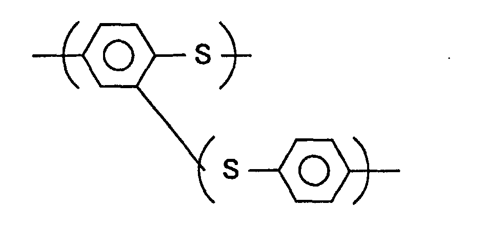
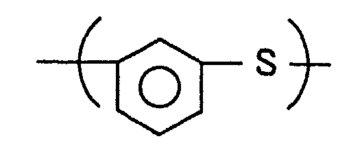
- the polyphenylene sulfide resin (hereinafter referred to as "PPS resin”) contained in the resin composition is, for example, a polymer having 70 mol% or more, preferably 90 mol% or more, of repeated units each represented by the following formula:
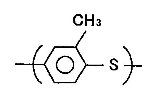
- the PPS resin may further contain 30 mol% or less of repeated units each represented by a selected one of the following formulas:
- the PPS resin contained in the resin composition is a straight-chain polymer having a relatively high molecular weight.
- the PPS resin has a melt flow rate (hereinafter referred to as "MFR") of 250 g/10 min. or lower, preferably 150 g/10 min. as measured at 315.5°C and 49N (5000 g) according to ASTM-D1238.
- MFR melt flow rate
- the PPS resin having such a melting viscosity provides a composition having highly balanced flexibility and impact resistance.
- the olefin based resin contained in the resin composition is a polymer in which olefin is (co)polymerized.
- the olefin based resin may be an olefin polymer, an olefin based polymer, or an olefin based copolymer obtained by incorporating a monomer having a functional group into the olefin based polymer.
- olefin based resin examples include: (a) (co)polymers obtained by polymerizing ⁇ -olefin alone or two or more ⁇ -olefins selected from, for example, ethylene, propylene, butene-1, pentene-1, 4-methylpentene-1, and isobutylene; and (b) copolymers of ⁇ -olefin, and ⁇ , ⁇ -unsaturated acid or alkyl ester thereof, such as acrylic acid, methyl acrylate, ethyl acrylate, butyl acrylate, methacrylic acid, methyl methacrylate, ethyl methacrylate, and butyl methacrylate.
- the resin composition may further contain optional additives, such as a mold releasing agent, a coloring preventive agent, a lubricant, an ultraviolet light inhibitor, an antioxidant, a coloring agent, and a flame retardant.
- optional additives such as a mold releasing agent, a coloring preventive agent, a lubricant, an ultraviolet light inhibitor, an antioxidant, a coloring agent, and a flame retardant.
- the liner for the high pressure container according to the first aspect of the invention may be produced by subjecting the above-described resin composition to injection molding, blow molding, extrusion molding, or the like.
- the liner for the high pressure gas container as described above may be mounted in an automobile using CNG as a fuel. Namely, the liner may be used for a tank that stores the CNG fuel to be supplied to the engine.
- the resin composition used for forming the liner has an Izod impact strength of 500 J/m or greater at 23°C, and, more preferably 600 J/m or greater at 23°C.
- the Izod impact strength mentioned herein is to be interpreted to mean an Izod impact strength measured in a notched Izod impact test according to ASTM-D256.
- the liner for the high pressure gas container exhibits further improved impact resistance, in addition to the improved gas impermeability and pressure resistance as described above. If the Izod impact strength is less than 500 J/m, the impact resistance of the liner may be undesirably reduced.
- the resin composition for forming the liner for the high pressure gas container is obtained by adding about 15 to 50 parts by weight of the olefin based resin to 100 parts by weight of the PPS resin.
- the liner formed of this resin composition provides further improved tensile elongation after fracture and further improved impact resistance, as well as the improved gas impermeability and pressure resistance as described above.
- the resin composition contains about 15 to 42 parts by weight, further preferably about 18 to 40 parts by weight, even more preferably about 20 to 35 parts by weight, of the olefin based resin, with respect to 100 parts by weight of the PPS resin.
- the content of the olefin based resin with respect to 100 parts by weight of the PPS resin is less than 15 parts by weight, the tensile elongation after fracture and impact resistance of the liner may be undesirably reduced. If the content of the olefin based resin with respect to 100 parts by weight of the PPS resin exceeds 50 parts by weight, the methane gas permeability coefficient may be increased, and the relatively high content of the olefin based resin may affect high degrees of heat resistance, thermal stability and chemical resistance that would be otherwise provided by the PPS resin.
- a high pressure gas container including a shell, and a liner disposed on the inner surface of the shell.
- the liner for the high pressure gas container is principally formed of a resin composition containing a polyphenylene sulfide resin and an olefin based resin.
- the resin composition has a methane gas permeability coefficient of 1.7 x 10 -16 mol•m/m 2 •s•Pa or smaller at 40°C, and tensile elongation 50% or greater after fracture at 23°C.
- the high pressure gas container according to the second aspect of the invention uses the liner for the high pressure gas container according to the first aspect of the invention. Therefore, the high pressure gas container exhibits excellent gas impermeability, pressure resistance, and impact resistance. Thus, the thickness of the liner can be advantageously reduced, and the weight of the high pressure gas container can be accordingly reduced.
- the shell may be formed of, for example, a fiber-reinforced plastic obtained by impregnating fibers, such as carbon fibers, aramid fibers, or glass fibers, with a thermosetting resin.
- the fiber-reinforced plastic is a favorable material for forming the shell, in view of adhesion with the liner and its light weight. It is particularly preferable to use a plastic reinforced with carbon fibers, for forming the shell.
- the resin composition used for forming the liner has an Izod impact strength of 500 J/m or greater at 23°C.
- the high pressure gas container exhibits further improved impact resistance, in addition to the improved gas impermeability and pressure resistance as described above.
- the resin composition for forming the liner for the high pressure gas container is obtained by adding about 15 to 50 parts by weight of the olefin based resin to 100 parts by weight of the PPS resin.
- the liner formed of this resin composition provides further improved tensile elongation after fracture and further improved impact resistance, as well as the improved gas impermeability and pressure resistance as described above.
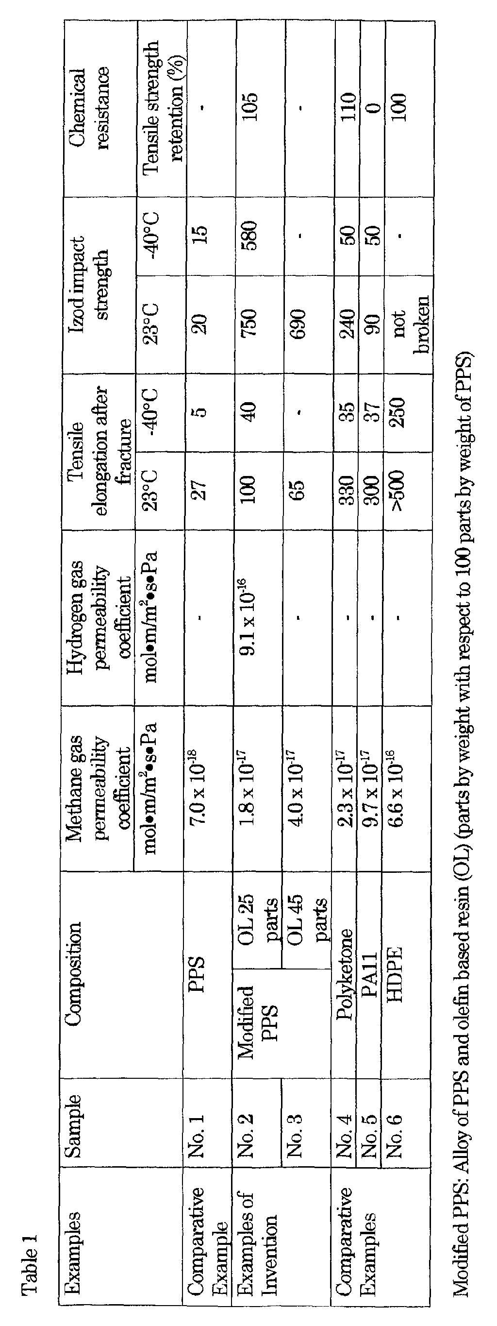
- liners for high pressure gas containers were prepared by using samples No. 1 to No. 6 as indicated just below, and various properties of these examples were measured in the manners as described later.
- Liners formed of the above samples No. 2 and No. 3 provide Examples No. 2 and No. 3 according to the present invention, and liners formed of the other samples Nos. 1, 4, 5 and 6 provide Comparative Examples Nos. 1, 4, 5 and 6, respectively.
- Liners for high pressure gas containers (having a capacity of 7.98 liters) as Examples Nos. 2, 4, 5 and 6 were produced by using Samples Nos. 2, 4, 5 and 6.
- each of the samples was subjected to injection molding, using a mold in which bosses were already inserted, so as provide a half article of the liner. Then, two half articles were opposed to each other, and were subjected to hot plate welding, to thus provide a cylindrical product as shown in FIG. 1.
- the liner for the high pressure gas container thus produced had a thickness of about 7 mm.
- the liner corresponding to each of Examples Nos. 2, 4, 5 and 6 was then covered with a shell made of a fiber-reinforced plastic. More specifically, the shell was produced by winding carbon fibers impregnated with epoxy resin around the outer circumferential surface of the cylindrical liner, so that the thickness of the shell becomes equal to about 10 mm, and then curing the resin in a curing oven at 100°C for 2 hours. In this manner, a high pressure gas container having each of Examples Nos. 2, 4, 5 and 6 was produced.
- Example No. 1 made of PPS and Examples No. 2 and No. 3 containing PPS as a major component provide considerably low methane gas permeability coefficients. It will be also apparent from these tables that Examples No. 2 and No. 3 containing a suitable amount of an olefin based copolymer exhibit improved toughness, more specifically, shows comparatively large tensile elongation after fracture and comparatively high Izod impact strength.
- Example No. 2 and No. 3 provide an excellent balance of the gas impermeability and the toughness as compared with those of Examples Nos. 4 to 6, and are thus favorably used as liners for high pressure gas containers.
- Example No. 2 when used as a liner for a CNG container exhibited lower gas permeability than liners made of other materials.
- the resin compositions of Examples No. 2 and No. 3 according to the invention provide excellent gas impermeability, pressure resistance and impact resistance, and thus are suitably used for forming liners for high pressure gas containers.
- FIG. 1 a liner for a high pressure gas container according to one embodiment of the invention, and a high pressure gas container using such a liner will be hereinafter described in detail.
- the high pressure gas container 7 of this embodiment includes a cylindrical shell 2 as an outer housing, and a liner 1 disposed on the inner surface of the shell 2.
- a gas chamber 10 is defined by the liner 1 within the shell 2.
- bosses 3 are provided at opposite ends of the liner 1, and an opening 30 is formed through a central portion of each of the bosses 3.
- a high pressure gas, such as CNG, is supplied to or discharged from the gas chamber 10 of the container 7, through the opening 30.
- the liner 1 for the high pressure gas container is formed in cylindrical shape in the following manner: a semi-cylindrical product is obtained by injection-molding the composition of Sample 2 as indicated in Tables 1 and 2, and two half articles each having a semi-cylindrical shape are butted and thermally welded together, to provide a cylindrical product.
- the shell 2 is formed by winding fibers impregnated with a thermosetting resin around the outer surface of the liner 1 as the cylindrical product, and thermally curing the thermosetting resin. In this manner, the high pressure gas container is produced.
- the liner 1 for the high pressure gas container may consist of two or three or any suitable number of layers.
- one of the layers that contacts with the shell 2 may be made of the resin composition according to the invention, and the other layer may be made of a resin composition other than those of the invention.
- thermosetting resin used for forming the shell examples include epoxy resin, phenol resin, unsaturated polyester resin, and vinyl ester resin.
- thermosetting resin examples include carbon fibers, aramid fibers, and glass fibers.
Landscapes
- Engineering & Computer Science (AREA)
- Chemical & Material Sciences (AREA)
- Mechanical Engineering (AREA)
- General Engineering & Computer Science (AREA)
- Health & Medical Sciences (AREA)
- Chemical Kinetics & Catalysis (AREA)
- Medicinal Chemistry (AREA)
- Polymers & Plastics (AREA)
- Organic Chemistry (AREA)
- Filling Or Discharging Of Gas Storage Vessels (AREA)
- Pressure Vessels And Lids Thereof (AREA)
- Compositions Of Macromolecular Compounds (AREA)
Abstract
Description




| Gas Permeability of High Pressure Gas Container | ||||
| Examples | Sample No. | Composition | Methane gas permeability cc/liter•hr | |
| Comparative Example | No. 1 | PPS | - | |
| Examples of Invention | No. 2 | Modified PPS | OL 25 parts | 2.7 x 10⁻⁵ |
| No. 3 | OL 45 parts | - | ||
| Comparative Examples | No. 4 | Polyketone | 4.3 x 10⁻⁴ | |
| No. 5 | PA11 | 3.5 x 10⁻⁴ | ||
| No. 6 | HDPE | 3.5 x 10⁻² | ||
| Modified PPS: Alloy of PPS and olefin based resin (OL) (parts by weight with respect to 100 parts by weight of PPS) |
Claims (20)
- A liner for a high pressure gas container, characterized by comprising a resin composition containing a polyphenylene sulfide resin and an olefin based resin,
wherein the resin composition has a methane gas permeability coefficient of 1.7 x 10⁻¹⁶ mol•m/m2•s•Pa or smaller at 40°C, and tensile elongation of 50% or greater after fracture at 23°C. - The liner according to claim 1, wherein the methane gas permeability coefficient of the resin composition is equal to or smaller than 3.3 x 10⁻¹⁷ mol•m/m2•s•Pa at 40°C
- The liner according to claim 2, wherein the methane gas permeability coefficient of the resin composition is equal to or smaller than 2.3 x 10⁻¹⁷ mol•m/m2•s•Pa at 40°C.
- The liner according to any one of claims 1-3, wherein the tensile elongation of the resin composition is equal to or greater than 70% after fracture at 23°C.
- The liner according to any one of claims 1-4, wherein the polyphenylene sulfide resin has a melt flow rate of 250 g/10 min. or lower as measured at 315.5°C and 49N (5000 g) according to ASTM-D1238.
- The liner according to claim any one of claims 1-5, wherein the resin composition has an Izod impact strength of 500 J/m or greater at 23°C.
- The liner according to claim 6, wherein the Izod impact strength of the resin composition measured at 23°C is equal to or greater than 600 J/m.
- The liner according to any one of claims 1-7, wherein the resin composition contains about 15 to 50 parts by weight of the olefin based resin with respect to 100 parts by weight of the polyphenylene sulfide resin.
- The liner according to claim 8, wherein the resin composition contains about 18 to 40 parts by weight of the olefin based resin with respect to 100 parts by weight of the polyphenylene sulfide resin.
- The liner according to claim 9, wherein the resin composition contains about 20 to 35 parts by weight of the olefin based resin with respect to 100 parts by weight of the polyphenylene sulfide resin.
- A liner for a compressed natural gas container, characterized by comprising a resin composition containing a polyphenylene sulfide resin and an olefin based resin,
wherein the resin composition has a methane gas permeability coefficient of 3.3 x 10⁻¹⁷ mol•m/m2•s•Pa or smaller at 40°C, and tensile elongation of 50% or greater after fracture at 23°C. - The liner according to claim 11, wherein the resin composition has an Izod impact strength of 500 J/m or greater at 23°C.
- The liner according to claim 11 or claim 12, wherein the resin composition contains about 15 to 42 parts by weight of the olefin based resin with respect to 100 parts by weight of the polyphenylene sulfide resin.
- A high pressure gas container (7), including a shell (2), and a liner (1) disposed on an inner surface of the shell (2), characterized in that:the liner comprises a resin composition containing a polyphenylene sulfide resin and an olefin based resin; and thatthe resin composition has a methane gas permeability coefficient of 1.7 x 10⁻¹⁶ mol•m/m2•s•Pa or smaller at 40°C, and tensile elongation 50% or greater after fracture at 23°C.
- The high pressure gas container according to claim 14, wherein the methane gas permeability coefficient of the resin composition is equal to or smaller than 3.3 x 10⁻¹⁷ mol•m/m2•s•Pa at 40°C.
- The high pressure gas container according to claim 14 or claim 15, wherein the tensile elongation of the resin composition is equal to or greater than 70% after fracture at 23°C.
- The high pressure gas container according to any one of claims 14-16, wherein the resin composition has an Izod impact strength of 500 J/m or greater at 23°C.
- The high pressure gas container according to any one of claims 14-17, wherein the resin composition contains about 15 to 50 parts by weight of the olefin based resin with respect to 100 parts by weight of the PPS resin.
- The high pressure gas container according to any one of claims 14-18, wherein the shell comprises a fiber-reinforced plastic obtained by impregnating fibers with a thermosetting resin.
- The high pressure gas container according to claim 19, wherein the fibers are selected from the group consisting of carbon fibers, aramid fibers, and glass fibers.
Applications Claiming Priority (4)
| Application Number | Priority Date | Filing Date | Title |
|---|---|---|---|
| JP2001023453 | 2001-01-31 | ||
| JP2001023453 | 2001-01-31 | ||
| JP2001383434 | 2001-12-17 | ||
| JP2001383434A JP4049580B2 (en) | 2001-01-31 | 2001-12-17 | High pressure gas container liner and high pressure gas container |
Publications (2)
| Publication Number | Publication Date |
|---|---|
| EP1228862A1 true EP1228862A1 (en) | 2002-08-07 |
| EP1228862B1 EP1228862B1 (en) | 2006-08-09 |
Family
ID=26608622
Family Applications (1)
| Application Number | Title | Priority Date | Filing Date |
|---|---|---|---|
| EP20020001919 Expired - Lifetime EP1228862B1 (en) | 2001-01-31 | 2002-01-31 | Liner for high pressure gas container and high pressure gas container |
Country Status (4)
| Country | Link |
|---|---|
| US (1) | US7208207B2 (en) |
| EP (1) | EP1228862B1 (en) |
| JP (1) | JP4049580B2 (en) |
| DE (1) | DE60213690T8 (en) |
Cited By (2)
| Publication number | Priority date | Publication date | Assignee | Title |
|---|---|---|---|---|
| US8053523B2 (en) | 2008-02-12 | 2011-11-08 | Ube Industries, Ltd. | Hydrogen tank liner material and hydrogen tank liner |
| WO2024012891A1 (en) * | 2022-07-15 | 2024-01-18 | Schott Ag | Hydrogen store |
Families Citing this family (33)
| Publication number | Priority date | Publication date | Assignee | Title |
|---|---|---|---|---|
| JP4596787B2 (en) * | 2003-04-25 | 2010-12-15 | 豊田合成株式会社 | Fuel tank |
| DE10352437A1 (en) * | 2003-11-10 | 2005-06-16 | Wagner Alarm- Und Sicherungssysteme Gmbh | Device for preventing and extinguishing fires |
| JP4552434B2 (en) * | 2003-12-19 | 2010-09-29 | Dic株式会社 | Multilayer molded body |
| US7506778B2 (en) * | 2004-01-09 | 2009-03-24 | Kazak Composities, Incorporated | Modular packaging system |
| DE102004044541B4 (en) * | 2004-09-15 | 2007-04-05 | DRäGER AEROSPACE GMBH | Compressed gas tank and a bulletproof sheath for a pressure vessel |
| JP4849324B2 (en) * | 2006-08-15 | 2012-01-11 | トヨタ自動車株式会社 | High pressure tank |
| US20080284062A1 (en) * | 2007-05-04 | 2008-11-20 | Simpson Peter J | Injection molded doll head |
| EP2058527A3 (en) * | 2007-11-08 | 2012-05-30 | Parker-Hannifin Corporation | Lightweight high pressure repairable piston composite accumulator with slip flange |
| EP2060797A3 (en) | 2007-11-13 | 2012-11-14 | Parker-Hannifin Corporation | Lightweight high pressure repairable piston tie rod composite accumulator |
| JP4865833B2 (en) * | 2009-04-30 | 2012-02-01 | 三菱重工業株式会社 | Tube for pressure transducer |
| US20110226782A1 (en) * | 2010-03-17 | 2011-09-22 | Gm Global Technology Operations, Inc. | Gas temperature moderation within compressed gas vessel through heat exchanger |
| EP2625455B1 (en) * | 2010-10-04 | 2021-12-08 | AMTROL Licensing Inc. | Support stand for pressure vessel |
| US8647457B2 (en) | 2011-07-28 | 2014-02-11 | Chung-Shan Institute of Science and Technology, Armaments, Bureau, Ministry of National Defense | Method of manufacturing rubber lined composite pressure vessels |
| WO2013083176A2 (en) * | 2011-12-05 | 2013-06-13 | Blue Wave Co S.A. | Fire resistant pressure vessel |
| US9494260B2 (en) | 2012-04-13 | 2016-11-15 | Ticona Llc | Dynamically vulcanized polyarylene sulfide composition |
| US9493646B2 (en) | 2012-04-13 | 2016-11-15 | Ticona Llc | Blow molded thermoplastic composition |
| US9758674B2 (en) | 2012-04-13 | 2017-09-12 | Ticona Llc | Polyarylene sulfide for oil and gas flowlines |
| US9494262B2 (en) | 2012-04-13 | 2016-11-15 | Ticona Llc | Automotive fuel lines including a polyarylene sulfide |
| US9765219B2 (en) | 2012-04-13 | 2017-09-19 | Ticona Llc | Polyarylene sulfide components for heavy duty trucks |
| CN102748583A (en) * | 2012-07-27 | 2012-10-24 | 林学优 | Composite type anti-explosion high-pressure air cylinder |
| JP5936642B2 (en) * | 2013-04-17 | 2016-06-22 | 豊田合成株式会社 | Pressure vessel liner, mold thereof, and pressure vessel |
| US8881932B1 (en) * | 2013-06-25 | 2014-11-11 | Quantum Fuel Systems Technology Worldwide, Inc. | Adapterless closure assembly for composite pressure vessels |
| WO2015031232A1 (en) | 2013-08-27 | 2015-03-05 | Ticona Llc | Thermoplastic composition with low hydrocarbon uptake |
| JP6626444B2 (en) | 2013-08-27 | 2019-12-25 | ティコナ・エルエルシー | Heat resistant reinforced thermoplastic composition for injection molding |
| EP2902692B1 (en) | 2013-12-06 | 2017-10-25 | MAGNA STEYR Engineering AG & Co KG | Component of a tank system |
| US11353160B2 (en) * | 2014-02-27 | 2022-06-07 | Hanwha Cimarron Llc | Pressure vessel |
| WO2016094381A1 (en) | 2014-12-11 | 2016-06-16 | Ticona Llc | Stabilized flexible thermoplastic composition and products formed therefrom |
| JP6123933B2 (en) * | 2016-04-19 | 2017-05-10 | トヨタ自動車株式会社 | High-pressure tank and method for manufacturing high-pressure tank |
| US11440399B2 (en) | 2019-03-22 | 2022-09-13 | Agility Fuel Systems Llc | Fuel system mountable to a vehicle frame |
| US20200347992A1 (en) | 2019-05-02 | 2020-11-05 | Agility Fuel Systems Llc | Polymeric liner based gas cylinder with reduced permeability |
| JP7757802B2 (en) * | 2021-02-04 | 2025-10-22 | 東レ株式会社 | pressure vessel |
| US12358365B1 (en) | 2021-05-07 | 2025-07-15 | Agility Fuel Systems Llc | Vehicles having composite interwoven gas containment assemblies |
| EP4291818A4 (en) | 2021-05-07 | 2025-01-08 | Agility Fuel Systems LLC | COMPOSITE INTERLACED GAS CONTAINMENT ASSEMBLIES |
Citations (11)
| Publication number | Priority date | Publication date | Assignee | Title |
|---|---|---|---|---|
| US5025943A (en) * | 1988-03-15 | 1991-06-25 | Abb Plast Ab | Pressure vessel having a filamentary wound structure |
| JPH03236930A (en) * | 1990-02-13 | 1991-10-22 | Toray Ind Inc | Blow hollow molded product |
| JPH05124090A (en) * | 1991-11-07 | 1993-05-21 | Toray Ind Inc | Blow molding |
| US5227427A (en) * | 1990-12-17 | 1993-07-13 | Polyplastics Co., Ltd. | Polyarylene sulfide resin composition and process for the preparation of the same |
| JPH06190980A (en) * | 1992-12-25 | 1994-07-12 | Toray Ind Inc | Laminated structure |
| JPH09257193A (en) * | 1996-03-22 | 1997-09-30 | Toray Ind Inc | Pressure vessel and manufacturing method thereof |
| JPH10231997A (en) * | 1997-02-18 | 1998-09-02 | Toyoda Gosei Co Ltd | Pressure vessel and its manufacture |
| EP0888880A1 (en) * | 1996-12-16 | 1999-01-07 | Toray Industries, Inc. | Conductive multilayer blow molding and conductive resin composition |
| EP0900650A1 (en) * | 1996-11-08 | 1999-03-10 | Toray Industries, Inc. | Multi-layer moldings and polyphenylene sulfide resin composition |
| WO2001027204A1 (en) * | 1999-10-12 | 2001-04-19 | Toray Industries, Inc. | Resin structure and use thereof |
| JP2001226537A (en) * | 2000-02-17 | 2001-08-21 | Toray Ind Inc | Thermoplastic resin structure and molded product |
Family Cites Families (10)
| Publication number | Priority date | Publication date | Assignee | Title |
|---|---|---|---|---|
| IT1185613B (en) * | 1985-05-30 | 1987-11-12 | Magnaghi Cleodinamica Spa | GAS-OIL PRESSURE ACCUMULATOR WITH COMPOSITE MATERIAL STRUCTURE FOR AIRCRAFT HYDRAULIC CIRCUITS |
| US5187257A (en) * | 1987-04-24 | 1993-02-16 | Kureha Kagaku Kogyo Kabushiki Kaisha | Thermoformed polyarylene sulfide container |
| GB8818622D0 (en) * | 1988-08-05 | 1988-09-07 | British Petroleum Co Plc | Container for high pressure gases |
| JPH06299071A (en) | 1993-04-12 | 1994-10-25 | Dainippon Ink & Chem Inc | Thermoplastic resin composition |
| US5499739A (en) * | 1994-01-19 | 1996-03-19 | Atlantic Research Corporation | Thermoplastic liner for and method of overwrapping high pressure vessels |
| CA2168794A1 (en) * | 1994-06-09 | 1995-12-14 | Takayuki Araki | Fluoroolefin, fluoropolymer, and thermoplastic resin composition containing the polymer |
| JP3540921B2 (en) * | 1997-09-18 | 2004-07-07 | 豊田合成株式会社 | Resin molding |
| JP3739954B2 (en) | 1998-10-26 | 2006-01-25 | 東レ株式会社 | Polyphenylene sulfide resin composition |
| JP3811012B2 (en) * | 2001-01-31 | 2006-08-16 | 豊田合成株式会社 | Fuel system parts |
| JP4596787B2 (en) * | 2003-04-25 | 2010-12-15 | 豊田合成株式会社 | Fuel tank |
-
2001
- 2001-12-17 JP JP2001383434A patent/JP4049580B2/en not_active Expired - Fee Related
-
2002
- 2002-01-31 US US10/059,267 patent/US7208207B2/en not_active Expired - Fee Related
- 2002-01-31 EP EP20020001919 patent/EP1228862B1/en not_active Expired - Lifetime
- 2002-01-31 DE DE2002613690 patent/DE60213690T8/en active Active
Patent Citations (11)
| Publication number | Priority date | Publication date | Assignee | Title |
|---|---|---|---|---|
| US5025943A (en) * | 1988-03-15 | 1991-06-25 | Abb Plast Ab | Pressure vessel having a filamentary wound structure |
| JPH03236930A (en) * | 1990-02-13 | 1991-10-22 | Toray Ind Inc | Blow hollow molded product |
| US5227427A (en) * | 1990-12-17 | 1993-07-13 | Polyplastics Co., Ltd. | Polyarylene sulfide resin composition and process for the preparation of the same |
| JPH05124090A (en) * | 1991-11-07 | 1993-05-21 | Toray Ind Inc | Blow molding |
| JPH06190980A (en) * | 1992-12-25 | 1994-07-12 | Toray Ind Inc | Laminated structure |
| JPH09257193A (en) * | 1996-03-22 | 1997-09-30 | Toray Ind Inc | Pressure vessel and manufacturing method thereof |
| EP0900650A1 (en) * | 1996-11-08 | 1999-03-10 | Toray Industries, Inc. | Multi-layer moldings and polyphenylene sulfide resin composition |
| EP0888880A1 (en) * | 1996-12-16 | 1999-01-07 | Toray Industries, Inc. | Conductive multilayer blow molding and conductive resin composition |
| JPH10231997A (en) * | 1997-02-18 | 1998-09-02 | Toyoda Gosei Co Ltd | Pressure vessel and its manufacture |
| WO2001027204A1 (en) * | 1999-10-12 | 2001-04-19 | Toray Industries, Inc. | Resin structure and use thereof |
| JP2001226537A (en) * | 2000-02-17 | 2001-08-21 | Toray Ind Inc | Thermoplastic resin structure and molded product |
Non-Patent Citations (7)
| Title |
|---|
| DATABASE WPI Section Ch Week 199148, Derwent World Patents Index; Class A17, AN 1991-351188, XP002195582 * |
| DATABASE WPI Section Ch Week 199325, Derwent World Patents Index; Class A17, AN 1993-200141, XP002195475 * |
| DATABASE WPI Section Ch Week 200128, Derwent World Patents Index; Class A17, AN 2001-273757, XP002195472 * |
| PATENT ABSTRACTS OF JAPAN vol. 018, no. 543 (M - 1687) 17 October 1994 (1994-10-17) * |
| PATENT ABSTRACTS OF JAPAN vol. 1998, no. 01 30 January 1998 (1998-01-30) * |
| PATENT ABSTRACTS OF JAPAN vol. 1998, no. 14 31 December 1998 (1998-12-31) * |
| PATENT ABSTRACTS OF JAPAN vol. 2000, no. 25 12 April 2001 (2001-04-12) * |
Cited By (2)
| Publication number | Priority date | Publication date | Assignee | Title |
|---|---|---|---|---|
| US8053523B2 (en) | 2008-02-12 | 2011-11-08 | Ube Industries, Ltd. | Hydrogen tank liner material and hydrogen tank liner |
| WO2024012891A1 (en) * | 2022-07-15 | 2024-01-18 | Schott Ag | Hydrogen store |
Also Published As
| Publication number | Publication date |
|---|---|
| JP2003056702A (en) | 2003-02-26 |
| JP4049580B2 (en) | 2008-02-20 |
| EP1228862B1 (en) | 2006-08-09 |
| DE60213690T8 (en) | 2008-01-31 |
| US7208207B2 (en) | 2007-04-24 |
| US20020150746A1 (en) | 2002-10-17 |
| DE60213690T2 (en) | 2007-08-16 |
| DE60213690D1 (en) | 2006-09-21 |
Similar Documents
| Publication | Publication Date | Title |
|---|---|---|
| US7208207B2 (en) | Liner for high pressure gas container and high pressure gas container | |
| US9470366B2 (en) | Liner for gas storage tank | |
| US8153215B1 (en) | Multilayer structure based on polyamides and tube or conduit with multilayer structure | |
| CN115413292A (en) | Multilayer structure for transporting or storing hydrogen | |
| KR100948529B1 (en) | Multi-layered structure based on connecting layers made of polyamide and copolyamide blend | |
| EP4633936A1 (en) | Multilayer structure and articles for the storage and transportation of gasses | |
| JP3367679B2 (en) | Multi-layer structure based on plastic and tube having multi-layer structure | |
| EP1571174A1 (en) | Material for fuel-system part and fuel-system part comprising the same | |
| KR20240027092A (en) | Multi-layer structures for transporting or storing hydrogen | |
| EP1817378B1 (en) | Alloy composition useful for fluid transport objects | |
| US12485657B2 (en) | Multi-layer structure for storing hydrogen | |
| US7049006B2 (en) | Multilayer structure based on polyamides and on a tie layer made of a copolyamide blend | |
| KR20260019540A (en) | Polyamide composition and polar graphene | |
| WO2017103502A1 (en) | Barrier structure based on mpmdt/xt copolyamide with a high tg | |
| JP2023511975A (en) | Multi-layer structure for transporting or storing hydrogen | |
| US11351762B2 (en) | Barrier structure made from MXDT/XT copolyamide with a high Tg | |
| US20250083373A1 (en) | Blow molding compositions based on branched polyamides and uses thereof | |
| EP4633935A1 (en) | Multilayer structure and articles for the storage and transportation of gasses | |
| KR20250124813A (en) | Gas storage containers |
Legal Events
| Date | Code | Title | Description |
|---|---|---|---|
| PUAI | Public reference made under article 153(3) epc to a published international application that has entered the european phase |
Free format text: ORIGINAL CODE: 0009012 |
|
| 17P | Request for examination filed |
Effective date: 20020131 |
|
| AK | Designated contracting states |
Kind code of ref document: A1 Designated state(s): AT BE CH CY DE DK ES FI FR GB GR IE IT LI LU MC NL PT SE TR |
|
| AX | Request for extension of the european patent |
Free format text: AL;LT;LV;MK;RO;SI |
|
| AKX | Designation fees paid |
Designated state(s): DE FR GB |
|
| 17Q | First examination report despatched |
Effective date: 20041222 |
|
| GRAP | Despatch of communication of intention to grant a patent |
Free format text: ORIGINAL CODE: EPIDOSNIGR1 |
|
| GRAS | Grant fee paid |
Free format text: ORIGINAL CODE: EPIDOSNIGR3 |
|
| GRAA | (expected) grant |
Free format text: ORIGINAL CODE: 0009210 |
|
| RIN1 | Information on inventor provided before grant (corrected) |
Inventor name: ISHIKAWA, TAKASHI,TOYOTA JIDOSHA K. K. Inventor name: KATO, TSUYOSHI,TOYODA GOSEI CO., LTD. Inventor name: KONDO, KUNIYOSHI,TOYODA GOSEI CO., LTD. Inventor name: KAMIYA, ITSUO,TOYOTA JIDOSHA K. K. Inventor name: SUZUKI, TETSUYA,TOYODA GOSEI CO., LTD. Inventor name: NISHIMURA, YASUHIRO,TOYODA GOSEI CO., LTD. Inventor name: ONO, SATORU,TOYODA GOSEI CO., LTD. Inventor name: TAKENAKA, KEIJI,TOYODA GOSEI CO., LTD. Inventor name: SHIMOJIMA, SHINGO,TOYODA GOSEI CO., LTD. Inventor name: KOIZUMI, JUNJI,TOYODA GOSEI CO., LTD. Inventor name: SHIMIZU, HIROKAZU,TOYOTA JIDOSHA K. K. |
|
| RAP1 | Party data changed (applicant data changed or rights of an application transferred) |
Owner name: TOYODA GOSEI CO., LTD. Owner name: TOYOTA JIDOSHA KABUSHIKI KAISHA |
|
| AK | Designated contracting states |
Kind code of ref document: B1 Designated state(s): DE FR GB |
|
| REG | Reference to a national code |
Ref country code: GB Ref legal event code: FG4D |
|
| REF | Corresponds to: |
Ref document number: 60213690 Country of ref document: DE Date of ref document: 20060921 Kind code of ref document: P |
|
| ET | Fr: translation filed | ||
| PLBE | No opposition filed within time limit |
Free format text: ORIGINAL CODE: 0009261 |
|
| STAA | Information on the status of an ep patent application or granted ep patent |
Free format text: STATUS: NO OPPOSITION FILED WITHIN TIME LIMIT |
|
| 26N | No opposition filed |
Effective date: 20070510 |
|
| PGFP | Annual fee paid to national office [announced via postgrant information from national office to epo] |
Ref country code: DE Payment date: 20110126 Year of fee payment: 10 Ref country code: FR Payment date: 20110128 Year of fee payment: 10 |
|
| PGFP | Annual fee paid to national office [announced via postgrant information from national office to epo] |
Ref country code: GB Payment date: 20110126 Year of fee payment: 10 |
|
| GBPC | Gb: european patent ceased through non-payment of renewal fee |
Effective date: 20120131 |
|
| REG | Reference to a national code |
Ref country code: FR Ref legal event code: ST Effective date: 20120928 |
|
| PG25 | Lapsed in a contracting state [announced via postgrant information from national office to epo] |
Ref country code: DE Free format text: LAPSE BECAUSE OF NON-PAYMENT OF DUE FEES Effective date: 20120801 Ref country code: GB Free format text: LAPSE BECAUSE OF NON-PAYMENT OF DUE FEES Effective date: 20120131 |
|
| REG | Reference to a national code |
Ref country code: DE Ref legal event code: R119 Ref document number: 60213690 Country of ref document: DE Effective date: 20120801 |
|
| PG25 | Lapsed in a contracting state [announced via postgrant information from national office to epo] |
Ref country code: FR Free format text: LAPSE BECAUSE OF NON-PAYMENT OF DUE FEES Effective date: 20120131 |