EP1228822B1 - Press brake and ram movement method for press brake - Google Patents
Press brake and ram movement method for press brake Download PDFInfo
- Publication number
- EP1228822B1 EP1228822B1 EP00969901A EP00969901A EP1228822B1 EP 1228822 B1 EP1228822 B1 EP 1228822B1 EP 00969901 A EP00969901 A EP 00969901A EP 00969901 A EP00969901 A EP 00969901A EP 1228822 B1 EP1228822 B1 EP 1228822B1
- Authority
- EP
- European Patent Office
- Prior art keywords
- servo motor
- hydraulic
- fluid pump
- cylinder
- cylinder chamber
- Prior art date
- Legal status (The legal status is an assumption and is not a legal conclusion. Google has not performed a legal analysis and makes no representation as to the accuracy of the status listed.)
- Expired - Lifetime
Links
Images


Classifications
-
- B—PERFORMING OPERATIONS; TRANSPORTING
- B21—MECHANICAL METAL-WORKING WITHOUT ESSENTIALLY REMOVING MATERIAL; PUNCHING METAL
- B21D—WORKING OR PROCESSING OF SHEET METAL OR METAL TUBES, RODS OR PROFILES WITHOUT ESSENTIALLY REMOVING MATERIAL; PUNCHING METAL
- B21D5/00—Bending sheet metal along straight lines, e.g. to form simple curves
- B21D5/02—Bending sheet metal along straight lines, e.g. to form simple curves on press brakes without making use of clamping means
Definitions
- This invention relates to a press brake according to the preamble of claim 1 and a ram moving method in a press brake for performing a bending work by relatively moving an upper table or a lower table upward and downward.
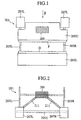
- a conventionally general hydraulic press brake 201 has side plates 203L and 203R provided in a standing manner left and right, has an upper table 205U on upper front end surfaces of the side plates 203L and 203R so as to freely move upward and downward, and is provided with a lower table 205L on lower front surfaces of the side plates 203L and 203R in a fixed manner.
- hydraulic cylinders 207L and 207R for moving the upper table 205U upward and downward are provided in the upper front surfaces of the side plates 203L and 203R, and a hydraulic equipment 209 such as a pump, an oil tank, a control valve and the like for controlling each of the hydraulic cylinders 207L and 207R is provided in a rear portion of a center portion of the press brake 201 in a lump and is connected to each of the hydraulic cylinders 207L and 207R by a piping 211.
- a punch P is provided in a lower end portion of the upper table 205U so as to be freely replaced
- a die D is provided in an upper end portion of the lower table 205L so as to be freely replaced.
- a bending work is applied to a work positioned between the punch P and the die D on the basis of a cooperation between the punch P and the die D by driving the respective hydraulic cylinders 207L and 207R according to a control of the hydraulic equipment 209 so as to move the upper table 205U upward and downward.
- a working fluid in the oil tank is sucked into the hydraulic cylinders 207L and 207R by utilizing its own weight of the upper table 205U at a time of rapidly dropping, however, a temperature of the working fluid is low at a time of starting the process and a viscosity thereof is high, whereby a sufficient speed can not be obtained due to generation of suction lack or a cavitation is generated, so that there is a problem of a risk that a performance decrement is involved.
- a temperature of a frame is increased due to the heat generation, a heat deformation is generated in the frame, and a reduction of bending work accuracy is caused.
- an upper cylinder chamber 305U of the hydraulic cylinder 303 is connected to a switch valve 311 by a piping 307, and a lower cylinder chamber 305L is connected to the switch valve 311 by a piping 309.
- This switch valve 311 is connected to an oil tank 315 by a piping 313 and connected to the oil tank 315 via a hydraulic pump 319 by a piping 317.
- the hydraulic pump 319 is driven, for example, by an AC servo motor 321.
- the hydraulic pump 319 in the case of moving a piston 323 upward, the hydraulic pump 319 is rotated by the AC servo motor 321, and the switch valve 311 is moved from a state shown in Fig. 3 to a left direction. Accordingly, a working fluid is discharged from the oil tank 315 by the hydraulic pump 319 so as to be supplied to the lower cylinder chamber 305L, and the working fluid in the upper cylinder chamber 305U is returned to the oil tank 315 through the switch valve 311.
- the switch valve 311 vibrates due to a strong external force at a time of discharging the working fluid at a high pressure, and there is a risk that a vibration is generated in the upper table 301U corresponding to the ram. Further, as shown in Fig. 4. since a "opening degree - flow rate" property of the switch valve 311 is different between an unload time (a low pressure time) and a load time (a high pressure time), there is a risk that a motion gain of the ram is changed so as to generate the vibration. Accordingly, since the structure is made such as to make a ram speed at a time of depressure slow so as to reduce generation of the vibration, there is a problem that a productivity is deteriorated.
- a press brake according to the preamble of claim 1 is known from JP-A-10 180499. This known press brake exhibits the drawback that is does not achieve a satisfactory accuracy of bending work.
- This invention is made by paying attention to the problems in the prior art mentioned above.
- an object of this invention is to provide a press brake which can prevent an increase of oil temperature and can make an apparatus compact by widely reducing a capacity of an oil tank.
- Another object of this invention is to provide a press brake which can reduce a shock at a time of depressure so as to prevent a vibration, and can increase a ram speed so as to improve a productivity.
- Still another object of this invention is to provide a ram moving method in a press brake which can reduce a shock at a time of depressure so as to prevent a vibration, and can increase a ram speed so as to improve a productivity.
- a press brake as defined in claim 1 and a ram moving method as defined in claim 7 is provided.
- a bending work is performed by relatively moving the upper table or the lower table upward and downward by means of a plurality of hydraulic cylinders, however, at this time, the respective hydraulic cylinders are driven by individually controlling the two-way fluid pumps and the respective hydraulic devices which are provided in correspondence to the respective hydraulic cylinders. Further, the crowing cylinder provided in the lower table is also driven by individually controlling the two-way fluid pump and the hydraulic device which are provided in correspondence to the crowning cylinder.
- a preferred embodiment of the inventive press brake is defined in claim 2.
- the respective two-way fluid pumps corresponding to a plurality of hydraulic cylinders for relatively moving the upper table or the lower table upward and downward, and the respective hydraulic devices are mounted to the base plate mounted to the upper portion of the respective hydraulic cylinders, and the oil tank is provided in the upper side of the hydraulic devices.
- the present invention it is possible to make the piping short. Accordingly, it is possible to make a piping operation easy, it is possible to reduce an oil leak and it is possible to make a pressure loss small so as to improve a controllability. Further, since a distance between the hydraulic cylinder and the oil tank is short, it is easy to suck the working fluid from the oil tank at a time when the upper table or the lower table moves downward, so that it is possible to perform a rapid downward movement without generating a suction lack of the working fluid.
- the bending work is performed by operating the two-way fluid pumps provided in correspondence to the respective hydraulic cylinders by the servo motor and supplying the working fluid to one of the upper cylinder chambers and the lower cylinder chambers in the respective hydraulic cylinders so as to move the ram upward and downward.
- the order unit gives the order of reverse rotation to the servo motor so as to reverse rotate the servo motor and reverse rotate the two-way fluid pumps, thereby supplying the working fluid in the one cylinder chamber to another cylinder chamber so as to switch the vertical movement of the ram.
- the present invention it is not necessary to employ the conventional switch valve. Accordingly, since it is possible to reduce the shock at a time of depressure, and it is possible to increase a ram speed at a time of depressure, it is possible to improve a productivity. Further, since no switch valve is provided, it is possible to prevent the conventional vibration from being generated by the switch valve. Further, since a flow rate property is not affected by the pressure, a motion gain of the ram is not changed so much, so that it is possible to prevent the vibration due to the change of the flow rate property against the pressure.
- the inventive ram moving method as defined in claim 7 it is possible to reduce the shock at a time of depressure and it is possible to increase the ram speed at a time of depressure, it is possible to improve the productivity. Further, since no switch valve is provided, it is possible to prevent the conventional vibration from being generated by the switch valve. Further, since a flow rate property is not affected by the pressure, a motion gain of the ram is not changed so much, so that it is possible to prevent the vibration due to the change of the flow rate property against the pressure.
- inventive press brake and the inventive ram moving method are defined in dependent sub-claims 4-6 and dependent claim 8, respectively.
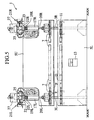
- FIGs. 5 and 6 there is shown a whole of a press brake 1 according to this invention.
- This press brake 1 has side plates 3L and 3R provided so as to be stood in left and right sides, is provided with an upper table 5U serving as a first table on front end surfaces of upper portions in the side plates 3L and 3R so as to freely move upward and downward, and is provided with a lower table 5L serving as a second table on front surfaces of lower portions in the side plates 3L and 3R.
- a punch P is provided in a lower end portion of the upper table 5U by a bolt 9 via an intermediate plate 7 so as to be freely replaced. Further, a die D is provided in an upper end portion of the lower table 5L via a die base 11 so as to be freely replaced.
- Both end portions of the lower table 5L are fixed to the side plates 3L and 3R, however, a center portion thereof can be lifted upward only at a little amount, and is provided with a crowning cylinder 13 for modifying a downward displacement of the lower table 5L and the die D to an upward direction at a time of bending work so as to easily pass the die D therethrough.
- a linear scale 15 for measuring a position of height of the upper table 5U is provided, and a detection of bending angle, a security and the like are performed by determining an interval with respect to the die D on the basis of the height of the punch P.
- Hydraulic cylinders 17L and 17R are respectively provided in the front surfaces of the upper portions in the left and right side plates 3L and 3R, and the upper table 5U mentioned above is mounted to piston rods 20L and 20R attached to pistons 19L and 19R of the hydraulic cylinders 17L and 17R.
- the hydraulic cylinders 17L and 17R provided in the left and right side plates 3L and 3R, and hydraulic devices 21L and 21R controlling the hydraulic cylinders 17L and 17R include a pair of left and right linear scales, a pair of left and right two-way pumps, and a pair of left and right AC servo motors, and the same elements are independently provided in the left and right sides. Accordingly, a description will be given only of the hydraulic cylinder 17R and the hydraulic device 21R which are provided in the right side plate 3R as follows.
- a base plate 23 is mounted to an upper side of a cylinder head 22R of the hydraulic cylinder 17R and an upper end surface of the side plate 3R, and the hydraulic device 21R is provided on an upper surface of the base plate 23.
- a prefill valve 25 is provided in an upper portion of the hydraulic cylinder 17R on the upper surface of the base plate 23, and an oil tank 27 is provided on the prefill valve 25.
- a manifold 29 or the like is provided on the upper surface of the base plate 23 in a rearward portion (in a right direction in Fig. 6) of the prefill valve 25, and a two-way piston 31 corresponding to a two-way fluid pump and, for example, an AC servo motor 33 corresponding to a servo motor for driving the two-way piston pump 31 are provided in a rearward portion of the upper portion of the side plate 3R.
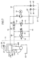
- An upper cylinder chamber 35U of the hydraulic cylinder 17R for moving the upper table 5U corresponding to the ram upward and downward is connected to the prefill valve 25 of the hydraulic device 21R provided in the upper portion of the hydraulic cylinder 17R by a piping 37, and is further connected to the oil tank 27 provided in the upper side of the hydraulic cylinder 17R by a piping 39.
- the upper cylinder chamber 35U mentioned above is connected to one side of a two-way piston pump 31 capable of rotating in two directions by a piping 41.
- a piping 43 is connected to a middle of the piping 41, and is connected to the oil tank 27 via a check valve 45 and a suction filter 47.
- the two-way piston pump 31 is rotated by the AC servo motor 33.
- a piping 49 is connected to a lower cylinder chamber 35L of the hydraulic cylinder 17R, and a counter balance valve 51 and a sequence switch valve 53 corresponding to an electromagnetic poppet valve are provided in parallel.
- the counter balance valve 51 and the sequence switch valve 53 are connected to another side of the two-way piston pump 31 by a piping 55.
- the piping 55 is connected to the oil tank 27 via a check valve 57 and a suction filter 59 by a piping 61.
- a throttle valve 63 and a high pressure preference type shuttle valve 65 are provided in the middle of the piping 49.
- a piping 67 is connected to a discharge side of the high pressure preference type shuttle valve 65, and a relief valve 69 and a piping 71 are provided in the piping 67.
- the two-way piston pump 31 stops and the piston 19R rapidly moves the upper table 5U downward from a state of being at a top dead center due to its own weight of the upper table 5U and the hydraulic cylinder 17R, the piping 49 and the piping 55 are communicated by switching the sequence switch valve 53, and the two-way piston pump 31 is rotated by the AC servo motor 33.
- the sequence switch valve 53 is set to a state shown in Fig. 7, and the working fluid from the lower cylinder chamber 35L is charged into the upper cylinder chamber 35U of the hydraulic cylinder 17R from the piping 41 via the piping 49, the counter balance valve 51 and the piping 55 by the two-way piston pump 31. Accordingly, the piston 19R moves downward and the upper table 5U moves downward, thereby performing the bending work.
- the prefill valve 25 is opened according to a pilot signal 73, and the working fluid is discharged to the oil tank 27 from the upper cylinder chamber 35U through the prefill valve 25.
- the hydraulic device 21R such as the oil tank 27, the two-way piston pump 31, the AC servo motor 33 and the like is provided close to the upper side of the hydraulic cylinder 17R, it is possible to make the piping short, and it is possible to make a wiring operation easy. Further, it is possible to reduce an oil leak and it is possible to improve a controllability by reducing a pressure loss.
- the two-way piston pump 31 is rotated by the AC servo motor 33 capable of performing a control with high precision, it is possible to control the hydraulic pressure with high precision, and it is possible to improve an accuracy of bending work.
- Fig. 8 shows a hydraulic circuit of the crowning cylinder 13.
- a piping 77 is connected to a lower cylinder chamber 75 of the crowning cylinder 13, and the piping 77 is connected to the oil tank 27 via a two-way piston pump 81 rotated by an AC servo motor 79. Further, the piping 77 is connected to the oil tank 27 via a relief valve 83.
- the center of the lower table 5L is lifted up by rotating the two-way piston pump 81 by the AC servo motor 79 and supplying the working fluid to the lower cylinder chamber 75 of the crowning cylinder 13 so as to move a piston 85 upward, thereby modifying pass-through of the die D. Further, in the case of moving the piston 85 downward, the two-way piston pump 81 is reverse rotated by the AC servo motor 79, and the working fluid in the lower cylinder chamber 75 is discharged into the oil tank 27.
- the two-way piston pump 81 is rotated by the AC servo motor 79 capable of performing a control with high precision, it is possible to control the hydraulic pressure with high precision, and it is possible to correct the pass-through-straightness of the die D so as to improve an accuracy of bending work.
- the relief valves 69 and 83 serve as a safety valve at a time when the pressure becomes excessive.
- FIGs. 10 and 11 there is shown a whole of a press brake 101 according to this invention.
- This press brake 101 has side plates 103L and 103R provided so as to be stood in left and right sides, has an upper table 105U corresponding to a ram on front end surfaces of upper portions in the side plates 103L and 103R so as to freely move upward and downward, and is provided with a lower table 105L on front surfaces of lower portions in the side plates 103L and 103R.
- a punch P is provided in a lower end portion of the upper table 105U via an intermediate plate 107 so as to be freely replaced. Further, a die D is provided in an upper end portion of the lower table 105L so as to be freely replaced in a die base 109.
- a linear scale 111 corresponding to one example of a position detector for measuring a height position of the upper table 105U is provided, and whether or not the bending work is finished, a detection of bending angle, a security and the like are performed by determining an interval with respect to the die D on the basis of the height of the punch P.
- Hydraulic cylinders 17L and 17R are respectively provided in the front surfaces of the upper portions in the left and right side plates 103L and 103R, and the upper table 105U mentioned above is mounted to piston rods 20L and 20R attached to pistons 19L and 19R of the hydraulic cylinders 17L and 17R.
- the left and right hydraulic cylinders 17L and 17R include a pair of left and right linear scales, a pair of left and right two-way pumps, and a pair of left and right AC servo motors in the same manner as the embodiment described first, and the absolutely same hydraulic circuits are independently provided in the left and right positions of the apparatus. Accordingly, a description will be given only of the hydraulic cylinder 17R and the hydraulic circuit which are provided in the right side as follows.
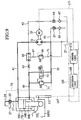
- An upper cylinder chamber 35U of the hydraulic cylinder 17R for moving the upper table 105U corresponding to the ram upward and downward is connected to the prefill valve 25 by a piping 37, and is further connected to the oil tank 27 by a piping 39.
- the upper cylinder chamber 35U mentioned above is connected to one side of a two-way piston pump 31 corresponding to a two-way fluid pump capable of rotating in two directions by a piping 41.
- a piping 43 is connected to a middle of the piping 41, and is connected to the oil tank 27 via a check valve 45 and a suction filter 47.
- the two-way piston pump 31 is rotated by the AC servo motor 33 corresponding to a servo motor.
- a piping 49 is connected to a lower cylinder chamber 35L of the hydraulic cylinder 17R, and a counter balance valve 51 and a sequence switch valve 45 corresponding to an electromagnetic poppet valve are provided in parallel.
- the counter balance valve 51 and the sequence switch valve 53 are connected to another side of the two-way piston pump 31 by a piping 55.
- a piping 61 is connected to the piping 55 in the middle thereof, and this piping 61 is connected to the oil tank 27 via a check valve 57 and a suction filter 59.
- a throttle valve 63 and a high pressure preference type shuttle valve 65 are provided between the piping 49 and the piping 41.
- a piping 67 is connected to a discharge side of the high pressure preference type shuttle valve 65.
- a relief valve 69 is connected to the piping 67, and further a piping 71 connected to the oil tank 27 is provided.
- the AC servo motor 33 rotating the two-way piston pump 31 is controlled by a control apparatus 165.
- the control apparatus 165 has a determination unit 169 for determining on the basis of a position signal 167 of the upper table 105U sent from the linear scale 111 mentioned above whether or not the bending work is finished, and an order unit 173 generating an order signal 171 for normal rotation or reverse rotation to the AC servo motor 33 on the basis of the determination of the determination unit 169.
- the two-way piston pump 31 stops and the piston 19R rapidly moves the upper table 105U downward from a state of being at a top dead center due to its own weight of the upper table 105U and the hydraulic cylinder 17R, the piping 49 and the piping 55 are communicated by switching the sequence switch valve 53, and the two-way piston pump 31 is rotated by the AC servo motor 33.
- the sequence switch valve 53 is set to a state shown in Fig. 9, and the working fluid from the lower cylinder chamber 35L is returned to the two-way piston pump 31 through the piping 49, the counter balance valve 51 and the piping 55, and is supplied to the upper cylinder chamber 35U of the hydraulic cylinder 17R from the piping 41. Accordingly, the piston 19R moves downward and the upper table 105U moves downward, thereby performing the bending work.
- the switch valve 53 is switched to a state shown in Fig. 9, the AC servo motor 33 is rotated in an opposite direction to that of the case mentioned above on the basis of a reverse rotation order from the order unit 173 so as to reverse rotate the two-way piston pump 31, and supply the working fluid from the upper cylinder chamber 35U in a state in which the piston 19R moves downward to the lower cylinder chamber 35L through the piping 41, the two-way piston pump 31, the piping 55, the switch valve 53, the piping 49 and the like. Accordingly, the piston 19R moves upward and the upper table 105U moves upward.
- the prefill valve 25 is opened according to a pilot signal 73, and the working fluid is fed to the oil tank 27 from the upper cylinder chamber 35U through the prefill valve 25.
- the present invention is not limited to the embodiments mentioned above, and can be achieved by the other aspects by suitably modifying. That is, in the embodiments mentioned above, the description is given of the press brake 101 moving the upper table 105U upward and downward, however, the absolutely same matter can be applied to a press brake moving the lower table 105L upward and downward.
Description
Claims (8)
- A press brake comprisinga frame,an upper table (5U),a lower table (5L),left and right hydraulic cylinders (17R; 17L) for moving said upper table (5U) or said lower table (5L) relatively to each other, anda plurality of hydraulic devices (21L; 21R) for controlling the hydraulic cylinders (17R; 17L), said each hydraulic device (21L; 21R) includes:characterized in thata linear scalea fluid pump, and a servo motor, whereaseach fluid pump is connected to an upper cylinder chamber (35U) and a lower cylinder chamber (35L) of its corresponding hydraulic cylinder (17R; 17L) andan oil tank (27) is provided in an upper side of each hydraulic device (21L; 21R), wherebysaid upper or lower table (5U, 5L) is moved upward and downward, andeach hydraulic device (21L) and its corresponding fluid pump is controlled independently from the other hydraulic device (21R) and its corresponding fluid pump,
said fluid pump is a two-way fluid pump, and said press brake further comprises:a crowning cylinder (13) that is provided in a center portion of the lower table (5L) so as to keep an upper end portion of the lower table (5L) straight; andanother hydraulic device for controlling the crowning cylinder (13) including a two-way fluid pump (81) and a servo motor (79). - A press brake as claimed in claim 1, wherein the respective hydraulic devices (21L;21R) connecting the respective two-way fluid pumps corresponding to the hydraulic cylinders (17L;17R) for moving the upper table (5U) or the lower table (5L) relatively each other upward and downward to the respective hydraulic cylinders (17L;17R) are provided so as to be attached to a base plate mounted to an upper portion of the respective hydraulic cylinders (17L;17R).
- The press brake according to claim 1, characterized in that said servo motor drives the respective two-way pump so as to supply a working fluid to the upper cylinder chamber (35U) or the lower cylinder chamber (35L), and that said press brake further comprises:wherein the control device comprises:a position detector detecting a vertical position of the ram; anda control device controlling the servo motor,a determination portion for determining on the basis of a signal from the position detector whether or not a bending work has been finished; andan order unit giving an order to the servo motor so as to reverse rotate the servo motor in order to reverse the two-way fluid pumps at a time of being determined by the determination unit that the bending work is finished.
- A press brake according to claim 1, characterised in that said press brake compriseswherein the first control apparatus and the second control device respectively control the first servo motor and the second servo motor in an independent manner.said upper table (5U) is a first table (5U) freely moving upward and downward;said lower table (5L) is a second table (5L) moving relative to the first table (5U) so as to approach to and separate from the first table (5U);a left hydraulic cylinder (17L) provided in a left side of the frame in order to move the first table (5U) upward and downward;a first two-way fluid pump connected to an upper cylinder chamber and a lower cylinder chamber of the left hydraulic cylinder and capable of discharging a working fluid in a normal flow direction and a reverse flow direction in order to operate the left hydraulic cylinder (17L) in a vertical direction;a first servo motor rotating the first two-way fluid pump in a normal rotation direction and a reverse rotation direction;a first control apparatus controlling the first servo motor;a right hydraulic cylinder (17R) provided in a right side of the frame in order to move the first table (5U) upward and downward;a second two-way fluid pump connected to an upper cylinder chamber and a lower cylinder chamber of the right hydraulic cylinder and capable of discharging the working fluid in the normal flow direction and the reverse flow direction in order to operate the right hydraulic cylinder (17R) in the vertical direction;a first servo motor rotating the second two-way fluid pump in the normal rotation direction and the reverse rotation direction; anda second control apparatus controlling the second servo motor,
- A press brake as claimed in claim 4, further comprising:wherein the first control apparatus is provided with a determination unit for determining on the basis of a signal from the first position detector whether or not a bending work is finished, and an order unit giving an order to the first servo motor so as to reverse rotate the first servo motor in order to reverse the first two-way fluid pump at a time of being determined by the determination unit that the bending work is finished; anda first position detector for measuring a position with respect to the second table in a left side of the first table; anda second position detector for measuring a position with respect to the second table (5L) in a right side of the first table (5U),
wherein the second control apparatus is provided with a determination unit for determining on the basis of a signal from the second position detector whether or not the bending work has been finished, and an order unit giving an order to the second servo motor so as to reverse the second servo motor for the purpose of reversing the second two-way fluid pump when it is determined by the determination unit that the bending work has been finished. - A press brake as claimed in claim 5, wherein the first two-way fluid pump is connected the left hydraulic cylinder (17L) via a first hydraulic device (21L);the second two-way fluid pump (31) is connected the right hydraulic cylinder (17R) via a second hydraulic device (21R);the first hydraulic device (21L) and the first two-way fluid pump are assembled in the left hydraulic cylinder (17L); andthe second hydraulic device (21R) and the second two-way fluid pump (31) are assembled in the right hydraulic cylinder(17R).
- A ram moving method in a press brake provided with a plurality of hydraulic cylinders (17R;17L) for moving a ram upward and downward, comprising the steps of:rotating two-way fluid pumps connected to upper cylinder chambers and lower cylinder chambers of the hydraulic cylinders each by a corresponding servo motor;supplying a working fluid to one of the upper cylinder chambers and the lower cylinder chambers in the respective hydraulic cylinders (17L;17R) so as to move the ram upward and downward;detecting a vertical position of the ram so as to determine on the basis of the detected ram position whether or not the bending work has been finished; andreversing the servo motors when it is determined that the bending work is finished, thereby reversing the two-way fluid pump so as to supply the working fluid supplied to the one cylinder chambers to another cylinder chambers and move the ram upward and downward, wherein
a crowning cylinder (13) is provided in a center portion of a lower table (5L) of the press brake, whereby said crowning cylinder (13) is controlled by a hydraulic device, which includes a two-way fluid pump (81) and a servo motor (79). - The ram moving method according to claim 7, characterized in that said method comprises the steps of:wherein the first control apparatus and the second control device respectively control the first servo motor and the second servo motor in an independent manner.rotating a first two-way fluid pump connected to an upper cylinder chamber and a lower cylinder chamber of a left hydraulic cylinder (17L) by a first servo motor;supplying a working fluid to one of the upper cylinder chamber and the lower cylinder chamber in the left hydraulic cylinder (17L) so as to move a first table (5U) close to a second table;detecting a vertical position of the first table (5U) with respect to the second table (5L) by a first position detector;determining on the basis of the detected position of the first table (5U) by a first control device whether or not a bending work is finished;supplying the working fluid supplied to the one cylinder chamber to another cylinder chamber so as to move a left portion of the first table (5U) apart from the second table (5L), in accordance that the first control apparatus reverse rotates the first servo motor so as to reverse the first two-way fluid pump, when it is determined that the bending work has been finished;rotating a second two-way fluid pump connected to an upper cylinder chamber and a lower cylinder chamber of a right hydraulic cylinder by a second servo motor;supplying the working fluid to one of the upper cylinder chamber and the lower cylinder chamber in the right hydraulic cylinder so as to move the first table (5U) close to the second table (5L);detecting the vertical position of the first table (5U) with respect to the second table (5L) by a second position detector;determining on the basis of the detected position of the first table (5U) by a second control device whether or not the bending work has been finished; andsupplying the working fluid supplied to the one cylinder chamber to another cylinder chamber so as to move a right portion of the first table (5U) apart from the second table (5L), in accordance that the second control device reverse rotates the second servo motor so as to reverse rotate the second two-way fluid pump, when it is determined that the bending work has been finished,
Applications Claiming Priority (5)
| Application Number | Priority Date | Filing Date | Title |
|---|---|---|---|
| JP29879199 | 1999-10-20 | ||
| JP29879199A JP4460090B2 (en) | 1999-10-20 | 1999-10-20 | Press brake |
| JP30251199A JP4473990B2 (en) | 1999-10-25 | 1999-10-25 | Press brake |
| JP30251199 | 1999-10-25 | ||
| PCT/JP2000/007281 WO2001028705A1 (en) | 1999-10-20 | 2000-10-19 | Press brake and ram movement method for press brake |
Publications (3)
| Publication Number | Publication Date |
|---|---|
| EP1228822A1 EP1228822A1 (en) | 2002-08-07 |
| EP1228822A4 EP1228822A4 (en) | 2003-07-02 |
| EP1228822B1 true EP1228822B1 (en) | 2005-08-17 |
Family
ID=26561658
Family Applications (1)
| Application Number | Title | Priority Date | Filing Date |
|---|---|---|---|
| EP00969901A Expired - Lifetime EP1228822B1 (en) | 1999-10-20 | 2000-10-19 | Press brake and ram movement method for press brake |
Country Status (7)
| Country | Link |
|---|---|
| US (1) | US6959581B2 (en) |
| EP (1) | EP1228822B1 (en) |
| KR (1) | KR100482728B1 (en) |
| CN (1) | CN1387466A (en) |
| DE (1) | DE60022074T2 (en) |
| TW (1) | TW503135B (en) |
| WO (1) | WO2001028705A1 (en) |
Cited By (2)
| Publication number | Priority date | Publication date | Assignee | Title |
|---|---|---|---|---|
| DE102009052531A1 (en) | 2009-11-11 | 2011-05-12 | Hoerbiger Automatisierungstechnik Holding Gmbh | machine press |
| DE102016114635A1 (en) | 2016-08-08 | 2018-02-08 | Hoerbiger Automatisierungstechnik Holding Gmbh | processing machine |
Families Citing this family (8)
| Publication number | Priority date | Publication date | Assignee | Title |
|---|---|---|---|---|
| FR2908684B1 (en) * | 2006-11-20 | 2009-11-27 | Amada Europ | MECHANICAL CONNECTION FOR FORCE TRANSFER WHILE ENSURING INSULATION |
| AT505724B1 (en) * | 2007-09-12 | 2010-06-15 | Trumpf Maschinen Austria Gmbh | DRIVE DEVICE FOR A BEND PRESS |
| FR2942980B1 (en) * | 2009-03-13 | 2011-04-08 | Amada Europ | PRESS BRAKE FOR FOLDING SHEETS |
| CN101958504A (en) * | 2010-10-21 | 2011-01-26 | 昆山德力康电子科技有限公司 | Riveter for computer connector |
| US9687896B2 (en) * | 2015-04-13 | 2017-06-27 | GrishamWorks, LLC | Sheet metal brake press |
| DE102017103091B4 (en) | 2017-02-15 | 2019-05-16 | Hoerbiger Automatisierungstechnik Holding Gmbh | machine press |
| JP6701294B2 (en) | 2018-09-19 | 2020-05-27 | 株式会社アマダ | Press brake and management system |
| CN114889194B (en) * | 2022-05-13 | 2024-01-16 | 安徽恒均粉末冶金科技股份有限公司 | Mechanical feeding mechanism for powder hydraulic press and hydraulic system thereof |
Family Cites Families (12)
| Publication number | Priority date | Publication date | Assignee | Title |
|---|---|---|---|---|
| US3677009A (en) * | 1970-11-12 | 1972-07-18 | Kelso Marine Inc | Control arrangement for the male die of a hydraulic press brake |
| FR2119528A5 (en) * | 1970-12-25 | 1972-08-04 | Amada Co Ltd | |
| DE2911901A1 (en) | 1979-03-27 | 1980-10-02 | Siempelkamp Gmbh & Co | DEVICE FOR BENDING SHEET CUTTINGS |
| US4580434A (en) * | 1983-11-14 | 1986-04-08 | Cincinnati Incorporated | Deflection compensating assembly for a press brake |
| US4797831A (en) * | 1986-11-18 | 1989-01-10 | Cincinnati Incorporated | Apparatus for synchronizing cylinder position in a multiple cylinder hydraulic press brake |
| JPH0832341B2 (en) * | 1989-08-31 | 1996-03-29 | 株式会社小松製作所 | Control device for press brake |
| FR2655907B1 (en) | 1989-12-19 | 1993-07-30 | Plazenet Jean | HYDRAULIC BENDING PRESS WITH MOBILE LOWER APRON. |
| EP0641644A1 (en) * | 1993-09-02 | 1995-03-08 | Maschinenfabrik Müller-Weingarten AG | Method for controlling the drive of a hydraulic press and apparatus for carrying out the method |
| JPH08168897A (en) | 1994-12-16 | 1996-07-02 | Nisshinbo Ind Inc | Press machine able to divisionally control die |
| JPH08281337A (en) | 1995-04-12 | 1996-10-29 | Nisshinbo Ind Inc | Method for vibration forming for press brake and press brake |
| JP3366560B2 (en) | 1996-11-08 | 2003-01-14 | 株式会社東洋工機 | Press machine |
| US6240758B1 (en) * | 1999-06-21 | 2001-06-05 | Toyokoki Co., Ltd. | Hydraulic machine |
-
2000
- 2000-10-19 DE DE60022074T patent/DE60022074T2/en not_active Expired - Lifetime
- 2000-10-19 CN CN00815237A patent/CN1387466A/en active Pending
- 2000-10-19 WO PCT/JP2000/007281 patent/WO2001028705A1/en active IP Right Grant
- 2000-10-19 EP EP00969901A patent/EP1228822B1/en not_active Expired - Lifetime
- 2000-10-19 US US10/110,210 patent/US6959581B2/en not_active Expired - Lifetime
- 2000-10-19 KR KR10-2002-7005075A patent/KR100482728B1/en active IP Right Grant
- 2000-10-20 TW TW089122032A patent/TW503135B/en not_active IP Right Cessation
Cited By (6)
| Publication number | Priority date | Publication date | Assignee | Title |
|---|---|---|---|---|
| DE102009052531A1 (en) | 2009-11-11 | 2011-05-12 | Hoerbiger Automatisierungstechnik Holding Gmbh | machine press |
| WO2011057773A2 (en) | 2009-11-11 | 2011-05-19 | Hoerbiger Automatisierungstechnik Holding Gmbh | Machine press |
| DE102016114635A1 (en) | 2016-08-08 | 2018-02-08 | Hoerbiger Automatisierungstechnik Holding Gmbh | processing machine |
| WO2018029019A1 (en) | 2016-08-08 | 2018-02-15 | Hoerbiger Automatisierungstechnik Holding Gmbh | Machine tool |
| DE102016114635B4 (en) | 2016-08-08 | 2018-09-20 | Hoerbiger Automatisierungstechnik Holding Gmbh | processing machine |
| US10837468B2 (en) | 2016-08-08 | 2020-11-17 | Hoerbiger Automatisierungstechnik Holding Gmbh | Machine tool |
Also Published As
| Publication number | Publication date |
|---|---|
| DE60022074D1 (en) | 2005-09-22 |
| US6959581B2 (en) | 2005-11-01 |
| US20050193798A1 (en) | 2005-09-08 |
| DE60022074T2 (en) | 2006-02-02 |
| KR20020044167A (en) | 2002-06-14 |
| TW503135B (en) | 2002-09-21 |
| EP1228822A4 (en) | 2003-07-02 |
| WO2001028705A1 (en) | 2001-04-26 |
| CN1387466A (en) | 2002-12-25 |
| EP1228822A1 (en) | 2002-08-07 |
| KR100482728B1 (en) | 2005-04-14 |
Similar Documents
| Publication | Publication Date | Title |
|---|---|---|
| EP1232810B1 (en) | Press brake and method of controlling bidirectional fluid pump of hydraulic cylinder of press brake | |
| EP1228822B1 (en) | Press brake and ram movement method for press brake | |
| US20040033141A1 (en) | Method and drive system for the control/regulation of linear pressure/cast movement | |
| US6370873B1 (en) | Hydraulic drive for a press | |
| US20190232353A1 (en) | Press system | |
| US9623463B2 (en) | Hydraulic press brake | |
| CN112789125B (en) | Hydraulic driving system of punching equipment | |
| EP1279488B1 (en) | Device and method for controlling stop of hydraulic press and device and method for detecting trouble of speed selector valve | |
| US20070017730A1 (en) | Hydraulic system | |
| CN109340202B (en) | Hydraulic system of large-tonnage portal frame type hydraulic press and control process thereof | |
| JP4473990B2 (en) | Press brake | |
| JP4460090B2 (en) | Press brake | |
| JPH10180500A (en) | Ram raising/lowering device | |
| KR100880244B1 (en) | High performance bending machine with reduced energy dispersion | |
| JP3681461B2 (en) | Hydraulic punch press | |
| JP4558867B2 (en) | Method of ram movement in press brake and press brake using this ram movement method | |
| JPH1128529A (en) | Method for suppressing pulsating pressure in hydraulic circuit of hydraulic cylinder and device therefor | |
| RU2710108C1 (en) | Hydraulic drive compressor | |
| JP4636646B2 (en) | Ram position control method and ram position control apparatus for press brake | |
| CN215170574U (en) | Piston type hydraulic device | |
| JP2001198623A (en) | Ram speed monitoring method in press brake and press brake using ram speed monitoring method | |
| JPH1094900A (en) | Hydraulic circuit of hydraulic cylinder | |
| JP2579369Y2 (en) | Hydraulic equipment for press machines | |
| JP3573835B2 (en) | Method and apparatus for preventing back pressure of hydraulic circuit for driving ram cylinder in hydraulic press machine | |
| JP2002263735A (en) | Press brake |
Legal Events
| Date | Code | Title | Description |
|---|---|---|---|
| PUAI | Public reference made under article 153(3) epc to a published international application that has entered the european phase |
Free format text: ORIGINAL CODE: 0009012 |
|
| 17P | Request for examination filed |
Effective date: 20020424 |
|
| AK | Designated contracting states |
Kind code of ref document: A1 Designated state(s): AT BE CH CY DE DK ES FI FR GB GR IE IT LI LU MC NL PT SE |
|
| AX | Request for extension of the european patent |
Free format text: AL;LT;LV;MK;RO;SI |
|
| A4 | Supplementary search report drawn up and despatched |
Effective date: 20030515 |
|
| RBV | Designated contracting states (corrected) |
Designated state(s): AT BE CH CY DE FI FR GB IT LI |
|
| 17Q | First examination report despatched |
Effective date: 20040415 |
|
| GRAP | Despatch of communication of intention to grant a patent |
Free format text: ORIGINAL CODE: EPIDOSNIGR1 |
|
| RBV | Designated contracting states (corrected) |
Designated state(s): DE FI FR GB IT |
|
| RIN1 | Information on inventor provided before grant (corrected) |
Inventor name: KANNO, KAZUHIRO,AMADA ENGINEERING CENTER CO.,LTD. |
|
| GRAS | Grant fee paid |
Free format text: ORIGINAL CODE: EPIDOSNIGR3 |
|
| GRAA | (expected) grant |
Free format text: ORIGINAL CODE: 0009210 |
|
| AK | Designated contracting states |
Kind code of ref document: B1 Designated state(s): DE FI FR GB IT |
|
| REG | Reference to a national code |
Ref country code: GB Ref legal event code: FG4D |
|
| REF | Corresponds to: |
Ref document number: 60022074 Country of ref document: DE Date of ref document: 20050922 Kind code of ref document: P |
|
| ET | Fr: translation filed | ||
| PLBE | No opposition filed within time limit |
Free format text: ORIGINAL CODE: 0009261 |
|
| STAA | Information on the status of an ep patent application or granted ep patent |
Free format text: STATUS: NO OPPOSITION FILED WITHIN TIME LIMIT |
|
| 26N | No opposition filed |
Effective date: 20060518 |
|
| REG | Reference to a national code |
Ref country code: FR Ref legal event code: PLFP Year of fee payment: 16 |
|
| REG | Reference to a national code |
Ref country code: FR Ref legal event code: PLFP Year of fee payment: 17 |
|
| PGFP | Annual fee paid to national office [announced via postgrant information from national office to epo] |
Ref country code: FI Payment date: 20161012 Year of fee payment: 17 |
|
| REG | Reference to a national code |
Ref country code: FR Ref legal event code: PLFP Year of fee payment: 18 |
|
| PG25 | Lapsed in a contracting state [announced via postgrant information from national office to epo] |
Ref country code: FI Free format text: LAPSE BECAUSE OF NON-PAYMENT OF DUE FEES Effective date: 20171019 |
|
| REG | Reference to a national code |
Ref country code: FR Ref legal event code: PLFP Year of fee payment: 19 |
|
| PGFP | Annual fee paid to national office [announced via postgrant information from national office to epo] |
Ref country code: DE Payment date: 20191021 Year of fee payment: 20 |
|
| PGFP | Annual fee paid to national office [announced via postgrant information from national office to epo] |
Ref country code: IT Payment date: 20191028 Year of fee payment: 20 Ref country code: FR Payment date: 20191028 Year of fee payment: 20 |
|
| PGFP | Annual fee paid to national office [announced via postgrant information from national office to epo] |
Ref country code: GB Payment date: 20191021 Year of fee payment: 20 |
|
| REG | Reference to a national code |
Ref country code: DE Ref legal event code: R071 Ref document number: 60022074 Country of ref document: DE |
|
| REG | Reference to a national code |
Ref country code: GB Ref legal event code: PE20 Expiry date: 20201018 |
|
| PG25 | Lapsed in a contracting state [announced via postgrant information from national office to epo] |
Ref country code: GB Free format text: LAPSE BECAUSE OF EXPIRATION OF PROTECTION Effective date: 20201018 |