EP1228740A1 - Laser eye treatment apparatus - Google Patents
Laser eye treatment apparatus Download PDFInfo
- Publication number
- EP1228740A1 EP1228740A1 EP02002286A EP02002286A EP1228740A1 EP 1228740 A1 EP1228740 A1 EP 1228740A1 EP 02002286 A EP02002286 A EP 02002286A EP 02002286 A EP02002286 A EP 02002286A EP 1228740 A1 EP1228740 A1 EP 1228740A1
- Authority
- EP
- European Patent Office
- Prior art keywords
- treatment
- mirror
- laser
- irradiation
- optical system
- Prior art date
- Legal status (The legal status is an assumption and is not a legal conclusion. Google has not performed a legal analysis and makes no representation as to the accuracy of the status listed.)
- Granted
Links
- 238000011282 treatment Methods 0.000 title claims abstract description 121
- 230000003287 optical effect Effects 0.000 claims abstract description 52
- 238000013532 laser treatment Methods 0.000 claims abstract description 29
- 238000001514 detection method Methods 0.000 claims abstract description 27
- 230000001678 irradiating effect Effects 0.000 claims abstract description 20
- 230000008859 change Effects 0.000 claims abstract description 8
- 230000007246 mechanism Effects 0.000 claims description 12
- 238000005286 illumination Methods 0.000 description 6
- 230000000649 photocoagulation Effects 0.000 description 6
- 230000015271 coagulation Effects 0.000 description 3
- 238000005345 coagulation Methods 0.000 description 3
- 238000006073 displacement reaction Methods 0.000 description 3
- 238000010586 diagram Methods 0.000 description 2
- 230000004048 modification Effects 0.000 description 2
- 238000012986 modification Methods 0.000 description 2
- 239000013307 optical fiber Substances 0.000 description 2
- 230000002093 peripheral effect Effects 0.000 description 2
- 230000004044 response Effects 0.000 description 2
- 230000002159 abnormal effect Effects 0.000 description 1
- 239000012141 concentrate Substances 0.000 description 1
- 230000000694 effects Effects 0.000 description 1
- 239000000835 fiber Substances 0.000 description 1
- 238000000034 method Methods 0.000 description 1
- 230000008569 process Effects 0.000 description 1
- 230000001681 protective effect Effects 0.000 description 1
- 230000000007 visual effect Effects 0.000 description 1
Images




Classifications
-
- A—HUMAN NECESSITIES
- A61—MEDICAL OR VETERINARY SCIENCE; HYGIENE
- A61F—FILTERS IMPLANTABLE INTO BLOOD VESSELS; PROSTHESES; DEVICES PROVIDING PATENCY TO, OR PREVENTING COLLAPSING OF, TUBULAR STRUCTURES OF THE BODY, e.g. STENTS; ORTHOPAEDIC, NURSING OR CONTRACEPTIVE DEVICES; FOMENTATION; TREATMENT OR PROTECTION OF EYES OR EARS; BANDAGES, DRESSINGS OR ABSORBENT PADS; FIRST-AID KITS
- A61F9/00—Methods or devices for treatment of the eyes; Devices for putting in contact-lenses; Devices to correct squinting; Apparatus to guide the blind; Protective devices for the eyes, carried on the body or in the hand
- A61F9/007—Methods or devices for eye surgery
- A61F9/008—Methods or devices for eye surgery using laser
- A61F9/00821—Methods or devices for eye surgery using laser for coagulation
-
- A—HUMAN NECESSITIES
- A61—MEDICAL OR VETERINARY SCIENCE; HYGIENE
- A61F—FILTERS IMPLANTABLE INTO BLOOD VESSELS; PROSTHESES; DEVICES PROVIDING PATENCY TO, OR PREVENTING COLLAPSING OF, TUBULAR STRUCTURES OF THE BODY, e.g. STENTS; ORTHOPAEDIC, NURSING OR CONTRACEPTIVE DEVICES; FOMENTATION; TREATMENT OR PROTECTION OF EYES OR EARS; BANDAGES, DRESSINGS OR ABSORBENT PADS; FIRST-AID KITS
- A61F9/00—Methods or devices for treatment of the eyes; Devices for putting in contact-lenses; Devices to correct squinting; Apparatus to guide the blind; Protective devices for the eyes, carried on the body or in the hand
- A61F9/007—Methods or devices for eye surgery
- A61F9/008—Methods or devices for eye surgery using laser
-
- A—HUMAN NECESSITIES
- A61—MEDICAL OR VETERINARY SCIENCE; HYGIENE
- A61B—DIAGNOSIS; SURGERY; IDENTIFICATION
- A61B17/00—Surgical instruments, devices or methods
- A61B2017/00017—Electrical control of surgical instruments
-
- A—HUMAN NECESSITIES
- A61—MEDICAL OR VETERINARY SCIENCE; HYGIENE
- A61B—DIAGNOSIS; SURGERY; IDENTIFICATION
- A61B17/00—Surgical instruments, devices or methods
- A61B2017/00017—Electrical control of surgical instruments
- A61B2017/00137—Details of operation mode
- A61B2017/00154—Details of operation mode pulsed
- A61B2017/00181—Means for setting or varying the pulse energy
-
- A—HUMAN NECESSITIES
- A61—MEDICAL OR VETERINARY SCIENCE; HYGIENE
- A61F—FILTERS IMPLANTABLE INTO BLOOD VESSELS; PROSTHESES; DEVICES PROVIDING PATENCY TO, OR PREVENTING COLLAPSING OF, TUBULAR STRUCTURES OF THE BODY, e.g. STENTS; ORTHOPAEDIC, NURSING OR CONTRACEPTIVE DEVICES; FOMENTATION; TREATMENT OR PROTECTION OF EYES OR EARS; BANDAGES, DRESSINGS OR ABSORBENT PADS; FIRST-AID KITS
- A61F9/00—Methods or devices for treatment of the eyes; Devices for putting in contact-lenses; Devices to correct squinting; Apparatus to guide the blind; Protective devices for the eyes, carried on the body or in the hand
- A61F9/007—Methods or devices for eye surgery
- A61F9/008—Methods or devices for eye surgery using laser
- A61F2009/00861—Methods or devices for eye surgery using laser adapted for treatment at a particular location
- A61F2009/00863—Retina
Definitions
- the present invention relates to a laser treatment apparatus used for performing treatment on a treatment part (an affected part) of a patient's eye by irradiating the treatment part with a laser beam for treatment.
- Many laser treatment apparatuses for use in a photocoagulation treatment or the like have a manipulator for moving a reflection mirror which reflects a laser beam for treatment toward a part to be treated (an affected part) of a patient's eye, i.e., for changing an inclination angle of the reflection mirror.
- the manipulator is provided in order to allow fine adjustment during alignment of an irradiation point of the treatment laser beam to the treatment part.
- a repeat function of periodically irradiating a treatment laser beam while a trigger switch is being pressed is frequently used. This repeat function can be combined with movement (change) of an irradiation point by the manipulator, thereby successively treating a wide area.
- the present invention has been made in view of the above circumstances and has an object to overcome the above problems and to provide a laser treatment apparatus capable of appropriately performing laser irradiation to allow a satisfactory treatment.
- a laser treatment apparatus used for performing treatment on a treatment part of a patient's eye by irradiating the treatment part with a laser beam for treatment, characterized by including: a treatment beam irradiation optical system for irradiating the treatment beam, the system including a mirror which reflects the treatment beam toward the treatment part; mirror moving means for moving the mirror to change a point to be irradiated by the treatment beam; and detection means for detecting motion of the mirror.
- the laser treatment apparatus further includes control means for controlling irradiation of the treatment beam based on detection results by the detection means.
- the laser treatment apparatus further includes irradiation command signal input means for inputting a command signal to perform the irradiation of the treatment beam, wherein the control means stops the irradiation of the treatment beam when the detection means detects that the mirror is moving while the irradiation command signal is input.
- the laser treatment apparatus further includes selection means for selecting a repeat mode in which, during the input of the irradiation command signal, the treatment beam is repeatedly irradiated according to a preset time interval, wherein when the repeat mode is selected, the control means controls the irradiation of the treatment beam based on the detection results by the detection means and at the time interval.
- the mirror moving means includes an operation member which is operated by an operator to move the mirror
- the detection means includes a sensor for detecting motion of the mirror.
- the mirror moving means includes driving command signal input means whereby an operator inputs a driving command signal to move the mirror, and the detection means detects the presence/absence of input of the driving command signal.
- the laser treatment apparatus further includes an aiming beam irradiation optical system, having an optical axis in a predetermined relation to an optical axis of the treatment beam irradiation optical system, for irradiating an aiming beam by reflecting the aiming beam toward the treatment part by the mirror of the treatment beam irradiation optical system, wherein the detection means includes image pickup means for picking up an image of the treatment part and detects motion of the mirror by processing the picked-up image to detect shifting of a point to be irradiated by the aiming beam.
- an aiming beam irradiation optical system having an optical axis in a predetermined relation to an optical axis of the treatment beam irradiation optical system, for irradiating an aiming beam by reflecting the aiming beam toward the treatment part by the mirror of the treatment beam irradiation optical system
- the detection means includes image pickup means for picking up an image of the treatment part and detects motion of the mirror by processing the picked-up image to detect shifting of a point to be
- a laser treatment apparatus used for performing treatment on a treatment part of a patient's eye by irradiating the treatment part with a laser beam for treatment, characterized by including: a treatment beam irradiation optical system including a mirror which reflects the treatment beam toward the treatment part; a mirror moving mechanism for changing an inclination angle or an arrangement position of the mirror, the moving mechanism including an operation lever; and a sensor for detecting motion of the operation lever.
- the laser treatment apparatus further includes a controller for controlling irradiation of the treatment beam based on detection results by the sensor.
- a laser treatment apparatus used for performing treatment on a treatment part of a patient's eye by irradiating the treatment part with a laser beam for treatment, characterized by including: a treatment beam irradiation optical system for irradiating the treatment beam, the system including a mirror which reflects the treatment beam toward the treatment part; an aiming beam irradiation optical system, having an optical axis in a predetermined relation to an optical axis of the treatment beam irradiation optical system, for irradiating an aiming beam by reflecting the aiming beam toward the treatment part by the mirror of the treatment beam irradiation optical system; a mirror moving mechanism for changing an inclination angle or an arrangement position of the mirror; an image pickup device for picking up an image of the treatment part; and a detection unit for detecting motion of the mirror by processing the picked-up image to detect shifting of a point to be irradiated by the aiming beam.
- the laser treatment apparatus further includes a controller for controlling irradiation of the treatment beam based on detection results by the detection unit.
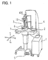
- Fig. 1 is a perspective view of the laser treatment apparatus in the present embodiment.
- Fig. 2 is a schematic structural view of an optical system of the apparatus. It is to be noted that directions with respect to the apparatus seen from an operator side are defined as follows: a leftward direction is an X1 direction; a rightward direction is an X2 direction; an upward direction is a Y1 direction; a downward direction is a Y2 direction; a forward direction is Z1 direction; and a backward direction is a Z2 direction.
- Numeral 1 is a main unit of the laser treatment apparatus, which is internally provided with a laser source 70 which emits a laser beam for treatment (hereafter, simply referred to as a treatment beam), a laser source 78 which emits a laser beam for aiming (hereafter, simply referred to as an aiming beam), and other elements.
- Numeral 2 is a control unit used for inputting and setting laser irradiation conditions (i.e., irradiation conditions of the treatment beam), output power of the aiming beam, and other conditions.
- Numeral 3 is a slit lamp delivery provided with an illumination optical system 50 and an observation optical system 60. An irradiation unit 400 is attached to the slit lamp delivery 3.
- This unit 400 is internally provided with an irradiation optical system 40 for performing laser irradiation (irradiation of the treatment beam) to a patient's eye E.
- Numeral 5 is a foot switch for generating a laser irradiation command signal (a trigger signal).
- Numeral 6 is a joystick for moving the slit lamp delivery 3 on a stand table 7.
- Numeral 71 is a beam splitter which transmits a large part of the treatment beam and reflects a part of the same.
- the treatment beam reflected by the beam splitter 71 is made incident to an output sensor 73 via a diffusing plate 72.
- the output sensor 73 detects the output power of the treatment beam emitted from the laser source 70.
- Numeral 74 is a first safety shutter. This shutter 74 is moved out from the optical path by operation of a shutter driving device 91 (see Fig. 4) when the foot switch 5 is pressed to generate the command signal to perform laser irradiation, thus allowing the treatment beam to pass along the optical path. In case of occurrence of abnormal events, the shutter 74 is moved in the optical path to intercept the treatment beam. The opening and closing of the first safety shutter 74 is detected by a shutter sensor 74a.
- the aiming beam emitted from the laser source (a laser diode in the present embodiment) 78 passes through a collimator lens 79 and is made coaxial with the treatment beam by a dichroic mirror 80.
- Numeral 81 is a second safety shutter. The opening and closing of this shutter 81 by a shutter driving device 92 (see Fig. 4) is detected by a shutter sensor 81a.
- Numeral 82 is a light condensing lens 82 which concentrates each laser beam (the treatment beam and the aiming beam) to an entrance face 4a of an optical fiber 4 . Each laser beam is guided through the optical fiber 4 to the irradiation unit 400.
- Each laser beam delivered into the irradiation unit 400 passes through a relay lens 41, zoom lenses 42 movable in the optical axis L to change a spot size, and an objective lens 43.
- Each laser beam is then reflected by a reflection mirror 19 toward the eye E to irradiate a treatment part (an affected part) of the eye E through a contact lens 44.
- Numeral 50 is an illumination optical system for projecting a slit light to the eye E.
- This illumination optical system 50 is constructed of an illumination light source, a condenser lens, a slit plate, a projection lens, and others.
- Numeral 60 is an observation optical system constructed of an objective lens, a variable magnification optical system, a protective filter, an erect prism group, a field diaphragm, an eyepiece lens, and others.
- a manipulator 10 for moving the reflection mirror 19 to finely adjust a point to be irradiated (an irradiation point) by each laser beam delivered through the fiber cable 4,
- the mirror 19 is swung by operation of the manipulator 10. In other words, an inclination angle of the mirror 19 is changed. Alternatively, an arrangement position of the mirror 19 may be changed.
- the manipulator 10 is provided with an operation lever 11 (see Fig. 3) extending backward (in the Z2 direction) of the slit lamp delivery 3.
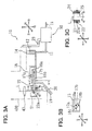
- Fig. 3A is an explanatory view of the mechanism of the manipulator 10 seen from the side of the apparatus.
- Fig. 3B is a sectional view taken on line A-A in Fig. 3A.
- Fig. 3C is a sectional view taken on line C-C in Fig. 3A.
- annular rotation member 21 is held to be rotatable about the optical axis L of the objective lens 43 in directions indicated by arrows R1 and R2.
- Each laser beam passing through the objective lens 43 is allowed to pass through the interior of the rotation member 21.
- the rotation member 21 is rotatably fit on a pipe 24 via a gear 25.
- the pipe 24 is fixed to the lower end part of the irradiation unit 400. Thus, each laser beam passes through the interior of the pipe 24.
- a support member 22 extending backward (in the Z2 direction) is mounted on the peripheral surface of the rotation member 21 with a screw 22a so that the support member 22 is turnable about the screw 22a as a supporting point in directions indicated by arrows R3 and R4.
- a mirror holding base 20 which fixedly holds the reflection mirror 19 is fixed to the support member 22. Accordingly, the reflection mirror 19 is allowed to swing about the optical axis L in the R1 and R2 directions and to swing about the screw 22a in the R3 and R4 directions. This makes it possible to change an inclination angle of the mirror 19 to change a direction that reflects each laser beam.
- the operation lever 11 used for swinging the mirror 19 is provided with a manipulator sensor part 30 for detecting the swing of the mirror 19.
- the detailed mechanism of the sensor part 30 will be explained later.
- the lever 11 is partially inserted in a cylindrical member 31 (see Fig. 5) of the sensor part 30 and the cylindrical member 31 is fixed to an arm 23 attached to a rear end of a case configuring the irradiation unit 400.
- the upper bent portion of the lever 11 is joined to an elastic rubber rod 12 attached to a fixing member 14.
- This rubber rod 12 is formed with notches on its peripheral surface and in a perpendicular direction to the center axis of the rod, so that the rod 12 can be flexibly bent in the perpendicular direction to the center axis.
- the fixing member 14 is attached to the inner wall of the case configuring the irradiation unit 400.
- the joint portion between the lever 11 and the rubber rod 12 functions as a fulcrum of the principle of leverage with respect to the lever 11. It is to be noted that the lever 11 and the arm 23 are actually curved extending from the irradiation unit 400 in order to prevent interference with the case configuring the slit lamp delivery 3. In Fig. 3A, however, the lever 11 and the arm 23 are schematically shown.
- An operation transmitting holder 16 is fixed to the lever 11.
- the holder 16 is provided with a pin 17a extending downward (in the Y2 direction) from an upper wall of the holder 16 and a pin 17b extending leftward (in the X1 direction) from a side wall as shown in Figs. 3A and 3B.
- the pins 18a-18c are fixed to the mirror holding base 20 such that the pins 18a and 18c extending in parallel and backward (in the Z2 direction) from the mirror holding base 20 engage with the pin 17a sandwiched therebetween and the pins 18a and 18b extending in parallel and backward (in the Z2 direction) from the mirror holding base 20 engage with the pin 17b sandwiched therebetween.
- the mechanism of the manipulator 10 is configured such that, when the lever 11 is in the center position (reference position) of the cylindrical member 31, each laser beam reflected by the mirror 19 is irradiated to the center of the observation visual field provided by the observation optical system 60.
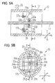
- Fig. 5A is a sectional view of the sensor part 30, showing the internal mechanism thereof.
- Fig. 5B is a sectional view taken on line B-B in Fig. 5A.
- Fig. 5A is a sectional view taken on line D-D in Fig. 5B.
- shafts 32a and 32b are disposed to sandwich the lever 11 from above and below, and shafts 33a and 33b are disposed to sandwich the lever 11 from right and left. Both ends of each of the shafts 32a and 32b are fixed to bases 34a and 34b which are linearly movable on rails 36a and 36b fixedly disposed vertically extending in the cylindrical member 31.
- An electrically conductive brush 38 is attached to the base 34b and in contact with a resistance surface of a linear potentiometer 39 fixedly provided in the cylindrical member 31. Based on resistance values of the linear potentiometer 39, the displacement of the base 34b, namely, the vertical displacement of the lever 11 can be detected.
- each of the shafts 33a and 33b are fixed to bases 35a and 35b which are linearly movable on rails 37a and 37b fixedly disposed horizontally extending in the cylindrical member 31.
- An electrically conductive brush 25 is attached to the base 35b and in contact with a resistance surface of a linear potentiometer 26 fixedly provided in the cylindrical member 31. Based on resistance values of the linear potentiometer 26, the lateral displacement of the lever 11 can be detected.
- the repeat mode For execution of the treatment such as panretinal photocoagulation in which the laser irradiation is performed a large number of times, it is preferable to use the repeat mode of repeatedly irradiating the treatment beam at fixed intervals while the laser irradiation command signal is being input from the foot switch 5.
- This repeat mode is selected by the switch 2a on the control unit 2. If the repeat mode is not selected, the apparatus goes into a single mode of irradiating the treatment beam only once in response to the laser irradiation command signal from the foot switch 5.
- an interval switch 2b is used to set a time interval for irradiation. For example, if a period of the time interval is set to one second, the treatment beam is irradiated at intervals of one second.
- a coagulation time, output power, and other laser irradiation conditions are set with unillustrated switches provided on the control unit 2.
- the operator observes an eye fundus Ef of the eye E through the observation optical system 60, the eye E being illuminated by the illumination light from the illumination optical system 50.
- An unillustrated aiming switch is operated to emit the aiming beam. While observing the aiming beam irradiated to the eye fundus Ef, the operator manipulates the joystick 6 and the operation lever 11 of the manipulator 10 to make positional alignment with respect to the treatment part on the eye fundus Ef.
- a control part 90 controls the laser source 70 to perform the laser irradiation at intervals of the period previously set with use of the interval switch 2b.
- the control part 90 controls the shutter driving device 91 to open and close the first safety shutter 74 at the preset time intervals,
- the operator operates the lever 11 according to the time intervals, sequentially moving (changing) an irradiation point on the eye fundus Ef.
- This motion of the lever 11 is detected by the sensor part 30.
- the control part 90 determines whether or not the lever 11 is in motion, or whether or not the mirror 19 is swinging. To be more specific, this determination is made based on for example the amount of change per unit time in resistance values detected by the linear potentiometers 26 and 39.
- Ti represents the preset interval period for an interval signal Si.
- the control part 90 controls to perform the laser irradiation in the same timing with the period Ti of the interval signal Si (see Laser irradiation signal Sr in Fig. 6).
- the operating signal Sm from the sensor part 30 remains input even when the next interval signal Si comes in, in other words, the next interval period comes during operation of the lever 11.
- the first safety shutter 74 is held closed to maintain the interception of the treatment beam.
- the first safety shutter 74 is released to enable the laser irradiation. Thereafter, the execution time of this laser irradiation is defined as a restart time and the interval signal Si is then generated at intervals of the period Ti. It is to be noted that stop/release of the laser irradiation may be performed by control of actuation of the laser source 70 itself.
- the laser irradiation timing is controlled by the control part 90, so that execution of the laser irradiation is prevented while the mirror 19 is swinging.
- This can prevent a photocoagulation spot from shifting or deviating in a direction corresponding to a mirror moving direction, thus enabling the laser irradiation at uniform irradiation density.
- the repeat mode is selected.
- the laser irradiation is stopped when the swinging of the reflection mirror 19 is detected and the laser irradiation is performed in response to the laser irradiation command signal from the foot switch 5 at the time when the swinging of the mirror 19 is not detected.
- the above embodiment is the example of mechanically moving the mirror 19.
- the mirror 19 may be arranged to be electrically swung by a motor or the like.
- the presence/absence of input signal related to the operation lever or an operation switch for swinging the mirror 19 is used to detect whether the mirror 19 is in motion or not.
- the mirror 19 may be driven by two or more step motors.
- an operation signal of the lever 11 is input in the form of signals of the potentiometers 26 and 39 to the control part 90.
- the real moving distance of each laser beam is very small. To make it easy to operate the lever 11, therefore, their ratio is set so that the operation amount of the lever 11 is a proportionally amplified amount of the real moving amount of each laser beam. If the mirror 19 is driven by two or more step motors, this ratio may be determined at operator's choice.
- Fig. 7 is a structural view of another embodiment of the invention. In this figure, like elements to those in the above embodiment are given like numerals.
- a half mirror 65 is disposed in the optical path of the observation optical system 60.
- a CCD camera 66 is placed in a direction that the half mirror 65 reflects light.
- An image signal output from the CCD camera 66 is input to an image processing part 67 in the main unit 1.
- the image processing part 67 is connected to the control part 90.
- the aiming beam irradiated to the eye fundus Ef is observed through the observation optical system 60 and image-picked up, or photographed by the CCD camera 66.
- the image processing part 67 processes the image signal output from the CCD camera 66 to detect the position of the aiming beam.
- the control part 90 determines that the mirror 19 is swinging, At this time, the first shutter 74 is moved in the optical path of the treatment beam to interrupt the laser irradiation during movement of the reflection mirror 19.
- the laser irradiation can be appropriately performed for allowing satisfactory photocoagulation or other treatments.
Landscapes
- Health & Medical Sciences (AREA)
- Ophthalmology & Optometry (AREA)
- Heart & Thoracic Surgery (AREA)
- Vascular Medicine (AREA)
- Optics & Photonics (AREA)
- Surgery (AREA)
- Engineering & Computer Science (AREA)
- Biomedical Technology (AREA)
- Physics & Mathematics (AREA)
- Nuclear Medicine, Radiotherapy & Molecular Imaging (AREA)
- Life Sciences & Earth Sciences (AREA)
- Animal Behavior & Ethology (AREA)
- General Health & Medical Sciences (AREA)
- Public Health (AREA)
- Veterinary Medicine (AREA)
- Laser Surgery Devices (AREA)
- Radiation-Therapy Devices (AREA)
Abstract
Description
- The present invention relates to a laser treatment apparatus used for performing treatment on a treatment part (an affected part) of a patient's eye by irradiating the treatment part with a laser beam for treatment.
- Many laser treatment apparatuses for use in a photocoagulation treatment or the like have a manipulator for moving a reflection mirror which reflects a laser beam for treatment toward a part to be treated (an affected part) of a patient's eye, i.e., for changing an inclination angle of the reflection mirror. The manipulator is provided in order to allow fine adjustment during alignment of an irradiation point of the treatment laser beam to the treatment part. In a treatment such as panretinal photocoagulation in which the treatment laser beam is irradiated a large number of times to form many photocoagulation spots, a repeat function of periodically irradiating a treatment laser beam while a trigger switch is being pressed is frequently used. This repeat function can be combined with movement (change) of an irradiation point by the manipulator, thereby successively treating a wide area.
- However, if laser irradiation is performed during movement of the reflection mirror due to for example the operation of the manipulator at erroneous timings, coagulation spots would be formed in nonuniform shapes and at uneven coagulation density. Consequently, the laser irradiation could not be appropriately executed.
- The present invention has been made in view of the above circumstances and has an object to overcome the above problems and to provide a laser treatment apparatus capable of appropriately performing laser irradiation to allow a satisfactory treatment.
- Additional objects and advantages of the invention will be set forth in part in the description which follows and in part will be obvious from the description, or may be learned by practice of the invention. The objects and advantages of the invention may be realized and attained by means of the instrumentalities and combinations particularly pointed out in the appended claims.
- To achieve the purpose of the invention, there is provided a laser treatment apparatus used for performing treatment on a treatment part of a patient's eye by irradiating the treatment part with a laser beam for treatment, characterized by including: a treatment beam irradiation optical system for irradiating the treatment beam, the system including a mirror which reflects the treatment beam toward the treatment part; mirror moving means for moving the mirror to change a point to be irradiated by the treatment beam; and detection means for detecting motion of the mirror.
- Preferably, the laser treatment apparatus further includes control means for controlling irradiation of the treatment beam based on detection results by the detection means.
- More preferably, the laser treatment apparatus further includes irradiation command signal input means for inputting a command signal to perform the irradiation of the treatment beam, wherein the control means stops the irradiation of the treatment beam when the detection means detects that the mirror is moving while the irradiation command signal is input.
- Preferably, the laser treatment apparatus further includes selection means for selecting a repeat mode in which, during the input of the irradiation command signal, the treatment beam is repeatedly irradiated according to a preset time interval, wherein when the repeat mode is selected, the control means controls the irradiation of the treatment beam based on the detection results by the detection means and at the time interval.
- In the laser treatment apparatus, preferably, the mirror moving means includes an operation member which is operated by an operator to move the mirror, and the detection means includes a sensor for detecting motion of the mirror.
- It is preferable that the mirror moving means includes driving command signal input means whereby an operator inputs a driving command signal to move the mirror, and the detection means detects the presence/absence of input of the driving command signal.
- Preferably, the laser treatment apparatus further includes an aiming beam irradiation optical system, having an optical axis in a predetermined relation to an optical axis of the treatment beam irradiation optical system, for irradiating an aiming beam by reflecting the aiming beam toward the treatment part by the mirror of the treatment beam irradiation optical system, wherein the detection means includes image pickup means for picking up an image of the treatment part and detects motion of the mirror by processing the picked-up image to detect shifting of a point to be irradiated by the aiming beam.
- According to another aspect of the present invention, there is provide a laser treatment apparatus used for performing treatment on a treatment part of a patient's eye by irradiating the treatment part with a laser beam for treatment, characterized by including: a treatment beam irradiation optical system including a mirror which reflects the treatment beam toward the treatment part; a mirror moving mechanism for changing an inclination angle or an arrangement position of the mirror, the moving mechanism including an operation lever; and a sensor for detecting motion of the operation lever.
- Preferably, the laser treatment apparatus further includes a controller for controlling irradiation of the treatment beam based on detection results by the sensor.
- Furthermore, according to another aspect of the present invention, there is provided a laser treatment apparatus used for performing treatment on a treatment part of a patient's eye by irradiating the treatment part with a laser beam for treatment, characterized by including: a treatment beam irradiation optical system for irradiating the treatment beam, the system including a mirror which reflects the treatment beam toward the treatment part; an aiming beam irradiation optical system, having an optical axis in a predetermined relation to an optical axis of the treatment beam irradiation optical system, for irradiating an aiming beam by reflecting the aiming beam toward the treatment part by the mirror of the treatment beam irradiation optical system; a mirror moving mechanism for changing an inclination angle or an arrangement position of the mirror; an image pickup device for picking up an image of the treatment part; and a detection unit for detecting motion of the mirror by processing the picked-up image to detect shifting of a point to be irradiated by the aiming beam.
- Preferably, the laser treatment apparatus further includes a controller for controlling irradiation of the treatment beam based on detection results by the detection unit.
- The accompanying drawings, which are incorporated in and constitute a part of this specification illustrate an embodiment of the invention and, together with the description, serve to explain the objects, advantages and principles of the invention.
- In the drawings,
- Fig. 1 is a perspective view of a laser treatment apparatus in an embodiment according to the present invention;
- Fig. 2 is a structural view of an optical system of the apparatus;
- Figs. 3A to 3C are explanatory view showing a driving mechanism of a manipulator in the apparatus;
- Fig. 4 is a block diagram of a control system of the apparatus;
- Fig. 5 is an explanatory view showing a mechanism of a manipulator sensor part;
- Fig. 6 is an explanatory view showing manipulator operating signals and laser irradiation timings; and
- Fig. 7 is a view showing an optical system of an apparatus in a modified example according to the present invention.
-
- A detailed description of a preferred embodiment of a laser treatment apparatus embodying the present invention will now be given referring to the accompanying drawings. Fig. 1 is a perspective view of the laser treatment apparatus in the present embodiment. Fig. 2 is a schematic structural view of an optical system of the apparatus. It is to be noted that directions with respect to the apparatus seen from an operator side are defined as follows: a leftward direction is an X1 direction; a rightward direction is an X2 direction; an upward direction is a Y1 direction; a downward direction is a Y2 direction; a forward direction is Z1 direction; and a backward direction is a Z2 direction.
- Numeral 1 is a main unit of the laser treatment apparatus, which is internally provided with a
laser source 70 which emits a laser beam for treatment (hereafter, simply referred to as a treatment beam), alaser source 78 which emits a laser beam for aiming (hereafter, simply referred to as an aiming beam), and other elements.Numeral 2 is a control unit used for inputting and setting laser irradiation conditions (i.e., irradiation conditions of the treatment beam), output power of the aiming beam, and other conditions. Numeral 3 is a slit lamp delivery provided with an illuminationoptical system 50 and an observationoptical system 60. Anirradiation unit 400 is attached to theslit lamp delivery 3. Thisunit 400 is internally provided with an irradiationoptical system 40 for performing laser irradiation (irradiation of the treatment beam) to a patient's eye E. Numeral 5 is a foot switch for generating a laser irradiation command signal (a trigger signal). Numeral 6 is a joystick for moving theslit lamp delivery 3 on a stand table 7. - Numeral 71 is a beam splitter which transmits a large part of the treatment beam and reflects a part of the same. The treatment beam reflected by the beam splitter 71 is made incident to an
output sensor 73 via adiffusing plate 72. Theoutput sensor 73 detects the output power of the treatment beam emitted from thelaser source 70. - Numeral 74 is a first safety shutter. This
shutter 74 is moved out from the optical path by operation of a shutter driving device 91 (see Fig. 4) when thefoot switch 5 is pressed to generate the command signal to perform laser irradiation, thus allowing the treatment beam to pass along the optical path. In case of occurrence of abnormal events, theshutter 74 is moved in the optical path to intercept the treatment beam. The opening and closing of thefirst safety shutter 74 is detected by ashutter sensor 74a. - The aiming beam emitted from the laser source (a laser diode in the present embodiment) 78 passes through a
collimator lens 79 and is made coaxial with the treatment beam by adichroic mirror 80. Numeral 81 is a second safety shutter. The opening and closing of thisshutter 81 by a shutter driving device 92 (see Fig. 4) is detected by ashutter sensor 81a. Numeral 82 is alight condensing lens 82 which concentrates each laser beam (the treatment beam and the aiming beam) to anentrance face 4a of an optical fiber 4 . Each laser beam is guided through the optical fiber 4 to theirradiation unit 400. - Each laser beam delivered into the
irradiation unit 400 passes through arelay lens 41,zoom lenses 42 movable in the optical axis L to change a spot size, and anobjective lens 43. Each laser beam is then reflected by areflection mirror 19 toward the eye E to irradiate a treatment part (an affected part) of the eye E through acontact lens 44. Numeral 50 is an illumination optical system for projecting a slit light to the eye E. This illuminationoptical system 50 is constructed of an illumination light source, a condenser lens, a slit plate, a projection lens, and others. Numeral 60 is an observation optical system constructed of an objective lens, a variable magnification optical system, a protective filter, an erect prism group, a field diaphragm, an eyepiece lens, and others. - In the
irradiation unit 400, there is provided amanipulator 10 for moving thereflection mirror 19 to finely adjust a point to be irradiated (an irradiation point) by each laser beam delivered through the fiber cable 4, In the present embodiment, themirror 19 is swung by operation of themanipulator 10. In other words, an inclination angle of themirror 19 is changed. Alternatively, an arrangement position of themirror 19 may be changed. Themanipulator 10 is provided with an operation lever 11 (see Fig. 3) extending backward (in the Z2 direction) of theslit lamp delivery 3. - Fig. 3A is an explanatory view of the mechanism of the
manipulator 10 seen from the side of the apparatus. Fig. 3B is a sectional view taken on line A-A in Fig. 3A. Fig. 3C is a sectional view taken on line C-C in Fig. 3A. - In a lower end part of the
irradiation unit 400, anannular rotation member 21 is held to be rotatable about the optical axis L of theobjective lens 43 in directions indicated by arrows R1 and R2. Each laser beam passing through theobjective lens 43 is allowed to pass through the interior of therotation member 21. More specifically, as shown in Fig. 3C, therotation member 21 is rotatably fit on apipe 24 via agear 25. Thepipe 24 is fixed to the lower end part of theirradiation unit 400. Thus, each laser beam passes through the interior of thepipe 24. Asupport member 22 extending backward (in the Z2 direction) is mounted on the peripheral surface of therotation member 21 with ascrew 22a so that thesupport member 22 is turnable about thescrew 22a as a supporting point in directions indicated by arrows R3 and R4. Amirror holding base 20 which fixedly holds thereflection mirror 19 is fixed to thesupport member 22. Accordingly, thereflection mirror 19 is allowed to swing about the optical axis L in the R1 and R2 directions and to swing about thescrew 22a in the R3 and R4 directions. This makes it possible to change an inclination angle of themirror 19 to change a direction that reflects each laser beam. - The
operation lever 11 used for swinging themirror 19 is provided with amanipulator sensor part 30 for detecting the swing of themirror 19. The detailed mechanism of thesensor part 30 will be explained later. Thelever 11 is partially inserted in a cylindrical member 31 (see Fig. 5) of thesensor part 30 and thecylindrical member 31 is fixed to anarm 23 attached to a rear end of a case configuring theirradiation unit 400. The upper bent portion of thelever 11 is joined to anelastic rubber rod 12 attached to a fixingmember 14. Thisrubber rod 12 is formed with notches on its peripheral surface and in a perpendicular direction to the center axis of the rod, so that therod 12 can be flexibly bent in the perpendicular direction to the center axis. The fixingmember 14 is attached to the inner wall of the case configuring theirradiation unit 400. The joint portion between thelever 11 and therubber rod 12 functions as a fulcrum of the principle of leverage with respect to thelever 11. It is to be noted that thelever 11 and thearm 23 are actually curved extending from theirradiation unit 400 in order to prevent interference with the case configuring theslit lamp delivery 3. In Fig. 3A, however, thelever 11 and thearm 23 are schematically shown. - An
operation transmitting holder 16 is fixed to thelever 11. Theholder 16 is provided with apin 17a extending downward (in the Y2 direction) from an upper wall of theholder 16 and apin 17b extending leftward (in the X1 direction) from a side wall as shown in Figs. 3A and 3B. On the upper rear side of the aforementionedmirror holding base 20, threepins pins pins 18a-18c are fixed to themirror holding base 20 such that thepins mirror holding base 20 engage with thepin 17a sandwiched therebetween and thepins mirror holding base 20 engage with thepin 17b sandwiched therebetween. - With the above structure, for example, when the
lever 11 is operated downward (in the Y2 direction), thepin 17b is moved with the transmittingholder 16 upward (in the Y1 direction) about the joint portion with therubber rod 12 as a fulcrum, causing thepin 18a which is one of the pins sandwiching thepin 17b to be pushed upward (in the Y1 direction). This causes the mirror 19 (the mirror holding base 20) to swing about thescrew 22a in the R4 direction, thereby turning each laser beam reflected by themirror 19 in the same downward direction (Y2 direction) as the operating direction of thelever 11. When thelever 11 is operated upward (in the Y1 direction), to the contrary, the mirror 19 (the mirror holding base 20) is swung about thescrew 22a in the R3 direction, thereby turning each laser beam reflected by themirror 19 in the same upward direction (Y1 direction) as the operating direction of thelever 11. - When the
lever 11 is operated leftward (in the X1 direction), thepin 17a is moved rightward (in the X2 direction), thereby causing themirror 19 in conjunction with themirror holding base 20 and therotation member 21 to swing in the R2 direction about the optical axis L. As a result, each laser beam is directed leftward (in the X1 direction) corresponding to the operating direction of thelever 11. When thelever 11 is operated rightward (in the X2 direction), to the contrary, themirror 19 in conjunction with themirror holding base 20 and therotation member 21 to swing in the R1 direction about the optical axis L, turning the laser beam rightward (in the X2 direction) corresponding to the operating direction of thelever 11. - When the
lever 11 is released from the operator's hand, thelever 11 is normally returned to the center of thecylindrical member 31 by the elasticity of therubber rod 12. The mechanism of themanipulator 10 is configured such that, when thelever 11 is in the center position (reference position) of thecylindrical member 31, each laser beam reflected by themirror 19 is irradiated to the center of the observation visual field provided by the observationoptical system 60. - Next, the schematic structure of the
manipulator sensor part 30 will be explained with reference to Figs. 5A and 5B. Fig. 5A is a sectional view of thesensor part 30, showing the internal mechanism thereof. Fig. 5B is a sectional view taken on line B-B in Fig. 5A. Also, Fig. 5A is a sectional view taken on line D-D in Fig. 5B. - In the
cylindrical member 31,shafts lever 11 from above and below, and shafts 33a and 33b are disposed to sandwich thelever 11 from right and left. Both ends of each of theshafts bases rails cylindrical member 31. An electricallyconductive brush 38 is attached to thebase 34b and in contact with a resistance surface of alinear potentiometer 39 fixedly provided in thecylindrical member 31. Based on resistance values of thelinear potentiometer 39, the displacement of thebase 34b, namely, the vertical displacement of thelever 11 can be detected. - Similarly, both ends of each of the shafts 33a and 33b are fixed to
bases rails cylindrical member 31. An electricallyconductive brush 25 is attached to thebase 35b and in contact with a resistance surface of alinear potentiometer 26 fixedly provided in thecylindrical member 31. Based on resistance values of thelinear potentiometer 26, the lateral displacement of thelever 11 can be detected. - The operation of the apparatus having the above structure is explained below with reference to a schematic block diagram of a control system in Fig. 4.
- For execution of the treatment such as panretinal photocoagulation in which the laser irradiation is performed a large number of times, it is preferable to use the repeat mode of repeatedly irradiating the treatment beam at fixed intervals while the laser irradiation command signal is being input from the
foot switch 5. This repeat mode is selected by theswitch 2a on thecontrol unit 2. If the repeat mode is not selected, the apparatus goes into a single mode of irradiating the treatment beam only once in response to the laser irradiation command signal from thefoot switch 5. In the repeat mode, aninterval switch 2b is used to set a time interval for irradiation. For example, if a period of the time interval is set to one second, the treatment beam is irradiated at intervals of one second. A coagulation time, output power, and other laser irradiation conditions are set with unillustrated switches provided on thecontrol unit 2. - Subsequently, the operator observes an eye fundus Ef of the eye E through the observation
optical system 60, the eye E being illuminated by the illumination light from the illuminationoptical system 50. An unillustrated aiming switch is operated to emit the aiming beam. While observing the aiming beam irradiated to the eye fundus Ef, the operator manipulates thejoystick 6 and theoperation lever 11 of themanipulator 10 to make positional alignment with respect to the treatment part on the eye fundus Ef. - After completion of the positional adjustment of the aiming beam, the
foot switch 5 is pressed to generate a laser irradiation command signal. Upon receipt of the command signal, acontrol part 90 controls thelaser source 70 to perform the laser irradiation at intervals of the period previously set with use of theinterval switch 2b. To be more specific, for execution of the laser irradiation at the preset intervals in the present embodiment, thecontrol part 90 controls theshutter driving device 91 to open and close thefirst safety shutter 74 at the preset time intervals, When the treatment beam is irradiated at the preset time intervals, the operator operates thelever 11 according to the time intervals, sequentially moving (changing) an irradiation point on the eye fundus Ef. This motion of thelever 11 is detected by thesensor part 30. Based on signals from thesensor part 30, thecontrol part 90 determines whether or not thelever 11 is in motion, or whether or not themirror 19 is swinging. To be more specific, this determination is made based on for example the amount of change per unit time in resistance values detected by thelinear potentiometers - As shown in Fig. 6, Ti represents the preset interval period for an interval signal Si. When an operating signal Sm from the
sensor part 30 is input during a halt time of the irradiation, thecontrol part 90 controls to perform the laser irradiation in the same timing with the period Ti of the interval signal Si (see Laser irradiation signal Sr in Fig. 6). However, there may occur a case where the operating signal Sm from thesensor part 30 remains input even when the next interval signal Si comes in, in other words, the next interval period comes during operation of thelever 11. In such the case, even when that interval signal comes in, thefirst safety shutter 74 is held closed to maintain the interception of the treatment beam. Then, when the operating signal Sm from themanipulator sensor part 30 turns off, thefirst safety shutter 74 is released to enable the laser irradiation. Thereafter, the execution time of this laser irradiation is defined as a restart time and the interval signal Si is then generated at intervals of the period Ti. It is to be noted that stop/release of the laser irradiation may be performed by control of actuation of thelaser source 70 itself. - In this manner, the laser irradiation timing is controlled by the
control part 90, so that execution of the laser irradiation is prevented while themirror 19 is swinging. This can prevent a photocoagulation spot from shifting or deviating in a direction corresponding to a mirror moving direction, thus enabling the laser irradiation at uniform irradiation density. - In the above description, the case where the repeat mode is selected is explained. In the single mode, similarly, the laser irradiation is stopped when the swinging of the
reflection mirror 19 is detected and the laser irradiation is performed in response to the laser irradiation command signal from thefoot switch 5 at the time when the swinging of themirror 19 is not detected. - The above embodiment is the example of mechanically moving the
mirror 19. Alternatively, themirror 19 may be arranged to be electrically swung by a motor or the like. In this case, the presence/absence of input signal related to the operation lever or an operation switch for swinging themirror 19 is used to detect whether themirror 19 is in motion or not. - The
mirror 19 may be driven by two or more step motors. In this case, an operation signal of thelever 11 is input in the form of signals of thepotentiometers control part 90. In general, the real moving distance of each laser beam is very small. To make it easy to operate thelever 11, therefore, their ratio is set so that the operation amount of thelever 11 is a proportionally amplified amount of the real moving amount of each laser beam. If themirror 19 is driven by two or more step motors, this ratio may be determined at operator's choice. - Fig. 7 is a structural view of another embodiment of the invention. In this figure, like elements to those in the above embodiment are given like numerals. In Fig. 7, a
half mirror 65 is disposed in the optical path of the observationoptical system 60. ACCD camera 66 is placed in a direction that thehalf mirror 65 reflects light. An image signal output from theCCD camera 66 is input to animage processing part 67 in the main unit 1. Theimage processing part 67 is connected to thecontrol part 90. - The aiming beam irradiated to the eye fundus Ef is observed through the observation
optical system 60 and image-picked up, or photographed by theCCD camera 66. Theimage processing part 67 processes the image signal output from theCCD camera 66 to detect the position of the aiming beam. When the position of the aiming beam has shifted more than an acceptable range per time unit, thecontrol part 90 determines that themirror 19 is swinging, At this time, thefirst shutter 74 is moved in the optical path of the treatment beam to interrupt the laser irradiation during movement of thereflection mirror 19. - At the time when the laser irradiation command signal from the
foot switch 5 comes in, if it is determined that the aiming beam is moving, that effect may be informed in the form of an alarm or display to the operator to urge him/her to operate the manipulator with stability. - As explained above, according to the present invention, the laser irradiation can be appropriately performed for allowing satisfactory photocoagulation or other treatments.
- The foregoing description of the preferred embodiment of the invention has been presented for purposes of illustration and description. It is not intended to be exhaustive or to limit the invention to the precise form disclosed, and modifications and variations are possible in light of the above teachings or may be acquired from practice of the invention. The embodiment chosen and described in order to explain the principles of the invention and its practical application to enable one skilled in the art to utilize the invention in various embodiments and with various modifications as are suited to the particular use contemplated. It is intended that the scope of the invention be defined by the claims appended hereto.
Claims (11)
- A laser treatment apparatus used for performing treatment on a treatment part of a patient's eye (E) by irradiating the treatment part with a laser beam for treatment, characterized by including:a treatment beam irradiation optical system (70, 80, 82, 4, 400) for irradiating the treatment beam, the system including a mirror (19) which reflects the treatment beam toward the treatment part;mirror moving means (10) for moving the mirror (19) to change a point to be irradiated by the treatment beam; anddetection means (30, 66, 67, 90) for detecting motion of the mirror.
- The laser treatment apparatus according to claim 1 further including control means (90) for controlling irradiation of the treatment beam based on detection results by the detection means.
- The laser treatment apparatus according to claim 2 further including irradiation command signal input means (5) for inputting a command signal to perform the irradiation of the treatment beam,
wherein the control means (90) stops the irradiation of the treatment beam when the detection means detects that the mirror (19) is moving while the irradiation command signal is input. - The laser treatment apparatus according to claim 3 further including selection means (2a) for selecting a repeat mode in which, during the input of the irradiation command signal, the treatment beam is repeatedly irradiated according to a preset time interval,
wherein when the repeat mode is selected, the control means (90) controls the irradiation of the treatment beam based on the detection results by the detection means and at the time interval. - The laser treatment apparatus according to claim 1, wherein the mirror moving means (10) includes an operation member (11) which is operated by an operator to move the mirror, and the detection means includes a sensor (26, 39) for detecting motion of the mirror.
- The laser treatment apparatus according to claim 1,
wherein the mirror moving means includes driving command signal input means whereby an operator inputs a driving command signal to move the mirror, and
the detection means detects the presence/absence of input of the driving command signal. - The laser treatment apparatus according to claim 1 further including an aiming beam irradiation optical system (78, 79, 82, 4, 4.00), having an optical axis in a predetermined relation to an optical axis of the treatment beam irradiation optical system, for irradiating an aiming beam by reflecting the aiming beam toward the treatment part by the mirror of the treatment beam irradiation optical system,
wherein the detection means includes image pickup means (66) for picking up an image of the treatment part and detects motion of the mirror by processing the picked-up image to detect shifting of a point to be irradiated by the aiming beam. - A laser treatment apparatus used for performing treatment on a treatment part of a patient's eye (E) by irradiating the treatment part with a laser beam for treatment, characterized by including:a treatment beam irradiation optical system (70, 80, 82, 4, 400) including a mirror (19) which reflects the treatment beam toward the treatment part;a mirror moving mechanism (10) for changing an inclination angle or an arrangement position of the mirror, the moving mechanism including an operation lever (11); anda sensor (30) for detecting motion of the operation lever.
- The laser treatment apparatus according to claim 8 further including a controller (90) for controlling irradiation of the treatment beam based on detection results by the sensor.
- A laser treatment apparatus used for performing treatment on a treatment part of a patient's eye (E) by irradiating the treatment part with a laser beam for treatment, characterized by including:a treatment beam irradiation optical system (70, 80, 82, 4, 400) for irradiating the treatment beam, the system including a mirror (19) which reflects the treatment beam toward the treatment part;an aiming beam irradiation optical system (78, 79, 82, 4, 400), having an optical axis in a predetermined relation to an optical axis of the treatment beam irradiation optical system, for irradiating an aiming beam by reflecting the aiming beam toward the treatment part by the mirror of the treatment beam irradiation optical system;a mirror moving mechanism (10) for changing an inclination angle or an arrangement position of the mirror;an image pickup device (66) for picking up an image of the treatment part; anda detection unit (67, 90) for detecting motion of the mirror by processing the picked-up image to detect shifting of a point to be irradiated by the aiming beam.
- The laser treatment apparatus according to claim 10 further including a controller (90) for controlling irradiation of the treatment beam based on detection results by the detection unit.
Applications Claiming Priority (2)
| Application Number | Priority Date | Filing Date | Title |
|---|---|---|---|
| JP2001025004A JP3977017B2 (en) | 2001-02-01 | 2001-02-01 | Laser therapy device |
| JP2001025004 | 2001-02-01 |
Publications (2)
| Publication Number | Publication Date |
|---|---|
| EP1228740A1 true EP1228740A1 (en) | 2002-08-07 |
| EP1228740B1 EP1228740B1 (en) | 2004-03-31 |
Family
ID=18890065
Family Applications (1)
| Application Number | Title | Priority Date | Filing Date |
|---|---|---|---|
| EP02002286A Expired - Lifetime EP1228740B1 (en) | 2001-02-01 | 2002-01-30 | Laser eye treatment apparatus |
Country Status (4)
| Country | Link |
|---|---|
| US (1) | US6673061B2 (en) |
| EP (1) | EP1228740B1 (en) |
| JP (1) | JP3977017B2 (en) |
| DE (1) | DE60200302T2 (en) |
Families Citing this family (11)
| Publication number | Priority date | Publication date | Assignee | Title |
|---|---|---|---|---|
| US7212221B2 (en) * | 2004-11-17 | 2007-05-01 | Xerox Corporation | ROS shutter system |
| JP4492874B2 (en) * | 2005-03-31 | 2010-06-30 | 株式会社ニデック | Ophthalmic laser treatment device |
| JP4996237B2 (en) * | 2006-12-26 | 2012-08-08 | 株式会社ニデック | Ophthalmic laser treatment device |
| JP5372527B2 (en) | 2009-01-07 | 2013-12-18 | 株式会社ニデック | Ophthalmic laser treatment device |
| JP5601610B2 (en) | 2010-03-31 | 2014-10-08 | 株式会社ニデック | Ophthalmic laser treatment device |
| JP5701625B2 (en) | 2010-03-31 | 2015-04-15 | 株式会社ニデック | Ophthalmic laser treatment device |
| JP5932243B2 (en) | 2011-05-31 | 2016-06-08 | キヤノン株式会社 | apparatus |
| JP2017176558A (en) * | 2016-03-31 | 2017-10-05 | 株式会社ニデック | Ophthalmic laser treatment apparatus |
| JP6261645B2 (en) * | 2016-05-02 | 2018-01-17 | キヤノン株式会社 | Information acquisition device |
| CN111343936B (en) * | 2017-11-15 | 2024-03-22 | 奥哈伊视网膜技术有限责任公司 | Method and system for treating biological tissue using energy |
| CN120203755A (en) * | 2019-08-05 | 2025-06-27 | 捷锐士阿希迈公司(以奥林巴斯美国外科技术名义) | Laser fiber that enables lateral positioning and intensity variation |
Citations (4)
| Publication number | Priority date | Publication date | Assignee | Title |
|---|---|---|---|---|
| DE19618883A1 (en) * | 1996-05-10 | 1997-11-20 | Jurca Optoelektronik Gmbh | Device and method for the photorefractive correction of ametropia |
| US5943117A (en) * | 1996-11-22 | 1999-08-24 | Jozef F. Van de Velde | Scanning laser ophthalmoscope for retinal microphotocoagulation and measurement of wavefront aberrations |
| US5980513A (en) * | 1994-04-25 | 1999-11-09 | Autonomous Technologies Corp. | Laser beam delivery and eye tracking system |
| EP1080706A1 (en) * | 1999-09-01 | 2001-03-07 | Nidek Co., Ltd. | Laser treatment apparatus |
Family Cites Families (5)
| Publication number | Priority date | Publication date | Assignee | Title |
|---|---|---|---|---|
| JPS5720261A (en) | 1980-07-14 | 1982-02-02 | Olympus Optical Co | Medical treating device |
| US5098426A (en) * | 1989-02-06 | 1992-03-24 | Phoenix Laser Systems, Inc. | Method and apparatus for precision laser surgery |
| JP3828626B2 (en) * | 1996-12-27 | 2006-10-04 | 株式会社ニデック | Ophthalmic surgery equipment |
| JP3807871B2 (en) | 1998-05-28 | 2006-08-09 | 株式会社ニデック | Laser therapy device |
| JP2001095817A (en) | 1999-09-30 | 2001-04-10 | Nidek Co Ltd | Laser beam treatment device |
-
2001
- 2001-02-01 JP JP2001025004A patent/JP3977017B2/en not_active Expired - Fee Related
-
2002
- 2002-01-28 US US10/055,920 patent/US6673061B2/en not_active Expired - Fee Related
- 2002-01-30 DE DE60200302T patent/DE60200302T2/en not_active Expired - Lifetime
- 2002-01-30 EP EP02002286A patent/EP1228740B1/en not_active Expired - Lifetime
Patent Citations (4)
| Publication number | Priority date | Publication date | Assignee | Title |
|---|---|---|---|---|
| US5980513A (en) * | 1994-04-25 | 1999-11-09 | Autonomous Technologies Corp. | Laser beam delivery and eye tracking system |
| DE19618883A1 (en) * | 1996-05-10 | 1997-11-20 | Jurca Optoelektronik Gmbh | Device and method for the photorefractive correction of ametropia |
| US5943117A (en) * | 1996-11-22 | 1999-08-24 | Jozef F. Van de Velde | Scanning laser ophthalmoscope for retinal microphotocoagulation and measurement of wavefront aberrations |
| EP1080706A1 (en) * | 1999-09-01 | 2001-03-07 | Nidek Co., Ltd. | Laser treatment apparatus |
Also Published As
| Publication number | Publication date |
|---|---|
| US6673061B2 (en) | 2004-01-06 |
| DE60200302D1 (en) | 2004-05-06 |
| US20020103480A1 (en) | 2002-08-01 |
| EP1228740B1 (en) | 2004-03-31 |
| JP2002224154A (en) | 2002-08-13 |
| JP3977017B2 (en) | 2007-09-19 |
| DE60200302T2 (en) | 2005-02-24 |
Similar Documents
| Publication | Publication Date | Title |
|---|---|---|
| US7229435B2 (en) | Ophthalmic laser treatment apparatus | |
| US6932807B1 (en) | Laser treatment apparatus | |
| JP5578550B2 (en) | Ophthalmic laser treatment device | |
| US7393349B2 (en) | Ophthalmic laser treatment apparatus | |
| US6673061B2 (en) | Laser treatment apparatus | |
| JP2017176558A (en) | Ophthalmic laser treatment apparatus | |
| US6325793B1 (en) | Laser treatment apparatus | |
| EP1086674B1 (en) | Laser treatment apparatus | |
| EP0960609B1 (en) | Laser treatment apparatus | |
| JP2011156290A (en) | Laser treatment apparatus for ophthalmology | |
| EP1088523B1 (en) | Laser treatment apparatus with operator detection | |
| JP5562713B2 (en) | Ophthalmic laser treatment device | |
| EP1044755B1 (en) | Laser treatment apparatus | |
| JP2001070337A (en) | Laser operating device | |
| JP2009118955A (en) | Surgical microscope equipment | |
| JP4996237B2 (en) | Ophthalmic laser treatment device | |
| JP3892984B2 (en) | Laser photocoagulator | |
| JP4054538B2 (en) | Laser therapy device | |
| JP3695901B2 (en) | Laser therapy device | |
| JP4176255B2 (en) | Laser therapy device | |
| JP2003019158A (en) | Laser treatment ophthalmic device | |
| JPH07236652A (en) | Ophthalmic surgery device | |
| JP3939021B2 (en) | Laser therapy device | |
| JP2001095816A (en) | Laser beam treatment device | |
| JP2002186640A (en) | Laser therapeutic device |
Legal Events
| Date | Code | Title | Description |
|---|---|---|---|
| PUAI | Public reference made under article 153(3) epc to a published international application that has entered the european phase |
Free format text: ORIGINAL CODE: 0009012 |
|
| AK | Designated contracting states |
Kind code of ref document: A1 Designated state(s): AT BE CH CY DE DK ES FI FR GB GR IE IT LI LU MC NL PT SE TR |
|
| AX | Request for extension of the european patent |
Free format text: AL;LT;LV;MK;RO;SI |
|
| 17P | Request for examination filed |
Effective date: 20021128 |
|
| AKX | Designation fees paid |
Designated state(s): DE FR GB |
|
| 17Q | First examination report despatched |
Effective date: 20030407 |
|
| GRAP | Despatch of communication of intention to grant a patent |
Free format text: ORIGINAL CODE: EPIDOSNIGR1 |
|
| GRAS | Grant fee paid |
Free format text: ORIGINAL CODE: EPIDOSNIGR3 |
|
| GRAA | (expected) grant |
Free format text: ORIGINAL CODE: 0009210 |
|
| AK | Designated contracting states |
Kind code of ref document: B1 Designated state(s): DE FR GB |
|
| REG | Reference to a national code |
Ref country code: GB Ref legal event code: FG4D |
|
| REG | Reference to a national code |
Ref country code: IE Ref legal event code: FG4D |
|
| REF | Corresponds to: |
Ref document number: 60200302 Country of ref document: DE Date of ref document: 20040506 Kind code of ref document: P |
|
| ET | Fr: translation filed | ||
| PLBE | No opposition filed within time limit |
Free format text: ORIGINAL CODE: 0009261 |
|
| STAA | Information on the status of an ep patent application or granted ep patent |
Free format text: STATUS: NO OPPOSITION FILED WITHIN TIME LIMIT |
|
| 26N | No opposition filed |
Effective date: 20050104 |
|
| PGFP | Annual fee paid to national office [announced via postgrant information from national office to epo] |
Ref country code: DE Payment date: 20140122 Year of fee payment: 13 |
|
| PGFP | Annual fee paid to national office [announced via postgrant information from national office to epo] |
Ref country code: FR Payment date: 20140108 Year of fee payment: 13 |
|
| PGFP | Annual fee paid to national office [announced via postgrant information from national office to epo] |
Ref country code: GB Payment date: 20140129 Year of fee payment: 13 |
|
| REG | Reference to a national code |
Ref country code: DE Ref legal event code: R119 Ref document number: 60200302 Country of ref document: DE |
|
| GBPC | Gb: european patent ceased through non-payment of renewal fee |
Effective date: 20150130 |
|
| PG25 | Lapsed in a contracting state [announced via postgrant information from national office to epo] |
Ref country code: GB Free format text: LAPSE BECAUSE OF NON-PAYMENT OF DUE FEES Effective date: 20150130 Ref country code: DE Free format text: LAPSE BECAUSE OF NON-PAYMENT OF DUE FEES Effective date: 20150801 |
|
| REG | Reference to a national code |
Ref country code: FR Ref legal event code: ST Effective date: 20150930 |
|
| PG25 | Lapsed in a contracting state [announced via postgrant information from national office to epo] |
Ref country code: FR Free format text: LAPSE BECAUSE OF NON-PAYMENT OF DUE FEES Effective date: 20150202 |