EP1228323B1 - Anti-vibration mounting having a snap connection means and vehicle fitted with this mounting - Google Patents
Anti-vibration mounting having a snap connection means and vehicle fitted with this mounting Download PDFInfo
- Publication number
- EP1228323B1 EP1228323B1 EP20010972402 EP01972402A EP1228323B1 EP 1228323 B1 EP1228323 B1 EP 1228323B1 EP 20010972402 EP20010972402 EP 20010972402 EP 01972402 A EP01972402 A EP 01972402A EP 1228323 B1 EP1228323 B1 EP 1228323B1
- Authority
- EP
- European Patent Office
- Prior art keywords
- mounting
- axis
- vibration
- vibration mounting
- sleeve
- Prior art date
- Legal status (The legal status is an assumption and is not a legal conclusion. Google has not performed a legal analysis and makes no representation as to the accuracy of the status listed.)
- Expired - Lifetime
Links
- 229920001971 elastomer Polymers 0.000 claims description 17
- 239000000806 elastomer Substances 0.000 claims description 16
- 239000002184 metal Substances 0.000 claims description 6
- 239000000463 material Substances 0.000 claims description 5
- 239000004033 plastic Substances 0.000 claims description 5
- 229920003023 plastic Polymers 0.000 claims description 5
- 230000000717 retained effect Effects 0.000 claims description 3
- 238000004519 manufacturing process Methods 0.000 description 4
- 238000006073 displacement reaction Methods 0.000 description 3
- 230000003042 antagnostic effect Effects 0.000 description 1
- 238000013016 damping Methods 0.000 description 1
- 238000007567 mass-production technique Methods 0.000 description 1
- 230000003014 reinforcing effect Effects 0.000 description 1
Images

Classifications
-
- F—MECHANICAL ENGINEERING; LIGHTING; HEATING; WEAPONS; BLASTING
- F16—ENGINEERING ELEMENTS AND UNITS; GENERAL MEASURES FOR PRODUCING AND MAINTAINING EFFECTIVE FUNCTIONING OF MACHINES OR INSTALLATIONS; THERMAL INSULATION IN GENERAL
- F16F—SPRINGS; SHOCK-ABSORBERS; MEANS FOR DAMPING VIBRATION
- F16F1/00—Springs
- F16F1/36—Springs made of rubber or other material having high internal friction, e.g. thermoplastic elastomers
- F16F1/38—Springs made of rubber or other material having high internal friction, e.g. thermoplastic elastomers with a sleeve of elastic material between a rigid outer sleeve and a rigid inner sleeve or pin, i.e. bushing-type
- F16F1/3842—Method of assembly, production or treatment; Mounting thereof
-
- Y—GENERAL TAGGING OF NEW TECHNOLOGICAL DEVELOPMENTS; GENERAL TAGGING OF CROSS-SECTIONAL TECHNOLOGIES SPANNING OVER SEVERAL SECTIONS OF THE IPC; TECHNICAL SUBJECTS COVERED BY FORMER USPC CROSS-REFERENCE ART COLLECTIONS [XRACs] AND DIGESTS
- Y10—TECHNICAL SUBJECTS COVERED BY FORMER USPC
- Y10T—TECHNICAL SUBJECTS COVERED BY FORMER US CLASSIFICATION
- Y10T403/00—Joints and connections
- Y10T403/60—Biased catch or latch
Definitions
- the present invention relates to anti-vibration mountings having a snap connection means and vehicles fitted with such mountings.
- the invention more specifically relates to those which have first and second rigid frames, which can be joined respectively to two rigid elements to be connected, an elastomer body linking the two frames to one another and being designed to support a permanent axial load along a first axis, the elastomer body being joined to a sleeve fitted on a mounting bar belonging to the first frame and extending along a second axis substantially perpendicular to the first axis.
- the mounting bar is generally inserted by force inside a sleeve, the interior of which is lined with elastomer. Due to the friction caused by movement when the mounting bar is inserted in the sleeve, antagonistic forces occur (known as spring back) which have a tendency to allow movement relative to the central axis inside its bore, which causes these components to become incorrectly positioned and, in extreme cases, may lead to uncoupling from the central axis of its mounting. The forces produced during dismantling are much lower than those applied when assembling the components.
- the objective of the present invention is to alleviate the drawbacks of the solutions known from the prior art by proposing an anti-vibration mounting which makes it virtually impossible to uncouple the sleeve relative to the mounting bar, the mechanical assembly between the first element and the second element also being provided by connecting means of a simple design which is easy to produce at a lesser cost using mass production techniques.
- the anti-vibration mounting proposed by the invention is characterised in that the sleeve is retained on the bar by a snap connection.
- the invention also relates to a motor vehicle having an engine joined to a body by at least one anti-vibration mounting of the type outlined above, the first axis being vertical and the second axis being horizontal.
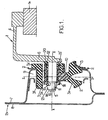
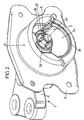
- This mounting comprises first and second rigid metal frames 1 and 2 which are joined to one another by an elastomer body 3 and which are designed to be inserted between two other rigid elements for damping and connection purposes.
- the first frame 1 for example, is designed to be connected to a load to be supported, for example a power unit 1a of a motor vehicle.
- the first frame is in the form of a double angle bracket, each of the free ends 4, 5 of which projects perpendicularly relative to a part 6 positioned substantially parallel with the vertical direction Z in which the weight of the power unit 1a is applied.
- the free end 4, for example, is a bracket joined to the power unit 1a, for example by screwing.
- first and second frames 1 and 2 may be reversed without departing from the scope of the invention.
- the elastomer body 3 is a substantially annular member surrounding the axis X and is moulded and bonded onto the second frame 2, optionally clamping a reinforcing insert 13.
- the elastomer body 3 is moulded and bonded onto a central sleeve 10 made from a plastics material, inside which the mounting bar 5 belonging to the first frame 1 fits.
- This zone 3a forms two opposite bosses 3b, which co-operate by abutting with the interior of the second frame 2 to restrict displacement of the first frame 1 relative to the second frame 2 in a direction perpendicular to the axes X and Z.
- the elastomer body 3 has various special design features. For example, its bottom annular part 3a is separated from an outer annular part 3c by a slit 3d, except on a level with a bell-shaped bottom support part 3e linking parts 3a and 3c to one another.
- the outer part 3c of the elastomer body 3 is fitted with a stop 3f in a zone opposite the part 3e.
- the sleeve 10 On a level with an end 14 positioned facing parts 7, 8 mentioned above, the sleeve 10 has a first connection means 15 comprising a zone of a truncated cone shape, for example, provided with a plurality of flexible tabs 16, of which there are three in particular and advantageously four.
- a ridge 21 manufactured in one piece with the mounting bar 5 is provided between each flexible tab 16.
- Each of the ridges projects perpendicularly to the longitudinal axis of the sleeve and fits between two contiguous tabs 16, preventing any rotary movement between the first and the second frame.
- the mounting bar 5 of the first frame 1 has a second connection means 19, matching the first means 15 and co-operating with it in a snap mechanism (i.e. by an elastic gripping action).
- This second connection means 19 comprises a shoulder or relief, for example, projecting out radially relative to the axis X.
- the tabs 16 may be displaced radially as the mounting bar 5 penetrates the sleeve 10. Once the shoulder 19 has moved past the tip of the region of the truncated cone shape formed by the first connection means 15, the flexible tabs 16 resume their initial positions and move to bear, in a zone 11, on the wall of the relief 19, thereby restricting any displacement in translation along the axis X of the end of the mounting bar 5 of the first frame 1 relative to the body 3 in the uncoupling direction.
- the shoulder 19' is made from rubber, which is compressed during mounting and acts as a spring.
- the sleeve 10 is reinforced by a tubular metal insert 12, partially embedded in the plastics material of the sleeve 10.
- the periphery of the elastomer body 3 may advantageously be reinforced in full or in part by one or more rigid inserts 13, in particular of metal, which may optionally be surrounded by the second frame 2.
- the snap connection between the two frames enables normal manufacturing tolerances to be retained, which prevents any uncoupling whilst reconciling the manufacturing and design requirements for an anti-vibration mounting comprising a reduced number of parts and costing less.
Landscapes
- Engineering & Computer Science (AREA)
- General Engineering & Computer Science (AREA)
- Manufacturing & Machinery (AREA)
- Mechanical Engineering (AREA)
- Vibration Prevention Devices (AREA)
- Springs (AREA)
- Arrangement Or Mounting Of Propulsion Units For Vehicles (AREA)
- Snaps, Bayonet Connections, Set Pins, And Snap Rings (AREA)
Description
- the free ends of the flexible tabs abut against a projection protruding radially relative to the mounting bar;
- there are at least three flexible tabs;
- there are four flexible tabs;
- the sleeve is made from a plastics material;
- the plastics sleeve is reinforced by a metal insert;
- the elastomer body has zones forming stops along the first axis and in a direction perpendicular to the first and second axes in order to restrict the extent of relative movements between the first and second frames;
- a ridge manufactured in one piece with the mounting bar fits between each flexible tab, avoiding any rotary movement between the first and second frames;
- the elastomer body is surrounded by the second frame.
- figure 1 is a view in section and in side elevation of an anti-vibration mounting as proposed by the invention;
- figure 2 is a perspective view of an anti-vibration mounting as proposed by the invention;
- figure 3 is a perspective view showing a detail of part of the mounting illustrated in figure 2.
Claims (11)
- An anti-vibration mounting comprising first (1) and second (2) rigid frames, which can be joined respectively to two rigid elements (1a,2a) to be connected, an elastomer body (3) linking the two frames to one another and being designed to support a permanent axial load along a first axis (Z), the elastomer body being joined to a sleeve (10) fitted on a mounting bar (5) belonging to the first frame (1) and extending along a second axis (X) substantially perpendicular to the first axis (Z), wherein the sleeve (10) is retained on the mounting bar (5) by a snap connection (15,19).
- An anti-vibration mounting as claimed in claim 1, wherein the sleeve (10) has an end piece of a truncated cone shape provided with a plurality of flexible tabs (16) which clip onto the mounting bar (5).
- An anti-vibration mounting as claimed in claim 2, wherein the free ends of the flexible tabs (16) abut against a relief (19) projecting radially relative to the mounting bar (5).
- An anti-vibration mounting as claimed in claim 1, wherein there are at least three flexible tabs (16).
- An anti-vibration mounting as claimed in claim 1, wherein there are four flexible tabs (16).
- An anti-vibration mounting as claimed in claim 1, wherein the sleeve (10) is made from a plastics material.
- An anti-vibration mounting as claimed in claim 1, wherein the sleeve (10) is reinforced by a metal insert (12).
- An anti-vibration mounting as claimed in claim 1, wherein the elastomer body (3) has some zones forming stops along the first axis and in a direction perpendicular to the first (Z) and second (X) axes in order to restrict the extent of relative movement between the first and second frames (1,2).
- An anti-vibration mounting as claimed in claim 1 wherein, the elastomer body (3) is surrounded by the second frame (2).
- An anti-vibration mounting as claimed in claim 1, wherein a ridge (21) manufactured in one piece with the mounting bar (5) fits between each flexible tab (16), preventing any rotary movement between the first and second frames (1,2).
- A motor vehicle comprising an engine connected to a body by at least one anti-vibration mounting as claimed in claim 1, the first axis (Z) being vertical and the second axis (X) being horizontal.
Applications Claiming Priority (3)
| Application Number | Priority Date | Filing Date | Title |
|---|---|---|---|
| US657240 | 2000-09-07 | ||
| US09/657,240 US6464214B1 (en) | 2000-09-07 | 2000-09-07 | Anti-vibration mounting for clip-fit connection means and vehicle fitted with this mounting |
| PCT/IB2001/001865 WO2002021011A1 (en) | 2000-09-07 | 2001-09-06 | Anti-vibration mounting for a clip-fit connection means and vehicle fitted with this mounting |
Publications (2)
| Publication Number | Publication Date |
|---|---|
| EP1228323A1 EP1228323A1 (en) | 2002-08-07 |
| EP1228323B1 true EP1228323B1 (en) | 2004-10-27 |
Family
ID=24636395
Family Applications (1)
| Application Number | Title | Priority Date | Filing Date |
|---|---|---|---|
| EP20010972402 Expired - Lifetime EP1228323B1 (en) | 2000-09-07 | 2001-09-06 | Anti-vibration mounting having a snap connection means and vehicle fitted with this mounting |
Country Status (7)
| Country | Link |
|---|---|
| US (1) | US6464214B1 (en) |
| EP (1) | EP1228323B1 (en) |
| JP (1) | JP2004508513A (en) |
| BR (1) | BR0107177B1 (en) |
| DE (1) | DE60106719T2 (en) |
| ES (1) | ES2231555T3 (en) |
| WO (1) | WO2002021011A1 (en) |
Families Citing this family (1)
| Publication number | Priority date | Publication date | Assignee | Title |
|---|---|---|---|---|
| DE102006018621A1 (en) * | 2006-04-21 | 2007-10-25 | Trelleborg Automotive Technical Centre Gmbh | Air-damped bearing bush |
Family Cites Families (25)
| Publication number | Priority date | Publication date | Assignee | Title |
|---|---|---|---|---|
| US1830118A (en) * | 1927-09-17 | 1931-11-03 | Hugh C Lord | Vibration dampener |
| GB808842A (en) * | 1955-06-23 | 1959-02-11 | Metalastik Ltd | Improvements in or relating to resilient supports |
| US3531144A (en) * | 1969-02-27 | 1970-09-29 | Ingersoll Rand Co | Retainer ring |
| US4884656A (en) * | 1987-12-09 | 1989-12-05 | Lord Corporation | Snap-in plate mount |
| JPH064083Y2 (en) * | 1989-10-11 | 1994-02-02 | 株式会社ニフコ | Clips for mounting panels, etc. |
| JPH0357531U (en) * | 1989-10-12 | 1991-06-03 | ||
| JP2902462B2 (en) * | 1990-08-29 | 1999-06-07 | 倉敷化工株式会社 | Sliding bush assembly |
| JP2919937B2 (en) * | 1990-09-26 | 1999-07-19 | 大成建設株式会社 | Connection structure and connection structure of panel-like material |
| JPH0749125Y2 (en) * | 1990-10-15 | 1995-11-13 | チューナー株式会社 | Supporting mechanism for rotating members |
| JPH04210134A (en) * | 1990-11-30 | 1992-07-31 | Bridgestone Corp | Vibration isolating device |
| JPH0510360A (en) * | 1991-07-05 | 1993-01-19 | Bridgestone Corp | Bracket for bush attachment |
| US5261850A (en) * | 1991-12-10 | 1993-11-16 | Mattel, Inc. | Elastic material inflation toy |
| DE4230529C2 (en) * | 1992-09-12 | 2002-04-11 | Opel Adam Ag | Motor vehicle with interchangeable rear engine module |
| JP2719999B2 (en) * | 1992-11-30 | 1998-02-25 | 澤藤電機株式会社 | Anti-vibration support device for compressor in refrigerator |
| US5310276A (en) * | 1992-12-21 | 1994-05-10 | Hutchinson | Connection device between two mechanical components |
| US5468109A (en) * | 1993-02-11 | 1995-11-21 | Franco Ferrari | Quick removable fasteners in particular for furniture |
| JPH06313457A (en) * | 1993-04-28 | 1994-11-08 | Toyoda Gosei Co Ltd | Metal/resin complex |
| JP2607094Y2 (en) * | 1993-12-22 | 2001-03-19 | 大和化成工業株式会社 | Clip mounting structure for T stud |
| JP3005369U (en) * | 1994-06-17 | 1994-12-20 | 勝市 佐藤 | Fitting device made of soft synthetic resin |
| JP3777648B2 (en) * | 1996-04-03 | 2006-05-24 | 石川島播磨重工業株式会社 | Impeller fastening structure |
| JPH1089328A (en) * | 1996-09-12 | 1998-04-07 | Sumitomo Wiring Syst Ltd | Mounting member for boss member and boss member for mounting the mounting member |
| JP3704422B2 (en) * | 1997-08-01 | 2005-10-12 | 倉敷化工株式会社 | Steering bush |
| JP3847938B2 (en) * | 1998-02-12 | 2006-11-22 | 株式会社大井製作所 | Rotating lever support structure |
| US6062763A (en) * | 1998-05-19 | 2000-05-16 | Illinois Tool Works, Inc. | Retainer for a shock mount |
| JP3507350B2 (en) * | 1998-12-16 | 2004-03-15 | ダイハツ工業株式会社 | Vehicle drive unit mounting structure |
-
2000
- 2000-09-07 US US09/657,240 patent/US6464214B1/en not_active Expired - Lifetime
-
2001
- 2001-09-06 BR BRPI0107177-7A patent/BR0107177B1/en not_active IP Right Cessation
- 2001-09-06 WO PCT/IB2001/001865 patent/WO2002021011A1/en not_active Ceased
- 2001-09-06 EP EP20010972402 patent/EP1228323B1/en not_active Expired - Lifetime
- 2001-09-06 JP JP2002525390A patent/JP2004508513A/en active Pending
- 2001-09-06 ES ES01972402T patent/ES2231555T3/en not_active Expired - Lifetime
- 2001-09-06 DE DE60106719T patent/DE60106719T2/en not_active Expired - Lifetime
Also Published As
| Publication number | Publication date |
|---|---|
| US6464214B1 (en) | 2002-10-15 |
| DE60106719D1 (en) | 2004-12-02 |
| DE60106719T2 (en) | 2005-12-22 |
| WO2002021011A1 (en) | 2002-03-14 |
| BR0107177B1 (en) | 2010-06-29 |
| BR0107177A (en) | 2002-07-02 |
| ES2231555T3 (en) | 2005-05-16 |
| EP1228323A1 (en) | 2002-08-07 |
| JP2004508513A (en) | 2004-03-18 |
Similar Documents
| Publication | Publication Date | Title |
|---|---|---|
| US5799930A (en) | Body mount assembly | |
| US20020047231A1 (en) | Mount for a shock absorber | |
| US4092078A (en) | Elastic connection for an axial joint with connecting linkage of a motor vehicle steering gear | |
| US5092703A (en) | Ball joint and method of manufacturing the same | |
| CN101688579A (en) | Anti-vibration device | |
| US5193776A (en) | Mechanism for locking angular movement of suction pad | |
| US5318373A (en) | Ball joint for motor vehicles | |
| US20010040326A1 (en) | Resilient member with deformed element and method of forming same | |
| US6729611B2 (en) | Antivibration sleeve and a motor vehicle including such a sleeve | |
| KR100226879B1 (en) | Mounting eye | |
| US9707836B2 (en) | Powertrain roll restrictor | |
| JP6909789B2 (en) | Plain bearing | |
| CA2513229C (en) | Flexible mounting assembly for a laundry appliance and method of use | |
| CN113696831A (en) | Elastic clip | |
| US6988579B2 (en) | Power unit mount structure for vehicles | |
| US6464214B1 (en) | Anti-vibration mounting for clip-fit connection means and vehicle fitted with this mounting | |
| US20070219002A1 (en) | Flexible coupling for torque-transmitting connection of two elements, and assembly | |
| EP1662187A1 (en) | Resin joint boot | |
| JP2020060222A (en) | Cylindrical vibration controller | |
| WO2002073052A1 (en) | A bushing with controlled elastic absorption of radial stress | |
| US20060272911A1 (en) | Jounce bumper, rate cup, and strut mount bottom plate | |
| CN110015335B (en) | Steering apparatus | |
| US20210246981A1 (en) | Gear shift linkage mechanism and gear shift apparatus | |
| EP4446609A1 (en) | A damper unit and a damper assembly | |
| CN222458078U (en) | Connector and connecting assembly |
Legal Events
| Date | Code | Title | Description |
|---|---|---|---|
| PUAI | Public reference made under article 153(3) epc to a published international application that has entered the european phase |
Free format text: ORIGINAL CODE: 0009012 |
|
| AK | Designated contracting states |
Kind code of ref document: A1 Designated state(s): AT BE CH CY DE DK ES FI FR GB GR IE IT LI LU MC NL PT SE TR |
|
| 17P | Request for examination filed |
Effective date: 20020503 |
|
| GRAP | Despatch of communication of intention to grant a patent |
Free format text: ORIGINAL CODE: EPIDOSNIGR1 |
|
| RBV | Designated contracting states (corrected) |
Designated state(s): DE ES FR GB IT |
|
| RTI1 | Title (correction) |
Free format text: ANTI-VIBRATION MOUNTING HAVING A SNAP CONNECTION MEANS AND VEHICLE FITTED WITH THIS MOUNTING |
|
| GRAS | Grant fee paid |
Free format text: ORIGINAL CODE: EPIDOSNIGR3 |
|
| GRAA | (expected) grant |
Free format text: ORIGINAL CODE: 0009210 |
|
| AK | Designated contracting states |
Kind code of ref document: B1 Designated state(s): DE ES FR GB IT |
|
| REG | Reference to a national code |
Ref country code: GB Ref legal event code: FG4D |
|
| REG | Reference to a national code |
Ref country code: IE Ref legal event code: FG4D |
|
| REF | Corresponds to: |
Ref document number: 60106719 Country of ref document: DE Date of ref document: 20041202 Kind code of ref document: P |
|
| REG | Reference to a national code |
Ref country code: ES Ref legal event code: FG2A Ref document number: 2231555 Country of ref document: ES Kind code of ref document: T3 |
|
| PLBE | No opposition filed within time limit |
Free format text: ORIGINAL CODE: 0009261 |
|
| STAA | Information on the status of an ep patent application or granted ep patent |
Free format text: STATUS: NO OPPOSITION FILED WITHIN TIME LIMIT |
|
| 26N | No opposition filed |
Effective date: 20050728 |
|
| ET | Fr: translation filed | ||
| PGFP | Annual fee paid to national office [announced via postgrant information from national office to epo] |
Ref country code: GB Payment date: 20060117 Year of fee payment: 5 |
|
| GBPC | Gb: european patent ceased through non-payment of renewal fee |
Effective date: 20060906 |
|
| PG25 | Lapsed in a contracting state [announced via postgrant information from national office to epo] |
Ref country code: GB Free format text: LAPSE BECAUSE OF NON-PAYMENT OF DUE FEES Effective date: 20060906 |
|
| REG | Reference to a national code |
Ref country code: FR Ref legal event code: PLFP Year of fee payment: 15 |
|
| REG | Reference to a national code |
Ref country code: FR Ref legal event code: PLFP Year of fee payment: 16 |
|
| REG | Reference to a national code |
Ref country code: FR Ref legal event code: CA Effective date: 20161110 Ref country code: FR Ref legal event code: CD Owner name: HUTCHINSON ANTIVIBRATION SYSTEMS, INC., US Effective date: 20161110 |
|
| REG | Reference to a national code |
Ref country code: DE Ref legal event code: R082 Ref document number: 60106719 Country of ref document: DE Representative=s name: MITSCHERLICH, PATENT- UND RECHTSANWAELTE PARTM, DE Ref country code: DE Ref legal event code: R081 Ref document number: 60106719 Country of ref document: DE Owner name: HUTCHINSON ANTIVIBRATION SYSTEMS INC., GRAND R, US Free format text: FORMER OWNER: PAULSTRA CRC, GRAND RAPIDS, MICH., US |
|
| REG | Reference to a national code |
Ref country code: FR Ref legal event code: PLFP Year of fee payment: 17 |
|
| PGFP | Annual fee paid to national office [announced via postgrant information from national office to epo] |
Ref country code: FR Payment date: 20170925 Year of fee payment: 17 Ref country code: DE Payment date: 20170911 Year of fee payment: 17 Ref country code: IT Payment date: 20170918 Year of fee payment: 17 |
|
| REG | Reference to a national code |
Ref country code: ES Ref legal event code: PC2A Owner name: HUTCHINSON ANTIVIBRATION SYSTEMS INC. Effective date: 20171205 |
|
| PGFP | Annual fee paid to national office [announced via postgrant information from national office to epo] |
Ref country code: ES Payment date: 20171016 Year of fee payment: 17 |
|
| REG | Reference to a national code |
Ref country code: DE Ref legal event code: R119 Ref document number: 60106719 Country of ref document: DE |
|
| PG25 | Lapsed in a contracting state [announced via postgrant information from national office to epo] |
Ref country code: IT Free format text: LAPSE BECAUSE OF NON-PAYMENT OF DUE FEES Effective date: 20180906 Ref country code: DE Free format text: LAPSE BECAUSE OF NON-PAYMENT OF DUE FEES Effective date: 20190402 |
|
| PG25 | Lapsed in a contracting state [announced via postgrant information from national office to epo] |
Ref country code: FR Free format text: LAPSE BECAUSE OF NON-PAYMENT OF DUE FEES Effective date: 20180930 |
|
| REG | Reference to a national code |
Ref country code: ES Ref legal event code: FD2A Effective date: 20191030 |
|
| PG25 | Lapsed in a contracting state [announced via postgrant information from national office to epo] |
Ref country code: ES Free format text: LAPSE BECAUSE OF NON-PAYMENT OF DUE FEES Effective date: 20180907 |