EP1227754B1 - Method for measuring an induced perturbation to determine a physiological parameter - Google Patents
Method for measuring an induced perturbation to determine a physiological parameter Download PDFInfo
- Publication number
- EP1227754B1 EP1227754B1 EP00976847A EP00976847A EP1227754B1 EP 1227754 B1 EP1227754 B1 EP 1227754B1 EP 00976847 A EP00976847 A EP 00976847A EP 00976847 A EP00976847 A EP 00976847A EP 1227754 B1 EP1227754 B1 EP 1227754B1
- Authority
- EP
- European Patent Office
- Prior art keywords
- exciter
- pressure
- waveform
- blood pressure
- signal
- Prior art date
- Legal status (The legal status is an assumption and is not a legal conclusion. Google has not performed a legal analysis and makes no representation as to the accuracy of the status listed.)
- Expired - Lifetime
Links
Images


Classifications
-
- A—HUMAN NECESSITIES
- A61—MEDICAL OR VETERINARY SCIENCE; HYGIENE
- A61B—DIAGNOSIS; SURGERY; IDENTIFICATION
- A61B5/00—Measuring for diagnostic purposes; Identification of persons
- A61B5/02—Detecting, measuring or recording pulse, heart rate, blood pressure or blood flow; Combined pulse/heart-rate/blood pressure determination; Evaluating a cardiovascular condition not otherwise provided for, e.g. using combinations of techniques provided for in this group with electrocardiography or electroauscultation; Heart catheters for measuring blood pressure
- A61B5/021—Measuring pressure in heart or blood vessels
- A61B5/022—Measuring pressure in heart or blood vessels by applying pressure to close blood vessels, e.g. against the skin; Ophthalmodynamometers
-
- A—HUMAN NECESSITIES
- A61—MEDICAL OR VETERINARY SCIENCE; HYGIENE
- A61B—DIAGNOSIS; SURGERY; IDENTIFICATION
- A61B5/00—Measuring for diagnostic purposes; Identification of persons
- A61B5/02—Detecting, measuring or recording pulse, heart rate, blood pressure or blood flow; Combined pulse/heart-rate/blood pressure determination; Evaluating a cardiovascular condition not otherwise provided for, e.g. using combinations of techniques provided for in this group with electrocardiography or electroauscultation; Heart catheters for measuring blood pressure
- A61B5/021—Measuring pressure in heart or blood vessels
- A61B5/02133—Measuring pressure in heart or blood vessels by using induced vibration of the blood vessel
Definitions
- the present invention relates to a method for noninvasively providing a determination of a patient's physiological parameter and other clinically important parameters, in particular a method of continuously monitoring the blood pressure of a patient.
- Blood pressure is the force within the arterial system of an individual that ensures the flow of blood and delivery of oxygen and nutrients to the tissue. Prolonged reduction or loss of pressure severely limits the amount of tissue perfusion and could therefore result in damage to or even death of the tissue. Although some tissues can tolerate hypoperfusion for long periods of time, the brain, heart and kidneys are very sensitive to a reduction in blood flow. Thus, during and after surgery, blood pressure is a frequently monitored vital sign. Blood pressure is affected, during and after surgery, by the type of surgery and physiological factors such as the body's reaction to the surgery. Moreover, blood pressure is manipulated and controlled, during and after surgery, using various medications. Often, these physiological factors and the given medications can result in a situation of rapidly changing blood pressure requiring immediate blood pressure measurement, and corrective action.
- noninvasive, intermittent methods that use an automated cuff device such as an oscillometric cuff
- invasive, continuous (beat-to-beat) measurements that use a catheter.
- the oscillometric cuff method typically requires 15 to 45 seconds to obtain a measurement, and should allow sufficient time for venous recovery. Thus, at best there is typically 1/2 to 1 minute between updated pressure measurements. This is an inordinately long amount of time to wait for an updated pressure reading when fast acting medications are administered. Also, too frequent cuff inflations over extended periods may result in ecchymosis and/or nerve damage in the area underlying the cuff.
- the invasive method has inherent disadvantages including risk of embolization, infection, bleeding and vessel wall damage.
- Tolles employs two sensors to detect a perturbation waveform and generate two sensor signals. The two sensor signals are compared in a phase detector. The phase difference of the sensor signals is displayed giving a signal that is capable of detecting changes in blood pressure, but which does not provide a calibrated blood pressure output.
- Salisbury similarly employs a sensor to detect a perturbation waveform and generate a single sensor signal. The sensor signal is compared against a reference signal. Based on the phase difference of the sensor signal, a universal formula is employed to determine the patient's blood pressure. Since it has been shown, for example by Landowne, that the relationship between pressure and signal propagation varies considerably from patient to patient, Salisbury's technique, based on a single formula, is not generally applicable.
- WO-A-95/28126 discloses an apparatus and method for
- the present invention describes a method for measuring the induced perturbation of a patient's body tissue to determine the patient's blood pressure and other clinically important parameters, and is characterized by the features of claim 1.
- An object of the present invention is to continuously determine a patient's blood pressure via a noninvasive sensor attached to the patient.
- a related object is to induce a perturbation into a patient's blood or blood vessel and to noninvasively measure the perturbation to determine the patient's blood pressure.
- a related object is to filter the noninvasive sensor signal into components including a natural component, an induced component and a noise component, and to determine the patient's blood pressure from the induced component.
- a further related object is to determine a relationship between a property of an induced perturbation and a property of a physiological parameter.
- a monitor for determining a patient's physiological parameter includes a calibration device configured to provide a calibration signal representative of the patient's physiological parameter.
- An exciter is positioned over a blood vessel of the patient for inducing a transmitted exciter waveform into the patient.
- a noninvasive sensor is positioned over the blood vessel, where the noninvasive sensor is configured to sense a hemoparameter and to generate a noninvasive sensor signal representative of the hemoparameter containing a component of a received exciter waveform.
- a hemoparameter is defined as any physiological parameter related to vessel blood such as pressure, flow, volume, velocity, blood vessel wall motion, blood vessel wall position and other related parameters.
- a processor is configured to determine a relationship between a property of the received exciter waveform and a property of the physiological parameter.
- the processor is connected to receive the calibration signal and the noninvasive sensor signal, and the processor is configured to process the calibration signal and.the noninvasive sensor signal to determine the physiological parameter.
- the physiological parameter measured is blood pressure.
- the present invention concentrates on the physiological parameter of blood pressure.
- the term continuous means that the physiological parameter of interest is determined over a period of time, such as during the course of surgery.
- the implementation ofportions of the invention in a digital computer is performed by sampling various input signals and performing the described procedures on a set of samples. Hence, a periodic determination of the physiological parameter of interest is within the definition of the term "continuous" .
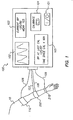
- FIG. 1 illustrates the components and configuration of an apparatus for carrying out the preferred embodiment.
- Oscillometric cuff 110 is connected to processor 100 via wire 106, and cuff 110 is responsive to processor 100 during an initial calibration step.
- Oscillometric cuff operation which is known in the art, involves an automated procedure for obtaining a blood pressure signal. The general procedure is given for clarity but is not crucial to the invention.
- an occlusive cuff is pressurized around the patient's upper arm to abate the blood flow. Then, as the pressure is slowly reduced, a transducer senses when the blood flow begins and this pressure is recorded as the systolic pressure. As the pressure is further reduced, the transducer similarly detects the pressure when full blood flow is restored and this pressure is recorded as the diastolic pressure.
- the signals representing pressure are delivered, via wire 106, to processor 100 for storage.
- An alternative blood pressure measurement technique such as manual or automated sphygmomanometry using Korotkoff sounds or "return to flow" techniques, could also be used.
- a manual measurement can be provided, for example, using a keypad. Whatever measurement technique is used, a calibration device provides a calibration signal representative of the patient's physiological parameter. In this respect, the calibration device is broadly defined to include automated or manual measurements.
- FIG. 1 shows an exciter 202 attached to the patient's forearm above the radial artery.
- the exciter 202 is a device for inducing a perturbation of the patient's body tissue, and is controlled by the processor 100 via tube 107.
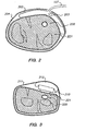
- FIG. 2 shows a cross section of the exciter and its components.
- the exciter 202 is an inflatable bag attached to the processor via air tube 107. It is fixed in place near - an accessible artery 220 by holddown device 204 which can be a buckle, adhesive strap or other device.
- the exciter drive voltage or current can be used as the reference signal and the exciter sensor 203 is a simple current or voltage sensor. In such a case, a signal representative of the exciter current or voltage is delivered to the processor via wire 108.
- the exciter sensor may also be contained within the processor and connected to the exciter by an electrical connection such as a wire.
- processor 100 is attached to the exciter via tube 107.
- the processor 100 controls the pressure in exciter 202 with a transducer and diaphragm.
- a transducer is a device that transforms an electrical signal to physical movement
- a diaphragm is a flexible material attached to the transducer for amplifying the movement.
- An example of this combination is a loudspeaker.
- the diaphragm forms part of an airtight enclosure connected to air tube 107 and an input to initialize the pressure.
- the transducer and air tube 107 and exciter 202 can be miniaturized and combined into a single exciter element capable of acting as a vibrating air filled bag connected to the processor by an electrical drive signal alone, in the case that a source of substantially constant pressure such as a spring is included in the exciter, or by an electrical drive signal and connection to a source of substantially constant pressure for the bag.
- a source of substantially constant pressure such as a spring
- the exciter may equally well be coupled to the arm through a fluid medium such as air, or by a solid medium such as a gel.
- the pressure is initially established via the initialization input and then the pressure is varied by an electrical signal delivered to the transducer; the diaphragm produces pressure variations in the tube in response to the transducer movement.
- the processor by delivering an oscillating electrical signal to the transducer, causes oscillating exciter pressure.
- the exciter responds by perturbing the patient's tissue and inducing a transmitted exciter waveform into the patient. This transmitted exciter waveform should be considered to be a vibrational exciter waveform since it involves a vibrational perturbation of the tissue.
- the perturbation excites the tissue 221 and blood vessel 220 below the exciter and causes the transmitted exciter waveform to radiate within the patient's body, at least a portion of which travels along the blood filled vessel.
- the excitation waveform can be sinusoidal, square, triangular, or of any suitable shape. Experiments conducted to determine a range of satisfactory perturbation frequencies found that the range of 20-1000 Hz works well. It is anticipated that frequencies of lesser than 20 Hz and greater than 1000 Hz will also work well, and it is intended that this specification cover all frequencies insofar as the present invention is novel.
- FIG. 1 further shows a noninvasive sensor 210 placed at a distance from the exciter on the patient's wrist.
- the noninvasive sensor is connected to the processor 100 via wire 109.
- FIG. 3 shows a cut-away view of the noninvasive sensor 210 placed over the same radial artery 220 as the exciter.
- the sensor 210 is fixed in place near the artery 220 by holddown device 211 which can be a buckle, adhesive strap or other device.
- the holddown device 211 also includes a baffle 212 to reduce noise, where the baffle is a pneumatic bag pressurized to hold the sensor 210 at a constant pressure against the patient, for example at a pressure of 10 mm Hg.
- baffle 212 can be any suitable device such as a spring or foam pad.
- the noninvasive sensor 210 is responsive to at least one hemoparameter of the patient and generates a signal in response thereto.
- a hemoparameter is defined as any physiological parameter related to vessel blood such as pressure, flow, volume, velocity, blood vessel wall motion, blood vessel wall position and other related parameters.
- a piezoelectric sensor is used to sense arterial wall displacement, which is directly influenced by blood pressure. It will be clear to one skilled in the art that a microphone or other sensor could be used as the noninvasive sensor.
- the sensor may be connected to the arm by a fluid or solid coupling such as an air filled cavity or a gel.
- the senor is positioned over the radial artery 220 and it is responsive to pressure variations therein; as the pressure increases, the piezoelectric material deforms and generates a signal corresponding to the deformation.
- the signal is delivered to the processor 100 via wire 109.
- FIG. 1 also shows the processor 100 that has a control panel for communicating information with the user.
- a power switch 101 is for turning the unit on.
- a waveform output monitor 102 displays the continuous blood pressure waveform for medical personnel to see. This waveform is scaled to the pressures determined by the processor, and output to the monitor.
- a digital display 103 informs the user of the current blood pressure; there is a systolic over diastolic and mean pressure shown.
- a calibrate button 104 permits the user to calibrate the processor at any time, by pressing the button.
- the calibration display 105 shows the user the blood pressure at the most recent calibration, and also the elapsed time since calibration.
- the processor maintains a record of all transactions that occur during patient monitoring including calibration blood pressure, calibration times, continuous blood pressure and other parameters, and it is anticipated that additional information can be stored by the processor and displayed on the control panel.
- the noninvasive sensor signal in addition to a natural hemoparameter, contains a component indicative of the exciter waveform traveling through the patient.
- the exciter component is designed to be small in comparison to the natural hemoparameter, it contains valuable information. Therefore, the processor is used to separate the exciter waveform from the natural hemoparameter, and to quantify the respective components to determine the patient's blood pressure.
- FIG. 4a shows a natural blood pressure waveform where the minimum represents the diastolic pressure and the maximum represents the systolic pressure.
- This waveform has a mean arterial pressure (MAP) that is a convenient reference for purposes of determining the DC offset of the waveform.
- MAP mean arterial pressure
- Example pressure values are 80 mm Hg diastolic and 120 mm Hg systolic respectively with a MAP DC offset of 90 mm Hg.
- FIG. 4b shows an operational illustration of the arterial waveform; an exciter waveform superimposed on a natural blood pressure waveform.
- the exciter induces the exciter waveform into the arterial blood at a first location and the exciter waveform becomes superimposed on the natural waveform. Since the exciter waveform is small compared to the patient's natural waveform, the natural waveform dominates as shown in FIG. 4b.
- the noninvasive sensor signal contains information regarding both the natural waveform and the exciter waveform.
- the processor 100 is designed to separate the constituent components of the noninvasive sensor signal to continuously determine the patient's blood pressure as is discussed below.
- FIG. 5 depicts a schematic diagram of an apparatus for carrying out the present invention is an oscillometric cuff controller 121 for controlling the oscillometric cuff and determining the readings therefrom to generate a signal representing the patient's blood pressure.
- an induced wave frequency generator 131 coupled to a pressure transducer 133 that transforms an electrical input to a pressure output.
- the transducer output is connected to the exciter 202 and controls the exciter's oscillations for inducing the exciter waveform into the patient's arterial blood.
- the output of the exciter sensor 203 is fed to a band pass filter 134.
- This filter 134 separates the high frequency signal responsive to the transducer pressure and delivers the resulting signal to RMS meter 135 and to lock-in amplifier 143 reference input.
- the RMS meter output is sampled at a rate of 200 samples per second with a 14 bit resolution and delivered to computer 150. It is anticipated that the sampling rate and resolution can be varied with good results.
- the output of the noninvasive sensor is fed to a charge amplifier 140 that delivers a resulting signal to a low pass filter 141 and a band pass filter 142.
- These filters separate the noninvasive sensor signal into two constituent components representing an uncalibrated natural blood pressure wave and a received exciter waveform respectively.
- the low pass filter output is sampled at a rate of 200 samples per second with 14 bit resolution and delivered to computer 150, and the band pass filter output is delivered to the lock-in amplifier 143 signal input.
- the lock-in amplifier 143 receives inputs from band pass filter 134 as reference and band pass filter 142 as signal, which are the exciter sensor signal (transmitted exciter waveform) and noninvasive sensor exciter signal (received exciter waveform) respectively.
- the lock-in amplifier uses a technique known as phase sensitive detection to single out the component of the noninvasive sensor exciter signal at a specific reference frequency and phase, which is that of the exciter sensor signal.
- the amplifier 143 produces an internal, constant-amplitude sine wave that is the same frequency as the reference input and locked in phase with the reference input.
- This sine wave is then multiplied by the noninvasive sensor exciter signal and low-pass filtered to yield a signal proportional to the amplitude of the noninvasive sensor signal multiplied by the cosine of the phase difference between the noninvasive exciter signal and the reference. This is known as the in-phase or real output.
- the amplifier 143 also produces an internal reference sine wave that is 90 degrees out-of-phase with the reference input. This sine wave is multiplied by the received exciter signal and low-pass filtered to yield a signal proportional to the amplitude of the noninvasive sensor signal multiplied by the sine of the phase difference between the noninvasive sensor exciter signal and the reference. This is known as quadrature or imaginary output.
- the amplifier 143 then provides the computer 150 with information regarding the real and imaginary components of the received exciter signal as referenced to the phase of the transmitted exciter signal. Alternately, the amplifier can provide components representing the magnitude and phase of the received exciter signal. In the preferred embodiment, the amplifier output is sampled at a rate of 200 samples per second with a 14 bit resolution. It is anticipated that the sampling rate and resolution can be varied with good results.
- the computer 150 receives input from the oscillometric cuff controller 121, RMS meter 135, low pass filter 141 and lock-in amplifier 150.
- the computer 150 also receives input from the user interface panel 160 and is responsible for updating control panel display information.
- the computer 150 executes procedures for further separating constituent components from the noninvasive sensor signal and attenuating the noninvasive sensor noise component as shown in FIG. 6.
- FIG. 6 is a processing flowchart that represents the operation of the FIG. 5 computer 150.
- the operation begins at step 702 with the receipt of an initial calibration measurement; noninvasive sensor signal and exciter sensor signal.
- Step 704 chooses the blood pressure waveform segment for pulse reference, which is important for continuity of measurement from pulse to pulse and for consistency over periods of time between calibration measurements.
- the diastolic pressure low-point
- any point of the waveform can be chosen such as the systolic pressure or mean arterial pressure (MAP).
- MAP mean arterial pressure
- Step 706 is a filter step where the noninvasive sensor (received) exciter waveform is separated into signal and noise components.
- the noise components may have many sources, one of which is a signal derived from the exciter that travels to the noninvasive sensor by an alternate path, other than that along the artery taken by the signal of interest. Examples include bones conducting the exciter waveform and the surface tissue such as the skin conducting the exciter waveform. Additional sources of noise result from patient movement. Examples include voluntary patient motion as well as involuntary motion such as movement of the patient's limbs by a physician during surgery.
- FIGS. 7a-c illustrate the principles of the received exciter signal filtering.
- the received exciter waveform V d is represented by a collection of points that are generated in the complex plane by the real and imaginary outputs of the lock-in amplifier 143 which is monitoring the noninvasive sensor signal.
- FIG. 7a represents the received exciter waveform V d in the absence of noise.
- V d is the same as vector V w (t) which has a magnitude and phase corresponding to the received exciter signal.
- the magnitude of V w (t) remains constant, but the angle periodically oscillates from a first angle representing a lesser pressure to a second angle representing a greater pressure. Note that in the absence of noise, the arc has a center at the origin.
- FIG. 7b represents the received exciter waveform V d in the presence of noise, which is indicated by vector V n .
- Vector V d has a magnitude and phase according to the noninvasive sensor exciter waveform plus noise.
- vector V d (t) defines a collection of points forming an arc having a common point V c equidistant from each of the collection of points.
- the vector V w (t) from V c to the arc corresponds to the true magnitude and phase of the noninvasive signal exciter waveform.
- the vector V n represents noise and, once identified, can be removed from the noninvasive sensor waveform.
- the filter step removes the V n noise component and passes the V w (t) signal exciter component on to step 708.
- V w (t) the magnitude of V w (t) remains constant over the time of a pulse.
- the attenuation of the exciter waveform as it propagates along the artery is pressure dependent, and in those cases the magnitude of V w (t) can vary during the pulse in a way that is correlated to pressure.
- V d the shape of the figure traced out in the complex plane by the vector V d will deviate from a perfect circle segment.
- a typical shape is that of a spiral with a form that can be predicted theoretically.
- the functioning of this filter step under such circumstances is conceptually similar to that described above, except that the elimination of the noise vector V n must involve location of the origin of a spiral rather than of the center of a circle.
- Step 708 determines if the pulse is valid.
- the processor checks the constituent components of the noninvasive sensor signal to insure that the components are within acceptable clinical norms of the patient. For example, the processor can determine whether the new pulse is similar to the prior pulse, and if so, the new pulse is valid.
- Step 720 processes the signal exciter waveform V w (t) to determine the DC offset.
- the processor determines the offset when the vector V w (t) reaches its lowest phase angle (i.e., the maximum clockwise angle of FIG. 7a); this is the diastole phase angle ⁇ w(dias).
- a calibration diastolic measurement is stored by the processor at calibration as P D0 .
- Also stored by the processor is a relationship denoting the relationship between the velocity of an exciter wave and blood pressure. This relationship is determined by reference to a sample of patients and is continuously updated by reference to the particular patient after each calibration measurement.
- FIG. 8a-c are graphical illustrations showing clinically determined relationships between the exciter waveform and blood pressure.
- FIG. 8b represents the relationship between phase and pressure at a frequency of 150 Hz; other frequencies have relationships that are vertically offset from the line shown.
- the pressure-velocity relationship represents the storage of this graphical information either in a data table or by an analytical equation.
- Step 721 determines the predicted diastolic pressure from the information in Step 720.
- the processor continuously determines the change in diastole from one pulse to the next by referencing the position of the signal exciter vector V w (t), at ⁇ w(dias), with respect to the stored pressure-velocity relationship.
- the pressure-velocity relationship is continuously updated based on calibration measurement information gained from past calibrations of the patient.
- a set of established relationships is used to develop and interpret information in the table and to relate the information to the sensor signal components.
- a known relationship exists between blood pressure and exciter waveform velocity.
- many other relationships are known: a relationship exists between velocity and wavelength, the greater the velocity the longer the wavelength ; and a relationship exists between wavelength and phase, a change in wavelength will result in a proportional change in phase.
- a relationship exists between blood pressure and phase, and a change in blood pressure will result in a proportional change in phase. This is the basis for the offset prediction.
- P D the new DC offset diastolic pressure
- P D the new DC offset diastolic pressure
- This prediction is made based on the diastolic pressure at calibration P D0 plus the quotient of the phase difference between calibration ⁇ w D0 and the present time ⁇ w(dias) and the pressure-velocity relationship stored in processor memory as rate of change of exciter waveform phase to pressure d( ⁇ w D )/dP.
- P D pred P D ⁇ 0 + ⁇ ⁇ w dias - ⁇ ⁇ w D ⁇ 0 d ⁇ ⁇ w D / dP
- Step 722 displays the predicted diastolic pressure.
- Step 730 determines the noninvasive sensor exciter waveform phase and velocity. This determination is made based on the comparison, of the noninvasive sensor exciter waveform with the exciter sensor waveform.
- Step 731 determines the noninvasive sensor exciter waveform amplitude from the noninvasive sensor signal.
- Step 732 determines the exciter waveform pressure P w by multiplying the exciter sensor waveform magnitude V c by the ratio of the calibrated exciter waveform pressure P w (cal) to the calibrated exciter sensor waveform magnitude V c (cal).
- P w V c * P w cal V c cal
- Step 734 determines if the calibration values are still valid.
- an "Internal Consistency" trigger technique is employed to determine the validity of the data and to selectively trigger recalibration. This is called Internal Consistency Analysis and is described under that heading below.
- Step 736 predicts a new pulse pressure P p (pred) by multiplying the exciter waveform pressure P w by the ratio of the detected pulsatile voltage V p to the detected exciter waveform magnitude V w .
- P p pred P w * V p V w
- This prediction uses the noninvasive sensor exciter waveform to determine the pressure difference between the diastole and systole of the natural blood pressure waveform. For example, if a noninvasive sensor exciter magnitude V w of 0.3 V relates to a pressure variation P w of 1 mm Hg and the noninvasive sensor waveform V p varies. from -6 V to +6 V, then the noninvasive sensor waveform represents a pulse pressure excursion P p (pred) of 40 mm Hg.
- Step 760 predicts a new systolic pressure P(pred) by adding the predicted diastolic P D (pred) and pulse pressures P p (pred).
- P s pred P D pred + P p pred
- the diastole P D (pred) is 80 mm Hg (DC offset) and the pulse P p (pred) represents a difference of 40 mm Hg then the new systolic P S (pred) is 120 mm Hg. Then the new systolic pressure is displayed.
- the values determined for P S (pred) and P D (pred) can be displayed numerically.
- the output waveform for display 102 can be displayed by scaling the noninvasive sensor natural blood pressure waveform prior to output using gain and offset scaling factors so that the output waveform has amplitude, P p (pred), and DC offset, P D (pred), equal to those predicted in the above process.
- the scaled output waveform signal can also be output to other instruments such as monitors, computers, processors and displays to be used for display, analysis or computational input.
- Step 750 is taken when step 734 determines that the prior calibration is no longer reliable as described above.
- a calibration step activates the oscillometric cuff 201 and determines the patient's blood pressure, as described above.
- the processor 100 uses the calibration measurements to store updated pressure and waveform information relating to the DC offset, blood pressure waveform and exciter waveform.
- the updated variables include calibration pulse pressure P p (cal), calibration exciter sensor waveform magnitude V c (cal); diastolic pressure P D0 , diastolic exciter waveform phase ⁇ w D0 , the rate of change of exciter waveform phase to pressure d( ⁇ w D )/dP and calibration exciter waveform pressure P w (cal).
- P w cal P p cal * V w V p
- FIGS. 9a-b represent a modification to the previous method.
- the initial processing steps 702, 704, 706, 708, 730 and 731 represented in the flow chart of FIG. 9 are substantially similar to those described in the previous embodiment depicted in FIG. 6.
- the constant ⁇ 0 is determined in advance either analytically or empirically, and is dependent on the details of the geometry of the apparatus.
- step 730 therefore, use of the ⁇ (t) equations allows determination of the velocity, or pseudo-velocity, Vel(t) as a function of time.
- step 801 the values of velocity at the systolic and diastolic points of the cardiac cycle are determined as Vel S and Vel D . These correspond to the points of minimum and maximum phase delay or to the points of maximum and minimum amplitude of the naturally occurring blood pressure wave detected by the noninvasive sensor.
- Use of the pressure-velocity relationship stored in the processor is then made to transform the values of velocity at systolic and diastolic points in time to values of pressure.
- step 805 the calculated pressures are displayed as numbers, with a typical display comprising display of mean, systolic and diastolic values of the pressure waveform in digital form, together with the observed pulse rate.
- the values of P D (pred) and P S (pred) are used to determine appropriate gain and DC offset scaling parameters by which the naturally occurring blood pressure waveform detected by the noninvasive sensor is scaled prior to output in step 806 as a time varying waveform, shown as 102 in FIG. 1.
- step 750 involves a calibration step initiated when step 734 determines that the prior calibration is no longer reliable.
- the pressure-velocity relationship is determined and stored in the processor in the form of a table or of an analytical relationship.
- values of gain Pp(pred) and offset P D (pred) are determined and used to scale the noninvasive sensor natural blood pressure waveform to provide a time varying output waveform representative of the patient's blood pressure.
- the natural blood pressure waveform monitored by the noninvasive sensor is not used in the determination of the output blood pressure waveform.
- exciter waveform velocity is measured many times during a cardiac cycle (typically 50-200 times per second) and the resultant determinations of pressure are used to construct the output time varying blood pressure waveform. This process is described below with reference to FIG. 10.
- the natural blood pressure waveform is not scaled and the noninvasive sensor need not have significant sensitivity to the naturally occurring physiological parameter waveform . Therefore, there is no need to separate the data into pulse segments as in step 704 of FIG. 6.
- This feature greatly simplifies the computational task.
- An additional advantage of this technique is that all of the information used in the analysis process is encoded in the exciter waveform, which is typically at a high frequency compared with that of both the natural blood pressure waveform and that of any artifact signals introduced by patient motion or respiration. Since all of these lower frequency signals can be removed by electronic filtering, this technique is extremely immune to motion induced artifact and similar sources of interference that might otherwise introduce errors into the measurement.
- the initial processing steps 702, 706, 731 and 730 are substantially similar to those of previously described methods.
- the amplitude and phase of the exciter waveform determined in step 731 are continuous functions of time.
- the exciter waveform phase is converted to exciter waveform velocity as described previously, which is also a continuous function of time.
- step 806 the entire time dependent waveform is displayed as waveform 102.
- an important step involves the conversion of a measured phase to a deduced exciter waveform velocity, and conversion of that value to a pressure.
- this process is integral to the calculation of the DC offset pressure P D0 .
- this process is integral to determination of P S and P D .
- the process is integral to the determination of pressure at each point in time for which an output value is to be displayed as part of a "continuous" pressure waveform display.
- the relationship between pressure and velocity is dependent on many factors including the elastic properties of the artery along which the exciter waveform travels. This relationship varies considerably between patients, and must therefore be determined on a patient by patient basis, although a starting relationship derived from a pool of patients can be used.
- This determination occurs during step 750 in each of the methods described in FIGS. 6, 9, and 10, and the relationship is stored in the processor in either a tabular form, or as an analytical relationship.
- step 734 in FIGS. 6, 9 and 10 a variety of parameters are examined to determine whether the system calibration continues to be acceptable. As part of that process, it is determined whether the existing pressure-velocity relationship continues to be valid. If not, a recalibration can be initiated. Such a determination can be performed using techniques described earlier or those using multiple perturbations described below. One aspect of the multiple perturbation determination is presented under the heading Internal Consistency Analysis.
- a method in which the apparatus further induces a second exciter waveform into the arterial blood.
- An example second exciter waveform is one that has a frequency different from that of the first exciter waveform. It is noted that although the discussion of the second method concentrates on a second exciter wave, any number of two or more exciter waves can be used to determine the perturbation velocity measurement.
- processor 100 In operation, processor 100 generates two exciter waveforms and communicates the waveforms to the exciter 202 via air tube 107.
- the exciter 202 responds by inducing both exciter waveforms into the patient.
- Noninvasive sensor 210 generates a signal responsive to a hemoparameter and transmits the signal to the processor 100 via wire 109.
- the exciter may also be an element, such as a loudspeaker, physically attached to the body, in which case the exciter waveforms are sent from the processor to the exciter by means of an electrical connection or wire.
- the processor filters the noninvasive sensor signal into components of the natural waveform, a first exciter waveform, a second exciter waveform and noise.
- the processor determines the phase relationship of the first exciter waveform to a first reference input and determined the phase relationship of the second exciter waveform to a second reference input.
- the processor then generates a plurality of points, the slope of which relates to the velocity of the exciter waveform. This is shown in FIG. 8c, where the slope of the line is - 2 ⁇ d/Vel, and where d is distance and Vel is velocity. Since the distance is fixed and the slope is related to blood pressure, and since the slope changes based on changes in blood pressure, the velocity of the exciter waveform is determined.
- phase velocity or of a pseudo-phase velocity in the case that the value of n of the phase equation (7) can not be uniquely determined.
- these values need not always agree.
- phase, group and pseudo-velocity are monotonically varying functions of pressure.
- a measurement of any one of the three is a basis for a pressure prediction, so long as the appropriate pressure-velocity relationship is used.
- FIG. 8a shows the relationship of velocity to pressure.
- FIG. 11 Another embodiment of an apparatus useful for carrying out the invention is depicted in FIG. 11 showing a cross section of an exciter 202 and noninvasive sensor 210 at the same position above the blood vessel 220.
- the proximate location of the exciter and the sensor permits measurement of the blood vessel's response to the perturbations.
- the noninvasive sensor is responsive to a hemoparameter such as blood flow or blood volume. These parameters can be measured with a sensor such as a photoplethysmograph. Detected changes in the blood vessel due to the natural pulsatile pressure are calibrated using external exciter pressure oscillations and compared against the sensor signal by the processor.
- ICA Internal Consistency Analysis
- the system may be physiological or otherwise.
- the multiple frequency information may be in the form of discrete or continuous frequency content. The information may be utilized simply, such as in the dependence of a given parameter on frequency, or in more complex ways, such as in the dependence of two non-frequency parameters on each other while taking advantage of the range of parameter space spanned by the data from a range of frequency.
- ICA is used in a monitor for determining the blood pressure of a patient.
- ICA is used to determine when the state of the patient has changed in such a way as to make desirable either a recalibration of the monitoring system, or a correction to the measurement to compensate said change of state of the patient.
- the use of ICA for such purpose is described in detail for the case of monitoring of the blood pressure of a patient.
- the physiological state of an artery over the time scale of a blood pressure monitoring period is determined primarily by the level of activity of the smooth muscle component of the artery wall.
- the level of smooth muscle activity affects both the elastic and viscous properties of the artery wall.
- the elastic properties of the wall are the main determinants (although viscous properties are involved as well) of the relationship between velocity and pressure (the V-P relationship - see equation 10). This is equally true of relationships between pseudo-velocity or phase and blood pressure.
- the viscous properties of the wall have a significant influence on a number of observable quantities or relationships, such as the dependence of the propagation velocity on frequency, the propagation attenuation, and others.
- These observable quantities or relationships can be used to monitor the physiological state of the artery, and hence to monitor the validity of a previous V-P relationship calibration. These observable quantities or relationships may also be used to continuously track, calculate the changes in, and deduce the current V-P relationship.
- the D quantity was calculated as follows. First calculate the propagation velocities for the frequencies of 300, 400, 500, 600, and 700 Hz as a continuous function of time as the blood pressure pulses. Take the mean of these velocities over a pulse, to produce the velocity at Mean Arterial Pressure (MAP). Take a linear regression of the velocity at MAP vs. frequency using the valid data from all five frequencies. The slope of this line is the dispersion (D). This is an example of a utilization of the multiple frequency information, because the calculated quantity is a relationship between another parameter and frequency.
- MAP Mean Arterial Pressure
- the attenuation (A) quantity was calculated as follows. First calculate the propagation phase delays for the frequencies of 300, 400, 500, 600, and 700 Hz as a continuous function of time as the blood pressure pulses. Also calculate the propagated amplitude of the exciter waveform (relative to the injected initial amplitude) for the frequencies of 300, 400, 500, 600, and 700 Hz. Calculate the quantity In(Gv 2 /sin(kL/2)) for each frequency, where G is the relative propagated amplitude, v is the propagation velocity, L is the exciter length, and k is the propagation wave vector. Take a linear regression of ln(Gv 2 /sin(kL/2)) vs.
- dispersion (D) is calculated at MAP, but it could also be calculated at a different constant blood pressure.
- attenuation (A) utilizes an intercept of the regression of ln(Gv 2 /sin(kL/2)) vs. propagation phase, but the slope of this line is another useful quantity.
- FIG. 12 is an example flow chart of an embodiment using the above observable quantities or relationships to implement a recalibration triggering technique.
- the parameters describing the behavior of the system that depend on what state the system is in (such as the relationship between velocity and pressure described above), which we are not generally monitoring between calibrations but rather utilizing in the signal processing to produce a calculated output (such as the monitored blood pressure), are denoted by the term "state parameters" SP.
- each of the terms “trigger parameter” and “state parameter” may indicate parameters of one or more dimensions.
- the dispersion parameter (D) described above which is a trigger parameter (TP)
- TP is one numerical scalar value and is, hence, one dimensional.
- the combination of D and A is considered a two dimensional trigger parameter.
- the V-P relationship described above as the primary state parameter is two dimensional if the relationship is modeled as a line, but in general could take on higher or lower dimension.
- trigger parameter TP is understood to encompass both the possibility of a single-dimensional and multi-dimensional TP.
- the term state parameter SP is understood to encompass both the possibility of a single-dimensional and multi-dimensional SP. The same concepts can be applied to more complicated quantities using more sophisticated vector, matrix, or tensor mathematics if necessary.
- SP2 F(SP1, TP1, TP2). That is to say SP at time 2 is a function of SP at time 1, TP at time 1, and TP at time 2.
- the specification of the function F shown as steps 904 and 918 in FIG. 12 can be accomplished in a number of ways.
- the simplest way to produce an initial F is to use a pool of previously collected patient data, containing information on both TP and SP over a range of time and conditions, to develop an approximation of the function. If this initial approximation is found to produce acceptable results in testing, there is no need for step 918. If testing shows that the initial approximation of F is inadequate, F can be updated for each patient (as in step 918) using the information obtained by the calibration process. It may be sufficient to rely on calibrations that occur for other reasons to accomplish this updating process, or the device could undergo a series of planned calibrations specifically for this purpose.
- both initial and subsequent shown as step 906 in FIG. 12 SP1 is determined from the combination of information from the noninvasive sensor signal and from the calibration device, and TP1 Is determined from the noninvasive sensor signal.
- time 1 is the time of the last calibration
- time 2 is the subsequent time of continuous, monitoring operation.
- the device Given the continuous noninvasive sensor signal, and the SP 1 obtained by the previous calibration, the device can then produce an output blood pressure, as is shown in step 916.
- the device can calculate TP2 as is shown in step 910.
- the device Given TP2, SP1 and TP1 combined with the function F, the device can estimate the current SP2 as is shown in step 912.
- step 920 replaces step 916, which is not performed.
- step 914 the current estimate of SP2 is compared to the SP1 which was calculated at the last calibration. If the change in SP exceeds a predetermined recalibration threshold, the device is instructed to perform a new calibration in step 906. If the change in SP does not exceed the predetermined recalibration threshold, the device loops back to step 908 to continue acquiring the noninvasive sensor signal and producing blood pressure output. Specification of the recalibration threshold is based on the amount of change in SP that is tolerable before unacceptably inaccurate results are produced. Step 918, shown in dotted lines, is optional. Step 920, shown in dotted lines, is an optional replacement for step 916.
- a possible modification to the technique includes deciding when to recalibrate based on changes in TP rather than on the changes in SP that are calculated from the changes in TP .
- variables D and or A include but are not limited to the following: (a) the slope or intercept of a relationship between amplitude (G) and phase of the signal exciter waveform that is expressed in a different functional form than the example used above of ln(Gv 2 /sin(kL/2)) or various comparative measures of such slope or intercept derived using differing frequency combinations; (b) the difference between the phase velocity or group velocity of the signal exciter waveform (or the intercept of the line of best fit to data on a graph of omega versus k, where omega is equal to frequency times two pi); (c) various pulse shape characteristics of either the physiological parameter waveform or the exciter signal velocity waveform such as the ratio of the power in components of frequency greater than 5 Hz to the total power in components of greater than 0.2 Hz (or differences between these two waveforms or between waveforms from different exciter frequencies or different exciters
- ICA The general philosophy of ICA is to use multiple parameters to examine the internal consistency of information derived in different ways from several sources.
- a further embodiment of ICA involves the use of multiple exciter waveforms as described in section E. Each of these frequencies of perturbation can be used to derive an independent determination of a physiological parameter using the techniques described in this invention. So long as these independent determinations are in reasonable agreement, the system can be allowed to continue to monitor the physiological parameter. If the independent determinations differ by more than some threshold, then a recalibration can be triggered.
- the velocity of propagation of the cardiac pulse between two locations on the body is measured using techniques such as are described in US 5,785,659 .
- This velocity is also related to blood pressure and can be used as an independent predictor of blood pressure once it has been calibrated appropriately.
- Various changes in this velocity, or differences in the pressure predicted using it and the pressure predicted using the techniques of this invention can be used to trigger a recalibration.
- Additional embodiments include an embodiment in which two or more detectors are positioned along the artery at different distances from a single exciter, and an embodiment in which two or more exciters are positioned along the artery at different. distances from one or more detectors.
- the information obtained from each exciter detector pair can be analyzed independently.
- the multiply redundant measurements of pressure that result can be combined to provide a single pressure determination that may be both more accurate and more immune from noise, motion artifact and other potential error sources. Similar redundancy can be achieved in the embodiments that use multiple exciter waveforms by analyzing the results at each frequency independently and combining the results to provide enhanced robustness.
- any combination of more than two elements allows the value of n in the phase equation (7) to be uniquely determined so long as the spacing of two of the elements is sufficiently small to be less than a wavelength of the propagating perturbation. Since the possible range of perturbation wavelengths at a given-pressure can be determined from a pool of patients, selection of the appropriate spacing is straightforward and can be incorporated into the geometrical design of the device.
- a close relationship between physiological parameters and hemoparameters supplies valuable information used in the present invention.
- the perturbation of body tissue and sensing the perturbation also supplies valuable information used in the present invention.
- Calibration signals for the present invention can be obtained from a variety of sources including a catheter, manual determination, or other similar method.
- the DC offset for the physiological parameter waveform can be obtained in a variety of ways for use with the present invention.
- the exciter preferably uses air, but any suitable fluid or solid can be used.
- various exciter techniques can be used for inducing an exciter waveform into the patient such as an acoustic exciter, an electromagnetic exciter and an electromechanical exciter (e.g. piezoelectric device).
- Noninvasive sensors have been developed for sensing hemoparameters. These sensor types include piezoelectric, piezoresistive, microphones, impedance plethysmograph, photoplethysmograph, various types of strain gages, air cuffs, tonometry, conductivity, resistivity and other devices.
- the present invention can use any sensor that provides a waveform related to the hemoparameter of interest.
Landscapes
- Health & Medical Sciences (AREA)
- Life Sciences & Earth Sciences (AREA)
- Cardiology (AREA)
- Vascular Medicine (AREA)
- Heart & Thoracic Surgery (AREA)
- Medical Informatics (AREA)
- Biophysics (AREA)
- Pathology (AREA)
- Engineering & Computer Science (AREA)
- Biomedical Technology (AREA)
- Physiology (AREA)
- Physics & Mathematics (AREA)
- Molecular Biology (AREA)
- Surgery (AREA)
- Animal Behavior & Ethology (AREA)
- General Health & Medical Sciences (AREA)
- Public Health (AREA)
- Veterinary Medicine (AREA)
- Ophthalmology & Optometry (AREA)
- Measuring Pulse, Heart Rate, Blood Pressure Or Blood Flow (AREA)
Abstract
Description
- The present invention relates to a method for noninvasively providing a determination of a patient's physiological parameter and other clinically important parameters, in particular a method of continuously monitoring the blood pressure of a patient.
- Blood pressure is the force within the arterial system of an individual that ensures the flow of blood and delivery of oxygen and nutrients to the tissue. Prolonged reduction or loss of pressure severely limits the amount of tissue perfusion and could therefore result in damage to or even death of the tissue. Although some tissues can tolerate hypoperfusion for long periods of time, the brain, heart and kidneys are very sensitive to a reduction in blood flow. Thus, during and after surgery, blood pressure is a frequently monitored vital sign. Blood pressure is affected, during and after surgery, by the type of surgery and physiological factors such as the body's reaction to the surgery. Moreover, blood pressure is manipulated and controlled, during and after surgery, using various medications. Often, these physiological factors and the given medications can result in a situation of rapidly changing blood pressure requiring immediate blood pressure measurement, and corrective action.
- Because of changes in the patient's blood pressure, constant monitoring is important. The traditional method of measuring blood pressure is with a stethoscope, occlusive cuff and pressure manometer. However, this technique is slow, subjective in nature, requires the intervention of a skilled clinician and does not provide timely readings frequently required in critical situations.
- For these reasons, two methods of measuring blood pressure have been developed: noninvasive, intermittent methods that use an automated cuff device such as an oscillometric cuff; and invasive, continuous (beat-to-beat) measurements that use a catheter.
- The oscillometric cuff method typically requires 15 to 45 seconds to obtain a measurement, and should allow sufficient time for venous recovery. Thus, at best there is typically 1/2 to 1 minute between updated pressure measurements. This is an inordinately long amount of time to wait for an updated pressure reading when fast acting medications are administered. Also, too frequent cuff inflations over extended periods may result in ecchymosis and/or nerve damage in the area underlying the cuff. The invasive method has inherent disadvantages including risk of embolization, infection, bleeding and vessel wall damage.
- To address the need for continuous, noninvasive blood pressure measurement, several systems were developed. One approach relies on blood pressure values in a patient's finger as indicative of the patient's central blood pressure, as in the cases of Penaz,
U.S. Pat. No. 4,869,261 and H. Shimazu, Vibration Techniques for Indirect Measurement of Diastolic Arterial Pressure in Human Fingers, Med. and Biol. Eng. and Comp., vol. 27, no. 2, p. 130 (March 1989). Another system uses two cuffs, one on each arm, to determine calibration readings and continuous readings respectively. Another system transforms a time sampled blood pressure waveform into the frequency domain and determines blood pressure based on deviations of the fundamental frequency.Kaspari, et al. U.S. patent application Ser. No. 08/177,448, filed Jan. 5,1994 L. Djordjevich et al. WO 90/00029 - A related area of interest was explored by perturbing the body tissue of patients. One class of experiments causes perturbations by inducing kinetic energy into the patient, specifically, by oscillating a blood vessel. In the work of Seale,
U.S. Pat. No. 4,646,754 , an attempt is described to measure blood pressure by sensing the input impedance of a blood vessel exposed to a low frequency vibration. In work by H. Hsu,U.S. Pat. No. 5,148,807 , vibrations are used in a non-contact optical tonometer. Several experiments measured the velocity of excited perturbations in the blood and demonstrated a correlation between perturbation velocity and blood pressure. Such a correlation has also been demonstrated between pressure and the velocity of the natural pulse wave. However, while these studies discuss the relationship between velocity and pressure they do not propose a practical method of measuring induced perturbations to determine blood pressure. Examples of such studies are M. Landowne, Characteristics of Impact and Pulse Wave Propagation in Brachial and Radial Arteries, J. Appl. Physiol., vol. 12, p. 91 (1958); J. Pruett, Measurement of Pulse-Wave Velocity Using a Beat-Sampling Technique, Annals of Biomedical Engineering, vol. 16, p. 341 (1988); and M. Anliker, Dispersion and Attenuation of Small Artificial Pressure Waves in the Canine Aorta, Circulation Research, vol. 23, p.539 (October 1968). - Known techniques for measuring propagation of pressure perturbations in arteries include Tolles,
U.S. Pat. No. 3,095,872 and Salisbury,U.S. Pat. No. 3,090,377 . Tolles employs two sensors to detect a perturbation waveform and generate two sensor signals. The two sensor signals are compared in a phase detector. The phase difference of the sensor signals is displayed giving a signal that is capable of detecting changes in blood pressure, but which does not provide a calibrated blood pressure output. Salisbury similarly employs a sensor to detect a perturbation waveform and generate a single sensor signal. The sensor signal is compared against a reference signal. Based on the phase difference of the sensor signal, a universal formula is employed to determine the patient's blood pressure. Since it has been shown, for example by Landowne, that the relationship between pressure and signal propagation varies considerably from patient to patient, Salisbury's technique, based on a single formula, is not generally applicable. -
WO-A-95/28126 - measuring an induced perturbation to determine blood pressure.
- The present invention describes a method for measuring the induced perturbation of a patient's body tissue to determine the patient's blood pressure and other clinically important parameters, and is characterized by the features of
claim 1. - An object of the present invention is to continuously determine a patient's blood pressure via a noninvasive sensor attached to the patient.
- A related object is to induce a perturbation into a patient's blood or blood vessel and to noninvasively measure the perturbation to determine the patient's blood pressure.
- A related object is to filter the noninvasive sensor signal into components including a natural component, an induced component and a noise component, and to determine the patient's blood pressure from the induced component.
- A further related object is to determine a relationship between a property of an induced perturbation and a property of a physiological parameter.
- A monitor for determining a patient's physiological parameter includes a calibration device configured to provide a calibration signal representative of the patient's physiological parameter. An exciter is positioned over a blood vessel of the patient for inducing a transmitted exciter waveform into the patient. A noninvasive sensor is positioned over the blood vessel, where the noninvasive sensor is configured to sense a hemoparameter and to generate a noninvasive sensor signal representative of the hemoparameter containing a component of a received exciter waveform. In this context, a hemoparameter is defined as any physiological parameter related to vessel blood such as pressure, flow, volume, velocity, blood vessel wall motion, blood vessel wall position and other related parameters. A processor is configured to determine a relationship between a property of the received exciter waveform and a property of the physiological parameter. The processor is connected to receive the calibration signal and the noninvasive sensor signal, and the processor is configured to process the calibration signal and.the noninvasive sensor signal to determine the physiological parameter. The physiological parameter measured is blood pressure.
- Additional advantages of the invention will become apparent upon reading the following detailed description and upon reference to the drawings, in which:
- FIG. 1 depicts an apparatus for carrying out the present invention attached to a patient;
- FIG. 2 depicts an exciter attached to a patient;
- FIG. 3 depicts a noninvasive sensor attached to a patient;
- FIG. 4a depicts a blood pressure waveform;
- FIG. 4b depicts a blood pressure waveform with an exciter waveform superimposed thereon;
- FIG. 5 depicts a schematic diagram of an apparatus for carrying out the present invention;
- FIGS. 6a-b depict a processing flow chart useful for understanding invention;
- FIGS. 7a-c are graphical illustrations of received exciter signal filtering procedures;
- FIGS. 8a-c are graphical illustrations showing the relationships between the exciter waveform and blood pressure;
- FIGS. 9a-b depict a processing flow chart useful for understanding the invention;
- FIGS. 10a-b depict another processing flow chart useful for understanding the invention:
- FIG. 11 depicts an exciter and noninvasive sensor attached to a patient; and
- FIG. 12 is a flowchart showing the operation of Internal Consistency Analysis according to an embodiment of the invention.
-
- PD
- diastolic blood pressure
- PD0
- diastolic blood pressure at calibration
- PS
- systolic blood pressure
- Pp
- pulse pressure
- Pw
- exciter waveform pressure
- Vd
- received exciter waveform
- Vw
- signal exciter waveform
- Vn
- noise waveform
- Vc
- exciter sensor signal (transmitted exciter waveform)
- Vp
- detected pulsatile voltage
- Φw
- exciter signal phase
- ΦwD
- exciter signal phase at diastole
- Vel(t)
- exciter signal velocity
- VelD
- exciter signal velocity at diastole
- VelS
- exciter signal velocity at systole
- The present invention concentrates on the physiological parameter of blood pressure. As used herein, the term continuous means that the physiological parameter of interest is determined over a period of time, such as during the course of surgery. The implementation ofportions of the invention in a digital computer is performed by sampling various input signals and performing the described procedures on a set of samples. Hence, a periodic determination of the physiological parameter of interest is within the definition of the term "continuous" .
- FIG. 1 illustrates the components and configuration of an apparatus for carrying out the preferred embodiment. Oscillometric cuff 110 is connected to
processor 100 viawire 106, and cuff 110 is responsive toprocessor 100 during an initial calibration step. Oscillometric cuff operation, which is known in the art, involves an automated procedure for obtaining a blood pressure signal. The general procedure is given for clarity but is not crucial to the invention. - First, an occlusive cuff is pressurized around the patient's upper arm to abate the blood flow. Then, as the pressure is slowly reduced, a transducer senses when the blood flow begins and this pressure is recorded as the systolic pressure. As the pressure is further reduced, the transducer similarly detects the pressure when full blood flow is restored and this pressure is recorded as the diastolic pressure. The signals representing pressure are delivered, via
wire 106, toprocessor 100 for storage. An alternative blood pressure measurement technique such as manual or automated sphygmomanometry using Korotkoff sounds or "return to flow" techniques, could also be used. A manual measurement can be provided, for example, using a keypad. Whatever measurement technique is used, a calibration device provides a calibration signal representative of the patient's physiological parameter. In this respect, the calibration device is broadly defined to include automated or manual measurements. - FIG. 1 shows an
exciter 202 attached to the patient's forearm above the radial artery. Theexciter 202 is a device for inducing a perturbation of the patient's body tissue, and is controlled by theprocessor 100 viatube 107. - FIG. 2 shows a cross section of the exciter and its components. The
exciter 202 is an inflatable bag attached to the processor viaair tube 107. It is fixed in place near - anaccessible artery 220 byholddown device 204 which can be a buckle, adhesive strap or other device. There is also anexciter sensor 203 disposed within the exciter to generate a reference signal indicative of the perturbation source waveform, and to deliver the signal to the processor viawire 108. This signal is used as a reference signal by the processor (explained below). In certain cases, the exciter drive voltage or current can be used as the reference signal and theexciter sensor 203 is a simple current or voltage sensor. In such a case, a signal representative of the exciter current or voltage is delivered to the processor viawire 108. The exciter sensor may also be contained within the processor and connected to the exciter by an electrical connection such as a wire. - As mentioned above,
processor 100 is attached to the exciter viatube 107. Theprocessor 100 controls the pressure inexciter 202 with a transducer and diaphragm. A transducer is a device that transforms an electrical signal to physical movement, and a diaphragm is a flexible material attached to the transducer for amplifying the movement. An example of this combination is a loudspeaker. The diaphragm forms part of an airtight enclosure connected toair tube 107 and an input to initialize the pressure. It will be clear to one skilled in the art that the transducer andair tube 107 andexciter 202 can be miniaturized and combined into a single exciter element capable of acting as a vibrating air filled bag connected to the processor by an electrical drive signal alone, in the case that a source of substantially constant pressure such as a spring is included in the exciter, or by an electrical drive signal and connection to a source of substantially constant pressure for the bag. It will be clear to one skilled in the art that the exciter may equally well be coupled to the arm through a fluid medium such as air, or by a solid medium such as a gel. - In operation, the pressure is initially established via the initialization input and then the pressure is varied by an electrical signal delivered to the transducer; the diaphragm produces pressure variations in the tube in response to the transducer movement. The result is that the processor, by delivering an oscillating electrical signal to the transducer, causes oscillating exciter pressure. The exciter responds by perturbing the patient's tissue and inducing a transmitted exciter waveform into the patient. This transmitted exciter waveform should be considered to be a vibrational exciter waveform since it involves a vibrational perturbation of the tissue.
- The perturbation excites the
tissue 221 andblood vessel 220 below the exciter and causes the transmitted exciter waveform to radiate within the patient's body, at least a portion of which travels along the blood filled vessel. The excitation waveform can be sinusoidal, square, triangular, or of any suitable shape. Experiments conducted to determine a range of satisfactory perturbation frequencies found that the range of 20-1000 Hz works well. It is anticipated that frequencies of lesser than 20 Hz and greater than 1000 Hz will also work well, and it is intended that this specification cover all frequencies insofar as the present invention is novel. - FIG. 1 further shows a
noninvasive sensor 210 placed at a distance from the exciter on the patient's wrist. The noninvasive sensor is connected to theprocessor 100 viawire 109. - FIG. 3 shows a cut-away view of the
noninvasive sensor 210 placed over the sameradial artery 220 as the exciter. Thesensor 210 is fixed in place near theartery 220 by holddown device 211 which can be a buckle, adhesive strap or other device. The holddown device 211 also includes abaffle 212 to reduce noise, where the baffle is a pneumatic bag pressurized to hold thesensor 210 at a constant pressure against the patient, for example at a pressure of 10 mm Hg. Alternately, baffle 212 can be any suitable device such as a spring or foam pad. - The
noninvasive sensor 210 is responsive to at least one hemoparameter of the patient and generates a signal in response thereto. In this context, a hemoparameter is defined as any physiological parameter related to vessel blood such as pressure, flow, volume, velocity, blood vessel wall motion, blood vessel wall position and other related parameters. In the preferred embodiment a piezoelectric sensor is used to sense arterial wall displacement, which is directly influenced by blood pressure. It will be clear to one skilled in the art that a microphone or other sensor could be used as the noninvasive sensor. The sensor may be connected to the arm by a fluid or solid coupling such as an air filled cavity or a gel. - As is shown, the sensor is positioned over the
radial artery 220 and it is responsive to pressure variations therein; as the pressure increases, the piezoelectric material deforms and generates a signal corresponding to the deformation. The signal is delivered to theprocessor 100 viawire 109. - FIG. 1 also shows the
processor 100 that has a control panel for communicating information with the user. Apower switch 101 is for turning the unit on. A waveform output monitor 102 displays the continuous blood pressure waveform for medical personnel to see. This waveform is scaled to the pressures determined by the processor, and output to the monitor. Adigital display 103 informs the user of the current blood pressure; there is a systolic over diastolic and mean pressure shown. A calibratebutton 104 permits the user to calibrate the processor at any time, by pressing the button. Thecalibration display 105 shows the user the blood pressure at the most recent calibration, and also the elapsed time since calibration. The processor maintains a record of all transactions that occur during patient monitoring including calibration blood pressure, calibration times, continuous blood pressure and other parameters, and it is anticipated that additional information can be stored by the processor and displayed on the control panel. - Turning to the noninvasive sensor signal, in addition to a natural hemoparameter, the noninvasive sensor signal contains a component indicative of the exciter waveform traveling through the patient. Although the exciter component is designed to be small in comparison to the natural hemoparameter, it contains valuable information. Therefore, the processor is used to separate the exciter waveform from the natural hemoparameter, and to quantify the respective components to determine the patient's blood pressure.
- FIG. 4a shows a natural blood pressure waveform where the minimum represents the diastolic pressure and the maximum represents the systolic pressure. This waveform has a mean arterial pressure (MAP) that is a convenient reference for purposes of determining the DC offset of the waveform. Example pressure values are 80 mm Hg diastolic and 120 mm Hg systolic respectively with a MAP DC offset of 90 mm Hg.
- FIG. 4b shows an operational illustration of the arterial waveform; an exciter waveform superimposed on a natural blood pressure waveform. The exciter induces the exciter waveform into the arterial blood at a first location and the exciter waveform becomes superimposed on the natural waveform. Since the exciter waveform is small compared to the patient's natural waveform, the natural waveform dominates as shown in FIG. 4b. As mentioned above, the noninvasive sensor signal contains information regarding both the natural waveform and the exciter waveform. The
processor 100 is designed to separate the constituent components of the noninvasive sensor signal to continuously determine the patient's blood pressure as is discussed below. - FIG. 5 depicts a schematic diagram of an apparatus for carrying out the present invention is an
oscillometric cuff controller 121 for controlling the oscillometric cuff and determining the readings therefrom to generate a signal representing the patient's blood pressure. There is an inducedwave frequency generator 131 coupled to apressure transducer 133 that transforms an electrical input to a pressure output. The transducer output is connected to theexciter 202 and controls the exciter's oscillations for inducing the exciter waveform into the patient's arterial blood. - The output of the
exciter sensor 203 is fed to aband pass filter 134. Thisfilter 134 separates the high frequency signal responsive to the transducer pressure and delivers the resulting signal toRMS meter 135 and to lock-inamplifier 143 reference input. In the preferred embodiment, the RMS meter output is sampled at a rate of 200 samples per second with a 14 bit resolution and delivered tocomputer 150. It is anticipated that the sampling rate and resolution can be varied with good results. - The output of the noninvasive sensor is fed to a
charge amplifier 140 that delivers a resulting signal to alow pass filter 141 and aband pass filter 142. These filters separate the noninvasive sensor signal into two constituent components representing an uncalibrated natural blood pressure wave and a received exciter waveform respectively. The low pass filter output is sampled at a rate of 200 samples per second with 14 bit resolution and delivered tocomputer 150, and the band pass filter output is delivered to the lock-inamplifier 143 signal input. - The lock-in
amplifier 143 receives inputs fromband pass filter 134 as reference andband pass filter 142 as signal, which are the exciter sensor signal (transmitted exciter waveform) and noninvasive sensor exciter signal (received exciter waveform) respectively. The lock-in amplifier uses a technique known as phase sensitive detection to single out the component of the noninvasive sensor exciter signal at a specific reference frequency and phase, which is that of the exciter sensor signal. Theamplifier 143 produces an internal, constant-amplitude sine wave that is the same frequency as the reference input and locked in phase with the reference input. This sine wave is then multiplied by the noninvasive sensor exciter signal and low-pass filtered to yield a signal proportional to the amplitude of the noninvasive sensor signal multiplied by the cosine of the phase difference between the noninvasive exciter signal and the reference. This is known as the in-phase or real output. - The
amplifier 143 also produces an internal reference sine wave that is 90 degrees out-of-phase with the reference input. This sine wave is multiplied by the received exciter signal and low-pass filtered to yield a signal proportional to the amplitude of the noninvasive sensor signal multiplied by the sine of the phase difference between the noninvasive sensor exciter signal and the reference. This is known as quadrature or imaginary output. Theamplifier 143 then provides thecomputer 150 with information regarding the real and imaginary components of the received exciter signal as referenced to the phase of the transmitted exciter signal. Alternately, the amplifier can provide components representing the magnitude and phase of the received exciter signal. In the preferred embodiment, the amplifier output is sampled at a rate of 200 samples per second with a 14 bit resolution. It is anticipated that the sampling rate and resolution can be varied with good results. - The
computer 150 receives input from theoscillometric cuff controller 121,RMS meter 135,low pass filter 141 and lock-inamplifier 150. Thecomputer 150 also receives input from theuser interface panel 160 and is responsible for updating control panel display information. Thecomputer 150 executes procedures for further separating constituent components from the noninvasive sensor signal and attenuating the noninvasive sensor noise component as shown in FIG. 6. - While the processing system described in the embodiments involves the use of a lock-in
amplifier 143, it will be clear to those persons skilled in the art that similar results can be achieved by frequency domain processing. For example, a Fourier transform can be performed on the various signals to be analyzed, and processing in the frequency domain can be further performed that is analogous to the described processing by the lock-in amplifier in the time domain. The various filtering steps described above can be advantageously performed in the frequency domain. Processing steps in the frequency domain are considered as falling within the general category of the analysis of the transfer function between the exciter sensor waveform and the noninvasive sensor waveform and are intended to be covered by the claims. The variety of techniques that are used in the art for the calculation of transfer functions are also applicable to this analysis. - FIG. 6 is a processing flowchart that represents the operation of the FIG. 5
computer 150. The operation begins atstep 702 with the receipt of an initial calibration measurement; noninvasive sensor signal and exciter sensor signal. Step 704 chooses the blood pressure waveform segment for pulse reference, which is important for continuity of measurement from pulse to pulse and for consistency over periods of time between calibration measurements. In this embodiment, the diastolic pressure (low-point) is chosen for purposes of simplicity, but any point of the waveform can be chosen such as the systolic pressure or mean arterial pressure (MAP). The choice of the segment will relate to the DC offset discussed below. - Step 706 is a filter step where the noninvasive sensor (received) exciter waveform is separated into signal and noise components. The noise components may have many sources, one of which is a signal derived from the exciter that travels to the noninvasive sensor by an alternate path, other than that along the artery taken by the signal of interest. Examples include bones conducting the exciter waveform and the surface tissue such as the skin conducting the exciter waveform. Additional sources of noise result from patient movement. Examples include voluntary patient motion as well as involuntary motion such as movement of the patient's limbs by a physician during surgery.
- FIGS. 7a-c illustrate the principles of the received exciter signal filtering. During a natural pulse, the received exciter waveform Vd is represented by a collection of points that are generated in the complex plane by the real and imaginary outputs of the lock-in
amplifier 143 which is monitoring the noninvasive sensor signal. FIG. 7a represents the received exciter waveform Vd in the absence of noise. In the absence of noise, Vd is the same as vector Vw(t) which has a magnitude and phase corresponding to the received exciter signal. During a pulse, the magnitude of Vw(t) remains constant, but the angle periodically oscillates from a first angle representing a lesser pressure to a second angle representing a greater pressure. Note that in the absence of noise, the arc has a center at the origin. - FIG. 7b represents the received exciter waveform Vd in the presence of noise, which is indicated by vector Vn. Vector Vd has a magnitude and phase according to the noninvasive sensor exciter waveform plus noise. As can be seen in FIGS. 7b-c, vector Vd(t) defines a collection of points forming an arc having a common point Vc equidistant from each of the collection of points. The vector Vw(t) from Vc to the arc corresponds to the true magnitude and phase of the noninvasive signal exciter waveform. The vector Vn represents noise and, once identified, can be removed from the noninvasive sensor waveform. The filter step removes the Vn noise component and passes the Vw(t) signal exciter component on to step 708.
- In the above discussion, it was assumed for illustrative purposes that the magnitude of Vw(t) remains constant over the time of a pulse. In some cases the attenuation of the exciter waveform as it propagates along the artery is pressure dependent, and in those cases the magnitude of Vw(t) can vary during the pulse in a way that is correlated to pressure. Under such circumstances the shape of the figure traced out in the complex plane by the vector Vd will deviate from a perfect circle segment. A typical shape is that of a spiral with a form that can be predicted theoretically. The functioning of this filter step under such circumstances is conceptually similar to that described above, except that the elimination of the noise vector Vn must involve location of the origin of a spiral rather than of the center of a circle.
- Step 708 determines if the pulse is valid. To do this, the processor checks the constituent components of the noninvasive sensor signal to insure that the components are within acceptable clinical norms of the patient. For example, the processor can determine whether the new pulse is similar to the prior pulse, and if so, the new pulse is valid.
- Step 720 processes the signal exciter waveform Vw(t) to determine the DC offset. For convenience the diastole is used as the offset value, but any part of the waveform can be used. The processor determines the offset when the vector Vw(t) reaches its lowest phase angle (i.e., the maximum clockwise angle of FIG. 7a); this is the diastole phase angle Φw(dias). A calibration diastolic measurement is stored by the processor at calibration as PD0. Also stored by the processor is a relationship denoting the relationship between the velocity of an exciter wave and blood pressure. This relationship is determined by reference to a sample of patients and is continuously updated by reference to the particular patient after each calibration measurement. FIGS. 8a-c are graphical illustrations showing clinically determined relationships between the exciter waveform and blood pressure. FIG. 8b represents the relationship between phase and pressure at a frequency of 150 Hz; other frequencies have relationships that are vertically offset from the line shown. The pressure-velocity relationship represents the storage of this graphical information either in a data table or by an analytical equation.
- Step 721 determines the predicted diastolic pressure from the information in
Step 720. The processor continuously determines the change in diastole from one pulse to the next by referencing the position of the signal exciter vector Vw(t), at Φw(dias), with respect to the stored pressure-velocity relationship. Moreover, the pressure-velocity relationship is continuously updated based on calibration measurement information gained from past calibrations of the patient. - A set of established relationships is used to develop and interpret information in the table and to relate the information to the sensor signal components. First, a known relationship exists between blood pressure and exciter waveform velocity. Also, at a given frequency many other relationships are known: a relationship exists between velocity and wavelength, the greater the velocity the longer the wavelength ; and a relationship exists between wavelength and phase, a change in wavelength will result in a proportional change in phase. Hence, a relationship exists between blood pressure and phase, and a change in blood pressure will result in a proportional change in phase. This is the basis for the offset prediction.
- With the stored calibration measurement plus the change in diastole, the new DC offset diastolic pressure is predicted PD(pred). This prediction is made based on the diastolic pressure at calibration PD0 plus the quotient of the phase difference between calibration ΦwD0 and the present time Φw(dias) and the pressure-velocity relationship stored in processor memory as rate of change of exciter waveform phase to pressure d(ΦwD)/dP.

- Step 722 displays the predicted diastolic pressure.
- Step 730 determines the noninvasive sensor exciter waveform phase and velocity. This determination is made based on the comparison, of the noninvasive sensor exciter waveform with the exciter sensor waveform.
- Step 731 determines the noninvasive sensor exciter waveform amplitude from the noninvasive sensor signal.
- Step 732 determines the exciter waveform pressure Pw by multiplying the exciter sensor waveform magnitude Vc by the ratio of the calibrated exciter waveform pressure Pw(cal) to the calibrated exciter sensor waveform magnitude Vc(cal).

- In situations where a significant pressure variation can be observed in the attenuation of the exciter waveform as it propagates from exciter to detector, an additional multiplicative pressure dependent correction factor must be included in
equation 1. - Step 734 determines if the calibration values are still valid. In the present invention , an "Internal Consistency" trigger technique is employed to determine the validity of the data and to selectively trigger recalibration. This is called Internal Consistency Analysis and is described under that heading below.
- Step 736 predicts a new pulse pressure Pp(pred) by multiplying the exciter waveform pressure Pw by the ratio of the detected pulsatile voltage Vp to the detected exciter waveform magnitude Vw.

- This prediction uses the noninvasive sensor exciter waveform to determine the pressure difference between the diastole and systole of the natural blood pressure waveform. For example, if a noninvasive sensor exciter magnitude Vw of 0.3 V relates to a pressure variation Pw of 1 mm Hg and the noninvasive sensor waveform Vp varies. from -6 V to +6 V, then the noninvasive sensor waveform represents a pulse pressure excursion Pp(pred) of 40 mm Hg.
- Step 760 predicts a new systolic pressure P(pred) by adding the predicted diastolic PD(pred) and pulse pressures Pp(pred).

- In the above example if the diastole PD(pred) is 80 mm Hg (DC offset) and the pulse Pp(pred) represents a difference of 40 mm Hg then the new systolic PS(pred) is 120 mm Hg. Then the new systolic pressure is displayed.
- For display purposes the values determined for PS(pred) and PD(pred) can be displayed numerically. Similarly, the output waveform for
display 102 can be displayed by scaling the noninvasive sensor natural blood pressure waveform prior to output using gain and offset scaling factors so that the output waveform has amplitude, Pp(pred), and DC offset, PD(pred), equal to those predicted in the above process. The scaled output waveform signal can also be output to other instruments such as monitors, computers, processors and displays to be used for display, analysis or computational input. - Step 750 is taken when
step 734 determines that the prior calibration is no longer reliable as described above. A calibration step activates theoscillometric cuff 201 and determines the patient's blood pressure, as described above. Theprocessor 100 uses the calibration measurements to store updated pressure and waveform information relating to the DC offset, blood pressure waveform and exciter waveform. The updated variables include calibration pulse pressure Pp(cal), calibration exciter sensor waveform magnitude Vc(cal); diastolic pressure PD0, diastolic exciter waveform phase ΦwD0, the rate of change of exciter waveform phase to pressure d(ΦwD)/dP and calibration exciter waveform pressure Pw(cal).
- FIGS. 9a-b represent a modification to the previous method. The initial processing steps 702, 704, 706, 708, 730 and 731 represented in the flow chart of FIG. 9 are substantially similar to those described in the previous embodiment depicted in FIG. 6. In
step 730, exciter waveform velocity Vel(t) and the actual phase delay of the exciter waveform Φ(t) are related by the equation:
where frequency f and distance d between exciter and noninvasive sensor are known. The constant Φ0 is determined in advance either analytically or empirically, and is dependent on the details of the geometry of the apparatus. - Measurement of Φ(t) is generally made modulo 2π, and so the measured phase Φm(t) is related to actual phase delay by the equation:

- In
step 730, therefore, use of the Φ(t) equations allows determination of the velocity, or pseudo-velocity, Vel(t) as a function of time. Instep 801, the values of velocity at the systolic and diastolic points of the cardiac cycle are determined as VelS and VelD. These correspond to the points of minimum and maximum phase delay or to the points of maximum and minimum amplitude of the naturally occurring blood pressure wave detected by the noninvasive sensor. Use of the pressure-velocity relationship stored in the processor is then made to transform the values of velocity at systolic and diastolic points in time to values of pressure. Instep 803 the diastolic pressure is determined using the equation:
- Step 804 is performed to determine the predicted systolic pressure according to the relationship:

- In this illustration the values of PS and PD are used to determine the pressure waveform. Similarly, other pairs of values, such as mean pressure and pulse pressure can also be used, and appropriate permutations of the predicted pressure equations are anticipated by this description.
- In
step 805 the calculated pressures are displayed as numbers, with a typical display comprising display of mean, systolic and diastolic values of the pressure waveform in digital form, together with the observed pulse rate. The values of PD(pred) and PS(pred) are used to determine appropriate gain and DC offset scaling parameters by which the naturally occurring blood pressure waveform detected by the noninvasive sensor is scaled prior to output instep 806 as a time varying waveform, shown as 102 in FIG. 1. - As in the method depicted in FIG. 6,
step 750 involves a calibration step initiated whenstep 734 determines that the prior calibration is no longer reliable. During the performance ofstep 750 the pressure-velocity relationship is determined and stored in the processor in the form of a table or of an analytical relationship. During this process, it may be desirable to stop the output portion of the process as shown instep 752 and display a different signal, such as a blank screen, a dashed line display, a blinking display, a square wave, or some other distinguishable signal of calibration such as an audible tone. This step is represented asstep 808 in FIG. 9. - In both of the previous two methods, values of gain Pp(pred) and offset PD(pred) are determined and used to scale the noninvasive sensor natural blood pressure waveform to provide a time varying output waveform representative of the patient's blood pressure. In this method, the natural blood pressure waveform monitored by the noninvasive sensor is not used in the determination of the output blood pressure waveform. As in the previous method, use is made of the relationship between velocity of the exciter waveform and the blood pressure of the patient to determine the blood pressure. Rather than making such a pressure determination only at the diastolic and systolic points of the cardiac cycle, exciter waveform velocity is measured many times during a cardiac cycle (typically 50-200 times per second) and the resultant determinations of pressure are used to construct the output time varying blood pressure waveform. This process is described below with reference to FIG. 10.
- In this method, the natural blood pressure waveform is not scaled and the noninvasive sensor need not have significant sensitivity to the naturally occurring physiological parameter waveform . Therefore, there is no need to separate the data into pulse segments as in
step 704 of FIG. 6. This feature greatly simplifies the computational task. An additional advantage of this technique is that all of the information used in the analysis process is encoded in the exciter waveform, which is typically at a high frequency compared with that of both the natural blood pressure waveform and that of any artifact signals introduced by patient motion or respiration. Since all of these lower frequency signals can be removed by electronic filtering, this technique is extremely immune to motion induced artifact and similar sources of interference that might otherwise introduce errors into the measurement. - With the exception of this step, the initial processing steps 702, 706, 731 and 730 are substantially similar to those of previously described methods. The amplitude and phase of the exciter waveform determined in
step 731 are continuous functions of time. The exciter waveform phase is converted to exciter waveform velocity as described previously, which is also a continuous function of time. - Using a relationship between pressure and velocity, determined during or subsequent to the initial calibration and periodically redetermined, the time dependent velocity function Vel(t) is readily transformed to a time dependent pressure function P(t). This transformation is represented by
step 802. In a typical case, the pressure-velocity relationship might be as follows:
where the constants a and b were determined duringstep 750. In that case the velocity equation (10) can be used to perform the transformation ofstep 802. - Following a variety of checking steps, described below, that ensure the transformation used in 802 was correct, the minimum and maximum points of P(t) are determined for each cardiac cycle and displayed as PD(pred) and PS(pred) in
step 805. Then, instep 806, the entire time dependent waveform is displayed aswaveform 102. - In each of the methods described thus far, an important step involves the conversion of a measured phase to a deduced exciter waveform velocity, and conversion of that value to a pressure. In the case of the flow chart of FIG. 6, this process is integral to the calculation of the DC offset pressure PD0. In the case of the embodiment described in FIG. 9, this process is integral to determination of PS and PD. In the case of the embodiment described in FIG. 10, the process is integral to the determination of pressure at each point in time for which an output value is to be displayed as part of a "continuous" pressure waveform display.
- The relationship between pressure and velocity is dependent on many factors including the elastic properties of the artery along which the exciter waveform travels. This relationship varies considerably between patients, and must therefore be determined on a patient by patient basis, although a starting relationship derived from a pool of patients can be used. This determination occurs during
step 750 in each of the methods described in FIGS. 6, 9, and 10, and the relationship is stored in the processor in either a tabular form, or as an analytical relationship. Instep 734 in FIGS. 6, 9 and 10, a variety of parameters are examined to determine whether the system calibration continues to be acceptable. As part of that process, it is determined whether the existing pressure-velocity relationship continues to be valid. If not, a recalibration can be initiated. Such a determination can be performed using techniques described earlier or those using multiple perturbations described below. One aspect of the multiple perturbation determination is presented under the heading Internal Consistency Analysis. - For each of the different methods described hereto, an additional method is described using multiple perturbation waveforms. All the features and advantages of the prior methods are applicable to these methods.
- In the case of each of the previously described methods a method is described in which the apparatus further induces a second exciter waveform into the arterial blood. An example second exciter waveform is one that has a frequency different from that of the first exciter waveform. It is noted that although the discussion of the second method concentrates on a second exciter wave, any number of two or more exciter waves can be used to determine the perturbation velocity measurement.
- In operation,
processor 100 generates two exciter waveforms and communicates the waveforms to theexciter 202 viaair tube 107. Theexciter 202 responds by inducing both exciter waveforms into the patient.Noninvasive sensor 210 generates a signal responsive to a hemoparameter and transmits the signal to theprocessor 100 viawire 109. As described previously, the exciter may also be an element, such as a loudspeaker, physically attached to the body, in which case the exciter waveforms are sent from the processor to the exciter by means of an electrical connection or wire. - The processor filters the noninvasive sensor signal into components of the natural waveform, a first exciter waveform, a second exciter waveform and noise. The processor determines the phase relationship of the first exciter waveform to a first reference input and determined the phase relationship of the second exciter waveform to a second reference input.
- Once the processor has determined the phase of the exciter waveforms, the processor then generates a plurality of points, the slope of which relates to the velocity of the exciter waveform. This is shown in FIG. 8c, where the slope of the line is - 2πd/Vel, and where d is distance and Vel is velocity. Since the distance is fixed and the slope is related to blood pressure, and since the slope changes based on changes in blood pressure, the velocity of the exciter waveform is determined.
- The technique described above yields a measurement of the group velocity. In contrast, the techniques described in previous embodiments result in the measurement: of a phase velocity or of a pseudo-phase velocity in the case that the value of n of the phase equation (7) can not be uniquely determined. In a dispersive system these values need not always agree. However, phase, group and pseudo-velocity are monotonically varying functions of pressure. Thus, a measurement of any one of the three is a basis for a pressure prediction, so long as the appropriate pressure-velocity relationship is used. These parameters can be used for the Internal Consistency Analysis trigger described below under the same heading.
- An additional benefit of the use of multiple frequency perturbations is that it allows the unique determination of the value of n in the phase measurement equation described above. This allows the use of actual phase velocity, rather than of the pseudo-velocity described earlier in the multi-perturbation analogues of the methods depicted in FIGS. 6, 9 and 10.
- Once the velocity is determined, a prediction of blood pressure is made according to FIG. 8a, showing the relationship of velocity to pressure. Thus, it is possible to determine the blood pressure with few, or zero, calibrations.
- Another embodiment of an apparatus useful for carrying out the invention is depicted in FIG. 11 showing a cross section of an
exciter 202 andnoninvasive sensor 210 at the same position above theblood vessel 220. The proximate location of the exciter and the sensor permits measurement of the blood vessel's response to the perturbations. In this embodiment, the noninvasive sensor is responsive to a hemoparameter such as blood flow or blood volume. These parameters can be measured with a sensor such as a photoplethysmograph. Detected changes in the blood vessel due to the natural pulsatile pressure are calibrated using external exciter pressure oscillations and compared against the sensor signal by the processor. - Internal Consistency Analysis (ICA) relates to the use of information measured at multiple frequencies to monitor the state of a system, as that state pertains to the behavior of other parameters of the system. The monitoring of the variability or constancy of the state of the system can be used to evaluate the current validity of the expected behavior of the other parameters. The system may be physiological or otherwise. The multiple frequency information may be in the form of discrete or continuous frequency content. The information may be utilized simply, such as in the dependence of a given parameter on frequency, or in more complex ways, such as in the dependence of two non-frequency parameters on each other while taking advantage of the range of parameter space spanned by the data from a range of frequency.
- In the embodiment described here, ICA is used in a monitor for determining the blood pressure of a patient. In such a monitor, ICA is used to determine when the state of the patient has changed in such a way as to make desirable either a recalibration of the monitoring system, or a correction to the measurement to compensate said change of state of the patient. The use of ICA for such purpose is described in detail for the case of monitoring of the blood pressure of a patient.
- The physiological state of an artery over the time scale of a blood pressure monitoring period is determined primarily by the level of activity of the smooth muscle component of the artery wall. The level of smooth muscle activity affects both the elastic and viscous properties of the artery wall. The elastic properties of the wall are the main determinants (although viscous properties are involved as well) of the relationship between velocity and pressure (the V-P relationship - see equation 10). This is equally true of relationships between pseudo-velocity or phase and blood pressure. The viscous properties of the wall have a significant influence on a number of observable quantities or relationships, such as the dependence of the propagation velocity on frequency, the propagation attenuation, and others. These observable quantities or relationships can be used to monitor the physiological state of the artery, and hence to monitor the validity of a previous V-P relationship calibration. These observable quantities or relationships may also be used to continuously track, calculate the changes in, and deduce the current V-P relationship.
- A number of observable quantities or relationships have been studied in a series of clinical investigations that we have caused to be carried out. Several were found to be well-correlated with the V-P relationship. Two observable quantities called dispersion (D) and attenuation (A) were identified as of particular importance although several other quantities were also viable candidates for use in ICA.
- The D quantity, as implemented, was calculated as follows. First calculate the propagation velocities for the frequencies of 300, 400, 500, 600, and 700 Hz as a continuous function of time as the blood pressure pulses. Take the mean of these velocities over a pulse, to produce the velocity at Mean Arterial Pressure (MAP). Take a linear regression of the velocity at MAP vs. frequency using the valid data from all five frequencies. The slope of this line is the dispersion (D). This is an example of a utilization of the multiple frequency information, because the calculated quantity is a relationship between another parameter and frequency.
- The attenuation (A) quantity, as implemented, was calculated as follows. First calculate the propagation phase delays for the frequencies of 300, 400, 500, 600, and 700 Hz as a continuous function of time as the blood pressure pulses. Also calculate the propagated amplitude of the exciter waveform (relative to the injected initial amplitude) for the frequencies of 300, 400, 500, 600, and 700 Hz. Calculate the quantity In(Gv2/sin(kL/2)) for each frequency, where G is the relative propagated amplitude, v is the propagation velocity, L is the exciter length, and k is the propagation wave vector. Take a linear regression of ln(Gv2/sin(kL/2)) vs. propagation phase using the valid data from all five frequencies. The intercept of this line at a phase of -4 radians is the attenuation (A). This is an example of a more complex utilization of the multiple frequency information, because the calculated quantity is a relationship between two parameters, neither of which represents frequency directly, but the relationship is calculated over a range of parameter space spanned by data from a range of frequency.
- There are a number of other observable quantities or relationships and minor modifications on the dispersion (D) and attenuation (A) quantities which may be useful. For example, the described dispersion (D) is calculated at MAP, but it could also be calculated at a different constant blood pressure. Also the described attenuation (A) utilizes an intercept of the regression of ln(Gv2/sin(kL/2)) vs. propagation phase, but the slope of this line is another useful quantity.
- FIG. 12 is an example flow chart of an embodiment using the above observable quantities or relationships to implement a recalibration triggering technique. The observable quantities or relationships that indicate the state of the system and that can be measured between calibrations, such as the dispersion (D) and attenuation (A) discussed above, are denoted by the term "trigger parameters" (TP). The parameters describing the behavior of the system that depend on what state the system is in (such as the relationship between velocity and pressure described above), which we are not generally monitoring between calibrations but rather utilizing in the signal processing to produce a calculated output (such as the monitored blood pressure), are denoted by the term "state parameters" SP.
- Note that in general each of the terms "trigger parameter" and "state parameter" may indicate parameters of one or more dimensions. For example the dispersion parameter (D) described above, which is a trigger parameter (TP), is one numerical scalar value and is, hence, one dimensional. The combination of D and A is considered a two dimensional trigger parameter. The V-P relationship described above as the primary state parameter is two dimensional if the relationship is modeled as a line, but in general could take on higher or lower dimension. In the discussion that follows the term trigger parameter TP is understood to encompass both the possibility of a single-dimensional and multi-dimensional TP. Likewise, the term state parameter SP is understood to encompass both the possibility of a single-dimensional and multi-dimensional SP. The same concepts can be applied to more complicated quantities using more sophisticated vector, matrix, or tensor mathematics if necessary.
- To utilize a TP to deduce a change in SP, we need to know the relationship between TP and SP, for example, how has SP changed if we measure a change in TP. This relationship is denoted with the function F, so that SP2 = F(SP1, TP1, TP2). That is to say SP at
time 2 is a function of SP attime 1, TP attime 1, and TP attime 2. The function F can generally be quite complicated, or it can be as simple as a linear scaling from the change in TP to the change in SP, for example, (SP2 - SP1) = X * (TP2 - TP1) where here X is a constant. - The specification of the function F shown as
steps step 918. If testing shows that the initial approximation of F is inadequate, F can be updated for each patient (as in step 918) using the information obtained by the calibration process. It may be sufficient to rely on calibrations that occur for other reasons to accomplish this updating process, or the device could undergo a series of planned calibrations specifically for this purpose. - At the time of calibration, both initial and subsequent, shown as
step 906 in FIG. 12 SP1 is determined from the combination of information from the noninvasive sensor signal and from the calibration device, and TP1 Is determined from the noninvasive sensor signal. - After calibration the device goes on to continuously obtain the noninvasive sensor signal at
time 2, shown asstep 908 in FIG. 12 . In the notation of FIG. 12,time 1 is the time of the last calibration, andtime 2 is the subsequent time of continuous, monitoring operation. - Given the continuous noninvasive sensor signal, and the
SP 1 obtained by the previous calibration, the device can then produce an output blood pressure, as is shown instep 916. - Given the continuous noninvasive sensor signal, the device can calculate TP2 as is shown in
step 910. - Given TP2, SP1 and TP1 combined with the function F, the device can estimate the current SP2 as is shown in
step 912. - At this point there is an optional variation on the recalibration technique. If it is determined in testing that the estimate of SP2 produced in
step 912 is sufficiently accurate, the continuous noninvasive sensor signal and SP2 can be used to produce an output blood pressure, as is shown instep 920. In thisvariation step 920 replacesstep 916, which is not performed. - In
step 914 the current estimate of SP2 is compared to the SP1 which was calculated at the last calibration. If the change in SP exceeds a predetermined recalibration threshold, the device is instructed to perform a new calibration instep 906. If the change in SP does not exceed the predetermined recalibration threshold, the device loops back to step 908 to continue acquiring the noninvasive sensor signal and producing blood pressure output. Specification of the recalibration threshold is based on the amount of change in SP that is tolerable before unacceptably inaccurate results are produced.Step 918, shown in dotted lines, is optional.Step 920, shown in dotted lines, is an optional replacement forstep 916. - Note that there are many possible ways to implement a recalibration triggering technique, and the simple example shown in FIG. 12 is but one possible methodology. A possible modification to the technique includes deciding when to recalibrate based on changes in TP rather than on the changes in SP that are calculated from the changes in TP .
- The specific detailed embodiment described above is one of several viable trigger techniques using ICA. Other variables that may be used instead of, or in conjunction with, the variables D and or A, include but are not limited to the following: (a) the slope or intercept of a relationship between amplitude (G) and phase of the signal exciter waveform that is expressed in a different functional form than the example used above of ln(Gv2/sin(kL/2)) or various comparative measures of such slope or intercept derived using differing frequency combinations; (b) the difference between the phase velocity or group velocity of the signal exciter waveform (or the intercept of the line of best fit to data on a graph of omega versus k, where omega is equal to frequency times two pi); (c) various pulse shape characteristics of either the physiological parameter waveform or the exciter signal velocity waveform such as the ratio of the power in components of frequency greater than 5 Hz to the total power in components of greater than 0.2 Hz (or differences between these two waveforms or between waveforms from different exciter frequencies or different exciters or detectors); (d) various permutations of the above techniques using metrics derived from more than one detector and or exciter and examining the internal consistency thereof.
- The general philosophy of ICA is to use multiple parameters to examine the internal consistency of information derived in different ways from several sources. A further embodiment of ICA involves the use of multiple exciter waveforms as described in section E. Each of these frequencies of perturbation can be used to derive an independent determination of a physiological parameter using the techniques described in this invention. So long as these independent determinations are in reasonable agreement, the system can be allowed to continue to monitor the physiological parameter. If the independent determinations differ by more than some threshold, then a recalibration can be triggered.
- In a further embodiment of ICA, the velocity of propagation of the cardiac pulse between two locations on the body is measured using techniques such as are described in
US 5,785,659 . This velocity is also related to blood pressure and can be used as an independent predictor of blood pressure once it has been calibrated appropriately. Various changes in this velocity, or differences in the pressure predicted using it and the pressure predicted using the techniques of this invention can be used to trigger a recalibration. - Additional embodiments include an embodiment in which two or more detectors are positioned along the artery at different distances from a single exciter, and an embodiment in which two or more exciters are positioned along the artery at different. distances from one or more detectors. In each of these embodiments, the information obtained from each exciter detector pair can be analyzed independently. The multiply redundant measurements of pressure that result can be combined to provide a single pressure determination that may be both more accurate and more immune from noise, motion artifact and other potential error sources. Similar redundancy can be achieved in the embodiments that use multiple exciter waveforms by analyzing the results at each frequency independently and combining the results to provide enhanced robustness.
- In addition, any combination of more than two elements (e.g. two exciters and one detector, two detectors and one exciter, one exciter and three detectors) allows the value of n in the phase equation (7) to be uniquely determined so long as the spacing of two of the elements is sufficiently small to be less than a wavelength of the propagating perturbation. Since the possible range of perturbation wavelengths at a given-pressure can be determined from a pool of patients, selection of the appropriate spacing is straightforward and can be incorporated into the geometrical design of the device.
- A close relationship between physiological parameters and hemoparameters supplies valuable information used in the present invention. The perturbation of body tissue and sensing the perturbation also supplies valuable information used in the present invention.
- Calibration signals for the present invention can be obtained from a variety of sources including a catheter, manual determination, or other similar method.
- The DC offset for the physiological parameter waveform can be obtained in a variety of ways for use with the present invention.
- The exciter preferably uses air, but any suitable fluid or solid can be used. Moreover, various exciter techniques can be used for inducing an exciter waveform into the patient such as an acoustic exciter, an electromagnetic exciter and an electromechanical exciter (e.g. piezoelectric device).
- Various noninvasive sensors have been developed for sensing hemoparameters. These sensor types include piezoelectric, piezoresistive, microphones, impedance plethysmograph, photoplethysmograph, various types of strain gages, air cuffs, tonometry, conductivity, resistivity and other devices. The present invention can use any sensor that provides a waveform related to the hemoparameter of interest.
- Having disclosed exemplary embodiments and the best mode, modifications and variations may be made to the disclosed embodiments while remaining within the subject of the invention as defined by the following claims.
Claims (7)
- A method of continuously monitoring the blood pressure of a patient, comprising the steps of :providing a calibration signal representative of the blood pressure of the patient and storing the calibration signal;inducing a transmitted exciter waveform into the patient;noninvasively sensing a hemoparameter and generating a noninvasive continuous sensor signal representative of said hemoparameter containing a component of areceived exciter waveform ;processing said noninvasive continuous sensor signal including the steps of:determining an initial value of said hemoparameter at an initial time from the combination of the calibration signal and the noninvasive continuous signal at said initial time;calculating a subsequent value of said hemoparameter at a subsequent time as a function of said noninvasive continuous signal at said initial time, said noninvasive continuous signal at said subsequent time and said initial value; andcomparing said subsequent value and said initial value, and when the difference exceeds a threshold, performing a new calibration and recalculating said initial value using said new calibration signal to provide a new representation of the blood pressure of the patient .
- The method of claim 1, wherein said hemoparameter comprises a pressure-velocity relationship.
- The method of claim 1, wherein said hemoparameter comprises a change in a pressure-velocity relationship.
- The method of claim 1, wherein said hemoparameter comprises a trigger parameter.
- The method of claim 4, wherein the trigger parameter comprises one of dispersion and attenuation.
- The method of claim 1, wherein said hemoparameter comprises a change in a trigger parameter.
- The method of claim 6, wherein the trigger parameter comprises one of dispersion and attenuation.
Priority Applications (1)
| Application Number | Priority Date | Filing Date | Title |
|---|---|---|---|
| EP06024544A EP1782728A1 (en) | 1999-11-01 | 2000-11-01 | Apparatus and method for measuring an induced perturbation to determine a physiological parameter |
Applications Claiming Priority (3)
| Application Number | Priority Date | Filing Date | Title |
|---|---|---|---|
| US430928 | 1999-11-01 | ||
| US09/430,928 US6371921B1 (en) | 1994-04-15 | 1999-11-01 | System and method of determining whether to recalibrate a blood pressure monitor |
| PCT/US2000/030250 WO2001032076A1 (en) | 1999-11-01 | 2000-11-01 | Apparatus and method for measuring an induced perturbation to determine a physiological parameter |
Related Child Applications (1)
| Application Number | Title | Priority Date | Filing Date |
|---|---|---|---|
| EP06024544A Division EP1782728A1 (en) | 1999-11-01 | 2000-11-01 | Apparatus and method for measuring an induced perturbation to determine a physiological parameter |
Publications (2)
| Publication Number | Publication Date |
|---|---|
| EP1227754A1 EP1227754A1 (en) | 2002-08-07 |
| EP1227754B1 true EP1227754B1 (en) | 2007-06-13 |
Family
ID=23709683
Family Applications (2)
| Application Number | Title | Priority Date | Filing Date |
|---|---|---|---|
| EP00976847A Expired - Lifetime EP1227754B1 (en) | 1999-11-01 | 2000-11-01 | Method for measuring an induced perturbation to determine a physiological parameter |
| EP06024544A Withdrawn EP1782728A1 (en) | 1999-11-01 | 2000-11-01 | Apparatus and method for measuring an induced perturbation to determine a physiological parameter |
Family Applications After (1)
| Application Number | Title | Priority Date | Filing Date |
|---|---|---|---|
| EP06024544A Withdrawn EP1782728A1 (en) | 1999-11-01 | 2000-11-01 | Apparatus and method for measuring an induced perturbation to determine a physiological parameter |
Country Status (6)
| Country | Link |
|---|---|
| US (3) | US6371921B1 (en) |
| EP (2) | EP1227754B1 (en) |
| JP (1) | JP2003512881A (en) |
| AT (1) | ATE364349T1 (en) |
| DE (1) | DE60035214T2 (en) |
| WO (1) | WO2001032076A1 (en) |
Families Citing this family (478)
| Publication number | Priority date | Publication date | Assignee | Title |
|---|---|---|---|---|
| MX9702434A (en) * | 1991-03-07 | 1998-05-31 | Masimo Corp | Signal processing apparatus. |
| EP1357481A3 (en) * | 1991-03-07 | 2005-04-27 | Masimo Corporation | Signal processing apparatus and method |
| US5490505A (en) | 1991-03-07 | 1996-02-13 | Masimo Corporation | Signal processing apparatus |
| US5638818A (en) * | 1991-03-21 | 1997-06-17 | Masimo Corporation | Low noise optical probe |
| US7758503B2 (en) * | 1997-01-27 | 2010-07-20 | Lynn Lawrence A | Microprocessor system for the analysis of physiologic and financial datasets |
| US6371921B1 (en) * | 1994-04-15 | 2002-04-16 | Masimo Corporation | System and method of determining whether to recalibrate a blood pressure monitor |
| EP1905352B1 (en) | 1994-10-07 | 2014-07-16 | Masimo Corporation | Signal processing method |
| US8019400B2 (en) | 1994-10-07 | 2011-09-13 | Masimo Corporation | Signal processing apparatus |
| US6517283B2 (en) | 2001-01-16 | 2003-02-11 | Donald Edward Coffey | Cascading chute drainage system |
| US5758644A (en) * | 1995-06-07 | 1998-06-02 | Masimo Corporation | Manual and automatic probe calibration |
| US6931268B1 (en) | 1995-06-07 | 2005-08-16 | Masimo Laboratories, Inc. | Active pulse blood constituent monitoring |
| US6027452A (en) * | 1996-06-26 | 2000-02-22 | Vital Insite, Inc. | Rapid non-invasive blood pressure measuring device |
| US6018673A (en) | 1996-10-10 | 2000-01-25 | Nellcor Puritan Bennett Incorporated | Motion compatible sensor for non-invasive optical blood analysis |
| US9042952B2 (en) | 1997-01-27 | 2015-05-26 | Lawrence A. Lynn | System and method for automatic detection of a plurality of SPO2 time series pattern types |
| US8932227B2 (en) | 2000-07-28 | 2015-01-13 | Lawrence A. Lynn | System and method for CO2 and oximetry integration |
| US20060161071A1 (en) * | 1997-01-27 | 2006-07-20 | Lynn Lawrence A | Time series objectification system and method |
| US6229856B1 (en) | 1997-04-14 | 2001-05-08 | Masimo Corporation | Method and apparatus for demodulating signals in a pulse oximetry system |
| US6002952A (en) * | 1997-04-14 | 1999-12-14 | Masimo Corporation | Signal processing apparatus and method |
| US9521971B2 (en) | 1997-07-14 | 2016-12-20 | Lawrence A. Lynn | System and method for automatic detection of a plurality of SPO2 time series pattern types |
| US20070191697A1 (en) | 2006-02-10 | 2007-08-16 | Lynn Lawrence A | System and method for SPO2 instability detection and quantification |
| US20020120200A1 (en) * | 1997-10-14 | 2002-08-29 | Brian Brockway | Devices, systems and methods for endocardial pressure measurement |
| US20060064135A1 (en) * | 1997-10-14 | 2006-03-23 | Transoma Medical, Inc. | Implantable pressure sensor with pacing capability |
| US6525386B1 (en) * | 1998-03-10 | 2003-02-25 | Masimo Corporation | Non-protruding optoelectronic lens |
| US6358212B1 (en) * | 1998-04-20 | 2002-03-19 | Matsushita Electric Industrial Co., Ltd. | Noninvasive continuous blood pressure measuring apparatus and a method of noninvasively measuring continuous blood pressure |
| EP1082050B1 (en) | 1998-06-03 | 2011-08-24 | Masimo Corporation | Stereo pulse oximeter |
| USRE41912E1 (en) | 1998-10-15 | 2010-11-02 | Masimo Corporation | Reusable pulse oximeter probe and disposable bandage apparatus |
| US7245953B1 (en) | 1999-04-12 | 2007-07-17 | Masimo Corporation | Reusable pulse oximeter probe and disposable bandage apparatii |
| US6721585B1 (en) | 1998-10-15 | 2004-04-13 | Sensidyne, Inc. | Universal modular pulse oximeter probe for use with reusable and disposable patient attachment devices |
| US6463311B1 (en) | 1998-12-30 | 2002-10-08 | Masimo Corporation | Plethysmograph pulse recognition processor |
| US6684090B2 (en) * | 1999-01-07 | 2004-01-27 | Masimo Corporation | Pulse oximetry data confidence indicator |
| US20020140675A1 (en) * | 1999-01-25 | 2002-10-03 | Ali Ammar Al | System and method for altering a display mode based on a gravity-responsive sensor |
| US6770028B1 (en) * | 1999-01-25 | 2004-08-03 | Masimo Corporation | Dual-mode pulse oximeter |
| US6360114B1 (en) | 1999-03-25 | 2002-03-19 | Masimo Corporation | Pulse oximeter probe-off detector |
| US6616579B1 (en) * | 1999-06-14 | 2003-09-09 | Sensorpad Systems, Inc. | Apparatus for isometric exercise |
| US6515273B2 (en) * | 1999-08-26 | 2003-02-04 | Masimo Corporation | System for indicating the expiration of the useful operating life of a pulse oximetry sensor |
| US6377829B1 (en) * | 1999-12-09 | 2002-04-23 | Masimo Corporation | Resposable pulse oximetry sensor |
| US6950687B2 (en) | 1999-12-09 | 2005-09-27 | Masimo Corporation | Isolation and communication element for a resposable pulse oximetry sensor |
| US6554774B1 (en) * | 2000-03-23 | 2003-04-29 | Tensys Medical, Inc. | Method and apparatus for assessing hemodynamic properties within the circulatory system of a living subject |
| US6801797B2 (en) * | 2000-04-17 | 2004-10-05 | Nellcor Puritan Bennett Incorporated | Pulse oximeter sensor with piece-wise function |
| US8224412B2 (en) | 2000-04-17 | 2012-07-17 | Nellcor Puritan Bennett Llc | Pulse oximeter sensor with piece-wise function |
| US6616613B1 (en) | 2000-04-27 | 2003-09-09 | Vitalsines International, Inc. | Physiological signal monitoring system |
| US6430525B1 (en) * | 2000-06-05 | 2002-08-06 | Masimo Corporation | Variable mode averager |
| EP1309270B1 (en) | 2000-08-18 | 2009-07-01 | Masimo Corporation | Dual-mode pulse oximeter |
| US6640116B2 (en) * | 2000-08-18 | 2003-10-28 | Masimo Corporation | Optical spectroscopy pathlength measurement system |
| US20020083461A1 (en) | 2000-11-22 | 2002-06-27 | Hutcheson Stewart Douglas | Method and system for providing interactive services over a wireless communications network |
| US20060195041A1 (en) | 2002-05-17 | 2006-08-31 | Lynn Lawrence A | Centralized hospital monitoring system for automatically detecting upper airway instability and for preventing and aborting adverse drug reactions |
| US9053222B2 (en) | 2002-05-17 | 2015-06-09 | Lawrence A. Lynn | Patient safety processor |
| EP1238631B1 (en) * | 2001-03-05 | 2008-12-31 | Instrumentarium Corporation | A method for non-invasively determining conditions in the circulatory system of a subject |
| JP2004532526A (en) * | 2001-05-03 | 2004-10-21 | マシモ・コーポレイション | Flex circuit shield optical sensor and method of manufacturing the flex circuit shield optical sensor |
| US6850787B2 (en) * | 2001-06-29 | 2005-02-01 | Masimo Laboratories, Inc. | Signal component processor |
| US6697658B2 (en) | 2001-07-02 | 2004-02-24 | Masimo Corporation | Low power pulse oximeter |
| FR2827496B1 (en) | 2001-11-09 | 2004-06-04 | Univ Clermont Auvergne | METHODS AND EQUIPMENT FOR THE ANALYSIS OF BIOLOGICAL SIGNALS REPRESENTATIVE OF VARIATIONS IN INTRACRANIAL PRESSURE AND BLOOD PRESSURE |
| FR2827495B1 (en) | 2001-07-23 | 2004-05-14 | Univ Clermont Auvergne | METHODS AND EQUIPMENT FOR THE ANALYSIS OF BIOLOGICAL SIGNALS REPRESENTATIVE OF VARIATIONS IN INTRACRANIAL PRESSURE AND BLOOD PRESSURE |
| CA2488957C (en) * | 2001-07-30 | 2011-09-20 | Henry Ford Health System | Access pressure ratio device and testing method |
| US8348850B2 (en) * | 2001-07-30 | 2013-01-08 | Henry Ford Health System | Method of monitoring dislodgement of venous needles in dialysis patients |
| US8974394B2 (en) | 2001-07-30 | 2015-03-10 | Henry Ford Health System | Device and method for detecting irregular placement of an extracorporeal vascular access needle |
| US20030212312A1 (en) * | 2002-01-07 | 2003-11-13 | Coffin James P. | Low noise patient cable |
| US6934570B2 (en) * | 2002-01-08 | 2005-08-23 | Masimo Corporation | Physiological sensor combination |
| US7355512B1 (en) | 2002-01-24 | 2008-04-08 | Masimo Corporation | Parallel alarm processor |
| US6822564B2 (en) | 2002-01-24 | 2004-11-23 | Masimo Corporation | Parallel measurement alarm processor |
| US7015451B2 (en) * | 2002-01-25 | 2006-03-21 | Masimo Corporation | Power supply rail controller |
| US6730038B2 (en) * | 2002-02-05 | 2004-05-04 | Tensys Medical, Inc. | Method and apparatus for non-invasively measuring hemodynamic parameters using parametrics |
| DE60332094D1 (en) * | 2002-02-22 | 2010-05-27 | Masimo Corp | ACTIVE PULSE SPECTROPHOTOMETRY |
| US7509494B2 (en) * | 2002-03-01 | 2009-03-24 | Masimo Corporation | Interface cable |
| US6850788B2 (en) | 2002-03-25 | 2005-02-01 | Masimo Corporation | Physiological measurement communications adapter |
| US7862513B2 (en) * | 2002-05-14 | 2011-01-04 | Pacesetter, Inc. | Apparatus for minimally invasive calibration of implanted pressure transducers |
| US6974419B1 (en) * | 2002-08-01 | 2005-12-13 | Tensys Medical, Inc. | Method and apparatus for control of non-invasive parameter measurements |
| US7096054B2 (en) * | 2002-08-01 | 2006-08-22 | Masimo Corporation | Low noise optical housing |
| WO2004012580A2 (en) * | 2002-08-01 | 2004-02-12 | Tensys Medical, Inc. | Method and apparatus for control of non-invasive parameter measurements |
| US7274955B2 (en) * | 2002-09-25 | 2007-09-25 | Masimo Corporation | Parameter compensated pulse oximeter |
| US7142901B2 (en) * | 2002-09-25 | 2006-11-28 | Masimo Corporation | Parameter compensated physiological monitor |
| WO2004047631A2 (en) * | 2002-11-22 | 2004-06-10 | Masimo Laboratories, Inc. | Blood parameter measurement system |
| US6970792B1 (en) * | 2002-12-04 | 2005-11-29 | Masimo Laboratories, Inc. | Systems and methods for determining blood oxygen saturation values using complex number encoding |
| US7919713B2 (en) * | 2007-04-16 | 2011-04-05 | Masimo Corporation | Low noise oximetry cable including conductive cords |
| US20060142648A1 (en) * | 2003-01-07 | 2006-06-29 | Triage Data Networks | Wireless, internet-based, medical diagnostic system |
| US20050148882A1 (en) * | 2004-01-06 | 2005-07-07 | Triage Wireless, Incc. | Vital signs monitor used for conditioning a patient's response |
| US7225006B2 (en) | 2003-01-23 | 2007-05-29 | Masimo Corporation | Attachment and optical probe |
| US6920345B2 (en) * | 2003-01-24 | 2005-07-19 | Masimo Corporation | Optical sensor including disposable and reusable elements |
| JP3694019B2 (en) * | 2003-04-03 | 2005-09-14 | 松下電器産業株式会社 | Ultrasonic diagnostic apparatus and control method of ultrasonic diagnostic apparatus |
| US20050055276A1 (en) * | 2003-06-26 | 2005-03-10 | Kiani Massi E. | Sensor incentive method |
| US7455643B1 (en) * | 2003-07-07 | 2008-11-25 | Nellcor Puritan Bennett Ireland | Continuous non-invasive blood pressure measurement apparatus and methods providing automatic recalibration |
| US7003338B2 (en) | 2003-07-08 | 2006-02-21 | Masimo Corporation | Method and apparatus for reducing coupling between signals |
| US7500950B2 (en) | 2003-07-25 | 2009-03-10 | Masimo Corporation | Multipurpose sensor port |
| US7254431B2 (en) * | 2003-08-28 | 2007-08-07 | Masimo Corporation | Physiological parameter tracking system |
| ITMI20031683A1 (en) * | 2003-08-29 | 2005-02-28 | Francesca Ghigini | ARTERIAL PRESSURE DETECTION DEVICE |
| US7254434B2 (en) * | 2003-10-14 | 2007-08-07 | Masimo Corporation | Variable pressure reusable sensor |
| US7483729B2 (en) | 2003-11-05 | 2009-01-27 | Masimo Corporation | Pulse oximeter access apparatus and method |
| US7373193B2 (en) * | 2003-11-07 | 2008-05-13 | Masimo Corporation | Pulse oximetry data capture system |
| US7280858B2 (en) * | 2004-01-05 | 2007-10-09 | Masimo Corporation | Pulse oximetry sensor |
| US7163040B2 (en) | 2004-01-13 | 2007-01-16 | Sanford L.P. | Correction tape applicator tip with cylindrical projection |
| CA2538914A1 (en) * | 2004-02-18 | 2005-08-25 | Miklos Illyes | Apparatus and method for measuring hemodynamic parameters |
| US7371981B2 (en) * | 2004-02-20 | 2008-05-13 | Masimo Corporation | Connector switch |
| US7438683B2 (en) * | 2004-03-04 | 2008-10-21 | Masimo Corporation | Application identification sensor |
| JP2007527776A (en) | 2004-03-08 | 2007-10-04 | マシモ・コーポレイション | Physiological parameter system |
| US7534212B2 (en) * | 2004-03-08 | 2009-05-19 | Nellcor Puritan Bennett Llc | Pulse oximeter with alternate heart-rate determination |
| WO2005089640A2 (en) * | 2004-03-19 | 2005-09-29 | Masimo Corporation | Low power and personal pulse oximetry systems |
| US20050216199A1 (en) * | 2004-03-26 | 2005-09-29 | Triage Data Networks | Cuffless blood-pressure monitor and accompanying web services interface |
| WO2005096922A1 (en) * | 2004-03-31 | 2005-10-20 | Masimo Corporation | Physiological assessment system |
| US7179228B2 (en) | 2004-04-07 | 2007-02-20 | Triage Wireless, Inc. | Cuffless system for measuring blood pressure |
| US20050228300A1 (en) * | 2004-04-07 | 2005-10-13 | Triage Data Networks | Cuffless blood-pressure monitor and accompanying wireless mobile device |
| US20050228297A1 (en) * | 2004-04-07 | 2005-10-13 | Banet Matthew J | Wrist-worn System for Measuring Blood Pressure |
| US20050228244A1 (en) * | 2004-04-07 | 2005-10-13 | Triage Wireless, Inc. | Small-scale, vital-signs monitoring device, system and method |
| US20060009697A1 (en) * | 2004-04-07 | 2006-01-12 | Triage Wireless, Inc. | Wireless, internet-based system for measuring vital signs from a plurality of patients in a hospital or medical clinic |
| US20060009698A1 (en) * | 2004-04-07 | 2006-01-12 | Triage Wireless, Inc. | Hand-held monitor for measuring vital signs |
| US20050261598A1 (en) * | 2004-04-07 | 2005-11-24 | Triage Wireless, Inc. | Patch sensor system for measuring vital signs |
| CA2464029A1 (en) * | 2004-04-08 | 2005-10-08 | Valery Telfort | Non-invasive ventilation monitor |
| US7343186B2 (en) | 2004-07-07 | 2008-03-11 | Masimo Laboratories, Inc. | Multi-wavelength physiological monitor |
| US9341565B2 (en) * | 2004-07-07 | 2016-05-17 | Masimo Corporation | Multiple-wavelength physiological monitor |
| US7937128B2 (en) | 2004-07-09 | 2011-05-03 | Masimo Corporation | Cyanotic infant sensor |
| US8036727B2 (en) | 2004-08-11 | 2011-10-11 | Glt Acquisition Corp. | Methods for noninvasively measuring analyte levels in a subject |
| US7822452B2 (en) | 2004-08-11 | 2010-10-26 | Glt Acquisition Corp. | Method for data reduction and calibration of an OCT-based blood glucose monitor |
| US7254429B2 (en) * | 2004-08-11 | 2007-08-07 | Glucolight Corporation | Method and apparatus for monitoring glucose levels in a biological tissue |
| US7976472B2 (en) | 2004-09-07 | 2011-07-12 | Masimo Corporation | Noninvasive hypovolemia monitor |
| US20060073719A1 (en) * | 2004-09-29 | 2006-04-06 | Kiani Massi E | Multiple key position plug |
| US7946994B2 (en) * | 2004-10-07 | 2011-05-24 | Tensys Medical, Inc. | Compact apparatus and methods for non-invasively measuring hemodynamic parameters |
| US20060084878A1 (en) * | 2004-10-18 | 2006-04-20 | Triage Wireless, Inc. | Personal computer-based vital signs monitor |
| US20060122520A1 (en) * | 2004-12-07 | 2006-06-08 | Dr. Matthew Banet | Vital sign-monitoring system with multiple optical modules |
| US7658716B2 (en) * | 2004-12-07 | 2010-02-09 | Triage Wireless, Inc. | Vital signs monitor using an optical ear-based module |
| US20060189871A1 (en) * | 2005-02-18 | 2006-08-24 | Ammar Al-Ali | Portable patient monitor |
| EP2305104B1 (en) | 2005-03-01 | 2018-10-17 | Masimo Laboratories, Inc. | Multiple wavelength sensor drivers |
| JP2006280485A (en) * | 2005-03-09 | 2006-10-19 | Motoharu Hasegawa | Blood pressure detecting device, blood pressure detecting method, blood pressure detecting program, and strain sensor for blood pressure detection |
| US7937129B2 (en) * | 2005-03-21 | 2011-05-03 | Masimo Corporation | Variable aperture sensor |
| US7657294B2 (en) * | 2005-08-08 | 2010-02-02 | Nellcor Puritan Bennett Llc | Compliant diaphragm medical sensor and technique for using the same |
| US7657295B2 (en) | 2005-08-08 | 2010-02-02 | Nellcor Puritan Bennett Llc | Medical sensor and technique for using the same |
| US7590439B2 (en) * | 2005-08-08 | 2009-09-15 | Nellcor Puritan Bennett Llc | Bi-stable medical sensor and technique for using the same |
| US20070073116A1 (en) * | 2005-08-17 | 2007-03-29 | Kiani Massi E | Patient identification using physiological sensor |
| US20070060808A1 (en) * | 2005-09-12 | 2007-03-15 | Carine Hoarau | Medical sensor for reducing motion artifacts and technique for using the same |
| US7869850B2 (en) * | 2005-09-29 | 2011-01-11 | Nellcor Puritan Bennett Llc | Medical sensor for reducing motion artifacts and technique for using the same |
| US7904130B2 (en) | 2005-09-29 | 2011-03-08 | Nellcor Puritan Bennett Llc | Medical sensor and technique for using the same |
| US7899510B2 (en) | 2005-09-29 | 2011-03-01 | Nellcor Puritan Bennett Llc | Medical sensor and technique for using the same |
| US7881762B2 (en) | 2005-09-30 | 2011-02-01 | Nellcor Puritan Bennett Llc | Clip-style medical sensor and technique for using the same |
| US7486979B2 (en) | 2005-09-30 | 2009-02-03 | Nellcor Puritan Bennett Llc | Optically aligned pulse oximetry sensor and technique for using the same |
| US7962188B2 (en) | 2005-10-14 | 2011-06-14 | Masimo Corporation | Robust alarm system |
| US7530942B1 (en) | 2005-10-18 | 2009-05-12 | Masimo Corporation | Remote sensing infant warmer |
| WO2007064984A2 (en) | 2005-11-29 | 2007-06-07 | Masimo Corporation | Optical sensor including disposable and reusable elements |
| EP1962671A2 (en) * | 2005-12-03 | 2008-09-03 | Masimo Corporation | Physiological alarm notification system |
| US20070142715A1 (en) * | 2005-12-20 | 2007-06-21 | Triage Wireless, Inc. | Chest strap for measuring vital signs |
| US7990382B2 (en) * | 2006-01-03 | 2011-08-02 | Masimo Corporation | Virtual display |
| US8182443B1 (en) | 2006-01-17 | 2012-05-22 | Masimo Corporation | Drug administration controller |
| US20070185393A1 (en) * | 2006-02-03 | 2007-08-09 | Triage Wireless, Inc. | System for measuring vital signs using an optical module featuring a green light source |
| US7668579B2 (en) | 2006-02-10 | 2010-02-23 | Lynn Lawrence A | System and method for the detection of physiologic response to stimulation |
| US20070213625A1 (en) * | 2006-02-24 | 2007-09-13 | Larson & Toubro Limited | Cardiac output monitoring system and method using electrical impedance plythesmography |
| DE102006010813A1 (en) | 2006-03-07 | 2007-09-13 | Fresenius Medical Care Deutschland Gmbh | Dialysis machine with measuring devices for detecting the blood pressure and methods for determining the blood pressure and a storage medium for use in a dialysis machine |
| US20070244377A1 (en) * | 2006-03-14 | 2007-10-18 | Cozad Jenny L | Pulse oximeter sleeve |
| US8219172B2 (en) | 2006-03-17 | 2012-07-10 | Glt Acquisition Corp. | System and method for creating a stable optical interface |
| US8073518B2 (en) | 2006-05-02 | 2011-12-06 | Nellcor Puritan Bennett Llc | Clip-style medical sensor and technique for using the same |
| JP5441689B2 (en) | 2006-05-13 | 2014-03-12 | テンシス メディカル インコーポレイテッド | Continuous positioning apparatus and method |
| US8998809B2 (en) | 2006-05-15 | 2015-04-07 | Cercacor Laboratories, Inc. | Systems and methods for calibrating minimally invasive and non-invasive physiological sensor devices |
| US7941199B2 (en) | 2006-05-15 | 2011-05-10 | Masimo Laboratories, Inc. | Sepsis monitor |
| US9176141B2 (en) * | 2006-05-15 | 2015-11-03 | Cercacor Laboratories, Inc. | Physiological monitor calibration system |
| US7993275B2 (en) | 2006-05-25 | 2011-08-09 | Sotera Wireless, Inc. | Bilateral device, system and method for monitoring vital signs |
| US9149192B2 (en) | 2006-05-26 | 2015-10-06 | Sotera Wireless, Inc. | System for measuring vital signs using bilateral pulse transit time |
| WO2007140478A2 (en) | 2006-05-31 | 2007-12-06 | Masimo Corporation | Respiratory monitoring |
| US10188348B2 (en) | 2006-06-05 | 2019-01-29 | Masimo Corporation | Parameter upgrade system |
| US20080039735A1 (en) * | 2006-06-06 | 2008-02-14 | Hickerson Barry L | Respiratory monitor display |
| US8145288B2 (en) | 2006-08-22 | 2012-03-27 | Nellcor Puritan Bennett Llc | Medical sensor for reducing signal artifacts and technique for using the same |
| US8442607B2 (en) | 2006-09-07 | 2013-05-14 | Sotera Wireless, Inc. | Hand-held vital signs monitor |
| US20080064965A1 (en) * | 2006-09-08 | 2008-03-13 | Jay Gregory D | Devices and methods for measuring pulsus paradoxus |
| US8219170B2 (en) | 2006-09-20 | 2012-07-10 | Nellcor Puritan Bennett Llc | System and method for practicing spectrophotometry using light emitting nanostructure devices |
| US8457707B2 (en) | 2006-09-20 | 2013-06-04 | Masimo Corporation | Congenital heart disease monitor |
| USD609193S1 (en) | 2007-10-12 | 2010-02-02 | Masimo Corporation | Connector assembly |
| USD614305S1 (en) | 2008-02-29 | 2010-04-20 | Masimo Corporation | Connector assembly |
| US8315683B2 (en) * | 2006-09-20 | 2012-11-20 | Masimo Corporation | Duo connector patient cable |
| US8195264B2 (en) | 2006-09-22 | 2012-06-05 | Nellcor Puritan Bennett Llc | Medical sensor for reducing signal artifacts and technique for using the same |
| US20080103375A1 (en) * | 2006-09-22 | 2008-05-01 | Kiani Massi E | Patient monitor user interface |
| US9161696B2 (en) | 2006-09-22 | 2015-10-20 | Masimo Corporation | Modular patient monitor |
| US8840549B2 (en) | 2006-09-22 | 2014-09-23 | Masimo Corporation | Modular patient monitor |
| US8175671B2 (en) | 2006-09-22 | 2012-05-08 | Nellcor Puritan Bennett Llc | Medical sensor for reducing signal artifacts and technique for using the same |
| US8396527B2 (en) * | 2006-09-22 | 2013-03-12 | Covidien Lp | Medical sensor for reducing signal artifacts and technique for using the same |
| US7869849B2 (en) | 2006-09-26 | 2011-01-11 | Nellcor Puritan Bennett Llc | Opaque, electrically nonconductive region on a medical sensor |
| US20080077021A1 (en) * | 2006-09-27 | 2008-03-27 | Fka Distributing Co. D/B/A Homedics, Inc. | Blood Pressure Monitor Calibration Device And Method For Calibrating A Blood Pressure Monitor |
| US7574245B2 (en) | 2006-09-27 | 2009-08-11 | Nellcor Puritan Bennett Llc | Flexible medical sensor enclosure |
| US7796403B2 (en) | 2006-09-28 | 2010-09-14 | Nellcor Puritan Bennett Llc | Means for mechanical registration and mechanical-electrical coupling of a faraday shield to a photodetector and an electrical circuit |
| US7684842B2 (en) * | 2006-09-29 | 2010-03-23 | Nellcor Puritan Bennett Llc | System and method for preventing sensor misuse |
| US20080094228A1 (en) * | 2006-10-12 | 2008-04-24 | Welch James P | Patient monitor using radio frequency identification tags |
| US9192329B2 (en) | 2006-10-12 | 2015-11-24 | Masimo Corporation | Variable mode pulse indicator |
| US8255026B1 (en) | 2006-10-12 | 2012-08-28 | Masimo Corporation, Inc. | Patient monitor capable of monitoring the quality of attached probes and accessories |
| US7880626B2 (en) | 2006-10-12 | 2011-02-01 | Masimo Corporation | System and method for monitoring the life of a physiological sensor |
| US9861305B1 (en) | 2006-10-12 | 2018-01-09 | Masimo Corporation | Method and apparatus for calibration to reduce coupling between signals in a measurement system |
| US8265723B1 (en) | 2006-10-12 | 2012-09-11 | Cercacor Laboratories, Inc. | Oximeter probe off indicator defining probe off space |
| US8280473B2 (en) * | 2006-10-12 | 2012-10-02 | Masino Corporation, Inc. | Perfusion index smoother |
| US8449469B2 (en) | 2006-11-10 | 2013-05-28 | Sotera Wireless, Inc. | Two-part patch sensor for monitoring vital signs |
| US8600467B2 (en) | 2006-11-29 | 2013-12-03 | Cercacor Laboratories, Inc. | Optical sensor including disposable and reusable elements |
| WO2008073855A2 (en) | 2006-12-09 | 2008-06-19 | Masimo Corporation | Plethysmograph variability processor |
| US7791155B2 (en) * | 2006-12-22 | 2010-09-07 | Masimo Laboratories, Inc. | Detector shield |
| US8852094B2 (en) | 2006-12-22 | 2014-10-07 | Masimo Corporation | Physiological parameter system |
| WO2008085157A1 (en) * | 2007-01-08 | 2008-07-17 | Juvent Inc. | Non-invasive blood flow monitor |
| US8652060B2 (en) | 2007-01-20 | 2014-02-18 | Masimo Corporation | Perfusion trend indicator |
| US20080221399A1 (en) * | 2007-03-05 | 2008-09-11 | Triage Wireless, Inc. | Monitor for measuring vital signs and rendering video images |
| US20090093687A1 (en) * | 2007-03-08 | 2009-04-09 | Telfort Valery G | Systems and methods for determining a physiological condition using an acoustic monitor |
| US8265724B2 (en) | 2007-03-09 | 2012-09-11 | Nellcor Puritan Bennett Llc | Cancellation of light shunting |
| US7894869B2 (en) * | 2007-03-09 | 2011-02-22 | Nellcor Puritan Bennett Llc | Multiple configuration medical sensor and technique for using the same |
| US20080221418A1 (en) * | 2007-03-09 | 2008-09-11 | Masimo Corporation | Noninvasive multi-parameter patient monitor |
| US8280469B2 (en) | 2007-03-09 | 2012-10-02 | Nellcor Puritan Bennett Llc | Method for detection of aberrant tissue spectra |
| WO2008118993A1 (en) | 2007-03-27 | 2008-10-02 | Masimo Laboratories, Inc. | Multiple wavelength optical sensor |
| US8374665B2 (en) | 2007-04-21 | 2013-02-12 | Cercacor Laboratories, Inc. | Tissue profile wellness monitor |
| US20100130875A1 (en) * | 2008-06-18 | 2010-05-27 | Triage Wireless, Inc. | Body-worn system for measuring blood pressure |
| US11330988B2 (en) | 2007-06-12 | 2022-05-17 | Sotera Wireless, Inc. | Body-worn system for measuring continuous non-invasive blood pressure (cNIBP) |
| US8602997B2 (en) | 2007-06-12 | 2013-12-10 | Sotera Wireless, Inc. | Body-worn system for measuring continuous non-invasive blood pressure (cNIBP) |
| US11607152B2 (en) | 2007-06-12 | 2023-03-21 | Sotera Wireless, Inc. | Optical sensors for use in vital sign monitoring |
| EP2162059B1 (en) | 2007-06-12 | 2021-01-13 | Sotera Wireless, Inc. | Vital sign monitor and method for measuring blood pressure using optical, electrical, and pressure waveforms |
| US20080319327A1 (en) * | 2007-06-25 | 2008-12-25 | Triage Wireless, Inc. | Body-worn sensor featuring a low-power processor and multi-sensor array for measuring blood pressure |
| US8764671B2 (en) * | 2007-06-28 | 2014-07-01 | Masimo Corporation | Disposable active pulse sensor |
| US8048040B2 (en) | 2007-09-13 | 2011-11-01 | Masimo Corporation | Fluid titration system |
| JP2011501274A (en) | 2007-10-12 | 2011-01-06 | マシモ コーポレイション | System and method for storing, analyzing and retrieving medical data |
| US8310336B2 (en) | 2008-10-10 | 2012-11-13 | Masimo Corporation | Systems and methods for storing, analyzing, retrieving and displaying streaming medical data |
| WO2009049101A1 (en) * | 2007-10-12 | 2009-04-16 | Masimo Corporation | Connector assembly |
| US8355766B2 (en) * | 2007-10-12 | 2013-01-15 | Masimo Corporation | Ceramic emitter substrate |
| CA2705352A1 (en) | 2007-10-12 | 2009-04-16 | Tensys Medical, Inc. | Apparatus and methods for non-invasively measuring a patient's arterial blood pressure |
| US7887491B2 (en) * | 2007-10-19 | 2011-02-15 | Smithmarks, Inc. | Impedance based device for non-invasive measurement of blood pressure and ankle-brachial index |
| US20090118628A1 (en) * | 2007-11-01 | 2009-05-07 | Triage Wireless, Inc. | System for measuring blood pressure featuring a blood pressure cuff comprising size information |
| ATE543430T1 (en) * | 2007-12-21 | 2012-02-15 | Suisse Electronique Microtech | METHOD AND DEVICE FOR CONTINUOUS, NON-INVASIVE AND NON-OBSTRUCTIVE MONITORING OF BLOOD PRESSURE |
| US8346328B2 (en) | 2007-12-21 | 2013-01-01 | Covidien Lp | Medical sensor and technique for using the same |
| US8352004B2 (en) | 2007-12-21 | 2013-01-08 | Covidien Lp | Medical sensor and technique for using the same |
| US8768423B2 (en) | 2008-03-04 | 2014-07-01 | Glt Acquisition Corp. | Multispot monitoring for use in optical coherence tomography |
| EP2278911A1 (en) * | 2008-05-02 | 2011-02-02 | Masimo Corporation | Monitor configuration system |
| US9107625B2 (en) * | 2008-05-05 | 2015-08-18 | Masimo Corporation | Pulse oximetry system with electrical decoupling circuitry |
| AU2009244200B2 (en) | 2008-05-07 | 2012-10-18 | Lawrence A. Lynn | Medical failure pattern search engine |
| US8398556B2 (en) * | 2008-06-30 | 2013-03-19 | Covidien Lp | Systems and methods for non-invasive continuous blood pressure determination |
| US20090326386A1 (en) * | 2008-06-30 | 2009-12-31 | Nellcor Puritan Bennett Ireland | Systems and Methods for Non-Invasive Blood Pressure Monitoring |
| US8660799B2 (en) * | 2008-06-30 | 2014-02-25 | Nellcor Puritan Bennett Ireland | Processing and detecting baseline changes in signals |
| US8532932B2 (en) * | 2008-06-30 | 2013-09-10 | Nellcor Puritan Bennett Ireland | Consistent signal selection by signal segment selection techniques |
| USD621516S1 (en) | 2008-08-25 | 2010-08-10 | Masimo Laboratories, Inc. | Patient monitoring sensor |
| WO2010003134A2 (en) | 2008-07-03 | 2010-01-07 | Masimo Laboratories, Inc. | Protrusion, heat sink, and shielding for improving spectroscopic measurement of blood constituents |
| US20100030040A1 (en) | 2008-08-04 | 2010-02-04 | Masimo Laboratories, Inc. | Multi-stream data collection system for noninvasive measurement of blood constituents |
| US8506498B2 (en) | 2008-07-15 | 2013-08-13 | Nellcor Puritan Bennett Ireland | Systems and methods using induced perturbation to determine physiological parameters |
| US8203438B2 (en) | 2008-07-29 | 2012-06-19 | Masimo Corporation | Alarm suspend system |
| US8911377B2 (en) * | 2008-09-15 | 2014-12-16 | Masimo Corporation | Patient monitor including multi-parameter graphical display |
| US9301697B2 (en) * | 2008-09-30 | 2016-04-05 | Nellcor Puritan Bennett Ireland | Systems and methods for recalibrating a non-invasive blood pressure monitor |
| US8532751B2 (en) * | 2008-09-30 | 2013-09-10 | Covidien Lp | Laser self-mixing sensors for biological sensing |
| US9314168B2 (en) * | 2008-09-30 | 2016-04-19 | Nellcor Puritan Bennett Ireland | Detecting sleep events using localized blood pressure changes |
| US9687161B2 (en) * | 2008-09-30 | 2017-06-27 | Nellcor Puritan Bennett Ireland | Systems and methods for maintaining blood pressure monitor calibration |
| US8401602B2 (en) | 2008-10-13 | 2013-03-19 | Masimo Corporation | Secondary-emitter sensor position indicator |
| US8346330B2 (en) | 2008-10-13 | 2013-01-01 | Masimo Corporation | Reflection-detector sensor position indicator |
| US20110172545A1 (en) * | 2008-10-29 | 2011-07-14 | Gregory Zlatko Grudic | Active Physical Perturbations to Enhance Intelligent Medical Monitoring |
| US8512260B2 (en) | 2008-10-29 | 2013-08-20 | The Regents Of The University Of Colorado, A Body Corporate | Statistical, noninvasive measurement of intracranial pressure |
| US11382571B2 (en) | 2008-10-29 | 2022-07-12 | Flashback Technologies, Inc. | Noninvasive predictive and/or estimative blood pressure monitoring |
| US11406269B2 (en) | 2008-10-29 | 2022-08-09 | Flashback Technologies, Inc. | Rapid detection of bleeding following injury |
| US11395634B2 (en) | 2008-10-29 | 2022-07-26 | Flashback Technologies, Inc. | Estimating physiological states based on changes in CRI |
| US11478190B2 (en) | 2008-10-29 | 2022-10-25 | Flashback Technologies, Inc. | Noninvasive hydration monitoring |
| US11857293B2 (en) | 2008-10-29 | 2024-01-02 | Flashback Technologies, Inc. | Rapid detection of bleeding before, during, and after fluid resuscitation |
| US11395594B2 (en) | 2008-10-29 | 2022-07-26 | Flashback Technologies, Inc. | Noninvasive monitoring for fluid resuscitation |
| US8771204B2 (en) | 2008-12-30 | 2014-07-08 | Masimo Corporation | Acoustic sensor assembly |
| US20100194789A1 (en) * | 2009-01-30 | 2010-08-05 | Craig Lin | Partial image update for electrophoretic displays |
| US8588880B2 (en) | 2009-02-16 | 2013-11-19 | Masimo Corporation | Ear sensor |
| EP3605550A1 (en) | 2009-03-04 | 2020-02-05 | Masimo Corporation | Medical monitoring system |
| US9323894B2 (en) | 2011-08-19 | 2016-04-26 | Masimo Corporation | Health care sanitation monitoring system |
| US10007758B2 (en) | 2009-03-04 | 2018-06-26 | Masimo Corporation | Medical monitoring system |
| US10032002B2 (en) | 2009-03-04 | 2018-07-24 | Masimo Corporation | Medical monitoring system |
| US8216136B2 (en) | 2009-03-05 | 2012-07-10 | Nellcor Puritan Bennett Llc | Systems and methods for monitoring heart rate and blood pressure correlation |
| US8388353B2 (en) | 2009-03-11 | 2013-03-05 | Cercacor Laboratories, Inc. | Magnetic connector |
| US20100234718A1 (en) * | 2009-03-12 | 2010-09-16 | Anand Sampath | Open architecture medical communication system |
| US8897847B2 (en) | 2009-03-23 | 2014-11-25 | Masimo Corporation | Digit gauge for noninvasive optical sensor |
| US8478538B2 (en) | 2009-05-07 | 2013-07-02 | Nellcor Puritan Bennett Ireland | Selection of signal regions for parameter extraction |
| US8989831B2 (en) | 2009-05-19 | 2015-03-24 | Masimo Corporation | Disposable components for reusable physiological sensor |
| US8571619B2 (en) | 2009-05-20 | 2013-10-29 | Masimo Corporation | Hemoglobin display and patient treatment |
| US8672854B2 (en) * | 2009-05-20 | 2014-03-18 | Sotera Wireless, Inc. | System for calibrating a PTT-based blood pressure measurement using arm height |
| US11896350B2 (en) | 2009-05-20 | 2024-02-13 | Sotera Wireless, Inc. | Cable system for generating signals for detecting motion and measuring vital signs |
| US8909330B2 (en) | 2009-05-20 | 2014-12-09 | Sotera Wireless, Inc. | Body-worn device and associated system for alarms/alerts based on vital signs and motion |
| KR101632307B1 (en) * | 2009-05-27 | 2016-06-21 | 삼성전자주식회사 | The Apparatus and Method for estimating blood pressure |
| US8418524B2 (en) * | 2009-06-12 | 2013-04-16 | Masimo Corporation | Non-invasive sensor calibration device |
| US8437824B2 (en) | 2009-06-17 | 2013-05-07 | Sotera Wireless, Inc. | Body-worn pulse oximeter |
| US20100324431A1 (en) * | 2009-06-18 | 2010-12-23 | Nellcor Puritan Bennett Ireland | Determining Disease State Using An Induced Load |
| US8670811B2 (en) * | 2009-06-30 | 2014-03-11 | Masimo Corporation | Pulse oximetry system for adjusting medical ventilation |
| US9198582B2 (en) * | 2009-06-30 | 2015-12-01 | Nellcor Puritan Bennett Ireland | Determining a characteristic physiological parameter |
| US8290730B2 (en) * | 2009-06-30 | 2012-10-16 | Nellcor Puritan Bennett Ireland | Systems and methods for assessing measurements in physiological monitoring devices |
| US20110040197A1 (en) * | 2009-07-20 | 2011-02-17 | Masimo Corporation | Wireless patient monitoring system |
| US20110208015A1 (en) | 2009-07-20 | 2011-08-25 | Masimo Corporation | Wireless patient monitoring system |
| US8471713B2 (en) * | 2009-07-24 | 2013-06-25 | Cercacor Laboratories, Inc. | Interference detector for patient monitor |
| US20110021929A1 (en) * | 2009-07-27 | 2011-01-27 | Nellcor Puritan Bennett Ireland | Systems and methods for continuous non-invasive blood pressure monitoring |
| US8473020B2 (en) | 2009-07-29 | 2013-06-25 | Cercacor Laboratories, Inc. | Non-invasive physiological sensor cover |
| US20110028809A1 (en) * | 2009-07-29 | 2011-02-03 | Masimo Corporation | Patient monitor ambient display device |
| US20110028806A1 (en) * | 2009-07-29 | 2011-02-03 | Sean Merritt | Reflectance calibration of fluorescence-based glucose measurements |
| US8628477B2 (en) * | 2009-07-31 | 2014-01-14 | Nellcor Puritan Bennett Ireland | Systems and methods for non-invasive determination of blood pressure |
| US20110087081A1 (en) * | 2009-08-03 | 2011-04-14 | Kiani Massi Joe E | Personalized physiological monitor |
| US8688183B2 (en) | 2009-09-03 | 2014-04-01 | Ceracor Laboratories, Inc. | Emitter driver for noninvasive patient monitor |
| US20110172498A1 (en) * | 2009-09-14 | 2011-07-14 | Olsen Gregory A | Spot check monitor credit system |
| US11253169B2 (en) | 2009-09-14 | 2022-02-22 | Sotera Wireless, Inc. | Body-worn monitor for measuring respiration rate |
| US10123722B2 (en) | 2009-09-14 | 2018-11-13 | Sotera Wireless, Inc. | Body-worn monitor for measuring respiration rate |
| US20110066044A1 (en) | 2009-09-15 | 2011-03-17 | Jim Moon | Body-worn vital sign monitor |
| US9579039B2 (en) | 2011-01-10 | 2017-02-28 | Masimo Corporation | Non-invasive intravascular volume index monitor |
| US8321004B2 (en) * | 2009-09-15 | 2012-11-27 | Sotera Wireless, Inc. | Body-worn vital sign monitor |
| US8364250B2 (en) * | 2009-09-15 | 2013-01-29 | Sotera Wireless, Inc. | Body-worn vital sign monitor |
| US8527038B2 (en) * | 2009-09-15 | 2013-09-03 | Sotera Wireless, Inc. | Body-worn vital sign monitor |
| US10806351B2 (en) | 2009-09-15 | 2020-10-20 | Sotera Wireless, Inc. | Body-worn vital sign monitor |
| US10420476B2 (en) | 2009-09-15 | 2019-09-24 | Sotera Wireless, Inc. | Body-worn vital sign monitor |
| US20110137297A1 (en) | 2009-09-17 | 2011-06-09 | Kiani Massi Joe E | Pharmacological management system |
| WO2011035070A1 (en) * | 2009-09-17 | 2011-03-24 | Masimo Laboratories, Inc. | Improving analyte monitoring using one or more accelerometers |
| US9220440B2 (en) * | 2009-09-21 | 2015-12-29 | Nellcor Puritan Bennett Ireland | Determining a characteristic respiration rate |
| US8571618B1 (en) | 2009-09-28 | 2013-10-29 | Cercacor Laboratories, Inc. | Adaptive calibration system for spectrophotometric measurements |
| US9066660B2 (en) * | 2009-09-29 | 2015-06-30 | Nellcor Puritan Bennett Ireland | Systems and methods for high-pass filtering a photoplethysmograph signal |
| US8463347B2 (en) * | 2009-09-30 | 2013-06-11 | Nellcor Puritan Bennett Ireland | Systems and methods for normalizing a plethysmograph signal for improved feature analysis |
| US20110082711A1 (en) * | 2009-10-06 | 2011-04-07 | Masimo Laboratories, Inc. | Personal digital assistant or organizer for monitoring glucose levels |
| US8430817B1 (en) | 2009-10-15 | 2013-04-30 | Masimo Corporation | System for determining confidence in respiratory rate measurements |
| US8702627B2 (en) | 2009-10-15 | 2014-04-22 | Masimo Corporation | Acoustic respiratory monitoring sensor having multiple sensing elements |
| WO2011047216A2 (en) | 2009-10-15 | 2011-04-21 | Masimo Corporation | Physiological acoustic monitoring system |
| US8870792B2 (en) | 2009-10-15 | 2014-10-28 | Masimo Corporation | Physiological acoustic monitoring system |
| US9106038B2 (en) | 2009-10-15 | 2015-08-11 | Masimo Corporation | Pulse oximetry system with low noise cable hub |
| US8790268B2 (en) | 2009-10-15 | 2014-07-29 | Masimo Corporation | Bidirectional physiological information display |
| US10463340B2 (en) | 2009-10-15 | 2019-11-05 | Masimo Corporation | Acoustic respiratory monitoring systems and methods |
| US9724016B1 (en) | 2009-10-16 | 2017-08-08 | Masimo Corp. | Respiration processor |
| US9839381B1 (en) | 2009-11-24 | 2017-12-12 | Cercacor Laboratories, Inc. | Physiological measurement system with automatic wavelength adjustment |
| WO2011069122A1 (en) | 2009-12-04 | 2011-06-09 | Masimo Corporation | Calibration for multi-stage physiological monitors |
| US9153112B1 (en) | 2009-12-21 | 2015-10-06 | Masimo Corporation | Modular patient monitor |
| WO2011091059A1 (en) * | 2010-01-19 | 2011-07-28 | Masimo Corporation | Wellness analysis system |
| JP2013521054A (en) | 2010-03-01 | 2013-06-10 | マシモ コーポレイション | Adaptive alarm system |
| EP2544591B1 (en) | 2010-03-08 | 2021-07-21 | Masimo Corporation | Reprocessing of a physiological sensor |
| US8727977B2 (en) * | 2010-03-10 | 2014-05-20 | Sotera Wireless, Inc. | Body-worn vital sign monitor |
| US9307928B1 (en) | 2010-03-30 | 2016-04-12 | Masimo Corporation | Plethysmographic respiration processor |
| US9451887B2 (en) | 2010-03-31 | 2016-09-27 | Nellcor Puritan Bennett Ireland | Systems and methods for measuring electromechanical delay of the heart |
| US8961420B2 (en) | 2010-04-01 | 2015-02-24 | Siemens Medical Solutions Usa, Inc. | System for cardiac condition detection and characterization |
| US8888700B2 (en) | 2010-04-19 | 2014-11-18 | Sotera Wireless, Inc. | Body-worn monitor for measuring respiratory rate |
| US9173593B2 (en) | 2010-04-19 | 2015-11-03 | Sotera Wireless, Inc. | Body-worn monitor for measuring respiratory rate |
| US8747330B2 (en) | 2010-04-19 | 2014-06-10 | Sotera Wireless, Inc. | Body-worn monitor for measuring respiratory rate |
| US8979765B2 (en) | 2010-04-19 | 2015-03-17 | Sotera Wireless, Inc. | Body-worn monitor for measuring respiratory rate |
| US9339209B2 (en) | 2010-04-19 | 2016-05-17 | Sotera Wireless, Inc. | Body-worn monitor for measuring respiratory rate |
| US9173594B2 (en) | 2010-04-19 | 2015-11-03 | Sotera Wireless, Inc. | Body-worn monitor for measuring respiratory rate |
| US8898037B2 (en) | 2010-04-28 | 2014-11-25 | Nellcor Puritan Bennett Ireland | Systems and methods for signal monitoring using Lissajous figures |
| US9138180B1 (en) | 2010-05-03 | 2015-09-22 | Masimo Corporation | Sensor adapter cable |
| US8712494B1 (en) | 2010-05-03 | 2014-04-29 | Masimo Corporation | Reflective non-invasive sensor |
| US8666468B1 (en) | 2010-05-06 | 2014-03-04 | Masimo Corporation | Patient monitor for determining microcirculation state |
| US9326712B1 (en) | 2010-06-02 | 2016-05-03 | Masimo Corporation | Opticoustic sensor |
| US8740792B1 (en) | 2010-07-12 | 2014-06-03 | Masimo Corporation | Patient monitor capable of accounting for environmental conditions |
| US9408542B1 (en) | 2010-07-22 | 2016-08-09 | Masimo Corporation | Non-invasive blood pressure measurement system |
| US9649054B2 (en) | 2010-08-26 | 2017-05-16 | Cercacor Laboratories, Inc. | Blood pressure measurement method |
| WO2012050847A2 (en) | 2010-09-28 | 2012-04-19 | Masimo Corporation | Depth of consciousness monitor including oximeter |
| US9775545B2 (en) | 2010-09-28 | 2017-10-03 | Masimo Corporation | Magnetic electrical connector for patient monitors |
| US9211095B1 (en) | 2010-10-13 | 2015-12-15 | Masimo Corporation | Physiological measurement logic engine |
| US8723677B1 (en) | 2010-10-20 | 2014-05-13 | Masimo Corporation | Patient safety system with automatically adjusting bed |
| US8825428B2 (en) | 2010-11-30 | 2014-09-02 | Neilcor Puritan Bennett Ireland | Methods and systems for recalibrating a blood pressure monitor with memory |
| US9357934B2 (en) | 2010-12-01 | 2016-06-07 | Nellcor Puritan Bennett Ireland | Systems and methods for physiological event marking |
| US9259160B2 (en) | 2010-12-01 | 2016-02-16 | Nellcor Puritan Bennett Ireland | Systems and methods for determining when to measure a physiological parameter |
| US20120226117A1 (en) | 2010-12-01 | 2012-09-06 | Lamego Marcelo M | Handheld processing device including medical applications for minimally and non invasive glucose measurements |
| US9116220B2 (en) * | 2010-12-27 | 2015-08-25 | Microsoft Technology Licensing, Llc | Time synchronizing sensor continuous and state data signals between nodes across a network |
| US10722132B2 (en) | 2010-12-28 | 2020-07-28 | Sotera Wireless, Inc. | Body-worn system for continuous, noninvasive measurement of cardiac output, stroke volume, cardiac power, and blood pressure |
| WO2012109671A1 (en) | 2011-02-13 | 2012-08-16 | Masimo Corporation | Medical characterization system |
| CN103491860B (en) | 2011-02-18 | 2016-10-19 | 索泰拉无线公司 | For measuring the optical pickocff of physiological property |
| SG192836A1 (en) | 2011-02-18 | 2013-09-30 | Sotera Wireless Inc | Modular wrist-worn processor for patient monitoring |
| US8721557B2 (en) | 2011-02-18 | 2014-05-13 | Covidien Lp | Pattern of cuff inflation and deflation for non-invasive blood pressure measurement |
| US9072433B2 (en) | 2011-02-18 | 2015-07-07 | Covidien Lp | Method and apparatus for noninvasive blood pressure measurement using pulse oximetry |
| US9066666B2 (en) | 2011-02-25 | 2015-06-30 | Cercacor Laboratories, Inc. | Patient monitor for monitoring microcirculation |
| US8830449B1 (en) | 2011-04-18 | 2014-09-09 | Cercacor Laboratories, Inc. | Blood analysis system |
| US9095316B2 (en) | 2011-04-20 | 2015-08-04 | Masimo Corporation | System for generating alarms based on alarm patterns |
| US9861293B2 (en) | 2011-04-28 | 2018-01-09 | Myolex Inc. | Sensors, including disposable sensors, for measuring tissue |
| EP2701591A2 (en) * | 2011-04-28 | 2014-03-05 | Skulpt, Inc. | Devices and methods for evaluating tissue |
| US9622692B2 (en) | 2011-05-16 | 2017-04-18 | Masimo Corporation | Personal health device |
| US9532722B2 (en) | 2011-06-21 | 2017-01-03 | Masimo Corporation | Patient monitoring system |
| US9986919B2 (en) | 2011-06-21 | 2018-06-05 | Masimo Corporation | Patient monitoring system |
| US9245668B1 (en) | 2011-06-29 | 2016-01-26 | Cercacor Laboratories, Inc. | Low noise cable providing communication between electronic sensor components and patient monitor |
| US11439329B2 (en) | 2011-07-13 | 2022-09-13 | Masimo Corporation | Multiple measurement mode in a physiological sensor |
| WO2013016212A1 (en) | 2011-07-22 | 2013-01-31 | Flashback Technologies, Inc. | Hemodynamic reserve monitor and hemodialysis control |
| US9192351B1 (en) | 2011-07-22 | 2015-11-24 | Masimo Corporation | Acoustic respiratory monitoring sensor with probe-off detection |
| US8755872B1 (en) | 2011-07-28 | 2014-06-17 | Masimo Corporation | Patient monitoring system for indicating an abnormal condition |
| US9782077B2 (en) | 2011-08-17 | 2017-10-10 | Masimo Corporation | Modulated physiological sensor |
| DE102011114666A1 (en) * | 2011-09-30 | 2013-04-04 | Pulsion Medical Systems Se | Device for hemodynamic monitoring |
| US9808188B1 (en) | 2011-10-13 | 2017-11-07 | Masimo Corporation | Robust fractional saturation determination |
| US9436645B2 (en) | 2011-10-13 | 2016-09-06 | Masimo Corporation | Medical monitoring hub |
| US9943269B2 (en) | 2011-10-13 | 2018-04-17 | Masimo Corporation | System for displaying medical monitoring data |
| US9778079B1 (en) | 2011-10-27 | 2017-10-03 | Masimo Corporation | Physiological monitor gauge panel |
| WO2013062483A1 (en) * | 2011-10-28 | 2013-05-02 | Reka Health Pte Ltd | Method and system to facilitate blood pressure management |
| US9060695B2 (en) | 2011-11-30 | 2015-06-23 | Covidien Lp | Systems and methods for determining differential pulse transit time from the phase difference of two analog plethysmographs |
| US9445759B1 (en) | 2011-12-22 | 2016-09-20 | Cercacor Laboratories, Inc. | Blood glucose calibration system |
| US11172890B2 (en) | 2012-01-04 | 2021-11-16 | Masimo Corporation | Automated condition screening and detection |
| US9392945B2 (en) | 2012-01-04 | 2016-07-19 | Masimo Corporation | Automated CCHD screening and detection |
| US12004881B2 (en) | 2012-01-04 | 2024-06-11 | Masimo Corporation | Automated condition screening and detection |
| US10149616B2 (en) | 2012-02-09 | 2018-12-11 | Masimo Corporation | Wireless patient monitoring device |
| US9480435B2 (en) | 2012-02-09 | 2016-11-01 | Masimo Corporation | Configurable patient monitoring system |
| US10307111B2 (en) | 2012-02-09 | 2019-06-04 | Masimo Corporation | Patient position detection system |
| US9195385B2 (en) | 2012-03-25 | 2015-11-24 | Masimo Corporation | Physiological monitor touchscreen interface |
| EP4268712A3 (en) | 2012-04-17 | 2024-01-17 | Masimo Corporation | Hypersaturation index |
| WO2013157142A1 (en) * | 2012-04-20 | 2013-10-24 | パイオニア株式会社 | Blood pressure estimation device and method |
| US10542903B2 (en) | 2012-06-07 | 2020-01-28 | Masimo Corporation | Depth of consciousness monitor |
| US9697928B2 (en) | 2012-08-01 | 2017-07-04 | Masimo Corporation | Automated assembly sensor cable |
| US9060745B2 (en) | 2012-08-22 | 2015-06-23 | Covidien Lp | System and method for detecting fluid responsiveness of a patient |
| US10827961B1 (en) | 2012-08-29 | 2020-11-10 | Masimo Corporation | Physiological measurement calibration |
| US8731649B2 (en) | 2012-08-30 | 2014-05-20 | Covidien Lp | Systems and methods for analyzing changes in cardiac output |
| US9357937B2 (en) | 2012-09-06 | 2016-06-07 | Covidien Lp | System and method for determining stroke volume of an individual |
| US9241646B2 (en) | 2012-09-11 | 2016-01-26 | Covidien Lp | System and method for determining stroke volume of a patient |
| US20140081152A1 (en) | 2012-09-14 | 2014-03-20 | Nellcor Puritan Bennett Llc | System and method for determining stability of cardiac output |
| US9749232B2 (en) | 2012-09-20 | 2017-08-29 | Masimo Corporation | Intelligent medical network edge router |
| US9955937B2 (en) | 2012-09-20 | 2018-05-01 | Masimo Corporation | Acoustic patient sensor coupler |
| US9717458B2 (en) | 2012-10-20 | 2017-08-01 | Masimo Corporation | Magnetic-flap optical sensor |
| US9560996B2 (en) | 2012-10-30 | 2017-02-07 | Masimo Corporation | Universal medical system |
| US9787568B2 (en) | 2012-11-05 | 2017-10-10 | Cercacor Laboratories, Inc. | Physiological test credit method |
| US9877659B2 (en) | 2012-11-30 | 2018-01-30 | Industrial Technology Research Institute | Sensing system and method for physiology measurements |
| CA2892979A1 (en) * | 2012-12-18 | 2014-06-26 | Gambro Lundia Ab | Detecting pressure pulses in a blood processing apparatus |
| US8977348B2 (en) | 2012-12-21 | 2015-03-10 | Covidien Lp | Systems and methods for determining cardiac output |
| US9750461B1 (en) | 2013-01-02 | 2017-09-05 | Masimo Corporation | Acoustic respiratory monitoring sensor with probe-off detection |
| US9724025B1 (en) | 2013-01-16 | 2017-08-08 | Masimo Corporation | Active-pulse blood analysis system |
| US9750442B2 (en) | 2013-03-09 | 2017-09-05 | Masimo Corporation | Physiological status monitor |
| US10441181B1 (en) | 2013-03-13 | 2019-10-15 | Masimo Corporation | Acoustic pulse and respiration monitoring system |
| WO2014164139A1 (en) | 2013-03-13 | 2014-10-09 | Masimo Corporation | Systems and methods for monitoring a patient health network |
| US9986952B2 (en) | 2013-03-14 | 2018-06-05 | Masimo Corporation | Heart sound simulator |
| WO2014158820A1 (en) | 2013-03-14 | 2014-10-02 | Cercacor Laboratories, Inc. | Patient monitor as a minimally invasive glucometer |
| US9936917B2 (en) | 2013-03-14 | 2018-04-10 | Masimo Laboratories, Inc. | Patient monitor placement indicator |
| US10456038B2 (en) | 2013-03-15 | 2019-10-29 | Cercacor Laboratories, Inc. | Cloud-based physiological monitoring system |
| US9891079B2 (en) | 2013-07-17 | 2018-02-13 | Masimo Corporation | Pulser with double-bearing position encoder for non-invasive physiological monitoring |
| US10555678B2 (en) | 2013-08-05 | 2020-02-11 | Masimo Corporation | Blood pressure monitor with valve-chamber assembly |
| WO2015038683A2 (en) | 2013-09-12 | 2015-03-19 | Cercacor Laboratories, Inc. | Medical device management system |
| EP3054848B1 (en) | 2013-10-07 | 2019-09-25 | Masimo Corporation | Regional oximetry pod |
| US11147518B1 (en) | 2013-10-07 | 2021-10-19 | Masimo Corporation | Regional oximetry signal processor |
| US10828007B1 (en) | 2013-10-11 | 2020-11-10 | Masimo Corporation | Acoustic sensor with attachment portion |
| US10832818B2 (en) | 2013-10-11 | 2020-11-10 | Masimo Corporation | Alarm notification system |
| US10279247B2 (en) | 2013-12-13 | 2019-05-07 | Masimo Corporation | Avatar-incentive healthcare therapy |
| US10086138B1 (en) | 2014-01-28 | 2018-10-02 | Masimo Corporation | Autonomous drug delivery system |
| US11259745B2 (en) | 2014-01-28 | 2022-03-01 | Masimo Corporation | Autonomous drug delivery system |
| US10532174B2 (en) | 2014-02-21 | 2020-01-14 | Masimo Corporation | Assistive capnography device |
| CN105392418B (en) * | 2014-03-28 | 2018-05-29 | 深圳市大富网络技术有限公司 | A kind of blood pressure detector and relevant apparatus and communication system |
| US9924897B1 (en) | 2014-06-12 | 2018-03-27 | Masimo Corporation | Heated reprocessing of physiological sensors |
| US10231670B2 (en) | 2014-06-19 | 2019-03-19 | Masimo Corporation | Proximity sensor in pulse oximeter |
| US10231657B2 (en) | 2014-09-04 | 2019-03-19 | Masimo Corporation | Total hemoglobin screening sensor |
| US10383520B2 (en) | 2014-09-18 | 2019-08-20 | Masimo Semiconductor, Inc. | Enhanced visible near-infrared photodiode and non-invasive physiological sensor |
| WO2016057553A1 (en) | 2014-10-07 | 2016-04-14 | Masimo Corporation | Modular physiological sensors |
| CN107155294B (en) | 2014-10-27 | 2020-03-13 | 维塔尔锡尼什国际有限公司 | System and method for monitoring aortic pulse wave velocity and blood pressure |
| AU2016209104B2 (en) | 2015-01-23 | 2020-04-30 | Masimo Sweden Ab | Nasal/oral cannula system and manufacturing |
| JP6410621B2 (en) * | 2015-01-28 | 2018-10-24 | 日本光電工業株式会社 | Measuring apparatus, measuring method, and program |
| KR102609605B1 (en) | 2015-02-06 | 2023-12-05 | 마시모 코오퍼레이션 | Fold flex circuit for optical probes |
| MX2017010045A (en) | 2015-02-06 | 2018-04-10 | Masimo Corp | Connector assembly with pogo pins for use with medical sensors. |
| US10568553B2 (en) | 2015-02-06 | 2020-02-25 | Masimo Corporation | Soft boot pulse oximetry sensor |
| USD755392S1 (en) | 2015-02-06 | 2016-05-03 | Masimo Corporation | Pulse oximetry sensor |
| US10524738B2 (en) | 2015-05-04 | 2020-01-07 | Cercacor Laboratories, Inc. | Noninvasive sensor system with visual infographic display |
| US11653862B2 (en) | 2015-05-22 | 2023-05-23 | Cercacor Laboratories, Inc. | Non-invasive optical physiological differential pathlength sensor |
| US10448871B2 (en) | 2015-07-02 | 2019-10-22 | Masimo Corporation | Advanced pulse oximetry sensor |
| CA2994172A1 (en) | 2015-08-11 | 2017-02-16 | Masimo Corporation | Medical monitoring analysis and replay including indicia responsive to light attenuated by body tissue |
| US10226187B2 (en) | 2015-08-31 | 2019-03-12 | Masimo Corporation | Patient-worn wireless physiological sensor |
| US11504066B1 (en) | 2015-09-04 | 2022-11-22 | Cercacor Laboratories, Inc. | Low-noise sensor system |
| WO2017085716A1 (en) * | 2015-11-16 | 2017-05-26 | Jerusalem College Of Technology | System and method of measurement of average blood pressure |
| US11679579B2 (en) | 2015-12-17 | 2023-06-20 | Masimo Corporation | Varnish-coated release liner |
| US10993662B2 (en) | 2016-03-04 | 2021-05-04 | Masimo Corporation | Nose sensor |
| US10537285B2 (en) | 2016-03-04 | 2020-01-21 | Masimo Corporation | Nose sensor |
| US11191484B2 (en) | 2016-04-29 | 2021-12-07 | Masimo Corporation | Optical sensor tape |
| US10617302B2 (en) | 2016-07-07 | 2020-04-14 | Masimo Corporation | Wearable pulse oximeter and respiration monitor |
| US11246971B2 (en) | 2016-09-19 | 2022-02-15 | Henry Ford Health System | System and method of monitoring dislodgement of venous needles in dialysis patients |
| EP3525661A1 (en) | 2016-10-13 | 2019-08-21 | Masimo Corporation | Systems and methods for patient fall detection |
| US11504058B1 (en) | 2016-12-02 | 2022-11-22 | Masimo Corporation | Multi-site noninvasive measurement of a physiological parameter |
| WO2018119239A1 (en) | 2016-12-22 | 2018-06-28 | Cercacor Laboratories, Inc | Methods and devices for detecting intensity of light with translucent detector |
| US10721785B2 (en) | 2017-01-18 | 2020-07-21 | Masimo Corporation | Patient-worn wireless physiological sensor with pairing functionality |
| WO2018156648A1 (en) | 2017-02-24 | 2018-08-30 | Masimo Corporation | Managing dynamic licenses for physiological parameters in a patient monitoring environment |
| WO2018156809A1 (en) | 2017-02-24 | 2018-08-30 | Masimo Corporation | Augmented reality system for displaying patient data |
| US11086609B2 (en) | 2017-02-24 | 2021-08-10 | Masimo Corporation | Medical monitoring hub |
| US10327713B2 (en) | 2017-02-24 | 2019-06-25 | Masimo Corporation | Modular multi-parameter patient monitoring device |
| US10388120B2 (en) | 2017-02-24 | 2019-08-20 | Masimo Corporation | Localized projection of audible noises in medical settings |
| EP3585254B1 (en) | 2017-02-24 | 2024-03-20 | Masimo Corporation | Medical device cable and method of sharing data between connected medical devices |
| US11185262B2 (en) | 2017-03-10 | 2021-11-30 | Masimo Corporation | Pneumonia screener |
| WO2018194992A1 (en) | 2017-04-18 | 2018-10-25 | Masimo Corporation | Nose sensor |
| US10918281B2 (en) | 2017-04-26 | 2021-02-16 | Masimo Corporation | Medical monitoring device having multiple configurations |
| USD835282S1 (en) | 2017-04-28 | 2018-12-04 | Masimo Corporation | Medical monitoring device |
| KR102615025B1 (en) | 2017-04-28 | 2023-12-18 | 마시모 코오퍼레이션 | Spot check measurement system |
| USD835284S1 (en) | 2017-04-28 | 2018-12-04 | Masimo Corporation | Medical monitoring device |
| USD835283S1 (en) | 2017-04-28 | 2018-12-04 | Masimo Corporation | Medical monitoring device |
| USD835285S1 (en) | 2017-04-28 | 2018-12-04 | Masimo Corporation | Medical monitoring device |
| KR102559598B1 (en) | 2017-05-08 | 2023-07-25 | 마시모 코오퍼레이션 | A system for pairing a medical system to a network controller using a dongle |
| WO2019014629A1 (en) | 2017-07-13 | 2019-01-17 | Cercacor Laboratories, Inc. | Medical monitoring device for harmonizing physiological measurements |
| US10637181B2 (en) | 2017-08-15 | 2020-04-28 | Masimo Corporation | Water resistant connector for noninvasive patient monitor |
| USD906970S1 (en) | 2017-08-15 | 2021-01-05 | Masimo Corporation | Connector |
| USD890708S1 (en) | 2017-08-15 | 2020-07-21 | Masimo Corporation | Connector |
| JP2021500128A (en) | 2017-10-19 | 2021-01-07 | マシモ・コーポレイション | Display configuration of medical monitoring system |
| KR20200083539A (en) | 2017-10-31 | 2020-07-08 | 마시모 코오퍼레이션 | System for displaying oxygen status indication |
| USD925597S1 (en) | 2017-10-31 | 2021-07-20 | Masimo Corporation | Display screen or portion thereof with graphical user interface |
| KR102599771B1 (en) * | 2018-01-19 | 2023-11-09 | 삼성전자주식회사 | Apparatus and method for determining timing of calibration for blood pressure in electronic device |
| US11766198B2 (en) | 2018-02-02 | 2023-09-26 | Cercacor Laboratories, Inc. | Limb-worn patient monitoring device |
| WO2019204368A1 (en) | 2018-04-19 | 2019-10-24 | Masimo Corporation | Mobile patient alarm display |
| WO2019209915A1 (en) | 2018-04-24 | 2019-10-31 | Cercacor Laboratories, Inc. | Easy insert finger sensor for transmission based spectroscopy sensor |
| US10939878B2 (en) | 2018-06-06 | 2021-03-09 | Masimo Corporation | Opioid overdose monitoring |
| US12097043B2 (en) | 2018-06-06 | 2024-09-24 | Masimo Corporation | Locating a locally stored medication |
| US10779098B2 (en) | 2018-07-10 | 2020-09-15 | Masimo Corporation | Patient monitor alarm speaker analyzer |
| US11872156B2 (en) | 2018-08-22 | 2024-01-16 | Masimo Corporation | Core body temperature measurement |
| US11389093B2 (en) | 2018-10-11 | 2022-07-19 | Masimo Corporation | Low noise oximetry cable |
| AU2019359300B2 (en) | 2018-10-11 | 2024-09-19 | Masimo Corporation | Patient connector assembly with vertical detents |
| US11464410B2 (en) | 2018-10-12 | 2022-10-11 | Masimo Corporation | Medical systems and methods |
| EP3864869A1 (en) | 2018-10-12 | 2021-08-18 | Masimo Corporation | System for transmission of sensor data using dual communication protocol |
| US12004869B2 (en) | 2018-11-05 | 2024-06-11 | Masimo Corporation | System to monitor and manage patient hydration via plethysmograph variablity index in response to the passive leg raising |
| US11986289B2 (en) | 2018-11-27 | 2024-05-21 | Willow Laboratories, Inc. | Assembly for medical monitoring device with multiple physiological sensors |
| US20220022763A1 (en) * | 2018-12-03 | 2022-01-27 | Duke University | Systems, devices, and methods for noninvasively monitoring blood pressure in a user |
| CN111801047B (en) * | 2018-12-25 | 2022-07-12 | 深圳市大富智慧健康科技有限公司 | Blood pressure pulse condition detection system and detection method and detection device thereof |
| CN111615356B (en) * | 2018-12-25 | 2022-12-13 | 深圳市大富智慧健康科技有限公司 | Blood pressure pulse condition detection device and blood pressure pulse condition detection system |
| US11918386B2 (en) | 2018-12-26 | 2024-03-05 | Flashback Technologies, Inc. | Device-based maneuver and activity state-based physiologic status monitoring |
| US11800986B2 (en) | 2020-12-28 | 2023-10-31 | Industrial Technology Research Institute | Non-pressure continuous blood pressure measuring device and method |
Family Cites Families (129)
| Publication number | Priority date | Publication date | Assignee | Title |
|---|---|---|---|---|
| US38492A (en) * | 1863-05-12 | Improvement in lamp-chimneys | ||
| US38476A (en) * | 1863-05-12 | Improvement in locks and keys | ||
| US32180A (en) * | 1861-04-30 | Halter-king | ||
| US3280817A (en) | 1966-10-25 | Bistable memory | ||
| US2583941A (en) | 1946-11-13 | 1952-01-29 | Jr Thurlow M Gordon | Device for detecting variations in fluid pressure |
| US3095872A (en) * | 1959-11-27 | 1963-07-02 | Cutler Hammer Inc | Blood pressure measurement |
| US3090377A (en) | 1961-10-30 | 1963-05-21 | Peter F Salisbury | Blood pressure measurement |
| NL293628A (en) | 1962-12-06 | |||
| US3885551A (en) | 1971-04-01 | 1975-05-27 | Hoffmann La Roche | Artifact rejection for blood pressure monitoring |
| US3773033A (en) | 1971-11-15 | 1973-11-20 | Hope City | Method and apparatus for obtaining and displaying cardiovascular data |
| US3880145A (en) | 1972-10-02 | 1975-04-29 | Stein Paul D | Method and apparatus for continuously monitoring blood pressure |
| US4009709A (en) | 1975-05-15 | 1977-03-01 | American Optical Corporation | Apparatus and process for determining systolic pressure |
| US4141350A (en) | 1975-12-03 | 1979-02-27 | Nippon Colin Co., Ltd. | Vascular sound detector |
| US4172450A (en) | 1976-05-26 | 1979-10-30 | Barr & Stroud Limited | Method and apparatus for determining the instantaneous arterial blood pressure |
| JPS5631210Y2 (en) | 1976-09-10 | 1981-07-24 | ||
| US4154238A (en) | 1976-12-27 | 1979-05-15 | American Optical Corporation | Apparatus and process using second derivative of oscillometric waveform for producing sphygmometric information |
| US4181134A (en) | 1977-09-21 | 1980-01-01 | Mason Richard C | Cardiotachometer |
| US4423738A (en) | 1977-11-04 | 1984-01-03 | Sri International | Noninvasive blood pressure monitoring transducer |
| US4269193A (en) | 1977-11-04 | 1981-05-26 | Sri International | Noninvasive blood pressure monitoring transducer |
| US4203451A (en) | 1978-03-17 | 1980-05-20 | Panico Joseph J | Cardiovascular analysis, method and apparatus |
| US4349034A (en) | 1978-04-10 | 1982-09-14 | Johnson & Johnson | Automatic mean blood pressure reading device |
| US4250894A (en) | 1978-11-14 | 1981-02-17 | Yeda Research & Development Co., Ltd. | Instrument for viscoelastic measurement |
| JPS5825450B2 (en) | 1978-11-15 | 1983-05-27 | 三菱油化株式会社 | Biological transducer |
| DE2965756D1 (en) | 1978-11-20 | 1983-07-28 | Ici Plc | A process for setting a product comprising electrostatically spun fibres, and products prepared according to this process |
| US4295471A (en) | 1979-05-25 | 1981-10-20 | Kaspari William J | Non-invasive vascular waveform transducer and apparatus |
| US4265251A (en) | 1979-06-28 | 1981-05-05 | Rasor Associates, Inc. | Method of determining pressure within liquid containing vessel |
| US4307728A (en) | 1979-12-31 | 1981-12-29 | Walton Charles A | Portable device for measuring heartbeat rate with compensation for extraneous signals |
| FR2475804A1 (en) | 1980-02-12 | 1981-08-14 | Lewiner Jacques | IMPROVEMENTS ON COMPOSITE SHEETS CONSTITUTING ELECTROMECHANICAL TRANSDUCERS AND TRANSDUCERS EQUIPPED WITH SUCH SHEETS |
| NL8003548A (en) | 1980-06-19 | 1982-01-18 | Barry William Hyndman | CONTINUOUS BLOODED PRESSURE MONITOR. |
| US4343314A (en) | 1980-08-11 | 1982-08-10 | Bohumir Sramek | Non-invasive real time blood pressure measurement system |
| NL8005145A (en) | 1980-09-12 | 1982-04-01 | Tno | DEVICE FOR INDIRECT, NON-INVASIVE, CONTINUOUS MEASUREMENT OF BLOOD PRESSURE. |
| US4562843A (en) | 1980-09-29 | 1986-01-07 | Ljubomir Djordjevich | System for determining characteristics of blood flow |
| US4409983A (en) | 1981-08-20 | 1983-10-18 | Albert David E | Pulse measuring device |
| NL8104879A (en) | 1981-10-28 | 1983-05-16 | Tno | METHOD AND APPARATUS FOR CONTROLLING THE CUFF PRESSURE WHEN MEASURING THE FINGER BLOOD PRESSURE WITH A PHOTO-ELECTRICAL PLETHYSMOGRAPH. |
| NL8105381A (en) | 1981-11-27 | 1983-06-16 | Tno | METHOD AND APPARATUS FOR CORRECTING THE CUFF PRESSURE IN MEASURING THE BLOOD PRESSURE IN A BODY PART USING A PLETHYSMOGRAPH. |
| US4561447A (en) | 1983-01-14 | 1985-12-31 | Nippon, Colin Co., Ltd. | Apparatus and method of detecting arterial pulse wave |
| JPS59156325A (en) | 1983-02-25 | 1984-09-05 | 株式会社 ウエダ製作所 | Indirect blood pressure measuring apparatus |
| JPS59197238A (en) * | 1983-04-25 | 1984-11-08 | 株式会社日本コ−リン | Automatic hemomanometer apparatus |
| IL70243A (en) | 1983-05-13 | 1988-07-31 | Fidelity Medical Ltd | Method and apparatus for the non-invasive monitoring of arterial blood pressure waves |
| US4718428A (en) | 1984-02-17 | 1988-01-12 | Cortronic Corporation | Method for determining diastolic arterial blood pressure in a subject |
| US4718426A (en) | 1984-02-17 | 1988-01-12 | Cortronic Corporation | Method for determining diastolic arterial blood pressure in a subject |
| US4669485A (en) | 1984-02-17 | 1987-06-02 | Cortronic Corporation | Apparatus and method for continuous non-invasive cardiovascular monitoring |
| US4718427A (en) | 1984-02-17 | 1988-01-12 | Cortronic Corporation | Method for determining systolic arterial blood pressure in a subject |
| US4699152A (en) | 1984-12-21 | 1987-10-13 | Baxter Travenol Laboratories, Inc. | Techniques for obtaining information associated with an individual's blood pressure including specifically a stat mode technique |
| US4646754A (en) | 1985-02-19 | 1987-03-03 | Seale Joseph B | Non-invasive determination of mechanical characteristics in the body |
| US4771792A (en) | 1985-02-19 | 1988-09-20 | Seale Joseph B | Non-invasive determination of mechanical characteristics in the body |
| DE3533912A1 (en) | 1985-09-23 | 1987-04-02 | Schmid Walter | Sphygmomanometer |
| US4669152A (en) | 1986-02-03 | 1987-06-02 | Alexander Jack P | Closure for electrostatic bags |
| US4796184A (en) | 1986-08-01 | 1989-01-03 | Cas Medical Systems, Inc. | Automatic blood pressure measuring device and method |
| US4791915A (en) | 1986-09-29 | 1988-12-20 | Dynawave Corporation | Ultrasound therapy device |
| US4802488A (en) | 1986-11-06 | 1989-02-07 | Sri International | Blood pressure monitoring method and apparatus |
| US4799491A (en) | 1986-11-06 | 1989-01-24 | Sri International | Blood pressure monitoring method and apparatus |
| WO1988004910A1 (en) | 1986-12-25 | 1988-07-14 | Nippon Colin Co., Ltd. | Blood pressure monitoring system |
| CS272057B1 (en) | 1987-03-27 | 1991-01-15 | Jan Doc Mudr Csc Penaz | Blood pressure automatic non-invasive meter |
| JPH082350B2 (en) | 1987-05-02 | 1996-01-17 | コ−リン電子株式会社 | Pulse wave detector |
| US4846189A (en) | 1987-06-29 | 1989-07-11 | Shuxing Sun | Noncontactive arterial blood pressure monitor and measuring method |
| US5267565A (en) | 1988-02-18 | 1993-12-07 | Beard Jonathan D | Method and apparatus for determining the patency of a blood vessel |
| US4924871A (en) | 1988-02-26 | 1990-05-15 | Colin Electronics Co., Ltd. | Motion artifact detection for continuous blood pressure monitor transducer |
| DE3807672A1 (en) | 1988-03-09 | 1989-09-21 | Vectron Ges Fuer Technologieen | METHOD FOR CONTINUOUSLY MEASURING BLOOD PRESSURE ON HUMAN AND BLOOD PRESSURE MEASURING DEVICE FOR CARRYING OUT THE METHOD |
| EP0335179B1 (en) | 1988-03-15 | 1993-08-11 | OMRON Corporation | Electronic blood pressure meter |
| JP2664926B2 (en) | 1988-03-23 | 1997-10-22 | コーリン電子株式会社 | Blood pressure measurement device |
| US4886070A (en) * | 1988-05-11 | 1989-12-12 | Thermometrics, Inc. | Method of in vivo calibration of a pressure sensor |
| US4873987A (en) | 1988-06-30 | 1989-10-17 | Ljubomir Djordjevich | Noninvasive continuous monitor of arterial blood pressure waveform |
| US5163438A (en) | 1988-11-14 | 1992-11-17 | Paramed Technology Incorporated | Method and apparatus for continuously and noninvasively measuring the blood pressure of a patient |
| US4960128A (en) | 1988-11-14 | 1990-10-02 | Paramed Technology Incorporated | Method and apparatus for continuously and non-invasively measuring the blood pressure of a patient |
| US5423322A (en) | 1988-12-29 | 1995-06-13 | Medical Physics, Inc. | Total compliance method and apparatus for noninvasive arterial blood pressure measurement |
| US5111817A (en) | 1988-12-29 | 1992-05-12 | Medical Physics, Inc. | Noninvasive system and method for enhanced arterial oxygen saturation determination and arterial blood pressure monitoring |
| US5339818A (en) | 1989-09-20 | 1994-08-23 | University Of Utah Research Foundation | Method for determining blood pressure utilizing a neural network |
| US5103833A (en) | 1989-12-20 | 1992-04-14 | Critikon, Inc. | Peripheral arterial monitoring instruments |
| JP2798764B2 (en) | 1990-01-09 | 1998-09-17 | コーリン電子株式会社 | Semiconductor pressure pulse wave sensor |
| EP0443267A1 (en) | 1990-02-23 | 1991-08-28 | Sentinel Monitoring, Inc. | Method and apparatus for continuous non-invasive blood pressure monitoring |
| US5425372A (en) | 1990-04-13 | 1995-06-20 | Takeda Engineering Consultant, Inc. | Blood pressure measurement apparatus and associated method |
| GB9011887D0 (en) * | 1990-05-26 | 1990-07-18 | Le Fit Ltd | Pulse responsive device |
| EP0467853B1 (en) | 1990-07-18 | 1996-01-10 | AVL Medical Instruments AG | Device and method for the measurement of blood pressure |
| JPH0497738A (en) | 1990-08-17 | 1992-03-30 | Sony Corp | Pulse wave detector |
| US5165416A (en) | 1990-08-23 | 1992-11-24 | Colin Electronics Co., Ltd. | Continuous blood pressure monitoring system having a digital cuff calibration system and method |
| US5148807A (en) | 1990-08-28 | 1992-09-22 | Ohio State University | Non-contact tonometer |
| US5241964A (en) | 1990-10-31 | 1993-09-07 | Medwave, Incorporated | Noninvasive, non-occlusive method and apparatus which provides a continuous indication of arterial pressure and a beat-by-beat characterization of the arterial system |
| EP1357481A3 (en) * | 1991-03-07 | 2005-04-27 | Masimo Corporation | Signal processing apparatus and method |
| MX9702434A (en) * | 1991-03-07 | 1998-05-31 | Masimo Corp | Signal processing apparatus. |
| US5490505A (en) * | 1991-03-07 | 1996-02-13 | Masimo Corporation | Signal processing apparatus |
| US5632272A (en) * | 1991-03-07 | 1997-05-27 | Masimo Corporation | Signal processing apparatus |
| US5638818A (en) * | 1991-03-21 | 1997-06-17 | Masimo Corporation | Low noise optical probe |
| US6541756B2 (en) * | 1991-03-21 | 2003-04-01 | Masimo Corporation | Shielded optical probe having an electrical connector |
| US5645440A (en) * | 1995-10-16 | 1997-07-08 | Masimo Corporation | Patient cable connector |
| US6580086B1 (en) * | 1999-08-26 | 2003-06-17 | Masimo Corporation | Shielded optical probe and method |
| US5995855A (en) * | 1998-02-11 | 1999-11-30 | Masimo Corporation | Pulse oximetry sensor adapter |
| EP0588982B1 (en) | 1991-06-12 | 2001-03-21 | Florida Atlantic University Research Corp. | Detecting atherosclerosis in humans |
| JPH04367648A (en) | 1991-06-14 | 1992-12-18 | Colleen Denshi Kk | Blood pressure monitor device |
| JPH053858A (en) | 1991-06-28 | 1993-01-14 | Colleen Denshi Kk | Blood pressure monitor device |
| US5337750A (en) | 1992-07-30 | 1994-08-16 | Spacelabs Medical, Inc. | Automatic blood pressure monitor employing artifact rejection method and apparatus |
| US5365937A (en) | 1992-09-09 | 1994-11-22 | Mcg International, Inc. | Disposable sensing device with contaneous conformance |
| DE4244646A1 (en) * | 1992-12-10 | 1994-06-16 | Andreas Dipl Phys Bartels | Non-invasive quasi-continuous measurement of systolic blood pressure - by extrapolation from physical calibration into confidence region using e.g. Fourier transform of cardiac second sound |
| US5394877A (en) | 1993-04-01 | 1995-03-07 | Axon Medical, Inc. | Ultrasound medical diagnostic device having a coupling medium providing self-adherence to a patient |
| US5494043A (en) | 1993-05-04 | 1996-02-27 | Vital Insite, Inc. | Arterial sensor |
| US5390679A (en) | 1993-06-03 | 1995-02-21 | Eli Lilly And Company | Continuous cardiac output derived from the arterial pressure waveform using pattern recognition |
| US5450852A (en) | 1993-11-09 | 1995-09-19 | Medwave, Inc. | Continuous non-invasive blood pressure monitoring system |
| US5439001A (en) | 1993-11-17 | 1995-08-08 | Ivac Corporation | Flexible diaphragm tonometer |
| US5836884A (en) | 1993-12-17 | 1998-11-17 | Pulse Metric, Inc. | Method for diagnosing, monitoring and treating hypertension and other cardiac problems |
| US5533511A (en) * | 1994-01-05 | 1996-07-09 | Vital Insite, Incorporated | Apparatus and method for noninvasive blood pressure measurement |
| US5810734A (en) | 1994-04-15 | 1998-09-22 | Vital Insite, Inc. | Apparatus and method for measuring an induced perturbation to determine a physiological parameter |
| US5590649A (en) | 1994-04-15 | 1997-01-07 | Vital Insite, Inc. | Apparatus and method for measuring an induced perturbation to determine blood pressure |
| US5791347A (en) | 1994-04-15 | 1998-08-11 | Vital Insite, Inc. | Motion insensitive pulse detector |
| US6371921B1 (en) * | 1994-04-15 | 2002-04-16 | Masimo Corporation | System and method of determining whether to recalibrate a blood pressure monitor |
| US5904654A (en) | 1995-10-20 | 1999-05-18 | Vital Insite, Inc. | Exciter-detector unit for measuring physiological parameters |
| US5785659A (en) | 1994-04-15 | 1998-07-28 | Vital Insite, Inc. | Automatically activated blood pressure measurement device |
| US5640964A (en) | 1995-02-16 | 1997-06-24 | Medwave, Inc. | Wrist mounted blood pressure sensor |
| US5758644A (en) * | 1995-06-07 | 1998-06-02 | Masimo Corporation | Manual and automatic probe calibration |
| US5743262A (en) * | 1995-06-07 | 1998-04-28 | Masimo Corporation | Blood glucose monitoring system |
| US5760910A (en) * | 1995-06-07 | 1998-06-02 | Masimo Corporation | Optical filter for spectroscopic measurement and method of producing the optical filter |
| US5638816A (en) * | 1995-06-07 | 1997-06-17 | Masimo Corporation | Active pulse blood constituent monitoring |
| US5890929A (en) * | 1996-06-19 | 1999-04-06 | Masimo Corporation | Shielded medical connector |
| US6027452A (en) | 1996-06-26 | 2000-02-22 | Vital Insite, Inc. | Rapid non-invasive blood pressure measuring device |
| US6229856B1 (en) * | 1997-04-14 | 2001-05-08 | Masimo Corporation | Method and apparatus for demodulating signals in a pulse oximetry system |
| US6002952A (en) * | 1997-04-14 | 1999-12-14 | Masimo Corporation | Signal processing apparatus and method |
| US6184521B1 (en) * | 1998-01-06 | 2001-02-06 | Masimo Corporation | Photodiode detector with integrated noise shielding |
| US6525386B1 (en) * | 1998-03-10 | 2003-02-25 | Masimo Corporation | Non-protruding optoelectronic lens |
| EP1082050B1 (en) * | 1998-06-03 | 2011-08-24 | Masimo Corporation | Stereo pulse oximeter |
| JP3840816B2 (en) * | 1998-10-02 | 2006-11-01 | オムロンヘルスケア株式会社 | Blood pressure monitoring device |
| US6684090B2 (en) * | 1999-01-07 | 2004-01-27 | Masimo Corporation | Pulse oximetry data confidence indicator |
| CA2684695C (en) * | 1999-01-25 | 2012-11-06 | Masimo Corporation | Universal/upgrading pulse oximeter |
| US6360114B1 (en) * | 1999-03-25 | 2002-03-19 | Masimo Corporation | Pulse oximeter probe-off detector |
| US6526300B1 (en) * | 1999-06-18 | 2003-02-25 | Masimo Corporation | Pulse oximeter probe-off detection system |
| US6515273B2 (en) * | 1999-08-26 | 2003-02-04 | Masimo Corporation | System for indicating the expiration of the useful operating life of a pulse oximetry sensor |
| US6542764B1 (en) * | 1999-12-01 | 2003-04-01 | Masimo Corporation | Pulse oximeter monitor for expressing the urgency of the patient's condition |
| US6377829B1 (en) * | 1999-12-09 | 2002-04-23 | Masimo Corporation | Resposable pulse oximetry sensor |
| US6697656B1 (en) * | 2000-06-27 | 2004-02-24 | Masimo Corporation | Pulse oximetry sensor compatible with multiple pulse oximetry systems |
| US6678546B2 (en) * | 2001-01-30 | 2004-01-13 | Fischer Imaging Corporation | Medical instrument guidance using stereo radiolocation |
| US6697658B2 (en) * | 2001-07-02 | 2004-02-24 | Masimo Corporation | Low power pulse oximeter |
-
1999
- 1999-11-01 US US09/430,928 patent/US6371921B1/en not_active Expired - Fee Related
-
2000
- 2000-11-01 DE DE60035214T patent/DE60035214T2/en not_active Expired - Lifetime
- 2000-11-01 AT AT00976847T patent/ATE364349T1/en not_active IP Right Cessation
- 2000-11-01 EP EP00976847A patent/EP1227754B1/en not_active Expired - Lifetime
- 2000-11-01 WO PCT/US2000/030250 patent/WO2001032076A1/en active Search and Examination
- 2000-11-01 JP JP2001534288A patent/JP2003512881A/en active Pending
- 2000-11-01 EP EP06024544A patent/EP1782728A1/en not_active Withdrawn
-
2002
- 2002-01-17 US US10/052,977 patent/US6852083B2/en not_active Expired - Fee Related
-
2004
- 2004-12-20 US US11/018,402 patent/US20050192500A1/en not_active Abandoned
Non-Patent Citations (1)
| Title |
|---|
| None * |
Also Published As
| Publication number | Publication date |
|---|---|
| ATE364349T1 (en) | 2007-07-15 |
| DE60035214T2 (en) | 2008-02-14 |
| US20050192500A1 (en) | 2005-09-01 |
| US6371921B1 (en) | 2002-04-16 |
| US20020095090A1 (en) | 2002-07-18 |
| US6852083B2 (en) | 2005-02-08 |
| DE60035214D1 (en) | 2007-07-26 |
| EP1227754A1 (en) | 2002-08-07 |
| JP2003512881A (en) | 2003-04-08 |
| WO2001032076A1 (en) | 2001-05-10 |
| EP1782728A1 (en) | 2007-05-09 |
Similar Documents
| Publication | Publication Date | Title |
|---|---|---|
| EP1227754B1 (en) | Method for measuring an induced perturbation to determine a physiological parameter | |
| US5833618A (en) | Apparatus and method for measuring an induced perturbation to determine a physiological parameter | |
| EP0855874B1 (en) | Apparatus and method for measuring an induced perturbation to determine a physiological parameter | |
| US6632181B2 (en) | Rapid non-invasive blood pressure measuring device | |
| US5791347A (en) | Motion insensitive pulse detector | |
| EP0857034B1 (en) | Apparatus for measuring an induced perturbation to determine a physical condition of the human arterial system | |
| JP2009153843A (en) | Blood pressure measuring apparatus | |
| WO1997012543A1 (en) | Apparatus and method for measuring an induced perturbation to determine a physiological parameter |
Legal Events
| Date | Code | Title | Description |
|---|---|---|---|
| PUAI | Public reference made under article 153(3) epc to a published international application that has entered the european phase |
Free format text: ORIGINAL CODE: 0009012 |
|
| 17P | Request for examination filed |
Effective date: 20020529 |
|
| AK | Designated contracting states |
Kind code of ref document: A1 Designated state(s): AT BE CH CY DE DK ES FI FR GB GR IE IT LI LU MC NL PT SE TR |
|
| GRAP | Despatch of communication of intention to grant a patent |
Free format text: ORIGINAL CODE: EPIDOSNIGR1 |
|
| RTI1 | Title (correction) |
Free format text: METHOD FOR MEASURING AN INDUCED PERTURBATION TO DETERMINE A PHYSIOLOGICAL PARAMETER |
|
| GRAS | Grant fee paid |
Free format text: ORIGINAL CODE: EPIDOSNIGR3 |
|
| GRAA | (expected) grant |
Free format text: ORIGINAL CODE: 0009210 |
|
| AK | Designated contracting states |
Kind code of ref document: B1 Designated state(s): AT BE CH CY DE DK ES FI FR GB GR IE IT LI LU MC NL PT SE TR |
|
| PG25 | Lapsed in a contracting state [announced via postgrant information from national office to epo] |
Ref country code: CH Free format text: LAPSE BECAUSE OF FAILURE TO SUBMIT A TRANSLATION OF THE DESCRIPTION OR TO PAY THE FEE WITHIN THE PRESCRIBED TIME-LIMIT Effective date: 20070613 Ref country code: LI Free format text: LAPSE BECAUSE OF FAILURE TO SUBMIT A TRANSLATION OF THE DESCRIPTION OR TO PAY THE FEE WITHIN THE PRESCRIBED TIME-LIMIT Effective date: 20070613 |
|
| REG | Reference to a national code |
Ref country code: GB Ref legal event code: FG4D |
|
| REG | Reference to a national code |
Ref country code: CH Ref legal event code: EP |
|
| REG | Reference to a national code |
Ref country code: IE Ref legal event code: FG4D |
|
| REF | Corresponds to: |
Ref document number: 60035214 Country of ref document: DE Date of ref document: 20070726 Kind code of ref document: P |
|
| PG25 | Lapsed in a contracting state [announced via postgrant information from national office to epo] |
Ref country code: SE Free format text: LAPSE BECAUSE OF FAILURE TO SUBMIT A TRANSLATION OF THE DESCRIPTION OR TO PAY THE FEE WITHIN THE PRESCRIBED TIME-LIMIT Effective date: 20070913 |
|
| PG25 | Lapsed in a contracting state [announced via postgrant information from national office to epo] |
Ref country code: AT Free format text: LAPSE BECAUSE OF FAILURE TO SUBMIT A TRANSLATION OF THE DESCRIPTION OR TO PAY THE FEE WITHIN THE PRESCRIBED TIME-LIMIT Effective date: 20070613 |
|
| NLV1 | Nl: lapsed or annulled due to failure to fulfill the requirements of art. 29p and 29m of the patents act | ||
| REG | Reference to a national code |
Ref country code: CH Ref legal event code: PL |
|
| PG25 | Lapsed in a contracting state [announced via postgrant information from national office to epo] |
Ref country code: BE Free format text: LAPSE BECAUSE OF FAILURE TO SUBMIT A TRANSLATION OF THE DESCRIPTION OR TO PAY THE FEE WITHIN THE PRESCRIBED TIME-LIMIT Effective date: 20070613 |
|
| PG25 | Lapsed in a contracting state [announced via postgrant information from national office to epo] |
Ref country code: ES Free format text: LAPSE BECAUSE OF FAILURE TO SUBMIT A TRANSLATION OF THE DESCRIPTION OR TO PAY THE FEE WITHIN THE PRESCRIBED TIME-LIMIT Effective date: 20070924 Ref country code: PT Free format text: LAPSE BECAUSE OF FAILURE TO SUBMIT A TRANSLATION OF THE DESCRIPTION OR TO PAY THE FEE WITHIN THE PRESCRIBED TIME-LIMIT Effective date: 20071113 Ref country code: NL Free format text: LAPSE BECAUSE OF FAILURE TO SUBMIT A TRANSLATION OF THE DESCRIPTION OR TO PAY THE FEE WITHIN THE PRESCRIBED TIME-LIMIT Effective date: 20070613 |
|
| EN | Fr: translation not filed | ||
| PLBE | No opposition filed within time limit |
Free format text: ORIGINAL CODE: 0009261 |
|
| STAA | Information on the status of an ep patent application or granted ep patent |
Free format text: STATUS: NO OPPOSITION FILED WITHIN TIME LIMIT |
|
| PG25 | Lapsed in a contracting state [announced via postgrant information from national office to epo] |
Ref country code: IT Free format text: LAPSE BECAUSE OF FAILURE TO SUBMIT A TRANSLATION OF THE DESCRIPTION OR TO PAY THE FEE WITHIN THE PRESCRIBED TIME-LIMIT Effective date: 20070613 Ref country code: GR Free format text: LAPSE BECAUSE OF FAILURE TO SUBMIT A TRANSLATION OF THE DESCRIPTION OR TO PAY THE FEE WITHIN THE PRESCRIBED TIME-LIMIT Effective date: 20070914 Ref country code: DK Free format text: LAPSE BECAUSE OF FAILURE TO SUBMIT A TRANSLATION OF THE DESCRIPTION OR TO PAY THE FEE WITHIN THE PRESCRIBED TIME-LIMIT Effective date: 20070613 |
|
| 26N | No opposition filed |
Effective date: 20080314 |
|
| PG25 | Lapsed in a contracting state [announced via postgrant information from national office to epo] |
Ref country code: MC Free format text: LAPSE BECAUSE OF NON-PAYMENT OF DUE FEES Effective date: 20071130 |
|
| PG25 | Lapsed in a contracting state [announced via postgrant information from national office to epo] |
Ref country code: FR Free format text: LAPSE BECAUSE OF FAILURE TO SUBMIT A TRANSLATION OF THE DESCRIPTION OR TO PAY THE FEE WITHIN THE PRESCRIBED TIME-LIMIT Effective date: 20080208 |
|
| PG25 | Lapsed in a contracting state [announced via postgrant information from national office to epo] |
Ref country code: IE Free format text: LAPSE BECAUSE OF NON-PAYMENT OF DUE FEES Effective date: 20071101 |
|
| PG25 | Lapsed in a contracting state [announced via postgrant information from national office to epo] |
Ref country code: FI Free format text: LAPSE BECAUSE OF FAILURE TO SUBMIT A TRANSLATION OF THE DESCRIPTION OR TO PAY THE FEE WITHIN THE PRESCRIBED TIME-LIMIT Effective date: 20070613 |
|
| PG25 | Lapsed in a contracting state [announced via postgrant information from national office to epo] |
Ref country code: CY Free format text: LAPSE BECAUSE OF FAILURE TO SUBMIT A TRANSLATION OF THE DESCRIPTION OR TO PAY THE FEE WITHIN THE PRESCRIBED TIME-LIMIT Effective date: 20070613 |
|
| PG25 | Lapsed in a contracting state [announced via postgrant information from national office to epo] |
Ref country code: LU Free format text: LAPSE BECAUSE OF NON-PAYMENT OF DUE FEES Effective date: 20071101 |
|
| PG25 | Lapsed in a contracting state [announced via postgrant information from national office to epo] |
Ref country code: TR Free format text: LAPSE BECAUSE OF FAILURE TO SUBMIT A TRANSLATION OF THE DESCRIPTION OR TO PAY THE FEE WITHIN THE PRESCRIBED TIME-LIMIT Effective date: 20070613 |
|
| PGFP | Annual fee paid to national office [announced via postgrant information from national office to epo] |
Ref country code: DE Payment date: 20091029 Year of fee payment: 10 |
|
| PGFP | Annual fee paid to national office [announced via postgrant information from national office to epo] |
Ref country code: GB Payment date: 20091028 Year of fee payment: 10 |
|
| GBPC | Gb: european patent ceased through non-payment of renewal fee |
Effective date: 20101101 |
|
| REG | Reference to a national code |
Ref country code: DE Ref legal event code: R119 Ref document number: 60035214 Country of ref document: DE Effective date: 20110601 Ref country code: DE Ref legal event code: R119 Ref document number: 60035214 Country of ref document: DE Effective date: 20110531 |
|
| PG25 | Lapsed in a contracting state [announced via postgrant information from national office to epo] |
Ref country code: GB Free format text: LAPSE BECAUSE OF NON-PAYMENT OF DUE FEES Effective date: 20101101 |
|
| PG25 | Lapsed in a contracting state [announced via postgrant information from national office to epo] |
Ref country code: DE Free format text: LAPSE BECAUSE OF NON-PAYMENT OF DUE FEES Effective date: 20110531 |